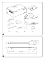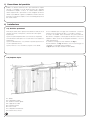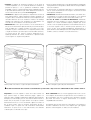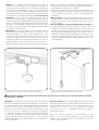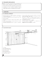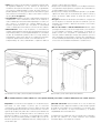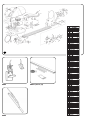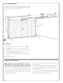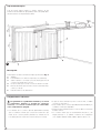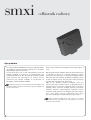
1
gearmotor for sectional doors
and overhead spring or
counterweight up-and-over doors
spido
instructions and warnings for the fitter
istruzioni e avvertenze per l’installatore
Instructions et recommandations pour l’installateur
Anweisungen und Hinweise für den Installateur
Instrucciones y advertencias para el instalador
Instrukcja instalowania
1
2
spido
Table of contents:
GB
page
page
1
Product description
2
4
Testing
4
2
2.1
2.2
2.3
2.4
2.5
2.6
Installation
Preliminary checks
Typical system layout
Limits of use
Installing SPIDO
Adjusting the drive bar
Fitting the limit switch slides
2
2
2
3
3
3
3
5
5.1
Maintenance
Disposal
4
4
6
Technical specifications
4
Instructions and warnings for
users of the SPIDO gear motor
5
3
Manual manoeuvre from the inside or release
4
Important information
Congratulations on choosing this Nice product. Please read this
handbook carefully.
To make these instructions easier to follow, we have, wherever possible,
put them in the order in which they will be carried out during the various
system installation phases.
Please read these instructions and the attached “Warnings for fitters” file
carefully before installing the product as they contain important
information concerning safety, installation, use and maintenance.
Anything not expressly specified in these instructions is forbidden.
Operations not indicated in these instructions may cause damage to the
product, people and property.
Nice declines all liability for badly built sectional doors or any
deformations that may occur during use.
Do not install the product in explosive atmospheres.
This product has been designed and produced for automating wellbalanced doors that can be opened by hand; it must therefore be
possible to completely open the door using a force of less than 150N
(15kg) and stop it in any position; after it has been released it must not
descend. It is forbidden to touch any mechanical parts (chain, trolley,
pinion) while SPIDO is working.
1
1) Product description
SPIDO is an electromechanical actuator for automating the
movement of sectional doors and overhead spring or counterweight
up-and-over doors. Thanks to its unique profile, installation is quick
and easy. The electrical control unit exploits the current sensitivity
system to measure the force developed by the motor and offers 5
levels of sensitivity. Manual opening and closing is simple and safe as
it releases the door from the drive trolley.
2) Installation
2.1) Preliminary checks
Before proceeding with the installation of any powered system, check
that the structure is suitable, that is, make sure it complies with
current standards and that:
the door does not stick when opening or closing;
the door does not require a force of over 150N (15kg) to be moved;
the door is well balanced, that is, if it stops in any position it remains
motionless;
the door moves silently, smoothly and doesn’t skid;
2.2) Typical system layout
1.
2.
3.
4.
5.
6.
7.
8.
3
2
SPIDO
24Vdc flashing lamp
Digital keypad switch
Pair of photocells
Internal push button strip
Schuko socket
24V light bulb max. 25W
“Step-by-step” button
the area identified for fitting the gear motor ensures the manual
manoeuvre can be made easily and safely;
please remember that SPIDO must power a door (sectional,
overhead spring or counterweight up-and-over) which must be in
good condition and safe; it cannot make up for defects caused by
incorrect installation or bad maintenance.
the packaging is undamaged, please see fig. 1;
referring to fig. 2, check that the fixing area is compatible with the
size of the gear motor.
Fig. 3 shows a typical installation of SPIDO.
2.3) Limits of use
GB
Sectional door (Max. H = 2400 mm) (fig. 4)
Counterweight up-and-over door (Max. H = 2400 mm) (fig. 4a)
Overhead spring up-and-over door (Max. H = 2600 mm) (fig. 4b)
4a
4
4b
2.4) Installing SPIDO
1. Connect the draw bar (27) to the curved bar (61) (Fig. 5);
2. Thread the cord (24) into the unthreaded hole of the release pin
and keep it flush at the other end;
3. Tie the two ends together after passing them through the hole in
the knob (25);
4. Insert the guide support bracket (32) into the chain tightening
device and fix it with the screw (48) and the nut (17) (Fig. 6);
5. Insert the slide (23) into the end of the profile (Fig. 7);
6. Insert the screws (35) into the two slots of the profile (Fig. 8);
7. Insert the profile by passing the chain over the motor pinion and
block it with the bracket (33) using two screws (44) (Fig. 9);
8. Tighten the chain slightly (Fig. 10);
9. Fix SPIDO to the frame of the door (recommended choice) or to
the wall with rivets or expansion grips keeping a distance of
between 30mm and 350mm from the maximum travel of the
door (Fig. 11);
10. Check the measurements for drilling the holes, insert and block
the support brackets (18) and fix SPIDO to the ceiling. Cut the
excess part of the bracket (Fig. 12).
2.5) Adjusting the drive bar
In order to ensure fine adjustment in the closing manoeuvre, loosen
the bolts of the drive bar with a 10mm wrench and adjust the travel
using the two slots or, if necessary, completely unscrewing the bolts
and changing the fixing position (Fig. 13).
! Thoroughly tighten all the screw connections.
2.6) Fitting the limit switch slides
! The limit switch slides may only be inserted when the
motor has stopped.
To fix the limit switch slides, follow the instructions referring to the
“electrical control unit”.
3
3) Manual manoeuvre from inside or release
! The manual manoeuvre must be made exclusively with
the door stopped and after disconnecting power from the
electrical control unit.
1. Pull the knob downwards and push the door (Fig. 14);
2. Turn the handle and push the door (Fig. 15).
4) Testing
The whole system must be tested by qualified and expert staff who
must perform the tests required, according to the level of risk.
To test SPIDO, proceed as follows:
• close the door;
• disconnect the power supply;
• release the gear motor;
• check that the slide way is clean and free from debris;
• completely open the door manually making sure to always exercise
a force of less than 150N (15kg);
• check that the door does not stick when moving;
• check that when the door is stopped at any point and released it
remains motionless;
•
•
•
•
check that the safety systems are in good condition;
check that the screw connections are perfectly tight;
check the chain is taut and that it slides well, lubricate if necessary;
after carrying out the above checks, block the gear motor and
power the control unit.
• adjust (from the electronic control unit) current sensitivity so that it
can move just the door;
• measure the force of impact as required by EN12445 and
EN12453 standards.
5) Maintenance
SPIDO does not require any special maintenance during its lifetime,
but a scheduled control at least every 6 months will not only ensure
that the gear motor lasts longer but also that the system works
correctly and safely.
Maintenance may only be performed by qualified staff.
Maintenance involves repeating the test procedure.
5.1) Disposal
SPIDO comprises various types of materials which must be disposed
of in compliance with the laws of the country of installation.
There are no particular dangers or risks deriving from demolition of the
system. If waste sorting is required, the components should be
grouped by type of material (electrical, aluminium, plastic, etc.).
6) Technical specifications
SP6000 230V ~
Power input
Line absorption
Max. absorbed power
Speed
Travel Y
Max. thrust
Max. traction
Operating temperature
Work cycles
Weight of motor (with profile)
Protection level
4
(Vac)
(A)
(W)
(m/s)
(mm)
(N)
(N)
(°C)
(%)
(kg)
(IP)
SP6000 110V ~
230
0,65
110
1,3
150
0,15
2500
650
700
-20 ÷ +50
30
12
40
GB
gearmotor for sectional doors
and overhead spring or
counterweight up-and-over doors
spido
Instructions and warnings for users of the
SPIDO gear motor
Congratulations on choosing a Nice product for your automation
system!
Nice S.p.A. produces components for automating gates, doors,
shutters and awnings: gear motors, control units, radio control units,
flashing lights, photocells and accessories.
Nice only uses first rate materials and production processes and
constantly develops innovative technical, aesthetic and ergonomic
solutions in order to make its products as simple to use as possible:
your fitter will certainly have chosen the most suitable article for your
requirements from the large range of Nice products.
Nice however, is not the producer of your automated system as this is
the result of a process of analysis, evaluation, choice of materials and
installation performed by your fitter.
Each automated system is unique and only your fitter has the experience
and professionalism required to create a system that is tailor-made to
your requirements, featuring long-term safety and reliability, and, above
all, professionally installed and compliant with current regulations.
An automated system is handy to have as well as being a valid security
system. Just a few, simple operations are required to ensure it lasts for
years.
Even if your automated system satisfies regulatory safety levels, this
does not eliminate “residue risks”, that is, the possibility of dangerous
situations being generated, usually due to irresponsible or incorrect use.
For this reason we would like to give you some suggestions on how to
avoid these risks:
• Before using your automated system for the first time, ask
your fitter to explain how residue risks can arise and spend a few
minutes reading the instructions and warnings for the user
handbook that the fitter will have given you. Keep this manual for
future use and, if you should ever sell your automated system, hand it
over to the new owner.
• Your automated system is a machine which carries out your
commands to the letter; irresponsible or incorrect use may cause
it to become dangerous: do not move the automated system if
animals or objects are in its working radius.
• Children: an automated system ensures a high level of safety as it
always offers reliable and safe operation and its detection systems
stop it from moving in the presence of people or objects. However,
children should not be allowed to play near it. Do not let them
accidentally use the system by leaving the remote control unit within
their reach: it is not a toy!
• Faults. If you notice any abnormal behaviour, disconnect the system
from the electricity supply immediately and perform the manual
release operation. Do not attempt to make repairs yourself but call in
your fitter: in the meantime the system can work as a non-automated
gate once the gear motor has been released as described further on.
• Maintenance. Just like all machines, your automated system
requires periodic maintenance to ensure it works as long as possible
and in total safety. Agree on a routine maintenance plan with your
fitter; Nice recommends a visit once every six months for normal
residential use but this period can vary depending on how often the
system is used.
All controls, maintenance work or repairs may only be carried out by
qualified personnel.
• Do not modify the system or its programming and adjustment
parameters even if you think you can do it: your fitter is responsible for
this.
• Final testing, routine maintenance and any repairs must be
documented by the fitter and such documents kept by the owner of
the system.
• Disposal. At the end of the life of the automatic system, make sure
that it is demolished by qualified personnel and that the materials are
recycled or disposed of according to local regulations.
• In case of breakage or during a power failure. While waiting for your
fitter to call (or power to come on again if the system does not have
buffer batteries), the system can be used just like any other manual
opening system. To do this, perform the manual release operation:
this can be done by the user and Nice has made it as easy as
possible, without the need for tools or physical effort.
Pull the knob downwards and push the door.
Turn the handle and push the door.
! The manual manoeuvre must be made exclusively with the door stopped and after disconnecting power from the electrical
control unit.
Important: if the radio control unit (if supplied) starts working badly
after a time, or does not work at all, the batteries may be flat (They can
last from several months to two/three years depending on the type). You
can notice this from the fact that the transmission OK LED is faint,
doesn’t light up at all, or lights up for just a moment. Before contacting
your fitter, try exchanging the battery with that of another transmitter you
know that works: if this is the reason for the fault, just replace the battery
with another one of the same kind.
Are you satisfied? If you wish to add a new automated system to
your house, contact your fitter and we at Nice will provide the advice of
a specialist, the most developed products on the market, leading-edge
operativeness and maximum compatibility.
Thank you for reading these suggestions and we trust you are fully
satisfied with your new system: please contact your fitter for all your
current or future requirements.
spido
Indice:
I
pag.
pag.
1
Descrizione del prodotto
8
4
Collaudo
10
2
2.1
2.2
2.3
2.4
2.5
2.6
Installazione
Verifiche preliminari
Impianto tipico
Limiti d’impiego
Installazione SPIDO
Impostazione asta di trasmissione
Inserimento slitte di finecorsa
8
8
8
9
9
9
9
5
5.1
Manutenzione
Smaltimento
10
10
6
Caratteristiche tecniche
10
3
Manovra manuale dall’interno o sblocco
Istruzioni ed avvertenze destinate
all’utilizzatore del motoriduttore SPIDO 11
10
Avvertenze importanti
Nice si congratula per la scelta di questo prodotto e vi invita a leggere con
molta attenzione queste pagine.
Per rendere più semplice l’uso di queste istruzioni si è cercato, per
quanto possibile, di impaginarle rispettando l’ordine con cui devono
essere eseguite le varie fasi dell’installazione dell’impianto.
È necessario leggere attentamente le istruzioni e il fascicolo allegato
“Avvertenze per l’installatore” prima di procedere all’installazione, in
quanto forniscono importanti indicazioni riguardanti la sicurezza,
l’installazione, l’uso e la manutenzione.
Tutto quello che non è espressamente previsto in queste istruzioni non è
permesso. Infatti usi non indicati nelle istruzioni potrebbero essere fonte di
danni al prodotto e mettere in pericolo persone e cose.
Nice declina qualsiasi responsabilità dall’inosservanza della buona
tecnica nella costruzione delle porte sezionali, nonché dalle deformazioni
che potrebbero verificarsi durante l’uso.
Non installare il prodotto in atmosfera esplosiva.
Questo prodotto è stato progettato e realizzato per automatizzare porte
apribili manualmente e ben bilanciate, perciò, la porta deve potersi aprire
per tutta la corsa con una forza inferiore a 150N (15kg) e fermato in
qualsiasi posizione, azionato lo sblocco, non deve accennare a scendere.
E’ vietato toccare qualsiasi organo meccanico (catena, carrello, pignone)
durante il funzionamento.
7
1) Descrizione del prodotto
SPIDO è un attuatore elettromeccanico per l’automazione di porte
sezionali, a contrappesi e a molle. Grazie al profilo unico permette
un’installazione semplice e veloce. La centrale elettrica utilizza il
sistema amperometrico per rilevare la forza sviluppata dal motore
offrendo la possibilità di scegliere la sensibilità tra 5 livelli. La manovra
manuale è un’operazione semplice e sicura che disimpegna il portone
dal carrello di traino.
2) Installazione
2.1) Verifiche preliminari
Prima di procedere ad una qualsiasi motorizzazione verificare che la
struttura sia idonea, in altre parole, conforme alle norme vigenti.
In particolare:
la porta non presenti punti d’attrito sia in chiusura sia in apertura;
la movimentazione della porta non necessiti di una forza superiore a
150N (15kg);
la porta sia ben bilanciata, ossia, fermata in qualsiasi posizione non
accenni a riprendere il moto;
la porta, nella sua corsa, sia silenziosa, regolare e non sbandi;
2.2) Impianto tipico
1.
2.
3.
4.
5.
6.
7.
8.
3
8
SPIDO
Lampeggiante 24Vdc
Selettore a tastiera digitale
Coppia di fotocellula
Pulsantiera interna
Presa schuko
Lampadina 24V 25W max
Pulsante “Passo-Passo”
la zona individuata per il fissaggio del motoriduttore consenta di
operare la manovra manuale di sblocco con facilità e sicurezza;
si ricorda che SPIDO deve motorizzare una porta (sezionale,
basculante a contrappesi o a molle) di per sé efficiente e sicura e non
sopperire a difetti causati da una sbagliata installazione, o da una
cattiva manutenzione;
la confezione sia integra, facendo riferimento alla fig. 1;
facendo riferimento alla fig. 2 verificare che la zona di fissaggio sia
compatibile con l’ingombro del motoriduttore.
La fig. 3 riporta una tipica installazione dello SPIDO.
2.3) Limiti d’impiego
Porta sezionale (H max = 2400 mm) (fig. 4)
Porta basculante a contrappesi (H max = 2400 mm) (fig. 4a)
Porta basculante a molle (H max = 2600 mm) (fig. 4b)
I
4a
4
4b
2.4) Installazione SPIDO
1. Assemblare l’asta di traino (27) con l’asta curva (61) (Fig. 5);
2. Far passare la corda (24) nel foro non filettato del perno di
sblocco e pareggiarla all’altra estremità;
3. Annodare i due capi assieme dopo averli fatti passare nel foro del
pomello (25);
4. Inserire la staffa supporto guida (32) nel rinvio tendicatena e
fissarla con la vite (48) e con dado (17) (Fig. 6);
5. Infilare la slitta (23) nell’estremità del profilo (Fig. 7);
6. Infilare le viti (35) nelle due feritoie del profilo (Fig. 8);
7. Inserire il profilo facendo passare la catena oltre il pignone del
motore e bloccarlo con la staffa (33) tramite due viti (44) (Fig. 9);
8. Mettere in leggera tensione la catena (Fig. 10);
9. Fissare SPIDO al telaio della porta (scelta consigliata) oppure al
muro con rivetti o tasselli tenendo una distanza compresa tra
30mm e 350mm dalla corsa massima della porta stessa
(Fig. 11);
10. Verificare le misure per la foratura, inserire e bloccare le staffe di
sostegno (18) e fissare SPIDO al soffitto. Tagliare la parte
eccedente delle staffe (Fig. 12).
2.5) Impostazione asta di trasmissione
Per avere una regolazione millimetrica nella manovra di chiusura agire
sull’asta di trasmissione con una chiave da 10mm, allentando i
bulloni e regolando la corsa tramite le due asole o se necessario
svitando completamente i bulloni e cambiando la posizione di
fissaggio (Fig. 13).
! Serrare a fondo tutti i collegamenti a vite.
2.6) Inserimento slitte di finecorsa
! L’inserimento delle slitte di finecorsa deve avvenire
esclusivamente a motore fermo.
Per il fissaggio delle slitte di finecorsa seguire quanto descritto nelle
istruzioni della “centrale elettrica”.
9
3) Manovra manuale dall’interno o sblocco
! La manovra manuale deve avvenire esclusivamente a
porta ferma e dopo aver tolto l’alimentazione alla centrale
elettrica.
1. Tirare il pomello verso il basso e agire sulla porta manualmente
(Fig. 14);
2. Ruotare la maniglia e agire sulla porta manualmente (Fig. 15).
4) Collaudo
Il collaudo dell’intero impianto deve essere eseguito da personale
esperto e qualificato che deve farsi carico delle prove richieste, in
funzione del rischio presente. Per il collaudo di SPIDO si dovrà
seguire questa procedura:
• chiudere la porta;
• togliere alimentazione;
• sbloccare il motoriduttore;
• verificare che la corsia di scorrimento sia pulita e libera da detriti;
• aprire manualmente il portone per tutta la sua corsa assicurandosi
di esercitare uno sforzo sempre inferiore a 150N (15kg);
• verificare che la porta durante il moto non subisca punti d’attrito;
• verificare che la porta fermata in qualsiasi punto e sbloccata, non
accenni a cadere;
• verificare che i sistemi di sicurezza siano in buono stato;
• verificare che i collegamenti a vite siano ben stretti;
• verificare la tensione della catena e il suo buon scorrimento e se
necessario lubrificarla;
• terminate le verifiche ribloccare il motoriduttore e rialimentare la
centrale;
• regolare (dalla centrale elettronica) la sensibilità amperometrica in
modo che riesca a muovere solo ed unicamente la porta;
• misurare la forza d’impatto come previsto dalla normativa
EN12445 e EN12453.
5) Manutenzione
SPIDO non necessità di interventi particolari durante la sua vita
tuttavia, una manutenzione periodica, almeno ogni 6 mesi, non solo
garantisce una maggiore vita, ma anche un corretto e sicuro
funzionamento del sistema.
Solo personale qualificato può eseguire la manutenzione.
La manutenzione consiste nel ripetere la procedura di
collaudo.
5.1) Smaltimento
SPIDO è costituito da varie tipologie di materiali e l’eliminazione di
questi va effettuata rispettando le norme vigenti nei singoli Paesi.
Nel caso di demolizione dell‘automatismo non esistono particolari
pericoli o rischi derivati dall’automazione stessa. E’ opportuno, in caso
si desideri effettuare una raccolta differenziata, che i materiali vengano
separati per tipologia (parti elettriche, alluminio, plastica, ecc.).
6) Caratteristiche tecniche
SP6000 230V ~
Alimentazione
Assorbimento linea
Massima potenza assorbita
Velocità
Corsa Y
Spinta max.
Trazione max.
Temperatura di esercizio
Cicli di lavoro
Peso motore (con profilo)
Grado di protezione
10
(Vac)
(A)
(W)
(m/s)
(mm)
(N)
(N)
(°C)
(%)
(kg)
(IP)
SP6000 110V ~
230
0,65
110
1,3
150
0,15
2500
650
700
-20 ÷ +50
30
12
40
motoriduttore
per porte sezionali
o basculanti a molle
o a contrappesi
I
spido
Istruzioni ed avvertenze destinate
all’utilizzatore del motoriduttore SPIDO
Complimenti per aver scelto per la vostra automazione un prodotto Nice!
Nice S.p.A. produce componenti per l’automazione di cancelli, porte,
tapparelle e tende da sole: motoriduttori, centrali di comando,
radiocomandi, lampeggianti, fotocellule e accessori.
Nice utilizza solo materiali e lavorazioni di qualità, e per vocazione ricerca
soluzioni innovative che semplifichino al massimo l’utilizzo delle sue
apparecchiature, curate nelle soluzioni tecniche, estetiche, ergonomiche:
nella grande gamma Nice il vostro installatore avrà senz’altro scelto il
prodotto più adatto alle vostre esigenze.
Nice non è però il produttore della vostra automazione, che è invece il
risultato di un’opera di analisi, valutazione, scelta dei materiali, e
realizzazione dell’impianto eseguita dal vostro installatore di fiducia.
Ogni automazione è unica e solo il vostro installatore possiede l’esperienza
e la professionalità necessarie ad eseguire un impianto secondo le vostre
esigenze, sicuro ed affidabile nel tempo, e soprattutto a regola d’arte,
rispondente cioè alle normative in vigore.
Un impianto di automazione è una bella comodità, oltre che un valido
sistema di sicurezza e, con poche, semplici attenzioni, è destinato a durare
negli anni.
Anche se l’automazione in vostro possesso soddisfa il livello di sicurezza
richiesto dalle normative, questo non esclude l’esistenza di un “rischio
residuo”, cioè la possibilità che si possano generare situazioni di pericolo,
solitamente dovute ad un utilizzo incosciente o addirittura errato, per
questo motivo desideriamo darvi alcuni consigli sui comportamenti da
seguire per evitare ogni inconveniente:
• Prima di usare per la prima volta l’automazione, fatevi spiegare
dall’installatore l’origine dei rischi residui, e dedicate qualche minuto alla
lettura del manuale di istruzioni ed avvertenze per l’utilizzatore
consegnatovi dall’installatore. Conservate il manuale per ogni dubbio
futuro e consegnatelo ad un eventuale nuovo proprietario
dell’automazione.
• La vostra automazione è un macchinario che esegue
fedelmente i vostri comandi; un uso incosciente ed improprio può
farlo diventare pericoloso: non comandate il movimento
dell’automazione se nel suo raggio di azione si trovano persone, animali
o cose.
• Bambini: un impianto di automazione garantisce un alto grado di
sicurezza, impedendo con i suoi sistemi di rilevazione il movimento in
presenza di persone o cose, e garantendo un’attivazione sempre
prevedibile e sicura. È comunque prudente vietare ai bambini di giocare
in prossimità dell’automazione e per evitare attivazioni involontarie non
lasciare i telecomandi alla loro portata: non è un gioco!
• Anomalie. Non appena notate qualunque comportamento anomalo da
parte dell’automazione, togliete alimentazione elettrica all’impianto ed
eseguite lo sblocco manuale. Non tentate da soli alcuna riparazione, ma
richiedete l’intervento del vostro installatore di fiducia: nel frattempo
l’impianto può funzionare come un’apertura non automatizzata, una
volta sbloccato il motoriduttore come descritto più avanti.
• Manutenzione. Come ogni macchinario la vostra automazione ha
bisogno di una manutenzione periodica affinché possa funzionare più a
lungo possibile ed in completa sicurezza. Concordate con il vostro
installatore un piano di manutenzione con frequenza periodica; Nice
consiglia un intervento ogni 6 mesi per un normale utilizzo domestico,
ma questo periodo può variare in funzione dell’intensità d’uso.
Qualunque intervento di controllo, manutenzione o riparazione deve
essere eseguito solo da personale qualificato.
• Anche se ritenete di saperlo fare, non modificate l’impianto ed i parametri
di programmazione e di regolazione dell’automazione: la responsabilità è
del vostro installatore.
• Il collaudo finale, le manutenzioni periodiche e le eventuali riparazioni
devono essere documentate da chi le esegue e i documenti conservati
dal proprietario dell’impianto.
• Smaltimento. Al termine della vita dell’automazione, assicuratevi che lo
smantellamento sia eseguito da personale qualificato e che i materiali
vengano riciclati o smaltiti secondo le norme valide a livello locale.
• In caso di rotture o assenza di alimentazione. Attendendo
l’intervento del vostro installatore, (o il ritorno dell’energia elettrica se
l’impianto non è dotato di batterie tampone), l’impianto può essere
azionato come una qualunque apertura non automatizzata. Per fare ciò
è necessario eseguire lo sblocco manuale: questa operazione, che è
l’unica che può essere eseguita dall’utilizzatore dell’automazione, è
particolarmente curata da Nice per assicurarvi sempre la massima facilità
di utilizzo, senza uso di attrezzi o necessità di sforzo fisico.
Tirare il pomello verso il basso e agire sulla porta manualmente.
Ruotare la maniglia e agire sulla porta manualmente.
! La manovra manuale deve avvenire esclusivamente a porta ferma e dopo aver tolto l’alimentazione alla centrale elettrica.
Importante: se il vostro impianto è dotato di un radiocomando che
dopo qualche tempo vi sembra funzionare peggio, oppure non
funzionare affatto, potrebbe semplicemente dipendere dall’esaurimento
della pila (a seconda del tipo, possono trascorrere da diversi mesi fino a
due/tre anni). Ve ne potete accorgere dal fatto che la spia di conferma
della trasmissione è fioca, non si accende affatto, oppure si accende solo
per un breve istante. Prima di rivolgervi all’installatore provate a
scambiare la pila con quella di un altro trasmettitore eventualmente
funzionante: se questa fosse la causa dell’anomalia, sarà sufficiente
sostituire la pila con altra dello stesso tipo.
Siete soddisfatti? Nel caso voleste aggiungere nella vostra casa un
nuovo impianto di automazione, rivolgendovi allo stesso installatore e a
Nice vi garantirete, oltre che la consulenza di uno specialista e i prodotti
più evoluti del mercato, il migliore funzionamento e la massima
compatibilità delle automazioni.
Vi ringraziamo per aver letto queste raccomandazioni, e vi auguriamo la
massima soddisfazione dal vostro nuovo impianto: per ogni esigenza
presente o futura rivolgetevi con fiducia al vostro installatore.
spido
Table des matières :
page
page
1
Description du produit
14
4
Essai de fonctionnement
16
2
2.1
2.2
2.3
2.4
2.5
2.6
Installation
Contrôles préliminaires
Installation typique
Limites d’application
Installation SPIDO
Réglage barre de transmission
Montage dispositifs de fin de course
14
14
14
15
15
15
15
5
5.1
Maintenance
Mise au rebut
16
16
6
Caractéristiques techniques
16
3
Manœuvre manuelle de l’intérieur ou débrayage
16
Instructions et recommandations destinées
à l’utilisateur de l’opérateur SPIDO
16
Recommandations importantes
Nice vous félicite pour avoir choisi ce produit et vous invite à lire très
attentivement ces pages.
Pour faciliter la compréhension de ces instructions, nous avons tenté,
dans la mesure du possible, de les présenter en respectant l’ordre dans
lequel vous devez exécuter les différentes phases d’installation de
l’automatisme.
Il faut lire attentivement les instructions et le fascicule joint
“Recommandations pour l’installateur” avant de procéder à l’installation
car ils fournissent des indications importantes concernant la sécurité,
l’installation, l’utilisation et la maintenance de l’automatisme.
Tout ce qui n’est pas expressément prévu dans ces instructions n’est
pas autorisé. En effet les utilisations non décrites dans les instructions
pourraient être une source de dommages pour le produit et mettre en
danger les personnes et les choses.
Nice décline toute responsabilité en cas de non-observation des règles
de l’art dans la construction des portes sectionnelles ainsi que des
déformations qui pourraient se vérifier durant l’utilisation.
Ne pas installer le produit en présence d’atmosphère explosive.
Ce produit a été projeté et réalisé pour automatiser des portes ouvrables
manuellement et bien équilibrées, c’est-à-dire que la porte doit pouvoir
s’ouvrir jusqu’en fin de course avec une force inférieure à 150 N (15 kg)
et que lorsqu’elle est arrêtée dans n’importe quelle position, après avoir
actionné le débrayage, elle ne doit pas amorcer la descente.
Il est interdit de toucher les organes mécaniques (chaîne, chariot,
pignon) pendant le fonctionnement.
13
F
1) Description du produit
SPIDO est un opérateur électromécanique pour l’automatisation de
portes sectionnelles et de portes basculantes à contrepoids ou à
ressorts. Grâce au rail unique, il permet une installation simple et
rapide. La logique de commande est dotée d’un système
ampèremétrique pour détecter la force développée par le moteur en
offrant la possibilité de choix entre 5 niveaux de sensibilité. La
manœuvre manuelle est une opération simple et sûre qui libère la
porte du chariot de traction.
2) Installation
2.1) Contrôles préliminaires
Avant de procéder à l’installation, il faut vérifier que la structure est
adaptée, en d’autres termes, qu’elle est conforme aux normes en
vigueur et en particulier, il faut vérifier que:
la porte ne présente pas de points de frottement aussi bien en
fermeture qu’en ouverture;
l’ouverture ou la fermeture de la porte ne nécessite pas une force
supérieure à 150 N (15 kg);
la porte est bien équilibrée, à savoir, que lorsque qu’elle est arrêtée
dans une position quelconque, elle n’amorce aucun mouvement;
la porte, dans sa course, est silencieuse, régulière et sans
embardées;
2.2) Installation typique
1.
2.
3.
4.
5.
6.
7.
8.
3
14
SPIDO
Clignotant 24 Vcc
Clavier à code
Paire de photocellules
Commande interne
Prise schuko
Lampe 24 V 25 W max.
Touche Pas-à-pas
la zone choisie pour la fixation de l’opérateur permet d’actionner
manuellement le débrayage de manière facile et sûre;
nous rappelons que SPIDO est conçu pour la motorisation d’une
porte (sectionnelle, basculante à contrepoids ou à ressorts) et est en
soi efficace et sûr; il ne peut toutefois suppléer aux défauts causés
par une installation erronée ou par une mauvaise maintenance.
l’emballage contient tous les éléments, comme l’illustre la fig. 1;
en se référant à la fig. 2, vérifier que la zone de fixation est
compatible avec l’encombrement de l’opérateur.
La fig. 3 illustre une installation typique du SPIDO.
2.3) Limites d’application
Porte sectionnelle (H max. = 2400 mm) (fig. 4)
Porte basculante à contrepoids (H max. = 2400) (fig. 4a)
Porte basculante à ressorts (H max. = 2600 mm) (fig. 4b)
F
4a
4
4b
2.4) Installation SPIDO
1. Assembler la barre de traction (27) avec la barre courbe (61) (fig. 5);
2. Faire passer la corde (24) dans le trou non fileté de l’axe du
débrayage et la reporter à l’autre extrémité, bout à bout;
3. Nouer ensemble les deux extrémités après les avoir fait passer
dans le trou de la poignée (25);
4. Insérer l’étrier de support du rail (32) dans le renvoi de tension
chaîne et le fixer avec la vis (48) et avec l’écrou (17) (fig. 6);
5. Enfiler le chariot (23) à l’extrémité du rail (fig. 7);
6. Introduire les vis dans les deux fentes du rail (fig. 8);
7. Insérer le rail en faisant passer la chaîne au-delà du pignon du moteur
et le bloquer avec la patte (33) au moyen de deux vis (44) (fig. 9);
8. Tendre légèrement la chaîne (fig. 10);
9. Fixer SPIDO au bâti de la porte (choix conseillé) ou au mur avec
des rivets ou des vis tamponnées en maintenant une distance
comprise entre 30 mm et 350 mm par rapport à la course
maximum de la porte (fig. 11);
10. Vérifier les mesures pour le perçage, insérer et bloquer les pattes
de support (18) et fixer SPIDO au plafond. Couper la partie des
pattes de support qui dépasse (fig. 12).
2.5) Réglage barre de transmission
Pour obtenir un réglage millimétrique dans la manœuvre de
fermeture, agir sur la barre de transmission avec une clé de 10 mm
en desserrant les boulons et en réglant la course à l’aide des deux
fentes ou, si nécessaire, en dévissant complètement les boulons et
en changeant la position de fixation (fig. 13).
! Serrer à fond toutes les vis d’assemblage.
2.6) Montage dispositifs de fin de course
! Le montage des dispositifs de fin de course doit être
fait exclusivement quand le moteur est arrêté.
Pour la fixation des dispositifs de fin de course, suivre les opérations
décrites dans les instructions de l’armoire de commande.
15
3) Manœuvre manuelle de l’intérieur ou débrayage
!
La manœuvre manuelle doit être faite exclusivement
avec la porte arrêtée et après avoir coupé l’alimentation
électrique de l’armoire de commande.
1. Tirer la poignée vers le bas et agir manuellement sur la porte
(fig. 14);
2. Tourner la poignée et agir manuellement sur la porte (fig. 15).
4) Essai de fonctionnement
L’essai de fonctionnement de toute l’installation doit être effectué par
du personnel expert et qualifié qui doit se charger des essais requis
en tenant compte du risque présent.
Pour l’essai de SPIDO, suivre cette procédure :
• fermer la porte;
• couper l’alimentation de l’armoire de commande;
• débrayer l‘opérateur;
• vérifier que le rail de coulissement est propre et sans détritus;
• ouvrir manuellement la porte jusqu’en fin de course en veillant à ne
pas exercer une force supérieure à 150 N (15 kg);
• vérifier l’absence de points de frottement durant le mouvement de
la porte;
• vérifier que la porte, si elle est arrêtée en un point quelconque et
débrayée, n’amorce pas la descente;
• vérifier que les systèmes de sécurité sont en bon état;
• vérifier que les vis d’assemblage sont serrées à fond;
• vérifier la tension de la chaîne et qu’elle coulisse bien, si
nécessaire la graisser ;
• après avoir terminé les vérifications, réembrayer l’opérateur et
rétablir l’alimentation de l’armoire de commande.
• régler (à partir de l’armoire de commande) la sensibilité
ampèremétrique de manière à ce qu’elle n’arrive à bouger que la
porte;
• mesurer la force d’impact conformément aux normes EN12453 et
EN12445.
5) Maintenance
SPIDO ne requiert pas de maintenance particulière mais un contrôle
programmé au moins tous les six mois permet d’assurer à
l’opérateur une plus longue vie et un fonctionnement correct et sûr
du système.
La maintenance doit être effectuée exclusivement par du personnel
qualifié.
La maintenance consiste simplement à répéter toute la
procédure de l’essai de fonctionnement.
5.1) Mise au rebut
SPIDO est constitué de différents types de matériaux et leur mise au
rebut doit être effectuée en respectant les normes en vigueur dans le
pays d’installation.
En cas de démantèlement de l’automatisme, il n’existe pas de
dangers ou risques dérivant de l’automatisme proprement dit.
Dans le cas de récolte différenciée, il est opportun d’effectuer un tri
sélectif suivant le type de matériau (partes électriques, aluminium,
plastique, etc.)
6) Caractéristiques techniques
SP6000 230V ~
Alimentation
Courant absorbé
Puissance max. absorbée
Vitesse
Course Y
Poussée max.
Traction max.
Température de fonctionnement
Cycles de travail
Poids moteur (avec rail)
Indice de protection
16
(Vac)
(W)
(A)
(m/s)
(N)
(mm)
(N)
(°C)
(%)
(kg)
(IP)
SP6000 110V ~
230
0,65
110
1,3
150
0,15
2500
650
700
-20 ÷ +50
30
12
40
opérateur pour portes
sectionnelles et basculantes
à ressorts ou contrepoids
F
spido
Instructions et avertissements destinés à
l’utilisateur de l’opérateur SPIDO
Félicitations pour avoir choisi un produit Nice pour votre installation
d’automatisation!
Nice S.p.A. produit des composants pour l’automatisme de portails,
portes, volets roulants et stores : opérateurs, armoires de commande,
radiocommandes, clignotants, photocellules et accessoires.
Nice utilise exclusivement des matériaux et des usinages de qualité et
par vocation, elle recherche des solutions innovantes qui simplifient au
maximum l’utilisation de ses appareils, très soignés sur le plan des
solutions techniques, esthétiques et ergonomiques: dans la vaste
gamme Nice, votre installateur aura choisi sans aucun doute le produit
le plus adapté à vos exigences.
Nice n’est toutefois pas le producteur de votre automatisme qui est en
effet le résultat d’un travail d’analyse, évaluation, choix des matériaux et
réalisation de l’installation, exécuté par votre installateur de confiance.
Chaque automatisme est unique et seul votre installateur possède
l’expérience et la compétence professionnelle nécessaires pour réaliser
une installation répondant à vos exigences, sûre et fiable dans le temps
et surtout, exécutée dans les règles de l’art et conforme par conséquent
aux normes en vigueur.
Une installation d’automatisation est une belle commodité ainsi qu’un
système de sécurité valable ; avec quelques attentions très simples, elle
est destinée à durer dans le temps.
Même si l’automatisme en votre possession satisfait le niveau de
sécurité requis par les normes, cela n’exclut pas la persistance d’un
“risque résiduel”, c’est-à-dire la possibilité de situations de danger dues
généralement à une utilisation inconsciente, voire erronée. C’est la
raison pour laquelle nous désirons vous donner quelques conseils sur
les comportements à adopter pour éviter tout inconvénient :
• Avant d’utiliser pour la première fois l’automatisme, faitesvous expliquer par l’installateur l’origine des risques résiduels et
consacrez quelques minutes à la lecture du manuel d’instructions
et d’avertissement pour l’utilisateur qui vous est remis par
l’installateur. Conservez le manuel pour pouvoir le consulter pour
n’importe quel doute futur et remettez-le à l’éventuel nouveau
propriétaire de l’automatisme.
• Votre automatisme est un équipement qui exécute
fidèlement vos commandes; une utilisation inconsciente et
incorrecte peut le rendre dangereux: ne commandez pas le
mouvement de l’automatisme si des personnes, des animaux ou des
objets se trouvent dans son rayon d’action.
• Enfants: une installation d’automatisation garantit un degré de
sécurité élevé en empêchant avec ses systèmes de détection le
mouvement en présence de personnes ou d’objets et en garantissant
une activation toujours prévisible et sûre. Il est prudent toutefois
d’éviter de laisser jouer les enfants à proximité de l’automatisme et
pour éviter les activations involontaires, de ne pas laisser à leur portée
les émetteurs qui commandent la manœuvre: ce n’est pas un jeu!
• Anomalies: si vous notez une anomalie quelconque dans le
fonctionnement de l’automatisme, coupez l’alimentation électrique de
l’installation et procédez au débrayage manuel. Ne tentez jamais de le
réparer vous-même mais demandez l’intervention de votre installateur
de confiance : dans l’intervalle, l’installation peut fonctionner comme
un système non automatisé, après avoir débrayé l’opérateur suivant
les indications données plus loin.
• Maintenance: comme tout appareil, votre automatisme a besoin
d’une maintenance périodique pour pouvoir fonctionner le plus
longtemps possible et en toute sécurité. Établissez avec votre
installateur un plan de maintenance périodique programmée ; Nice
conseille une intervention tous les 6 mois pour une utilisation
domestique normale mais celle période peut varier en fonction de
l’intensité d’utilisation. Toute intervention de contrôle, maintenance ou
réparation doit être exécutée exclusivement par du personnel qualifié.
• Même si vous estimez en être capable, ne modifiez pas l’installation et
les paramètres de programmation et de réglage de l’automatisme : la
responsabilité en incombe à votre installateur.
• L’essai de fonctionnement final, les maintenances périodiques et les
éventuelles réparations doivent être documentés par qui les exécute
et les documents doivent être conservés par le propriétaire de
l’installation.
• Mise au rebut. À la fin de la vie de l’automatisme, assurez-vous que
le démantèlement est effectué par du personnel qualifié et que les
matériaux sont recyclés ou mis au rebut en respectant les normes
locales en vigueur.
• En cas de ruptures ou absence d’alimentation électrique. En
attendant l’intervention de votre installateur (ou le retour du courant si
l’installation est dépourvue de batterie tampon), l’installation peut être
actionnée comme n’importe quel autre système non automatisé. Pour
cela, il faut effectuer le débrayage manuel : cette opération, qui est la
seule pouvant être effectuée par l’utilisateur de l'automatisme, a fait
l’objet d’une étude particulière de la part de Nice pour vous assurer
toujours une utilisation extrêmement simple et aisée, sans aucun outil
ou effort physique.
Tirer la poignée vers le bas et agir manuellement sur la porte.
Tourner la poignée et agir manuellement sur la porte.
! La manœuvre manuelle doit être faite exclusivement avec la porte arrêtée et après avoir coupé l’alimentation électrique
de l’armoire de commande.
Important: si votre installation est munie d’une radiocommande qui au
bout d’une certaine période présente des problèmes de fonctionnement
ou ne fonctionne plus du tout, cela pourrait dépendre tout simplement
du fait que la pile est usagée (suivant le type de pile, il peut s’écouler
plusieurs mois jusqu’à deux ou trois ans). Vous pouvez vérifier cet état
de chose si le voyant de confirmation de la transmission est faible, s’il
ne s’allume plus du tout ou s’il ne s’allume qu’un bref instant. Avant de
vous adresser à l’installateur, essayez de remplacer la pile en utilisant
celle d’un autre émetteur qui fonctionne encore : si cette intervention
remédie au problème, il vous suffit de remplacer la pile usagée par une
neuve du même type.
Vous êtes satisfait? Si vous désirez équiper votre maison d’un nouvel
automatisme, adressez-vous au même installateur et à Nice. Vous serez
sûr de bénéficier ainsi, en plus du conseil d’un spécialiste et des
produits les plus évolués du marché, également du meilleur
fonctionnement et de la compatibilité parfaite des différents
automatismes installés.
Nous vous remercions d’avoir lu ces recommandations et nous
espérons que votre nouvelle installation vous donnera entière
satisfaction : pour tout besoin présent ou futur, adressez-vous en toute
confiance à votre installateur.
spido
Inhaltsverzeichnis
S.
S.
1
Beschreibung des Produktes
20
4
Prüfung
22
2
2.1
2.2
2.3
2.4
2.5
2.6
Installation
Vorprüfungen
Typische Anlage
Einsatzgrenzen
Installation von SPIDO
Einstellung der Antriebsstange
Einbau der Endschalterschlitten
20
20
20
21
21
21
21
5
5.1
Wartung
Entsorgung
22
22
6
Technische Merkmale
22
3
Manuelle Betätigung von innen oder Entriegelung 22
Anweisungen und Hinweise für den
Benutzer des toröffners SPIDO
D
23
Wichtige Hinweise
Nice gratuliert Ihnen zur Wahl dieses Produktes und bittet Sie, diese
Seiten sehr aufmerksam zu lesen.
Um den Gebrauch dieser Anweisungen so einfach wie möglich zu
machen, wurde soweit möglich versucht, die Seiten in der Reihe
einzuordnen, in der die verschiedenen Installationsschritte der Anlage
auszuführen sind.
Vor der Installation sind die Anweisungen und das anliegende Heft
„Hinweise für den Installateur“ aufmerksam zu lesen, da sie, was
Sicherheit, Installation, Bedienung und Wartung betrifft, wichtige
Hinweise liefern.
Alles nicht ausdrücklich in diesen Anweisungen vorgesehene ist
unzulässig; nicht in den Anweisungen vorgesehene Verwendungen
könnten das Produkt beschädigen und Personen und Gegenstände
gefährden.
Nice übernimmt keine Haftung weder für die gute Konstruktionstechnik
der Sektionaltore noch für eventuelle Verformungen während des
Betriebs.
Das Produkt nicht in Ex-gefährdeter Umgebung installieren.
Das vorliegende Produkt wurde für die Automatisierung von Toren
entwickelt und hergestellt, die von Hand geöffnet werden können und ein
gutes Gleichgewicht haben, es muss daher möglich sein, das Tor auf
seinem ganzen Lauf mit einer Kraft unter 150N (15 kg) zu öffnen, und
wenn das Tor in beliebiger Stellung angehalten wird, darf es nach
Betätigung der Entriegelung nicht heruntergehen.
Während des Betriebs ist es verboten, Bewegungsteile (Kette, Wagen,
Ritzel) zu berühren.
19
1) Beschreibung des Produktes
SPIDO ist ein elektromechanischer Toröffner für die Automatisierung
von Sektionaltoren und von Schwingtoren mit Gegengewichten und
Federn. Dank nur einem Profil kann SPIDO auf einfache und schnelle
Weise installiert werden. Die Steuerung wendet eine Stromregelung
für die Messung der vom Motor entwickelten Kraft an und bietet die
Möglichkeit, zwischen 5 Empfindlichkeitsstufen zu wählen. Die
manuelle Betätigung ist ein einfacher und sicherer Vorgang, bei dem
das Tor nicht mehr an den Zugwagen gebunden ist.
2) Installation
2.1) Vorprüfungen
Vor dem Einbau einer Automatisierung muss geprüft werden, ob die
Struktur dafür geeignet ist bzw. ob sie den gültigen Vorschriften
entspricht.
Insbesondere:
darf das Tor weder in Öffnung noch in Schließung Reibungsstellen
aufweisen;
dürfen für die Bewegung des Tors eine Kraft nicht über 150N (15kg)
erforderlich sein;
muss das Tor ein gutes Gleichgewicht besitzen bzw. darf es sich
nicht bewegen, wenn es angehalten wird;
muss das Tor einen leisen und regelmäßigen Lauf haben und darf
nicht entgleisen;
2.2) Typische Anlage
1.
2.
3.
4.
5.
6.
7.
8.
3
20
SPIDO
Blinkleuchte 24 Vdc
Drahtloses digitales Codeschloss
Photozellenpaar
Interne Druckknopftafel
Schukosteckdose
Beleuchtung 24V max. 25W
Taste „Schrittbetrieb“
muss der zur Befestigung des Toröffners gewählte Bereich so sein,
dass die manuelle Entriegelung auf leichte und einfache Weise
betätigt werden kann;
dient SPIDO für die Automatisierung von einem an und für sich
effizienten
und sicheren Tor (Sektionaltor, Schwingtor mit
Gegengewichten oder Federn) und nicht dazu, Installationsfehlern
oder einer schlechten Wartung Abhilfe zu schaffen;
muss die Verpackung unbeschädigt sein, siehe dazu Abb. 1;
ist unter Bezugnahme auf Abb. 2 zu prüfen, ob der
Befestigungsbereich für die Gesamtabmessungen des Toröffners
geeignet ist.
In Abb. 3 ist eine typische Installation von SPIDO gezeigt.
2.3) Einsatzgrenzen
Sektionaltor (max. H = 2400 mm) (Abb. 4)
Schwingtor mit Gegengewichten (max. H = 2400 mm) (Abb. 4a)
Schwingtor mit Federn (max. H = 2600 mm) (Abb. 4b)
4a
D
4
4b
2.4) Installation von SPIDO
1. Die Zugstange (27) mit der gebogenen Stange (61) (Abb. 5)
zusammenbauen;
2. Die Schnur (24) durch das Loch ohne Gewinde des
Entriegelungszapfens führen und am anderen Ende zuschneiden;
3. Die beiden Enden verknoten, nachdem man sie durch das Loch
im Kugelgriff (25) geführt hat;
4. Den Führungshaltebügel (32) in das Kettenspannervorgelege einstecken
und mit der Schraube (48) und der Mutter (17) blockieren (Abb. 6);
5. Den Schlitten (23) am Ende des Profils einstecken (Abb. 7);
6. Die Schrauben (35) in die zwei Schlitze des Profils einschrauben
(Abb. 8).
7. Das Profil einfügen, wobei die Kette über das Motorritzel hinaus
geführt und durch die zwei Schrauben (44) mit dem Bügel (33)
blockiert werden muss (Abb. 9);
8. Die Kette leicht spannen (Abb. 10);
9. SPIDO mit Nieten oder Dübeln am Torrahmen (wird empfohlen)
oder an der Mauer befestigen, dabei einen Abstand zwischen 30
und 350 mm vom maximalen Lauf des Tors halten (Abb. 11);
10. Die Maße für die Bohrungen überprüfen, die Haltebügel (18)
einfügen und blockieren und SPIDO an der Decke befestigen.
Den überschüssigen Bügelteil wegschneiden (Abb. 12).
2.5) Einstellung der Antriebsstange
Damit die Schließbewegung auf millimetrische Weise eingestellt
werden kann, muss die Antriebsstange mit einem 10 mm Schlüssel
betätigt werden, dazu die Mutterschrauben lockern und den Lauf mit
Hilfe der zwei Schlitzlöcher oder, falls nötig, durch vollständiges
Abschrauben der Mutterschrauben und Änderung der
Befestigungsstellung einstellen (Abb. 13).
! Alle Schraubverbindungen fest anziehen.
2.6) Einbau der Endschalterschlitten
! Die Endschalterschlitten dürfen ausschließlich bei
stehendem Motor eingebaut werden.
Für die Befestigung der Endschalterschlitten ist nach der
Beschreibung in den Anweisungen der „Steuerung“ vorzugehen.
21
3) Manuelle Betätigung von innen oder Entriegelung
!
Die manuelle Betätigung darf ausschließlich bei
stehendem Tor ausgeführt werden und nachdem die
Versorgungsspannung zur Steuerung abgeschaltet
worden ist.
1. Den Kugelgriff nach unten ziehen und das Tor von Hand betätigen
(Abb. 14).
2. Den Griff drehen und das Tor von Hand betätigen (Abb. 15).
4) Prüfung
Die Prüfung der ganzen Anlage muss von erfahrenem Fachpersonal
ausgeführt werden, das die erforderlichen Tests je nach vorhandenem
Risiko festzulegen hat.
Für die Prüfung von SPIDO ist wie folgt vorzugehen:
• das Tor schließen;
• die Spannungsversorgung abschalten;
• den Toröffner entriegeln;
• prüfen, ob die Gleitschiene sauber und ohne Schmutzteilchen ist;
• das Tor in seinem ganzen Lauf von Hand öffnen und sicherstellen,
dass eine Kraft unter 150N (15 kg) ausgeübt wird;
• prüfen, ob das Tor während seiner Bewegung keinen Reibungen
unterliegt;
• prüfen, ob das Tor nicht heruntergeht, wenn es entriegelt ist und an
einer beliebigen Stelle angehalten wird;
• prüfen, ob die Sicherheitssysteme in gutem Zustand sind;
• prüfen, ob die Schraubverbindungen fest angezogen sind;
• prüfen, ob die Kette richtig gespannt ist und gut gleitet,
gegebenenfalls schmieren;
• nach den Prüfungen den Toröffner wieder verriegeln und die
Steuerung mit Spannung versorgen;
• die Stromempfindlichkeit (von der Steuerung aus) so einstellen,
dass ausschließlich das Tor bewegt wird;
• die Aufprallkraft messen, wie von den Normen EN12445 und
EN12453 vorgesehen.
5) Wartung
SPIDO bedarf während seiner Lebensdauer keiner besonderen
Wartungseingriffe, trotzdem garantiert eine regelmäßige Wartung
mindestens alle 6 Monate eine längere Lebensdauer und ein
korrektes und sicheres Funktionieren des Systems.
Die Wartung darf nur von Fachpersonal ausgeführt werden.
Die Wartung besteht aus einer Wiederholung des
Prüfverfahrens.
5.1) Entsorgung
SPIDO besteht aus verschiedenen Werkstoffen, die nach den
gültigen Vorschriften der einzelnen Ladender zu entsorgen sind.
Im Falle eines Abbruchs der Automatisierung gibt es keine
besonderen Gefahren oder Risiken aufgrund der Automatisierung
selbst. Die Werkstoffe müssen nach Typ getrennt werden (elektrische
Teile, Aluminium, Kunststoff, usw.), wenn man sie der differenzierten
Müllabfuhr übergeben will.
6) Technische Merkmale
SP6000 230V ~
Spannungsversorgung
Stromaufnahme
Maximale Leistungsaufnahme
Geschwindigkeit
Y-Lauf
Max. Schub
Max. Zug
Betriebstemperatur
Arbeitszyklen
Motorgewicht (mit Profil)
Schutzart
22
(Vac)
(W)
(A)
(m/s)
(N)
(mm)
(N)
(°C)
(%)
(kg)
(IP)
SP6000 110V ~
230
0,65
110
1,3
150
0,15
2500
650
700
-20 ÷ +50
30
12
40
Toröffner für Sektionaltore
und Schwingtore mit Feder oder
Gegengewicht
D
spido
Anweisungen und Hinweise
Benutzer des Toröffners SPIDO
für
den
Wir danken Ihnen, dass Sie ein Nice Produkt für Ihre Automatisierung
gewählt haben!
Nice S.p.A. stellt Komponenten für die Automatisierung von Toren, Türen,
Jalousien und Markisen her: Getriebemotoren, Steuerungen,
Fernbedienungen, Blinkleuchte, Photozellen und andere Zubehörteile.
Nice verwendet nur Qualitätswerkstoffe und –bearbeitungen und ist, da sie
ihrer Tätigkeit mit Leib und Seele gewidmet ist, immer auf der Suche nach
neuen Lösungen, um den Gebrauch der hergestellten Geräte, die von der
Technik, dem Aussehen und der Ergonomie her besonders gepflegt sind,
so einfach wie möglich zu machen: unter den zahlreichen Nice Produkten
wird Ihr Installateur bestimmt das für Sie richtige gewählt haben.
Nice ist aber nicht der Hersteller Ihrer Automatisierung, ein Ganzes, das
sich aus Analysen, Bewertungen, Auswahl der verschiedenen Teile und
Durchführung der Anlage durch Ihren Vertrauensinstallateur ergibt.
Jede Automatisierung ist einzigartig, und nur Ihr Installateur besitzt die
Erfahrung und Professionalität, die notwendig sind, um eine Anlage
auszuführen, die Ihrem Bedarf entspricht, sicher und dauerhaft
zuverlässig, und vor allem fachgerecht gemacht, d.h. den gültigen
Vorschriften entsprechend.
Eine Automatisierungsanlage ist bestimmt bequem, aber auch ein
wertvolles Sicherheitssystem, und mit wenigen, einfachen Maßnahmen
dauert sie lange Jahre.
Auch wenn Ihre Automatisierung den Sicherheitsanforderungen der
Vorschriften gerecht wird, ist dadurch das Vorhandensein eines
“Restrisikos” nicht ausgeschlossen. Damit ist gemeint, dass Gefahren
auftreten können, die normalerweise durch einen verantwortungslosen
oder sogar falschen Gebrauch verursacht werden. Aus diesem Grund
möchten wir Ihnen ein paar Ratschläge geben, wie man sich verhalten
soll, um dies zu vermeiden:
• Lassen Sie sich vom Installateur die Restrisiken erklären,
bevor Sie Ihre Automatisierung zum ersten Mal verwenden. Widmen Sie
den Anweisungen und Hinweisen für den Benutzer, die Ihnen von
Ihrem Installateur übergeben werden, ein paar Minuten Ihrer Zeit.
Bewahren Sie die Anweisungen für zukünftige Zweifel auf und übergeben
Sie diese einem eventuellen neuen Eigentümer der Automatisierung.
• Ihre Automatisierung ist ein Gerät, das Ihre Befehle getreu
ausführt; ein verantwortungsloser und unsachgemäßer Gebrauch
kann sie gefährlich machen: Bewegungen der Automatisierung sollten
Sie besser nicht machen, wenn sich Personen, Tiere oder
Gegenstände in ihrem Aktionskreis befinden.
• Kinder: eine Automatisierungsanlage gewährleistet ein hohes
Sicherheitsniveau, da aufgrund ihrer Regelsysteme keine Bewegung
stattfinden wird, wenn Personen oder Gegenstände vorhanden sind, was
eine immer vorhersehbare und sichere Aktivierung gewährleistet. Aus
Vorsicht ist es aber immer besser, Kindern das Spielen in der Nähe der
Automatisierung zu verbieten und die Fernbedienungen nicht in ihrer
Reichweite zu lassen: die Automatisierung ist kein Spielzeug!
• Störungen. Schalten Sie die Stromversorgung zur Anlage ab, sobald
Sie ein nicht normales Verhalten der Automatisierung bemerken, und
entriegeln Sie das Tor von Hand. Versuchen Sie nicht, selbst
Reparaturen auszuführen, überlassen Sie diese Ihrem
Vertrauensinstallateur: in der Zwischenzeit, nachdem Sie den
Toröffner wie später beschrieben entriegelt haben, kann die Anlage
wie ein nicht automatisiertes Tor funktionieren.
• Wartung. Wie jedes Gerät bedarf Ihre Automatisierung einer
regelmäßigen Wartung, damit sie so lange wie möglich und
vollkommen sicher funktionieren kann. Vereinbaren Sie mit Ihrem
Installateur einen Wartungsplan mit periodischer Häufigkeit; Nice
empfiehlt bei normalem Gebrauch im Haushalt eine Wartung alle 6
Monate, diese Zeit kann sich aber je nach Verwendung ändern.
Kontrollen, Wartungs- und Reparaturarbeiten dürfen nur von
Fachpersonal ausgeführt werden.
• Auch wenn Sie nach Ihrer Meinung wissen, wie man es macht, sollten
Sie Änderungen der Anlage und der programmierten Parameter und
Regelungen der Automatisierung unterlassen: diese Verantwortung
steht Ihrem Installateur zu.
• Die Endprüfung, die regelmäßigen Wartungen und die eventuellen
Reparaturen müssen vom Ausführenden dokumentiert sein, und
diese Dokumente muss der Eigentümer der Anlage aufbewahren.
• Entsorgung. Versichern Sie sich, dass die Automatisierung am Ende
ihrer Lebensdauer von Fachpersonal abgerüstet wird und dass die
Werkstoffe gemäß den örtlich gültigen Vorschriften rückgewonnen
oder entsorgt werden.
• Sollte die Automatisierung beschädigt oder nicht mit Strom
versorgt sein, warten Sie auf den Eingriff Ihres Installateurs (oder bis der
Strom wieder vorhanden ist, falls die Anlage keine Pufferbatterie hat). Sie
können Ihr Tor trotzdem öffnen, wie wenn es ohne Automatisierung wäre.
Dazu müssen Sie den Toröffner entriegeln. Die Entriegelungsvorrichtung,
die als einziges Teil der Automatisierung vom Benutzer selbst betätigt
werden kann, wird von Nice mit besonderer Sorgfalt hergestellt, da wir
Ihnen immer einfachste Betätigung ohne Gebrauch von Werkzeugen oder
körperlichen Anstrengungen gewährleisten wollen.
Den Kugelgriff nach unten ziehen und das Tor von Hand betätigen.
Den Griff drehen und das Tor von Hand betätigen.
! Die manuelle Betätigung darf ausschließlich bei stehendem Tor ausgeführt werden und nachdem die Versorgungsspannung
zur Steuerung abgeschaltet worden ist.
Wichtig: falls Ihre Anlage mit einer Fernbedienung ausgestattet ist, die
nach einiger Zeit schlechter oder gar nicht funktioniert, so könnte das
einfach von der Batterie abhängen (je nach Batterietyp, kann dies nach
mehreren Monaten, sogar nach zwei oder drei Jahren der Fall sein).
Dass die Batterie fast leer ist, werden Sie am Bestätigungsleuchtmelder
merken, der immer weniger oder nur ganz kurz aufleuchtet. Versuchen
Sie, die Batterie mit der eines anderen, funktionierenden Senders
auszutauschen, bevor Sie sich an Ihren Installateur wenden: es genügt
gegebenenfalls, die Batterie mit einer gleichen Typs auszutauschen.
Sind Sie zufrieden? Wenden Sie sich an den gleichen Installateur und
an Nice, falls Sie eine weitere Automatisierung in Ihr Haus einbauen
wollen – Sie werden sich dadurch die Beratung eines Fachmanns und
die hoch entwickeltsten Produkte auf dem Markt zusichern, neben
optimalem Betrieb und maximaler Kompatibilität der verschiedenen
Automatisierungen.
Wir danken Ihnen, dass Sie diese Ratschläge gelesen haben und
wünschen Ihnen maximale Zufriedenheit mit Ihrer neuen Anlage: für
jeden gegenwärtigen oder zukünftigen Bedarf können Sie sich mit
Vertrauen an Ihren Installateur wenden.
spido
Índice:
pág.
pág.
1
Descripción del producto
26
4
Ensayo
28
2
2.1
2.2
2.3
2.4
2.5
2.6
Instalación
Controles preliminares
Límites de empleo
Instalación típica
Instalación SPIDO
Configuración de la varilla de transmisión
Introducción de las correderas de fin de carrera
26
26
26
27
27
27
27
5
5.1
Mantenimiento
Desguace
28
28
6
Características técnicas
28
3
Maniobra manual desde adentro o desbloqueo
28
Instrucciones y advertencias destinadas
al usuario del motorreductor SPIDO
29
E
Advertencias importantes
Nice les agradece por haber elegido este producto y les invita a leer con
mucha atención estas páginas.
Para simplificar el uso de estas instrucciones, hemos tratado de
compaginarlas respetando el orden con que se deben ejecutar las
diferentes etapas de instalación del equipo.
Es necesario leer con atención las instrucciones y el fascículo adjunto
“Advertencias para el instalador” antes de proceder con la instalación,
puesto que suministran indicaciones importantes acerca de la seguridad,
instalación, uso y mantenimiento.
Todo aquello que no está previsto expresamente en estas instrucciones
no está permitido; en efecto, usos no indicados en las instrucciones
podrían ser fuentes de averías para el producto y poner en peligro las
personas o cosas.
Nice no se asume ninguna responsabilidad por la inobservancia de la
buena técnica en la fabricación de las puertas seccionales, o por
deformaciones que se podrían producir durante el uso.
No instale el producto en lugares con riesgo de explosión.
Este producto ha sido diseñado y fabricado para automatizar puertas
que se pueden abrir manualmente y que estén bien equilibradas; por ello,
la puerta se debe poder abrir completamente con una fuerza inferior a
150N (15 kg) y detenerse en cualquier posición; accionado el
desbloqueo, no debe tender a bajar. Está prohibido tocar cualquier
componente mecánico (cadena, carro, piñón, etc.) durante el
funcionamiento.
25
1) Descripción del producto
SPIDO es un actuador electromecánico para la automatización de
puertas seccionales y basculantes con contrapesos y de muelles.
Gracias al perfil único, permite una instalación sencilla y veloz. La
central eléctrica utiliza el sistema amperimétrico para medir la fuerza
desarrollada por el motor, ofreciendo la posibilidad de elegir la
sensibilidad entre 5 niveles. La maniobra manual es una operación
sencilla y segura que desconecta la puerta del carro de arrastre.
2) Instalación
2.1) Controles preliminares
Antes de proceder con cualquier motorización, controle que la
estructura sea adecuada, es decir, conforme a las normas vigentes;
controle especialmente que:
la puerta no tenga puntos de fricción tanto durante el cierre como
durante la apertura;
el movimiento de la puerta no requiera una fuerza superior a 150N
(15 kg);
la puerta esté bien equilibrada, es decir que al detenerse en cualquier
posición, no tienda a moverse;
el movimiento de la puerta sea silencioso, regular y no se bambolee;
2.2) Instalación típica
1.
2.
3.
4.
5.
6.
7.
8.
3
26
SPIDO
Luz intermitente 24Vcc
Selector de teclado digital
Par de fotocélulas
Botonera interior
Tomacorriente Schuco
Bombilla 24V 25W máx.
Botón “Paso a Paso”
la zona en donde se fijará el motorreductor permita una maniobra
manual de desbloqueo fácil y segura;
recuerde que SPIDO debe motorizar una puerta (seccional,
basculante con contrapeso o de muelles) eficiente y segura y no
compensa defectos causados por una instalación incorrecta o por
un mantenimiento mal hecho;
el paquete esté íntegro, refiérase a la fig. 1;
la zona de sujeción sea compatible con las dimensiones del
motorreductor, refiérase a la fig. 2;
la fig. 3 muestra una instalación típica de SPIDO.
2.3) Límites de empleo
Puerta seccional (H máx. = 2400 mm) (fig. 4)
Puerta basculante con contrapesos (H máx. = 2400 mm) (fig. 4a)
Puerta basculante de muelles (H máx. = 2600 mm) (fig. 4b)
4a
E
4
4b
2.4) Instalación SPIDO
1. Ensamble la varilla de arrastre (27) con la varilla curva (61) (fig. 5);
2. Haga pasar un extremo de la cuerda (24) por el agujero no roscado
del perno de desbloqueo y emparéjelo con el otro extremo;
3. Haga un nudo con los dos extremos tras haberlos pasado por el
agujero del tirador (25).
4. Introduzca el estribo soporte de guía (32) en la transmisión tensor
de cadena y fíjelo con el tornillo (48) y con la tuerca (17) (fig. 6);
5. Introduzca la corredera (23) en el extremo del perfil (fig. 7);
6. Introduzca los tornillos (35) en las dos ranuras del perfil (fig. 8);
7. Introduzca el perfil, haciendo pasar la cadena por el piñón del
motor y bloquéelo con el estribo (33) con dos tornillos (44) (fig. 9);
8. Tense ligeramente la cadena (fig. 10);
9. Fije SPIDO al bastidor de la puerta (elección aconsejada) o bien
a la pared con remaches o tacos, manteniendo una distancia
comprendida entre 30 mm y 350 mm de la carrera máxima de la
puerta (fig. 11);
10. Controle las medidas para el taladrado, introduzca y bloquee los
estribos de sostén (18) y fije SPIDO al techo. Corte la parte
excedente de los estribos (Fig. 12).
2.5) Configuración de la varilla de transmisión
Para poder regular milimétricamente la maniobra de cierre, actúe
sobre la varilla de transmisión con una llave de 10 mm, aflojando los
pernos y regulando la carrera con los dos agujeros, o si fuera
necesario, desenroscando completamente los pernos y cambiando
la posición de sujeción (fig. 13).
! Apriete hasta el fondo las conexiones de tornillo.
2.6) Introducción de las correderas de fin de carrera
! Las correderas de fin de carrera se deben introducir
con el motor detenido.
Para la sujeción de las correderas de fin de carrera siga cuanto
descrito en las instrucciones de la “central eléctrica”.
27
3) Maniobra manual desde adentro o desbloqueo
! La maniobra manual se debe realizar sólo con la puerta
detenida y tras haber cortado la alimentación a la central
eléctrica.
1. Tire del tirador hacia abajo y mueva la puerta manualmente
(fig. 14);
2. Gire la manilla y actúe sobre la puerta manualmente (fig. 15).
4) Ensayo
El ensayo de toda la instalación tiene que ser efectuado por personal
experto y cualificado, que deberá hacerse cargo de los ensayos
requeridos, según el riesgo presente. Para probar SPIDO, siga este
procedimiento:
• cierre la puerta;
• corte la alimentación;
• desbloquee el motorreductor;
• controle que la carrera de deslizamiento sea perfecta y no tenga
puntos de fricción;
• abra con la mano la puerta completamente, asegurándose de
ejercer un esfuerzo siempre inferior a 150N (15 kg);
• controle que la puerta durante el movimiento no tenga puntos de
fricción;
• controle que la puerta, detenida en cualquier posición y
desbloqueada, no tienda a caerse;
• controle que los sistemas de seguridad estén en buenas
condiciones;
• controle que las conexiones de tornillo estén bien apretadas;
• controle que la tensión de la cadena y su deslizamiento sean
correctos, si fuera necesario, lubríquela.
• concluya los controles bloqueando nuevamente el motorreductor y
conectando la central;
• regule la sensibilidad amperimétrica (desde la central electrónica)
de manera que logre mover sólo la puerta;
• mida la fuerza de impacto, como previsto por las normativas EN
12453 y EN 12445.
5) Mantenimiento
SPIDO no requiere trabajos de mantenimiento especiales. Un control
programado, cada seis meses como mínimo, garantiza una mayor
duración y un funcionamiento correcto y seguro del sistema.
Sólo personal cualificado puede llevar a cabo el mantenimiento.
El mantenimiento consiste en repetir el procedimiento de
ensayo.
5.1) Desguace
SPIDO está formado de varios tipos de materiales. El desguace de
dichos materiales se debe efectuar respetando las normas locales
vigentes.
En el caso de desguace de la automatización, no existen peligros o
riesgos particulares causados por la misma automatización. Si se debe
realizar una recogida selectiva, es oportuno separar los materiales por
tipo (piezas eléctricas, aluminio, plástico, etc.).
6) Características técnicas
SP6000 230V ~
Alimentación
Absorción de corriente
Potencia máxima absorbida
Velocidad
Carrera (Y)
Empuje máx.
Tracción máx.
Temp. de servicio
Ciclos de trabajo
Peso del motor (con perfil)
Grado de Protección
28
(Vca)
(A)
(W)
(m/s)
(mm)
(N)
(N)
(°C)
(%)
(kg)
(IP)
SP6000 110V ~
230
0,65
110
1,3
150
0,15
2500
650
700
-20 ÷ +50
30
12
40
motorreductor para puertas
seccionales y puertas basculantes
con contrapesos y de muelles
spido
E
Instrucciones y advertencias destinadas al
usuario del motorreductor SPIDO
¡Felicitaciones por haber elegido un producto de automatización Nice!
Nice S.p.A. fabrica componentes para la automatización de cancelas,
puertas, persianas y toldos: motorreductores, centrales de mando,
radiomandos, luces intermitentes, fotocélulas y accesorios.
Nice emplea sólo materiales de calidad y, es su vocación buscar
soluciones innovadoras que simplifiquen al máximo el empleo de sus
aparatos, con soluciones técnicas, estéticas y ergonómicas muy
estudiadas: en la vasta gama de productos Nice, su instalador habrá
elegido sin dudas el producto más adecuado a sus exigencias.
Sin embargo, Nice no es el fabricante de su automatización, que en
cambio es una obra de análisis, elección de los materiales y realización
de la sistema realizada por su instalador de confianza.
Cada automatización es única y sólo su instalador posee la experiencia
y profesionalidad necesarias para ejecutar una instalación según sus
exigencias, segura y confiable en el tiempo, y, sobre todo, según las
reglas del arte, de acuerdo con las normativas vigentes.
Una instalación de automatización es una comodidad además de un
sistema de seguridad válido y, con pocas y simples soluciones, está
destinada a durar por mucho tiempo.
Aunque si su automatización cumple con el nivel de seguridad requerido
por las normas, no queda excluida la posibilidad de un “riesgo residual”,
es decir, la posibilidad de que se puedan producir situaciones
peligrosas, causadas generalmente por un uso inconsciente o
incorrecto; por dicho motivo, deseamos darle algunos consejos sobre el
comportamiento que hay que tener para evitar inconvenientes:
• Antes de usar por primera vez la automatización, pida
explicaciones al instalador sobre el origen de los riesgos residuales, y
dedique algunos minutos a la lectura del manual de instrucciones
y advertencias para el usuario que le ha entregado el instalador.
Conserve el manual para cualquier duda que pueda tener en un futuro
y para entregarlo junto con la automatización en caso de reventa.
• Su automatización es una máquina que sigue fielmente sus
mandos; un uso inconsciente e inadecuado puede volverla
peligrosa: no accione el movimiento de la automatización si en su
radio de acción hay personas, animales o cosas.
• Niños: una instalación de automatización garantiza un elevado grado
de seguridad, impidiendo, con sus sistemas de detección, el
movimiento ante la presencia de personas o cosas, así garantizando
una activación siempre previsible y segura. De todas maneras, es
prudente prohibir a los niños jugar cerca de la automatización y, para
evitar activaciones involuntarias, no deje el control remoto al alcance
de ellos: ¡no es un juguete!
• Irregularidades. Ni bien note algún comportamiento irregular de la
automatización, corte la alimentación eléctrica de la instalación y
realice el desbloqueo manual. No intente repararla por su cuenta, sino
que contacte a su instalador de confianza: Mientras tanto, la
instalación puede funcionar como una puerta no automatizada
cuando se desbloquea el motorreductor como descrito más adelante.
• Mantenimiento. Como toda maquinaria, su automatización
requiere un mantenimiento periódico para que pueda funcionar por el
mayor tiempo posible y con total seguridad. Estipule con su instalador
un plan de mantenimiento periódico; Nice le aconseja realizar un
mantenimiento cada 6 meses para un uso residencial normal, pero
este período puede variar de acuerdo con la intensidad de uso.
Cualquier trabajo de control, mantenimiento o reparación debe ser
llevado a cabo por personal cualificado.
• Aunque si Ud. considera que lo sabe hacer, no modifique la instalación
ni los parámetros de programación y regulación de la automatización:
la responsabilidad es de su instalador.
• El ensayo final, los trabajos de mantenimiento periódicos y las posibles
reparaciones tienen que ser documentados por quien los efectúa y
dichos documentos deben quedar en poder del dueño de la
instalación.
• Desguace. Al final de la vida útil de la automatización, asegúrese de
que el desguace sea efectuado por personal cualificado y que los
materiales sean reciclados o eliminados de acuerdo con las normas
locales vigentes.
• En caso de roturas o falta de alimentación. Mientras espera
que llegue el instalador (o retorne la energía eléctrica, si la instalación
no está equipada con baterías compensadoras), la instalación se
puede accionar como una puerta no automatizada. A tal fin, es
necesario realizar el desbloqueo manual; dicha operación, que es la
única que puede ser efectuada por el usuario de la automatización,
ha sido estudiada profundamente por Nice para asegurarle siempre
un uso fácil, sin necesidad de herramientas o esfuerzos físicos.
Tire del tirador hacia abajo y mueva la puerta manualmente.
Gire la manilla y actúe sobre la puerta manualmente.
! La maniobra manual se debe realizar sólo con la puerta detenida y tras haber cortado la alimentación a la central eléctrica.
Importante: si su instalación está equipada con un radiomando que,
transcurrido un cierto tiempo, le parece que no funcionara
correctamente, o que directamente no funciona, podría ser que la pila
esté agotada (pueden pasar desde varios meses hasta dos o tres años
según el tipo de pila). Ud. podrá darse cuenta de que la batería está
agotada porque la luz del indicador luminoso de confirmación de la
transmisión es débil, no se enciende, o se enciende por poco tiempo.
Antes de contactar al instalador, pruebe a cambiar la pila con la de otro
transmisor que funcione; si el problema fuera este, sustituya la pila con
otra del mismo tipo.
¿Está Ud. satisfecho? Si desea instalar en su casa un sistema de
automatización nuevo, diríjase al instalador y a Nice: tendrá la garantía
de recibir el asesoramiento de un especialista y los productos más
modernos del mercado, el mejor funcionamiento y la máxima
compatibilidad de las automatizaciones.
Le agradecemos por haber leído estas recomendaciones y esperamos
que Ud. esté satisfecho de su nueva instalación: ante cualquier
necesidad, diríjase a su instalador de confianza.
spido
Spis
pag.
pag.
1
Opis produktu
32
4
Próby odbiorcze
34
2
2.1
2.2
2.3
2.4
2.5
2.6
Instalowanie
Wstępna kontrola
Urządzenie typowe
Zakres zastosowania
Instalowanie Spido
Ustawianie pręta transmisji
Zakładanie suwaków wyłączników krańcowych
32
32
32
33
33
33
33
5
5.1
Czynności konserwacyjne
Zbyt
34
34
6
Dane techniczne
34
Instrukcje i ostrzeżenia dla użytkownika
motoreduktora SPIDO.
35
3
Ruch ręczny od wewnątrz i odblokada
34
PL
Ważne uwagi:
Nice gratuluje wyboru produktu i zaprasza do uważnego przeczytania
poniższych stron.
Aby ułatwić czytelnikowi użytkowanie niniejszej instrukcji została ona
napisana według kolejności faz instalowania urządzenia. Należy
uważnie przeczytać instrukcje i broszurkę załączoną: “Uwagi dla
instalatora”, przed przystąpieniem do czynności instalowania,
ponieważ
dostarczają
ważne
wskazówki
związane
z
bezpieczeństwem, instalowaniem, użytkowaniem i czynnościami
konserwacyjnymi.
To co nie jest przewidziane w poniższych instrukcjach nie jest
dozwolone.
Właśnie, użytkowanie nie wskazane w poniższych instrukcjach może
stać się źródłem stworzenia szkód w produkcie i stworzyć sytuacje
niebezpieczne dla osób i rzeczy.
Nice nie jest odpowiedzialny za brak przestrzegania profesjonalności
w wykonaniu drzwi sekcyjnych jak i za deformacje, które mogłyby się
stworzyć podczas użytkowania.
Nie wolno instalować w pomieszczeniu z atmosferą wybuchową.
Ten produkt został zaprojektowany i wykonany do automatyzacji
drzwi, które można otworzyć nawet ręcznie, z dobrym wyważeniem,
dlatego też drzwi powinno się otwierać na cały bieg z siłą mniejszą od
150N (15kg) i z zatrzymaniem w jakiejkolwiek pozycji, przy wyłączeniu
blokady, nie powinny w żadnym stopniu wznieść się czy obniżyć.
Zabronione jest dotykanie jakiejkolwiek części mechanicznej (łańcuch,
wózek, koło zębate, podczas funkcjonowania).
31
1)
Opis produktu
SPIDO jest aktuatorem elektromechanicznym do automatyzacji
bram garażowych sekcyjnych, na przeciwciężar i ze sprężynami.
Ze względu na pojedynczy profil jest łatwy i szybki do
zainstalowania.
Centrala elektryczna używa system amperometryczny do odczytu
siły wytworzonej w silniku oferując możliwość wyboru czułości
pomiędzy 5 poziomami. Ruch ręczny jest czynnością prostą i
pewną, który wyłącza silnik od wózka cięgnego.
2)
Instalowanie
2.1) Wstępna kontrola
Przed przystąpieniem do wykonywania jakiejkolwiek czynności
należy sprawdzić, czy struktura jest odpowiednia, to znaczy czy
jest zgodna z aktualnymi normami.
Sprawdzić przede wszystkim:
czy drzwi nie posiadają punktów tarcia podczas otwierania i
zamykania;
ruch drzwi nie wymaga siły wyższej od 150N (15kg);
czy drzwi są dobrze wyważone, to znaczy, że kiedy zostaną
zatrzymane w jakiejkolwiek pozycji nie poruszą się;
czy drzwi, podczas biegu, są ciche, regularne i nie wychodzą z
linii;
2.2) Typowe urządzenie
1.
2.
3.
4.
5.
6.
7.
8.
3
32
SPIDO
Lampa sygnalizacyjna
Selektor numeryczny
Para fotokomórek
Pulpit przycisków wewnętrzny
Gniazdo sufitowe
Lampka 24 V 25 W max.
Przycisk “Skok po Skoku”.
miejsce przeznaczone na zainstalowanie moterduktora jest
odpowiednie na wykonanie ruchu odblokady w sposób łatwy i
bezpieczny;
przypomina się, że SPIDO służy do napędu drzwi i bram
garażowych (sekcyjnych wahadłowych na przeciwciężar i na
sprężyny) pewnie i skutecznie a nie naprawiać wad stworzonych
złym zainstalowaniem lub nieprawidłowymi czynnościami
konserwującymi;
opakowanie powinno być w stanie integralnym, według fig. 1;
według fig. 2 sprawdzić czy miejsce przeznaczone na
instalowanie jest odpowiednie z wymiarami motoreduktora.
Fig. 3 wskazuje urządzenie typowe motoreduktora SPIDO.
2.3) Zakres zastosowania:
Drzwi garażowe sekcyjne (H max = 2400 mm) (Fig. 4)
Drzwi garażowe wahadłowe na przeciwciężar (H max = 2400 mm) (Fig.4a)
Drzwi garażowe wahadłowe na sprężyny (H max = 2600 mm (Fig. 4b)
4a
4
PL
4b
2.4) Mocowanie SPIDO
1. Przyłączyć pręt cięgna (27) z krzywym prętem (61) (Fig. 5);
2. Przeciągnąć linę (24) przez otwór nie gwintowany sworznia
odblokady i wyrównać z drugą końcówką;
3. Związać dwie końcówki razem po przeciągnięciu ich przez
otwór pokrętła (25);
4. Założyć drążek nośny prowadnicy (32) do przekładni napinania
łańcucha i przykręcić śrubami (48) i nakrętką (17) (Fig. 6);
5. Wsunąć suwak (23) do końcówki profilu (Fig. 7);
6. Włożyć śruby (35) do dwóch otworów w profilu (Fig. 8);
7. Założyć profil przeciągając łańcuch poza kołem zębatym silnika
i zablokować drążkiem (33) dwoma śrubami (44) (Fig. 9);
8. Lekko naciągnąć łańcuch (Fig. 10);
9. Przymocować SPIDO do stelaża drzwi (wybór polecany) lub do
ściany kołkami rozporowymi utrzymując odległość od 30 do
350 mm od maksymalnego biegu drzwi. (Fig. 11);
10.Sprawdzić wymiary na otwory, włożyć i zablokować kolumny
wspornikowe (18) i przymocować SPIDO do sufitu. Obciąć
nadmiar kolumn (Fig. 12).
2.5) Ustawianie pręta transmisji
Aby osiągnąć regulację milimetrową w ruchu otwierania należy
wykonać regulację pręta transmisji kluczem 10 mm, odkręcić więc
śruby i uregulować bieg dwoma oczkami i gdy jest to konieczne
odkręcić całkowicie śruby i zmienić pozycję mocowania (Fig. 13).
! Przykręcić do oporu wszystkie łącza śrubowe.
2.6) Zakładanie suwaka wyłącznika krańcowego.
! Zakładanie wyłączników krańcowych ma odbyć się, tylko,
przy wyłącznym silniku.
Mocowanie suwaków wyłącznika krańcowego ma odbyć się
według wskazówek w instrukcjach “centrali elektrycznej”.
33
3)
Ruch ręczny od wewnątrz i odblokada
! Ruch ręczny ma odbyć się tylko wtedy gdy drzwi nie są
uaktywnione i po odcięciu zasilenia do centrali elektrycznej.
4)
Próby ostateczne
Próby ostateczne całego urządzenia mają być wykonane przez
personel doświadczony i wykwalifikowany, który będzie
odpowiedzialny za wykonane próby przy obecności
niebezpieczeństwa. Próby ostateczne SPIDO należy wykonać
według poniższe procedury:
• zamknąć drzwi;
• odciąć napięcie;
• odblokować motoreduktor;
• sprawdzić czy szyny przesuwu są czyste i wolne;
• otworzyć ręcznie drzwi na całość i sprawdzić czy wysiłek jest
niższy od 150N (15kg);
• sprawdzić czy drzwi podczas ruchu nie mają punktów tarcia;
• sprawdzić czy zatrzymane drzwi w jakimkolwiek punkcie nie
poruszają się (nie schodzą);
5)
1. Przekręcić pokrętłem w kierunku do dołu i wykonać cykl ruchu
drzwi ręcznie (Fig. 14);
2. Przekręcić uchwyt i wykonać cykl ruchu drzwi ręcznie (Fig. 15).
• sprawdzić czy systemy bezpieczeństwa są w dobrym stanie;
• sprawdzić czy połączenia śrubowe są zamknięte do oporu;
• sprawdzić napięcie łańcucha i jego przesuw jest dobry i czy nie
wymaga nasmarowania;
• po zakończeniu prób odblokować motoreduktor i podłączyć
zasilenie do centrali;
• wyregulować
(w
centrali
elektronicznej))
czułość
amperometryczną do takiego stopnia aby poruszał, tylko i
wyłącznie, drzwi;
• zmierzyć siłę uderzeni, i czy odpowiada normom
EN12445 e EN12453.
Czynności konserwacyjne
SPIDO nie wymaga specjalnych interwencji podczas całego jego
życia, czynności konserwacyjne okresowe, co najmniej co 6
miesięcy, gwarantują długie życie jak i pewną i bezpieczną
funkcjonalność systemu.
Tylko personel wykwalifikowany może wykonać powyższe
czynności.
Czynności konserwacyjne polegaą na powtórzeniu procedury
prób ostatecznych.
5.1) Zbyt
SUMO zbudowany jest z różnych rodzajów surowców, które
muszą być zbyte we właściwy sposób.
6)
W wypadku demontażu automatyzmu nie istnieją szczególnie
niebezpieczne sytuacje ani ryzyka związane z tą automatyzacją.
Należy, w wypadku zbytu zróżnicowanego odpadów,
poinformować się o sposobach przerobu lub zbytu dzieląc materiał
według typologii (części elektryczne, aluminium, plastyka, itp.)
Dane techniczne
SP6000 230V ~
Zasilenie
Absorpcja linii
Moc maksymalna
Prędkość
Bieg Y
Pchnięcie max
Trakcja max
Temperatura pracy
Cykl pracy
Waga silnika (z profilem)
Stopien zabezpieczenia
34
(Vpp)
(W)
(A)
(m/s)
(N)
(mm)
(N)
(ĄC)
(%)
(kg)
(IP)
SP6000 110V ~
230
0,65
110
1,3
150
0,15
2500
650
700
-20 ÷ +50
30
12
40
motoreduktor elektromechaniczny
do drzwi sekcyjnych i
wahadłowych na sprężyny i na
przeciwciężar
spido
PL
Instrukcje i ostrzeżenia przeznaczone dla
użytkownika motoreduktorów SPIDO
Gratulacje za wybranie do Waszej automatyki produktu Nice!
Nice S.p.A. produkuje elementy do automatyzacji bram, drzwi, rolet,
zasłon przeciwsłonecznych: motoreduktory, centrale sterowania,
sterownie radiowe, migacze, fotokomórki oraz osprzęt.
Nice wykorzystuje materiały i obróbkę wysokiej jakości, a poprzez
poszukiwania rozwiązań innowacyjnych, które do maximum
upraszczają korzystanie z urządzeń, wyszukiwanych rozwiązaniach
technicznych, estetycznych, ergonomicznych: w całej gamie Nice.
Wasz instalator z pewnością dokona wyboru produktu najbardziej
odpowiadającego Waszym wymaganiom.
Nice jednakże nie jest producentem Waszej automatyzacji, która jest
natomiast wynikiem analizy, oceny, wyboru materiałów i wykonania
urządzenia przez Waszego zaufanego instalatora.
Każda automatyzacja jest jedyna i tylko Wasz instalator posiada
doświadczenie i konieczny profesjonalizm do wykonania urządzenia
zgodnie z Waszymi wymaganiami, pewnie i niezawodnie
jednocześnie, a przede wszystkim zgodnie ze sztuką odpowiadająca
obowiązującym normom.
Urządzenie automatyzacji, poza ważnym systemem bezpieczeństwa,
jest doskonałą wygodą, i ze względu na niektóre proste rozwiązania
jest przeznaczone na wieloletnie działanie.
Nawet, gdy automatyzacja, której jesteście posiadaczami
satysfakcjonuje poziom bezpieczeństwa wymagany normami, nie
wyklucza to jednak istnienia ”cienia ryzyka”, tzn. możliwości
powstania niebezpiecznych sytuacji, zazwyczaj wynikających z
lekkomyślnego lub wręcz błędnego użytkowania. Z tego też powodu
pragniemy udzielić Wam niektórych rad, jak należy postępować, by
uniknąć jakichkolwiek błędów:
• Przed pierwszym użyciem automatyki należy skorzystać z
poleceń instalatora związanych z istniejącym niebezpieczeństwem
i poświęćcie kilka minut na lekturę, dostarczonej przez instalatora
instrukcji obsługi i ostrzeżenia podczas użytkowania.
Zachowajcie instrukcję na wątpliwości w przyszłości, oraz
przekażcie ją ewentualnemu przyszłemu właścicielowi automatyki.
• Wasza automatyzacja jest urządzeniem, które dokładnie wykona
wasze polecenia; użycie lekkomyślne lub niewłaściwe może stać
się niebezpieczne: nie sterujcie ruchu automatyki, jeśli w zasięgu
działania znajdują się osoby, zwierzęta lub rzeczy.
• Dzieci: urządzenie automatyzacji gwarantuje wysoki stopień
bezpieczeństwa, zawierający systemy, które nie pozwalają na
uruchomienie w przypadku obecności osób lub rzeczy. W każdym
razie roztropnie jest zabronić dzieciom bawić w pobliżu
automatyzacji, oraz by uniknąć przypadkowego uruchomienia nie
zostawiać pilota w ich zasięgu: to nie jest zabawka!
• Anomalie. Jak tylko zauważycie jakiekolwiek nieprawidłowe
działanie automatyki, odłączcie zasilanie elektryczne urządzenia i
odblokujcie mechanizm ręczny. Nie próbujcie sami napraw, ale
żądajcie interwencji Waszego zaufanego instalatora: w między
czasie urządzenie może działać nie automatycznie, z
odblokowanym motoreduktorem, jak opisano powyżej.
• Czynności konserwacyjne. Jak każde urządzenie, Wasza
automatyzacja, by jak najdłużej i całkowicie bezpiecznie mogła
funkcjonować, wymaga okresowych czynności konserwacyjnych.
Uzgodnijcie z Waszym instalatorem okresowy program tych
czynności: Nice doradza, przy normalnym, domowym
użytkowaniu, wykonania kontroli co 6 miesięcy, okres ten może
być inny w zależności od intensywności użycia. Jakakolwiek
interwencja kontrolna, serwisowa czy naprawcza musi być
przeprowadzona przez personel kwalifikowany.
• Także w przypadku, gdy uważacie, że znacie się na tym, nie
modyfikujcie urządzenia i parametrów programowania oraz
regulacji automatyzacji: odpowiedzialność spoczywa na Waszym
instalatorze.
• Końcowa kolaudacja, serwisy okresowe i ewentualne naprawy
muszą być udokumentowane przez wykonującego, a dokumenty
przechowywane u właściciela urządzenia.
• Zbyt. Po całkowitym zużyciu się automatyzacji, zbyt ma być
wykonany
osoby wykwalifikowane a materiały poddane
recyklingowi lub zbyte zgodnie z aktualnie obowiązującymi
normami lokalnymi.
• W przypadku popsucia lub braku zasilania. Czekając na
interwencję Waszego instalatora (lub powrót dopływu energii
elektrycznej, jeśli urządzenie nie jest wyposażone w baterie
rezerwowe), urządzenie może działać, jak każde inne , otwierające
się w sposób nie automatyczny. By to zrobić, należy wykonać
odblokowanie ręczne: ta czynność jest jedyną, która może być
wykonana przez użytkownika automatyzacji. Ta funkcja jest
szczególnie dopracowana przez Nice tak, aby zagwarantować
Wam zawsze najłatwiejsze użytkowanie automatyzacji, bez
wykorzystywania jakichkolwiek narzędzi czy wysiłku fizycznego.
Przekręcić pokrętłem w kierunku do dołu i wykonać cykl ruchu drzwi ręcznie.
Przekręcić uchwyt i wykonać cykl ruchu drzwi ręcznie.
! Ruch ręczny ma odbyć się tylko wtedy gdy drzwi nie są uaktywnione i po odcięciu zasilenia do centrali elektrycznej.
Ważne: Jeśli wasze urządzenie jest wyposażone w sterowanie
radiowe, które po jakimś czasie wydaje Wam się, że działa gorzej lub
nie działa zupełnie, może to zależeć od zwyczajnego wyczerpania się
baterii (w zależności od typu, może ona wyczerpać się po kilku
miesiącach jaki i po dwóch/trzech latach). Możecie to stwierdzić
faktem, że światełko potwierdzające transmisję jest słabe, nie zapala
się wcale, lub zapala się tylko na krótko. Przed udaniem się do
instalatora, spróbujcie wymienić baterię na tę z drugiego przekaŮnika
ewentualnie działającego: gdy będzie to powodem anomalii,
wystarczającym będzie wymienić na baterię tego samego typu
Jesteście zadowoleni? W przypadku, gdybyście chcieli w Waszym
domu zastosować dodakowo nowe urządzenie automatyzacji,
udajcie się do tego samego instalatora a Nice zagwarantuje Wam,
wraz z konsultacją specjalisty, produkty najbardziej innowacyjne
spośród produktów na rynku, pod względem funkcjonowania i z
maksymalną kompatybilnością automatyzacji.
Dziękujemy Wam za przeczytanie tych zaleceń oraz życzymy Wam
największego zadowolenia z Waszego nowego urządzenia: na
jakiekolwiek zapotrzebowanie, dzisiejsze lub w przyszłości udajcie
się z zaufaniem do Waszego instalatora.
Dichiarazione CE di conformità / EC declaration of conformity
(secondo Direttiva 98/37/EC, Allegato II, parte C) (according to 98/37/EC Directive, Enclosure II, part C)
Numero /Number:
144/SP6000
Data / Date: 01/2001
Revisione / Revision: 0
Il sottoscritto Lauro Buoro, Amministratore Delegato, dichiara che il prodotto:
The undersigned Lauro Buoro, General Manager, declares that the product:
Nome produttore / Producer name:
Indirizzo / Address:
Tipo / Type:
Modello / Model:
Accessori / Accessories:
NICE s.p.a.
Via Pezza Alta 13, 31046 Z.I. Rustignè –ODERZO- ITALY
Motoriduttore a traino “SPIDER” per azionamento di portoni sezionali e basculanti
“SPIDER” electromechanical gear motor for sectional and up-and-over doors
SP6000
Ricevente radio mod. SMXI/mod. SMXI radio receiver
Risulta conforme a quanto previsto dalle seguenti direttive comunitarie / Complies with the following community directives
Riferimento n°
Titolo
Reference n°
Title
73/23/CEE, 93/68/CEE
DIRETTIVA BASSA TENSIONE e successiva modifica/ Low Voltage Directive and subsequent modification
89/336/CEE
DIRETTIVA COMPATIBILITA’ ELETTROMAGNETICA (EMC) / EMC Electromagnetic Compatibility Directive
98/37/CE
DIRETTIVA MACCHINE/Machinery Directive
(EX 89/392/CEE)
Risulta conforme a quanto previsto
Riferimento n°
Edizione
Reference n°
Issue
EN60335-1
04/1998
EN60204-1
09/1993
EN55022
09/1998
ENV50204
04/1996
EN61000-3-2-3
03/1995
EN61000-4-2
09/1996
EN61000-4-3
11/1997
EN61000-4-4
09/1996
EN61000-4-5
EN61000-4-6
06/1997
11/1997
EN61000-4-8
06/1997
EN61000-4-11
09/1996
Risulta conforme a quanto previsto
Riferimento n°
Edizione
Reference n°
Issue
EN 12445
11/2000
EN 12453
11/2000
dalle seguenti Norme armonizzate / Complies with the following Harmonised standards
Titolo
Livello di valutazione
Title
Assessment level
Sicurezza degli apparecchi elettrici d’uso domestico e similare – Norme generali.
Safety of household and electrical appliances – General requirements
Sicurezza del macchinario-Equipag. elettrico delle macchine-Parte 1:Reg.generali
Safety of machinery-Electrical equipment of machines-Part 1:General requirements
Apparecchi per la tecnologia dell’informazione.
Caratteristiche di radiodisturbo. Limiti e metodi di misura
Information technology equipment – Radio disturbance characteristics
Limits and methods of measurement
Campo elettromagnetico irradiato dai radiotelefoni numerici - Prova di immunità.
10V/m
Radiated electromagnetic fields from digital radio telephones - Immunity test
Parti 2-3: Armoniche/Flicker
Parts 2-3: Harmonic/Flicker
Compatibilità elettromagnetica (EMC) / Electromagnetic compatibility (EMC)
Parte 4: Tecniche di prova e di misura / Part 4: Testing and measurement techniques
Parte 2: Prove di immunità a scarica elettrostatica
6KV, 8KV
Part 2: Electrostatic discharge immunity test
Parte 3: Prova d’immunità sui campi irradiati a radiofrequenza
10V/m
Part 3: Radiated, radio-frequency, electromagnetic field immunity test
Parte 4: Test sui transienti veloci/ immunità ai burst
2KV, 1KV
Part 4: Electrical fast transient/burst immunity test.
Parte 5: Prova di immunità ad impulsi/Part 5: Surge immunity test
4KV, 2KV
Parte 6: Immunità ai disturbi condotti, indotti da campi a radiofrequenza
10V
Part 6: Immunity to conducted disturbances, induced by radio-frequency fields.
Parte 8: Prova di immunità a campi magnetici a frequenza di rete
30A/m
Part 8: Power frequency magnetic field immunity test.
Parte 11: Prove di immunità a buchi di tensione, brevi interruzioni e variazioni di tensione
Part 11: Voltage dips, short interruptions and voltage variations immunity tests
Classe
Class
B
A
A
B
A
B
B
A
.
A
B-C
dalle altre norme e/o specifiche tecniche di prodotto / Complies with the other standards and/or product technical specifications
Titolo
Title
Industrial, commercial and garage doors and gates
Safety in use of power operated doors - Test methods
Industrial, commercial and garage doors and gates
afety in use of power operated doors - Requirements
Per il ricevitore radio SMXI, si dichiara che risulta conforme alle seguenti norme e specifiche tecniche / The SMXI receiver complies with the following technical
specifications:
Riferimento n°
Edizione
Titolo
Livello di valutazione
Classe
Reference n°
Issue
Title
Estimate level
Class
1999/5/CE
1999
DIRETTIVA R&TTE/R&TTE Directive
EN300683
1997
NORME DI COMPATIBILITA’ ELETTROMAGNETICA PER DISPOSITIVI
II
A CORTO RAGGIO TRA 9KHz E 25GHz
EMC Standards for Short Range Devices between 9KHz and 25GHz
EN300220
1997
APPARATI RADIO E SISTEMI
I (LPD)
CARATTERISTICHE TECNICHE E METODI DI MISURA PER APPARATI RADIO TRA 25MHz A 1000MHz
Radio Equipment and Systems- Short Range Devices-Technical characteristics
and test methods for radio equipment between 25MHz and 1000 MHz
CEPT/ERC 70-03
REGOLAZIONE ALL’USO DEI DISPOSITIVI A CORTO RAGGIO
Regulations for the use of short range devices (SRD)
Inoltre dichiara che non è consentita la messa in servizio del prodotto suindicato finché la macchina, in cui il prodotto stesso è incorporato, non sia
identificata e dichiarata conforme alla direttiva 89/392/CEE
The above-mentioned product cannot be used until the machine into which it is incorporated has been identified and declared to comply with the 89/392/EEC directive.
Il prodotto suindicato si intende parte integrante di una delle configurazioni di installazione tipiche, come riportato nei nostri cataloghi generali
The above product is an integral part of one of the typical installation configurations as shown in our general catalogues
ODERZO, 18th January 2001
(Amministratore Delegato)
(General Manager)
Lauro Buoro
Nice Polska
Pruszków
Tel. +48.22.728.33.22
Fax +48.22.728.25.10
[email protected]
Nice Padova
Sarmeola di Rubano PD Italia
Tel. +39.049.89.78.93.2
Fax +39.049.89.73.85.2
[email protected]
Nice Rhône-Alpes
Decines Charpieu France
Tel. +33.(0)4.78.26.56.53
Fax +33.(0)4.78.26.57.53
[email protected]
Nice España Madrid
Tel. +34.9.16.16.33.00
Fax +34.9.16.16.30.10
Nice China
Shanghai
Tel. +86.21.525.706.34
Fax +86.21.621.929.88
[email protected]
Nice Roma
Roma Italia
Tel. +39.06.72.67.17.61
Fax +39.06.72.67.55.20
[email protected]
Nice France Sud
Aubagne France
Tel. +33.(0)4.42.62.42.52
Fax +33.(0)4.42.62.42.50
[email protected]
Nice Gate is the doors and gate automation division of Nice
Nice España Barcelona
Tel. +34.9.35.88.34.32
Fax +34.9.35.88.42.49
www.niceforyou.com
Nice Screen is the rolling shutters and awnings automation division of Nice
del 8/07/04
Nice Belgium
Leuven (Heverlee)
Tel. +32.(0)16.38.69.00
Fax +32.(0)16.38.69.01
[email protected]
REV. 02
Nice France
Buchelay
Tel. +33.(0)1.30.33.95.95
Fax +33.(0)1.30.33.95.96
[email protected]
ISTSPI60 4865
Nice SpA
Oderzo TV Italia
Tel. +39.0422.85.38.38
Fax +39.0422.85.35.85
[email protected]
16
SPA2
SPA5
SPA21 (max 2 pz)
5
8
6
9
7
10
13
11
14
12
15
control electronics
spido
Instructions and warnings for the fitter
Istruzioni ed avvertenze per l’installatore
Istructions et recommandations pour l’installateur
Anweisungen und Hinweisefür den Installateur
Instrucciones y advertencias para el instalador
Instrukcje dla instalatora
spido
APRE
OPEN
OUVRE
FFNET
ABRE
OTWIERA
CHIUDE
CLOSE
FERME
SCHLIE§T
CIERRA
ZAMYKA
RADIO
LED OK
PROG
3
PP
4
LUCY 24
TX
FOTO
RX
FOTO
12
12345
TX
FOTO
RX
FOTO
1 2
12345
1 2 3 4 5 6 7 8 9 10
LUCY 24
TX
FOTO
RX
FOTO
12
12345
5a
1
2
5b
4
3
4
3
7
5
LUCY 24
1 2 3 4 5 6 7 8 9 10
TX
LUCY 24 FOTO
12
RX
FOTO
12345
6a
6b
1
2
1
2
4
3
7
5
PASSO
PASSO
ALT
COM
COM
1 2 3 4 5 6 7 8 9 10
PASSO
PASSO
ALT
NC
7a
NA
NC
NA
COM
7b
5
8
6
5
12345612
4
3
8a
0V
1
2
RADIO
24V
0V
1 234 56 78 910
24V
RADIO
8b
8
5
3
4
5
6
1
2
GB
I
F
D
E
PL
spido
Indice:
table of contents
page
1
Product description
3
2
2.1
2.2
2.3
2.3.1
2.3.2
2.3.3
2.3.4
2.3.5
Installation
Preliminary checks
Typical system layout
Electrical connections
Electrical diagram
Description of connections
Notes on connections
Photo-test
Checking connections
3
3
3
4
4
4
5
5
5
3
3.1
Programmable functions
Pre-set functions
5/6
6
page
4
4.1
4.2
4.3
Programming
Programming pauses
Programming current sensitivity
Programming the photo-test mode
6
6
7
7
5
Testing
8
6
6.1
Maintenance
Disposal
8
8
7
What to do if ...
8
8
Technical specifications
9
Annex:
SMXI radio receiver
10
Warning:
! This manual has been especially written for use by
qualified fitters.
No information given in this manual can be considered as
being of interest to end users!
This manual refers to the SP6000 gear motor and may not be
used for different products!
2
The control unit has been designed to control electromechanical
actuators for automated sectional and up-and-over doors; any other use
is considered improper and is consequently forbidden by current laws.
Do not install the unit before you have read all the instructions at least
once!
1) Product description:
The control unit for the SP6000 is suitable for moving sectional doors,
up-and-over doors with counterweights and up-and-over doors with
springs; these are controlled by electromechanical actuators
powered by 24 Vdc motors.
The board uses a system for controlling the force developed by the
R
Q
GB
motor; this is done by measuring the amount of current absorbed.
This system recognises obstacles during normal movement (anticrush safety feature). The level of current sensitivity can be set during
the programming phase. To make it easier to recognise the various
parts of the control unit, Fig. 1a shows the main components.
P
Description
A
B
O
N
C
M
D
L
E
H
F
G
A
B
C
D
E
F
G
H
I
L
M
N
O
P
Q
R
Closing manoeuvre relay (CLOSE)
Opening manoeuvre relay (OPEN)
Speed change relay (FAST)
Transformer connector
OK Led
Programming button (PROG)
Step-by-step button (PP)
Low voltage rapid fuse (2A)
Input and output connection terminal board
Radio receiver box
Radio receiver connector
Flashing lamp/Photo-test output relay
Microcontroller
Travel stop connector
Motor connection terminal board
Courtesy light
I
1a
2) Installation:
! Automatic gate and door systems may only be installed
by qualified fitters in the full respect of the law. Comply
with the warnings shown in the “Warnings for fitters”
chapter.
2.1) Preliminary checks
Before starting installation make sure that all the material is suitable
for installation and complies with legal requirements. As well as
checking all the points shown in the “Warnings for fitters”, this section
also contains a specific check list for the SP6000 gear motor.
• Check the strength and mechanical consistency of the door and
make sure safety margins and minimum distances are respected.
• The power line must be protected by an overload cut-out switch
and a residual current circuit breaker.
• Power the control unit using the plug provided with the product.
Any extension cables used should be 3 x 1.5 mm2.
• Use wires with a minimum cross section of 0.25 mm2 to connect
low voltage safety circuits.
Use shielded wires if the length exceeds 30 m and connect the
earth braid at the control unit end only.
3
2.2) Typical system layout
To clarify certain terms and aspects of a door automation system, we
have included a typical example of a system for an up-and-over door.
2
Description
The description refers to the typical system shown in Fig. 2
1.
SP6000.
2.
Flashing light with built-in aerial (installed outdoors).
3.
Key or keypad switch (installed outdoors) to connect to the
“Step-by-step” input.
4.
Two photocells to connect to the “Photo” input.
Control buttons to connect to the “Step-by-step” or “Stop” input.
5.
6.
Power supply plug.
2.3) Electrical connections
! To protect the fitter and avoid damaging the
components while electrical connections are being made
or the radio receiver is being connected, under no
circumstances may the unit be electrically powered.
• If the inputs of the NC (Normally Closed) contacts are not used
they should be jumped with the “24V Common” terminal (except
for the photocell inputs; for information please see the “Photo-test”
function).
4
• If there is more than one NC contact, they must be connected in
“series”.
• If the inputs of the NO (Normally Open) contacts are not used they
should be left free.
• If there is more than one NO contact, they must be connected in
“Parallel”.
• The contacts must be mechanical and potential-free; no stage
connections are allowed, such as those defined as "PNP", "NPN",
"Open Collector", etc..
2.3.1) Electrical diagram
GB
RADIO
LED OK
1 2 3 4 5 6 7 8 9 10
PROGRAMMING BUTTON (PROG)
RAMMAZIONE (PROG)
ANTENNAAERIAL
“STEP-BY-STEP” BUTTON
LUCY / TX PHOTO
LUCY
/ TX FOTO
0V
0V
0V
0V
24 Vac
24Va.c.
COMMON
COMUNE
STOP
ALT
PHOTO
FOTO
STEP-BY-STEP
PASSO
PASSO
O PASSO (PP)
2.3.2) Description of connections
A brief description of the possible control unit output connections follows.
Terminals
1-2 :
Function
LUCY/TX Photo
3-4 :
24Vac
5-6:
5-7:
5-8:
Stop
Photo
Step-by-step
9-10:
Aerial
Description
Auxiliary output (24Vac). The LUCY 24Vac flashing light (alternate current – maximum
lamp power 25W) and the photocell transmitter if the “Photo-test” function is
programmed can be connected to this output (see Figs. 6a-6b).
24Vac output (alternate current) for powering services (Photocells, Radio, etc.)
max. 200mA.
Input with “Stop” function (emergency, shutdown or extreme safety). It is normally closed.
Input for safety devices (photocells, pneumatic edges). It is normally closed.
Input for cycle function control (Open - Stop - Close – Stop”), the “Step-by-step”
button (item G, Fig. 1a) activates this input.
Input for the optional radio receiver aerial.
2.3.3) Notes about connections
Most connections are extremely simple; many of them are direct
connections to a single user point or contact.
The following figures show examples of how to connect external
devices.
Figs. 5:
Connecting the flashing light and photocells with “Phototest” deactivated.
Figs. 6: Connecting the flashing light and photocells with “Phototest” activated.
Figs. 7: Connecting the key switch.
Figs. 8: Connecting the external radio.
(Please refer to the drawings on the cover)
5
2.3.4) Photo-test
The control unit of the SP6000 features the “Photo-test” function.
This is an excellent solution as regards the reliability of safety devices
and puts the control unit + safety device assembly into “category 2”
as per UNI EN 954-1 standard (ed. 12/1998). Whenever a manoeuvre
is begun, the relative safety devices are checked and only if
everything is in order will the manoeuvre start.
All this is only possible if a special configuration of the safety device
connections is used; in practice, the “TX” photocell transmitters are
powered separately from the “RX” receivers.
N.B.: when “Photo-test” is active, the photocell transmitter is only
powered during the manoeuvre.
2.3.5) Checking connections
! the next operations involve work being done on live
circuits, some parts have mains voltage running through
them and are therefore EXTREMELY DANGEROUS! Pay the
greatest of attention to what you are doing and NEVER
WORK ALONE!
After making connections, the whole system must be checked.
• Power the control unit and check that the OK Led flashes rapidly for
a few seconds.
• Check that there is a voltage of 24Vac on terminals 3-4, 3-6, 3-7 and
that there is a voltage of 0Vac on terminals 3-8; if this is not the case,
unplug the unit immediately and carefully check the connections and
the voltage input.
• After the initial rapid flashing, the OK Led shows the control unit is
working correctly by flashing regularly at 1 second intervals. When
there is a variation in the inputs, the OK Led flashes rapidly twice to
show that the input has been recognised. When the photocells
detect an obstacle, the OK Led flashes rapidly twice, as it also does
when the “Stop” input is deactivated.
• Carry out a test with the door disconnected from the motor; perform
a brief opening and closing cycle and press the “Step-by-step”
button to check the mechanical parts are in working order. (The first
manoeuvre made after the unit is powered is always “Open”). At the
end of the cycle, reconnect the door to the drive trolley.
• Then position the limit switch slides as shown in Fig. 3.
Press the “Step-by-step” button and check that the door moves in the
opening direction. Press the step-by-step button when the door is 1
cm from the opening point, thereby stopping the manoeuvre; then
insert the “Open” travel stop slide on the edge of the cover. Press the
“Step-by-step” button again and check that the door moves in the
closing direction. Press the “Step-by-step” button when the door is 1
cm from the closing point, thereby stopping the manoeuvre; then insert
the “Close” travel stop slide on the edge of the cover.
3) Programmable functions:
The unit features two buttons used to programme various operating
modes so as to make the system more suitable to user needs and
safer in various conditions of use.
The control unit has two operating modes: semiautomatic and
automatic.
“Semiautomatic” Mode:
In this mode, a command impulse on the “Step-by-step” input makes
alternative opening and closing manoeuvres according to the “Open
– Stop – Close – Stop” sequence.
Current sensitivity:
The control unit features a system measuring the current absorbed by
the motor and uses this to detect obstacles.
Given that the absorbed current depends on variable conditions
(weight of door, various kinds of friction, gusts of wind, voltage
variations, etc.) the cut-in threshold can be changed.
There are five levels: no. 1 is the lowest (minimum power), no. 5 is
the highest (maximum power). Initially it is set at level 3, which should
be the optimum one for most installations.
! The “current sensitivity” function, suitably adjusted
“Automatic” Mode:
In this mode, after an open manoeuvre, a programmed pause takes
place (by setting the pause time) after which the closing manoeuvre
is carried out.
6
(together with other vital features) allows the system to
comply with recent European standards, EN 12453 and EN
12445, which require techniques or devices to be used to
limit force and danger when automatic gates and doors are
moved.
3.1) Pre-set functions
GB
The control unit of the SP6000 features some programmable functions
(see chapter 3) that are initially pre-set in a typical configuration which
satisfies most automatic systems. These are:
• Mode
: “semiautomatic”
• Photo-test
: deactivated
• Current sensitivity
: n° 3 average
These functions can be changed at any time by carrying out a suitable
programming procedure.
4) Programming:
All the functions described in the “Programmable functions” chapter can
be selected by means of a programming phase which terminates by
memorising the choices made. The control unit therefore has a memory
which stores the functions and parameters relative to the automation
process.
Press “Step-by-step” and PROG on the board (see Fig. 4) to enter the
programming mode.
The motor must not be running in this mode.
4.1) Programming pauses
This parameter allows the “automatic” or “semiautomatic” mode to be
selected; the “pause”, in fact, is the length of time the control unit waits
after an opening manoeuvre before activating the automatic closing
cycle.
To set the “automatic” mode, memorise the required “pause” ranging
between 5 and 250 seconds. To set the “semiautomatic” mode,
memorise a “pause” lasting less than 5 seconds.
Table “A1”
Activate the “semiautomatic” mode
Example
1.
Press and hold down the PROG button
2.
Wait for the OK Led to remain permanently on
3.
Release PROG before the courtesy light finishes flashing 5 times
PROG
<5
PROG
Table “A2”
Activate the “automatic” mode (pause between 5s and 250s)
1.
Press and hold down the PROG button
2.
Release PROG when the courtesy light has flashed the number
of times equal to the required pause.
The “pause” must be over 5 seconds, that is, 5 flashes
Example
PROG
>5
PROG
4.2) Programming the amperometric level
Programming this parameter will allow you to select the amperometric
level, i.e. the maximum power that the motor can develop.
You can program one of the five levels available: 1 = minimum,
2 = low, 3 = medium, 4 = high, 5 = maximum.
Table “A3”
Programming the amperometric level
1.
The selected level corresponds to the number of flashes made
by the courtesy light. One flash corresponds to level no. 1 (minimum)
while five flashes correspond to level no. 5 (maximum)
Press and hold down the PROG key and wait for the courtesy light to start flashing
2.
When the desired flashing occurs, press the PP key as well
3.
Release the PP and PROG keys
Example
PROG
PP
PROG
To check which level has been programmed: disconnect the power supply to the control unit; press and hold down the PROG key; reconnect
the power supply and then release the PROG key. Count the number of flashes made by the courtesy light; they correspond to the
amperometric level.
7
4.3) Programming the “Photo-test” mode
To activate the “Photo-test” mode, make the connections described in
paragraph 2.3.3 “Notes on Connections” (see Figs. 6a – 6b), and not
the connections shown in Figs. 5a – 5b).
Table “A4”
Activating “Photo-test”
1.
Press and hold down the PROG button
Example
PROG
2.
3.
When the OK Led remains permanently on;
press STEP-BY-STEP; the courtesy light switches on
Release the PROG button
PP
PROG
Table “A5”
Deactivating “Photo-test”
Example
1.
Press and hold down the PROG button
2.
When the OK Led remains permanently on, press STEP-BY-STEP;
the courtesy light switches off
Release the PROG button
PROG
3.
PP
PROG
Check whether the “Photo-test” mode is activated or deactivated:
power the control unit and check how long the OK Led flashes,
• if it flashes rapidly for 2 seconds, “Photo-test” is deactivated;
• if it flashes rapidly for 4 seconds, “Photo-test” is activated.
5) Testing:
! The automation system must be tested by qualified and
expert staff who must establish what tests to perform
according to the relative risk.
Testing is the most important part of the whole installation phase. Each
single component, e.g. motors, photocells and other safety devices, the
radio receiver and the emergency stop can require a specific test phase;
please follow the procedures shown in the respective instructions
manuals.
To test the control unit, carry out the following procedure (the sequence
refers to the control unit of the SP6000 with pre-set functions).
• After powering the control unit, check that the OK Led flashes at 1
second intervals. If this does not occur, turn power off immediately and
check the fuse.
• Check that all the safety devices of the unit are in proper working order
(emergency stop, photocells, pneumatic edges, etc.). Whenever a
device cuts in, the OK Led flashes rapidly twice to signal that the event
has been acquired.
• Now it is possible to carry out a complete cycle of the actuator. Press
the “Step-by-step” button and check that the door stops automatically
at the travel stop. Press the “Step-by-step” button again and check
8
that the door stops automatically at the opposite travel stop. Carry out
several manoeuvres in order to evaluate any defects of installation or
adjustment of the gear motor travel stops, as well as the presence of
any friction points. While the closing manoeuvre is being performed,
the board automatically memorises the time taken. After a complete
cycle of manoeuvres (open and close touching both travel stops) the
control unit decelerates movement during the final 3 seconds of the
closing phase.
• Now check the safety devices cut in correctly. The ones connected to
the “Photo” input have no effect during the opening manoeuvre but
they will invert movement during the closing manoeuvre. The devices
connected to the “Stop” input work during both the opening and
closing manoeuvres and stop movement in each case.
In the closing manoeuvre, the control unit reduces speed and noise
during the final phase. The point at which the reduction in speed takes
place is automatically calculated according to the duration of the previous
manoeuvres; for this reason it is necessary to carry out a few complete
manoeuvres until the speed reduction point is established (at least ten
manoeuvres should be carried out to establish the exact point in which
speed reduces).
6) Maintenance:
GB
As the control unit of the SP6000 is electronic, it needs no particular
maintenance. Periodically check, however, at least twice a year, that
the whole system is in perfect working order as indicated in the
Testing chapter.
6.1) Disposal
This product is made from various types of material, some of which
can be recycled (aluminium, plastic, electric wiring). Others must be
disposed of (boards with electronic components).
Find out about recycling or disposal systems in compliance with
current bylaws.
! Some electronic components may contain polluting
substances; do not dump them.
7) What to do if ...:
This section will help fitters to solve some of the most common
problems that may arise during installation.
The OK Led doesn’t light up.
• Check that the power cable is correctly fitted in the mains power
socket.
• Check that there is 24Vac between terminals 3 and 4 of the
terminal board.
• Check that the fuse is in working order. If it has blown, replace it
with a 2A rapid fuse.
The manoeuvre does not start.
• Check that the “Stop” input is active, that is, voltage between
terminals 3 and 6 on the terminal board is equal to approx. 24Vac.
If voltage does not correspond, check that the connection to the
“Stop” input is made with a device featuring a Normally Closed
contact.
• Check that the photocells are connected to the “Photo” input as
shown in Figs. 5a – 5b if the “Photo-test” is deactivated, or as
shown in Figs. 6a – 6b if “Photo-test” is activated.
• Check that the voltage between terminals 3 and 7 is equal to
24Vac when the photocells cut in. If this is not the case, check the
photocells work correctly by following the relative instructions.
The manoeuvre does not stop when the “Stop” input
cuts in.
• Check if the connection to the “Stop” input is made with a normally
closed contact, as indicated in the “Electrical diagram” in
paragraph 2.3.1. If it is connected correctly, check that the OK Led
flashes rapidly twice when the contact is opened.
The opening manoeuvre has begun but inverts immediately
afterwards.
• The level of current sensitivity selected is too low to raise the door.
Select a higher level of force as described in paragraph 4.2
“Programming current sensitivity”.
When the manoeuvre begins, the courtesy light switches
on but then it switches off immediately and the
manoeuvre does not continue.
• The “Photo-test” mode is activated and the “Photo-test” was
unsuccessful. Check that the photocells are connected as shown
in Figs. 6a – 6b.
If the connection is correct, check the photocells work correctly by
following the relative instructions.
The flashing light doesn’t work.
• Check that voltage between terminals 1 and 2 is equal to about
24Vac during the manoeuvre. If the voltage corresponds, the
problem is caused by the flashing light that must be checked by
following the relative instructions.
8) Technical specifications:
Power input
SP6000
SP6000/V1
Flashing light output
Service supply output
Maximum duration of a manoeuvre
Pause
Courtesy light time
Operating temperature
:
:
:
:
:
:
:
:
230Vac ±10% , 50 / 60Hz
120Vac ±10% , 50 / 60Hz
24 Vac (fixed voltage output), 25 W light bulb
24 Vac, maximum current 200 mA
60 seconds.
Programmable from 5 to 250 seconds.
60 seconds.
-20 °C - 70 °C
9
smxi
radio receiver
Product description
The control unit of the SP6000 already features a radio receiver for
“rolling code” transmitters belonging to the FLOR and VERY VR series
produced by Nice. The special thing about this series is that the
recognition code is different for each transmitter (it also changes every
time it is used). Therefore, in order to allow the receiver to recognise a
determined transmitter, the recognition code must be memorised. This
operation must repeated for each transmitter required to communicate
with the control unit of the SP6000.
Up to a maximum of 256 transmitters can be memorised in the
receiver. No one transmitter can be cancelled; all the codes must be
deleted.
During the transmitter code memorisation phase, one of these
options may be chosen:
Type I. Each transmitter button activates the corresponding output
in the receiver, that is, button 1 activates output 1, button 2 activates
output 2, and so on. In this case there is a single memorisation phase
for each transmitter; during this phase, it doesn’t matter which button
is pressed and just one memory sector is occupied.
Type II. Each transmitter button can be associated with a particular
output in the receiver, e.g., button 1 activates output 3, button 2
activates output 1, and so on. In this case, the transmitter must be
memorised, pressing the required button, for each output to activate.
Naturally, each button can activate just one output while the same
output can be activated by more than one button. One memory
section is occupied for each button.
The control unit of the SP6000 only uses the first of the 4 receiver
channels, in particular, output N°1 is connected to the “Step-by-step”
output; outputs 2 – 3 – 4 are not used.
10
Installing the aerial
GB
The receiver requires an ABF or ABFKIT type aerial to work properly;
without an aerial the range is limited to just a few metres. The aerial
must be installed as high as possible; if there are metal or reinforced
concrete structures nearby you can install the aerial on top. If the
cable supplied with the aerial is too short, use a coaxial cable with 50Ohm impedance (e.g. low dispersion RG58); the cable must be no
longer than 10 m. Connect the central core of the cable to terminal
10 and the earth braid to terminal 9. If the aerial is installed in a place
that is not connected to earth (masonry structures), the braid’s
terminal can be earthed to provide a larger range of action. The earth
point must, of course, be local and of good quality. If an ABF or
ABFKIT aerial cannot be installed, you can get quite good results
using the length of wire supplied with the receiver as the aerial, laying
it flat and connecting it to terminal 10.
Memorising a remote control
B
A
! Warning: when the memorisation phase is activated,
any transmitter correctly recognised within the reception
range of the radio is memorised. Consider this aspect with
care and remove the aerial if necessary to reduce the
capacity of the receiver.
The procedures for memorising remote controls must be performed
within a certain time limit; please make sure you read and understand
the whole procedure before starting.
To carry out the following procedure, use the button on the radio
receiver box (item A, Fig. 1b) and the respective Led (item B, Fig.
1b) to the left of the button.
Table “B1”
Memorisation mode I
(each button activates the corresponding output in the receiver)
1.
Press and hold down the receiver button for at least 3 seconds
1b
Example
RX
2.
Release the button when the Led lights up
3.
Within 10 seconds, press button 1 of the transmitter to memorise for at least 2 seconds
3s
RX
TX
N.B.: If the procedure was memorised correctly, the Led on the receiver will flash 3 times.
If there are other transmitters to memorise, repeat step 3 within another 10 seconds
The memorisation phase finishes if no new codes are received for 10 seconds
Table “B2”
Memorisation mode II
(each button can be associated with a particular output)
1.
SP6000 can only use output n° 1. Do not use the other outputs, therefore
Press and release the button on the receiver
2.
Check that the Led flashes
2s
x3
Example
RX
3.
Memorise within 10 seconds by pressing the relative
transmitter button for at least 2 seconds
N.B.: If the procedure was memorised correctly, the Led on the receiver will flash 3 times.
If there are other transmitters to memorise, repeat step 3 within another 10 seconds.
The memorisation phase finishes if no new codes are received for 10 seconds.
TX
2s
x3
11
Remote memorising
It is possible to memorise a new transmitter in the receiver memory
without using the keypad. A previously memorised and operational
remote control must be available. The new transmitter will “inherit” the
characteristics of the previously memorised one.
Therefore, if the first transmitter is memorised in mode I, the new one
will also be memorised in mode I and any of the buttons of the
transmitter can be pressed. If the first transmitter is memorised in
mode II the new one will also be memorised in mode II but the button
activating the required output must be pressed on the first transmitter
as must the button required to be memorised on the second.
Read all the instructions and then carry out the operations one after
the other without interruptions. Now, with the two remote controls,
NEW, the one whose code number we want to enter, and OLD, the
previously memorised one, position yourself in the range of action of
the radio controls (within their maximum range) and carry out the steps
shown in the table.
Table “B3”
Remote memorising
1.
Press the button on the NEW transmitter for at least 5 seconds
2.
Press the button on the OLD transmitter 3 times slowly
3.
Press the button on the NEW transmitter 1 time slowly and then release
Example
x5s
TX
TX
1s
TX
1s
TX
TX
TX
1s
x1
N.B.: If there are other transmitters to memorise, repeat the above steps for each new transmitter
Deleting all transmitters
All the memorised codes can be deleted as follows:
Table “B4”
Deleting all transmitters
1.
Press the receiver button and hold it down
2.
Wait for the Led to light up, then wait for it to switch off and then wait for it to flash 3 times
3.
Release the button exactly during the third flash
Example
RX
x3
RX
N.B.: if the procedure was performed correctly, the Led will flash 5 times after a few moments.
12
3°
x5
Technical characteristics of the system
GB
SMXI receiver
Reception frequency
Input impedance
Sensitivity
Decoding
Working temperature
:
:
:
:
:
433.92MHz
52ohms
better than 0.5 mV (average range 150 – 200 m with aerial ABF-ABF KIT)
52 bit rolling code (4.5 million billion combinations)
-10°C at +55°C
:
:
:
:
:
100µW, a 433.92MHz
2
12 Vdc +20% -40% with 23A type battery
24mA
-40 °C ÷ +85 °C
FLO2R transmitter
Radiated power
Buttons
Power input
Average absorption
Working temperature
13
spido
Indice:
centrale di comando
pag.
1
Descrizione del prodotto
15
2
2.1
2.2
2.3
2.3.1
2.3.2
2.3.3
2.3.4
2.3.5
Installazione
Verifiche preliminari
Impianto tipico
Collegamenti elettrici
Schema elettrico
Descrizione dei collegamenti
Note sui collegamenti
Fototest
Verfica dei collegamenti
15
15
15
16
16
16
17
17
17
3
3.1
Funzioni programmabili
Funzioni pre-impostate
17/18
18
pag.
4
4.1
4.2
4.3
Programmazione
Programmazione del tempo pausa
Programmazione della sensibilità amperometrica
Programmazione della modalità “Fototest”
18
18
18
18
5
Collaudo
19
6
6.1
Manutenzione
Smaltimento
19
19
7
Cosa fare se...
19
8
Caratteristiche tecniche
19
Appendice:
Ricevitore radio SMXI
21
Avvertenze:
! Il presente manuale è destinato solamente al personale
tecnico qualificato per l'installazione.
Nessuna informazione contenuta nel presente fascicolo può
essere considerata d’interesse per l'utilizzatore finale!
Questo manuale è riferito al motoriduttore SP6000 e non deve
essere utilizzato per prodotti diversi.
14
La centrale è destinata al comando di attuatori elettromeccanici per
l'automazione di portoni sezionali o basculanti, ogni altro uso è improprio
e quindi vietato dalle normative vigenti.
Si consiglia di leggere attentamente tutte la istruzioni, almeno una volta,
prima di procedere con l’installazione.
1) Descrizione del prodotto
La centrale che comanda l’SP6000 è adatta per il movimento di
portoni sezionali, porte basculanti a contrappesi, porte basculanti
a molle, comandati da attuatori elettromeccanici con motori
funzionanti a 24 Vcc.
La scheda implementa un sistema per il controllo della forza
sviluppata dal motore, mediante la misura della corrente assorbita.
R
Q
Questo sistema permette di riconoscere eventuali ostacoli durante il
normale movimento (protezione antischiacciamento).
La sensibilità è impostabile nella fase di programmazione.
Per facilitare il riconoscimento delle parti della centrale nella Fig. 1a
sono indicati i componenti più significativi.
I
P
Descrizione
A
B
O
N
C
M
D
L
E
H
F
G
A
B
C
D
E
F
G
H
I
L
M
N
O
P
Q
R
Relè manovra di chiusura (CHIUDE)
Relè manovra di apertura (APRE)
Relè cambio velocità (VELOCE)
Innesto per il collegamento del trasformatore
Led OK
Tasto programmazione (PROG)
Tasto Passo-Passo (PP)
Fusibile di bassa tensione (2A) rapido
Morsettiera di collegamento ingessi e uscite
Box ricevitore radio
Innesto per ricevitore radio
Relè uscita lampeggiante / “Fototest”
Microcontrollore
Innesto per collegamento dei finecorsa
Morsettiera per collegamento del motore
Lampada di cortesia
I
1a
2) Installazione
! Ricordiamo che gli impianti di cancelli e porte
automatiche devono essere installati solo da personale
tecnico qualificato e nel pieno rispetto delle norme di
legge. Seguire attentamente la avvertenze riportate nel
fascicolo “Avvertenze per l’installatore”.
2.1) Verifiche preliminari
Prima di iniziare qualunque operazione verificare che tutto il materiale
sia adatto all’installazione e conforme a quanto previsto dalle
normative. Oltre alla verifica di tutti gli aspetti riportati nel fascicolo
“Avvertenze per l’installatore”, in questa parte riportiamo un elenco
di verifiche specifiche per il motoriduttore SP6000.
• Verificare la robustezza e la consistenza meccanica del portone,
il rispetto dei franchi di sicurezza e delle distanze minime.
• La linea di alimentazione deve essere protetta da un interruttore
magnetotermico e da un interruttore differenziale.
• Alimentare la centrale attraverso la spina presente nel prodotto.
Se è necessario prolungare il cavo utilizzarne uno da 3 x 1,5 mm2.
• Nei collegamenti della parte a bassissima tensione di sicurezza
usare cavetti di sezione minima pari a 0,25 mm2.
Usare cavetti schermati se la lunghezza supera i 30 m collegando
la calza a terra solo dal lato della centrale.
15
2.2) Impianto tipico
Per chiarire alcuni termini ed alcuni aspetti di un impianto
di automazione per portoni riportiamo un esempio tipico di un
impianto su un portone basculante.
2
Descrizione
La descrizione è riferita all’impianto tipico visibile in Fig. 2
1.
SP6000.
2.
Lampeggiante con antenna incorporata (collocato all’esterno)
3.
Selettore a chiave o a tastierina (collocato all’esterno),
da collegare all’ingresso “Passo-Passo”.
4.
Coppia di fotocellule; da collegare all’ingresso “Foto”.
5.
Pulsanti di comando; da collegare all’ingresso “Passo-Passo”
e di “Alt”.
6.
Spina di alimentazione.
2.3) Collegamenti elettrici
! Per garantire la sicurezza dell'installatore e per evitare
danni ai componenti, mentre si effettuano i collegamenti
elettrici o si innesta il ricevitore radio: la centrale deve
essere assolutamente spenta.
• Gli ingressi dei contatti di tipo NC (Normalmente Chiuso), se non
usati, vanno ponticellati con “Comune 24V” (escluso gli ingressi
delle fotocellule, per chiarimenti vedere la funzione ”Fototest”).
16
• Se per lo stesso ingresso ci sono più contatti NC vanno posti
in “serie” tra di loro.
• Gli ingressi dei contatti di tipo NA (Normalmente Aperto) se non
usati vanno lasciati liberi.
• Se per lo stesso ingresso ci sono più contatti NA vanno posti in
“Parallelo” tra di loro.
• I contatti devono essere assolutamente di tipo meccanico
e svincolati da qualsiasi potenziale, non sono ammessi
collegamenti a stadi tipo quelli definiti "PNP", "NPN", "Open
Collector" ecc.
2.3.1) Schema elettrico
RADIO
I
LED OK
1 2 3 4 5 6 7 8 9 10
TASTO DI PROGRAMMAZIONE (PROG)
RAMMAZIONE (PROG)
ANTENNA
ANTENNA
TASTO “PASSO-PASSO” (PP)
LUCY / TX FOTO
LUCY
/ TX FOTO
0V
0V
0V
0V
24 Vac
24Va.c.
COMUNE
COMUNE
ALT
ALT
FOTO
FOTO
PASSO-PASSO
PASSO
PASSO
O PASSO (PP)
2.3.2) Descrizione dei collegamenti
Riportiamo una breve descrizione dei possibili collegamenti della centrale verso l’esterno.
Morsetti
1-2
Funzioni
LUCY/TX Foto
3-4
24Vac
5-6
5-7
5-8
Alt
Foto
Passo-Passo
9-10
Antenna
Descrizione
Uscita ausiliaria (24Vac). In questa uscita può essere collegato il lampeggiante LUCY
24Vac (corrente alternata – con potenza massima della lampada 25W) e il
trasmettitore delle fotocellule nel caso venga programmata la funzione ”Fototest”
(vedere Figg. 6a – 6b)
Uscita 24Vac (corrente alternata) per alimentazione servizi (Fotocellule, Radio, ecc.)
massimo 200mA
Ingresso con funzione di “Alt” (emergenza, blocco o sicurezza estrema). È di tipo NC
Ingresso per dispositivi di sicurezza (fotocellule, coste pneumatiche). È di tipo NC
Ingresso di comando con funzionamento ciclico (“Apre – Stop – Chiude – Stop”),
il tasto PP (riferimento G, Fig. 1a) attiva questo ingresso
Ingresso per l'antenna del ricevitore radio opzionale
2.3.3) Note sui collegamenti
La maggior parte dei collegamenti è estremamente semplice, buona
parte sono collegamenti diretti ad un singolo utilizzatore o contatto.
Nelle figure seguenti sono indicati alcuni esempi di come collegare i
dispositivi esterni.
Figg. 5:
Collegamento lampeggiante e fotocellule con “Fototest”
disattivato
Figg. 6: Collegamento lampeggiante e fotocellule con “Fototest”
attivato
Figg. 7: Collegamento selettore a chiave
Figg. 8: Collegamento radio esterna
(Fare riferimento ai disegni in copertina)
17
2.3.4) Fototest
La centrale dell’SP6000 dispone della funzione di “Fototest”. Questa
è un’ottima soluzione in termini di affidabilità nei confronti dei
dispositivi di sicurezza e permette di raggiungere, per quanto riguarda
l’insieme centrale e sicurezze, la “categoria 2” secondo la norma UNI
EN 954-1 (ediz. 12/1998). Ogni volta che viene avviata una manovra
vengono controllati tutti i dispositivi di sicurezza e solo se il test da
esito positivo la manovra ha inizio.
Tutto questo è possibile solo impiegando una particolare
configurazione nei collegamenti dei dispositivi di sicurezza, in pratica
i trasmettitori delle fotocellule “TX” sono alimentati separatamente
rispetto ai ricevitori “RX”.
Nota: con il “Fototest” attivo, il trasmettitore delle fotocellule
è alimentato solo durante la manovra.
2.3.5) Verifica dei collegamenti
! Le prossime operazioni vi porteranno ad agire su circuiti
sotto tensione, alcune parti sono sottoposte a tensione di
rete quindi ALTAMENTE PERICOLOSE!
Prestate la massima attenzione a ciò che fate e NON
OPERATE MAI DA SOLI!
Terminati i collegamenti previsti per l’automazione è possibile
proseguire con la verifica.
• Alimentare la centrale e verificare che il Led OK lampeggi
velocemente per qualche secondo.
• Verificare che sui morsetti 3-4, 3-6, 3-7 sia presente una tensione di
24 Vac e che sui morsetti 3-8 sia presente una tensione di 0 Vac; se
i valori non corrispondono togliere subito alimentazione e verificare
con maggior attenzione i collegamenti e la tensione di alimentazione.
• Dopo il lampeggio veloce iniziale, il Led OK segnala il corretto
funzionamento della centrale con un lampeggio regolare con
cadenza di un secondo. Quando sugli ingressi si ha una variazione,
il Led OK effettua un doppio lampeggio veloce segnalando che è
stato riconosciuto l’ingresso. Quando le fotocellule sono
attraversate da un ostacolo il Led OK deve eseguire un doppio
lampeggio veloce, ed anche quando l’ingresso di “Alt” viene
disattivato.
• Eseguire una prova con la porta sbloccata dal motore, facendogli
fare un breve ciclo in apertura e in chiusura, premendo il tasto di
“Passo-Passo” per verificare che le parti meccaniche siano efficienti.
(La prima manovra che viene fatta dopo che è stata applicata
tensione, è sempre “Apre”). Al termine del ciclo, riagganciare il
portone al carrello di traino.
• Si passerà ora al posizionamento delle slitte dei finecorsa,
visibili in Fig. 3.
Premere il tasto di “Passo-Passo” quindi verificare che l'anta si muova
nel senso di apertura. Premere il tasto di “Passo-Passo” quando l’anta
è a 1 cm dal punto di apertura, fermando la manovra, quindi inserire la
slitta del finecorsa di “Apre” in corrispondenza al bordo del coperchio.
Ora premere nuovamente il tasto di “Passo-Passo” quindi verificare
che l’anta si muova nel senso di chiusura. Premere il tasto di “PassoPasso” quando l’anta è a 1 cm dal punto di chiusura, fermando la
manovra, quindi inserire la slitta del finecorsa di “Chiude” in
corrispondenza al bordo del coperchio.
3) Funzioni programmabili
La centrale dispone di due tasti che permettono di programmare vari
modi di funzionamento per rendere l'impianto più adatto alle esigenze
dell'utilizzatore e più sicuro nelle varie condizioni d'uso.
La centrale prevede 2 modi di funzionamento semiautomatico
e automatico.
Funzionamento “Semiautomatico”:
Con questa modalità, un impulso di comando sull'ingresso “PassoPasso” consente il movimento alternativamente in apertura e in
chiusura secondo la sequenza “Apre – Stop – Chiude – Stop”.
Funzionamento “Automatico”:
Con questa modalità, dopo una manovra di apertura, viene eseguita
la pausa di durata programmata (mediante l’impostazione del tempo
pausa), al termine della quale viene eseguita la chiusura.
18
Sensibilità amperometrica:
La centrale dispone di un sistema per la misura della corrente
assorbita dal motore che viene usato per rilevare eventuali ostacoli
durante il movimento del portone. Poiché la corrente assorbita
dipende da condizioni variabili (peso portone, attriti vari, colpi di
vento, variazioni di tensione, ecc..) è stata prevista la possibilità di
modificare la soglia di intervento.
Sono previsti cinque livelli: il N°1 è quello più basso (forza minima), il
N°5 è quello più alto (forza massima). Inizialmente è impostato a
livello 3 che dovrebbe essere ottimale per la maggior parte delle
installazioni.
! La funzione “amperometrica” opportunamente regolata
(assieme ad altri indispensabili accorgimenti) può essere
utile per l’osservanza delle recenti normative europee, EN
12453 ed EN 12445, che richiedono l’utilizzo di tecniche
o dispositivi al fine di limitare le forze e la pericolosità
nel movimento delle porte e cancelli automatici.
3.1) Funzioni pre-impostate
La centrale dell’SP6000 dispone di alcune funzioni programmabili (vedere
capitolo 3) che inizialmente sono pre-impostate in una configurazione
tipica che soddisfa la maggior parte delle automazioni e sono:
• Funzione
: “semiautomatico”
• Fototest
: disattivato
• Sensibilità amperometrica
: n°3 medio
Le funzioni possono essere cambiate in qualsiasi momento attraverso
una opportuna procedura di programmazione.
I
4) Programmazione
Tutte le funzioni descritte nel capitolo “Funzioni programmabili” possono
essere scelte attraverso una fase di programmazione che termina con la
memorizzazione delle scelte fatte. Nella centrale c’è quindi una memoria
che mantiene le funzioni e i parametri relativi all’automazione.
Mediante i due tasti “PP” e “PROG”, presenti sulla scheda e visibili
in Fig. 4, è possibile eseguire la programmazione.
Si ricorda che per eseguire questa fase il motore deve essere
fermo.
4.1) Programmazione del tempo pausa
Mediante la programmazione di questo parametro è possibile selezionare
la funzione “automatico” o “semiautomatico”; infatti il “tempo pausa” è
l’intervallo di tempo che la centrale attende dopo una manovra di
apertura, prima di attivare la chiusura automatica.
Per impostare il modo di funzionamento “automatico” bisogna
memorizzare il “tempo pausa” desiderato, compreso tra 5
e 250 secondi. Per impostare la funzione “semiautomatico” basta
memorizzare un “tempo pausa” inferiore a 5 secondi.
Tabella “A1”
Attivare la funzione “semiautomatico”
Esempio
1.
Premere e tenere premuto il tasto PROG
2.
Attendere che il Led OK rimanga acceso fisso
3.
Rilasciare il tasto PROG entro i primi 5 lampeggi della luce di cortesia
PROG
<5
PROG
Tabella “A2”
Attivare la funzione “automatico” (“tempo pausa” tra 5s e 250s)
1.
Premere e tenere premuto il tasto PROG
2.
Rilasciare il tasto PROG quando si è contato un numero di lampeggi della luce
di cortesia pari al tempo pausa desiderato.
Il “tempo pausa” deve essere superiore a 5 secondi, cioè 5 lampeggi
Esempio
PROG
>5
PROG
4.2) Programmare il livello dell'amperometrica
Mediante la programmazione di questo parametro è possibile
selezionare il livello dell'amperometrica cioè la forza massima che
il motore può sviluppare. E' possibile programmare uno dei 5 livelli
previsti: 1=minimo, 2=basso, 3=medio, 4=alto, 5=massimo.
Tabella “A3”
Programmare il livello dell'amperometrica
1.
2.
Il livello selezionato corrisponde al numero di lampeggi della luce di cortesia.
Un lampeggio corrisponde al livello N°1 (minimo)mentre cinque lampeggi
corrispondono al livello N°5 (massimo)
Premere e tenere premuto il tasto PROG ed attendere che la luce di cortesia inizi
a lampeggiare.
Premere anche il tasto PP in corrispondenza del lampeggio desiderato
3.
Rilasciare i tasti PP e PROG
Esempio
PROG
PP
PROG
Per verificare quale livello è programmato: togliere alimentazione alla centrale; premere e tener premuto il tasto PROG; dare l'alimentazione
poi rlasciare il tasto PROG. Contare il numero di lampeggi della luce di cortesia; corrispondono al livello dell'amperometrica.
19
4.3) Programmazione della modalità “Fototest”
Per attivare la modalità ”Fototest” è necessario eseguire i collegamenti
riportati nel paragrafo 2.3.3 “Note sui collegamenti” visibili in Figg. 6a –
6b, e non i collegamenti riportati in Figg. 5a - 5b.
Tabella “A4”
1.
Attivare il “Fototest”
Esempio
Premere e tenere premuto il tasto PROG
PROG
2.
3.
Quando il Led OK diventa acceso fisso premere il tasto PASSO PASSO;
la luce di cortesia si accende in modo fisso
Rilasciare il tasto PROG
PP
PROG
Tabella “A5”
Disattivare il “Fototest”
Esempio
1.
Premere e tenere premuto il tasto PROG
2.
Quando il Led OK diventa acceso fisso la luce di cortesia si accende;
premere il tasto PASSO PASSO; la luce di cortesia si spegne
Rilasciare il tasto PROG
PROG
3.
PP
PROG
Per verificare se la modalità “Fototest” è attivata o disattivata:
dare alimentazione alla centrale e controllare la durata del lampeggio
del Led OK,
• se lampeggia velocemente per 2 secondi, il “Fototest” è disattivato;
• se lampeggia velocemente per 4 secondi, il “Fototest” è attivato.
5) Collaudo
! Il collaudo dell’automazione deve essere eseguito da
personale qualificato ed esperto che dovrà farsi carico di
stabilire le prove previste in funzione del rischio presente.
Il collaudo è la parte più importante di tutta la fase di realizzazione della
automazione. Ogni singolo componente, ad esempio motori, fotocellule
ed altri dispositivi di sicurezza, il ricevitore radio e l’arresto di emergenza
possono richiedere una specifica fase di collaudo; si consiglia di seguire
le procedure riportate nei rispettivi manuali di istruzioni.
Per il collaudo della centrale eseguire la procedura seguente
(la sequenza si riferisce alla centrale dell’SP6000 con le funzioni
pre-impostate).
• Dopo aver alimentato la centrale verificare che il Led OK lampeggi con
cadenza di 1 secondo. Se tutto questo non avviene, togliere
immediatamente alimentazione e controllare il fusibile.
• Verificare il corretto funzionamento di tutti i dispositivi di sicurezza
presenti nell'impianto (arresto di emergenza, fotocellule, coste
pneumatiche ecc..). Ogni volta che un dispositivo interviene il Led OK
esegue un doppio lampeggio veloce, che stabilisce l’acquisizione
dell’evento.
• Ora è possibile provare un movimento completo dell’attuatore.
Premere il tasto di “Passo-Passo” e verificare che l’anta si fermi
20
automaticamente a fine corsa. Premere nuovamente il tasto di “PassoPasso”, e verificare che l’anta si fermi automaticamente a fine corsa
anche nell’altro senso. Conviene eseguire diverse manovre al fine di
valutare eventuali difetti di montaggio o regolazione dei finecorsa del
motoriduttore, nonché la presenza di particolari punti di attrito. Si
ricorda che eseguendo la manovra di chiusura la scheda memorizzerà
automaticamente il tempo impiegato. Dopo una serie completa di
manovre (apre e chiude passando dai finecorsa) la centrale provvede
a rallentare la corsa negli ultimi 3 secondi della fase di chiusura.
• Passare ora a provare l'intervento dei dispositivi di sicurezza. Quelli
collegati all'ingresso “Foto”, nella manovra di apertura, non hanno
alcun effetto, in chiusura provocano l’inversione della manovra. I
dispositivi collegati nell'ingresso “Alt” agiscono sia in apertura che in
chiusura provocando sempre la fermata del movimento.
Nella manovra di chiusura, la centrale esegue un rallentamento che
riduce la velocità e il rumore nella fase finale del movimento. Il punto in cui
scatta il rallentamento viene calcolato automaticamente in base alla
durata delle manovre precedenti; per questo motivo è necessario
effettuare qualche manovra completa affinché si stabilizzi il punto di
rallentamento (si consiglia almeno una decina di manovre per stabilizzare
ottimamente il punto in cui si attiva il rallentamento).
6) Manutenzione
La centrale dell’SP6000, come parte elettronica, non necessita di
alcuna
manutenzione
particolare.
Verificare
comunque
periodicamente, almeno due volte all'anno, la perfetta efficienza
dell’intero impianto secondo quanto riportato nel capitolo Collaudo.
I
6.1) Smaltimento
Questo prodotto è costituito da varie tipologie di materiali, alcuni di
questi possono essere riciclati (alluminio, plastica, cavi elettrici) altri
dovranno invece essere smaltiti (schede con i componenti elettronici).
Informatevi sui sistemi di riciclaggio o smaltimento del prodotto
attenendovi alle norme in vigore a livello locale.
! Alcuni componenti elettronici potrebbero contenere
sostanze inquinanti, non disperderli nell’ambiente.
7) Cosa fare se...
Questa vuole essere una guida per aiutare l’installatore a risolvere
alcuni dei più comuni problemi che si possono presentare durante
l’installazione.
Il Led OK non si accende.
• Verificare che il cavo di alimentazione sia inserito correttamente
nella presa della rete elettrica.
• Verificare che tra i morsetti 3 e 4 della morsettiera sia presente una
tensione pari a 24 Vac.
• Verificare che il fusibile sia funzionante. Se è bruciato sostituirlo con
un fusibile rapido da 2 A.
La manovra non parte.
• Verificare che l’ingresso di “Alt” sia attivo, cioè la tensione tra i
morsetti 3 e 6 della morsettiera sia pari a circa 24 Vac. Se la
tensione non corrisponde verificare che il collegamento all’ingresso
di “Alt” sia eseguito con un dispositivo che presenta un contatto
Normalmente Chiuso.
• Verificare che il collegamento delle fotocellule all’ingresso di “Foto”
sia eseguito come in Figg. 5a – 5b, se il “Fototest” è disattivato,
oppure come in Figg. 6a – 6b, se il “Fototest” è attivato.
• Verificare che quando intervengono le fotocellule la tensione tra i
morsetti 3 e 7 della morsettiera sia pari a 24 Vac. Se la tensione
non corrisponde verificare il corretto funzionamento delle fotocellule
utilizzando le relative istruzioni.
La manovra non si ferma quando interviene l’ingresso di
“Alt”.
• Verificare se il collegamento all’ingresso di “Alt” è eseguito con un
contatto normalmente chiuso, come visibile nello “Schema
elettrico” al paragrafo 2.3.1. Se il collegamento è corretto verificare
che, quando il contatto viene aperto, il Led OK esegua un doppio
lampeggio veloce.
La manovra di apertura ha inizio ma subito dopo avviene
l’inversione.
• La sensibilità selezionata è troppo bassa per sollevare il portone.
Selezionare una sensibilità superiore come descritto nel paragrafo
4.2 “Programmazione della sensibilità amperometrica”.
All’avvio della manovra la luce di cortesia si accende, poi
si spegne subito e la manovra non parte.
• La modalità “Fototest” è attivata ed il “Fototest” non è andato a
buon fine. Controllare che le fotocellule siano collegate come
in Figg. 6a – 6b.
Se il collegamento è corretto verificare il funzionamento delle
fotocellule utilizzando le relative istruzioni.
Il lampeggiante non funziona.
• Verificare che, durante la manovra, la tensione ai morsetti 1 e 2
della morsettiera corrisponda a circa 24 Vac. Se la tensione
corrisponde il problema è dovuto al lampeggiante che dovrà essere
controllato utilizzando le relative istruzioni.
8) Caratteristiche tecniche
Alimentazione
SP6000
SP6000/V1
Uscita lampeggiante
Uscita alimentazione servizi
Durata massima manovra
Tempo pausa
Tempo luce di cortesia
Temperatura di esercizio
:
:
:
:
:
:
:
:
230Vac ±10% , 50 / 60Hz
120Vac ±10% , 50 / 60Hz
24Vac (uscita a tensione fissa), lampadina da 25W
24Vac, corrente massima 200mA
60 Secondi
Programmabile da 5 a 250 Secondi
60 Secondi
-20 °C ÷ 70 °C
21
smxi
ricevitore radio
Descrizione del prodotto
Sulla centrale dell’SP6000 è già inserito un ricevitore radio per
trasmettitori a codice variabile “rolling code” della serie FLOR
e VERY VR prodotti da Nice. La particolarità di questa serie è che il
codice di riconoscimento risulta diverso per ogni trasmettitore, (ed in
più cambia ogni volta che viene usato). Quindi per permettere al
ricevitore di riconoscere un determinato trasmettitore occorre
procedere alla memorizzazione del codice di riconoscimento. Questa
operazione va ripetuta per ogni trasmettitore si voglia utilizzare per
comandare la centrale dell’SP6000.
Nel ricevitore posso essere memorizzati fino ad un massimo di 256
trasmettitori. Non è prevista la cancellazione di un singolo trasmettitore ma
solo la cancellazione totale di tutti i codici.
Nella fase di memorizzazione del codice del trasmettitore è possibile
scegliere tra queste 2 opzioni:
Tipo I. Ogni tasto del trasmettitore attiva la corrispondente uscita nel
ricevitore, cioè il tasto 1 attiva l’uscita 1, il tasto 2 attiva l’uscita 2,
e così via. In questo caso c’è un’unica fase di memorizzazione per
ogni trasmettitore, durante questa fase non ha importanza quale
tasto viene premuto, e viene occupato un solo posto in memoria.
Tipo II. Ad ogni tasto del trasmettitore può essere associata una
particolare uscita del ricevitore, esempio il tasto 1 attiva l’uscita 3,
il tasto 2 attiva l’uscita 1, ecc. In questo caso bisogna memorizzare il
trasmettitore, premendo il tasto desiderato, per ogni uscita da
attivare. Naturalmente ogni tasto può attivare una sola uscita, mentre
la stessa uscita può essere attivata da più tasti.
Viene occupato un posto in memoria per ogni tasto.
La centrale dell’SP6000 utilizza solo il primo dei 4 canali del ricevitore,
in particolare l’uscita n°1 è collegata all’ingresso “Passo-Passo”; le uscite n°2
– 3 – 4 non sono usate.
22
Installazione antenna
Per ottenere un buon funzionamento il ricevitore necessita di
un’antenna di tipo ABF o ABFKIT; senza antenna la portata si riduce
a pochi metri. L’antenna deve essere installata più in alto possibile; in
presenza di strutture metalliche o di cemento armato, installare
l’antenna al di sopra di queste. Se il cavo in dotazione all’antenna è
troppo corto, impiegare cavo coassiale con impedenza 50 ohm (es.
RG58 a bassa perdita), il cavo non deve superare la lunghezza di 10
m. Collegare la parte centrale (anima) al morsetto 10 e la calza al
Memorizzazione di un telecomando
morsetto 9. Qualora l’antenna installata dove non ci sia un buon
piano di terra (strutture murarie) è possibile collegare il morsetto della
calza a terra ottenendo così una maggiore portata. Naturalmente la
presa di terra deve essere nelle vicinanze e di buona qualità. Nel caso
non sia possibile installare l’antenna accordata ABF o ABFKIT si
possono ottenere dei discreti risultati usando come antenna lo
spezzone di filo fornito col ricevitore, montato disteso e collegato al
morsetto 10.
B
I
A
! Quando si attiva la fase di memorizzazione, qualsiasi
trasmettitore correttamente riconosciuto nel raggio di
ricezione della radio viene memorizzato. Valutare con
attenzione questo aspetto, eventualmente staccare
l’antenna per ridurre la capacità del ricevitore.
Le procedure per la memorizzazione dei telecomandi hanno un
tempo limite per essere eseguite; è necessario quindi leggere e
comprendere tutta la procedura prima di iniziare le operazioni.
Per eseguire la procedura seguente, è necessario utilizzare il pulsante
presente sul box del ricevitore radio (riferimento A, Fig. 1b), ed il
rispettivo Led (riferimento B, Fig. 1b) alla sinistra del tasto.
Tabella “B1”
Memorizzazione modo I
(ogni tasto attiva la corrispondente uscita nel ricevitore)
1.
Premere e tenere premuto il pulsante sul ricevitore per almeno 3 secondi
1b
Esempio
RX
2.
3s
Quando il Led si accende, rilasciare il pulsante
RX
3.
Entro 10 secondi premere per almeno 2 secondi il 1° tasto del trasmettitore
da memorizzare
Nota: Se la memorizzazione è andata a buon fine il Led sul ricevitore farà 3 lampeggi.
Se ci sono altri trasmettitori da memorizzare, ripetere il passo 3 entro altri 10 secondi.
La fase di memorizzazione termina se per 10 secondi non vengono ricevuti nuovi codici.
Tabella “B2”
Memorizzazione modo II
(ad ogni tasto può essere associata una particolare uscita )
1.
SP6000 può utilizzare solo l’uscita n° 1, quindi non utilizzare le altre uscite
Premere e rilasciare il pulsante sul ricevitore
2.
Verificare che il Led emetta un lampeggio
TX
2s
x3
Esempio
RX
3.
Entro 10 secondi premere per almeno 2 secondi
il tasto desiderato del trasmettitore da memorizzare
Nota: Se la memorizzazione è andata a buon fine il Led sul ricevitore farà 3 lampeggi.
Se ci sono altri trasmettitori da memorizzare, ripetere il passo 3 entro altri 10 secondi.
La fase di memorizzazione termina se per 10 secondi non vengono ricevuti nuovi codici.
TX
2s
x3
23
Memorizzazione a distanza
E’ possibile memorizzare un nuovo trasmettitore nella memoria del
ricevitore senza agire direttamente sul tastino. E’ necessario disporre
di un telecomando già memorizzato e funzionante. Il nuovo
trasmettitore “erediterà” le caratteristiche di quello già memorizzato.
Quindi se il primo trasmettitore è memorizzato in modo I anche il
nuovo sarà memorizzato in modo I e si potranno premere uno
qualunque dei tasti dei trasmettitori. Se il primo trasmettitore è
memorizzato in modo II anche il nuovo sarà memorizzato in modo II
ma occorre premere, nel primo trasmettitore il tasto che attiva l’uscita
desiderata, e nel secondo trasmettitore il tasto che si vuol
memorizzare. E’ necessario leggere tutte le istruzioni per poi eseguire
le operazioni una dopo l’altra senza interruzioni. Ora con i due
telecomandi che chiameremo NUOVO quello con il codice da
inserire, e VECCHIO quello già memorizzato, porsi nel raggio di
azione dei radiocomandi (entro la portata massima) ed eseguire i
passi riportati in tabella.
Tabella “B3”
Memorizzazione a distanza
1.
Premere per almeno 5 secondi il tasto sul NUOVO trasmettitore, poi rilasciare
2.
Premere lentamente per 3 volte il tasto sul VECCHIO trasmettitore
3.
Premere lentamente per 1 volta il tasto sul NUOVO trasmettitore, poi rilasciare
Esempio
x5s
TX
TX
1s
TX
1s
TX
TX
TX
1s
x1
Nota: se ci sono altri trasmettitori da memorizzare, ripetere tutti i passi per ogni nuovo trasmettitore
Cancellazione di tutti i trasmettitori
E’ possibile cancellare tutti i codici presenti in memoria con la seguente procedura:
Tabella “B4”
Cancellazione di tutti i trasmettitori
1.
Premere e tenere premuto il pulsante sul ricevitore
2.
Aspettare che il Led si accenda, poi aspettare che si spenga,
quindi aspettare che emetta 3 lampeggi
Rilasciare il tasto esattamente durante il 3° lampeggio
Esempio
RX
3.
x3
RX
Nota: se la procedura è andata a buon fine, dopo qualche istante, il Led emetterà 5 lampeggi.
24
3°
x5
Caratteristiche tecniche del sistema
Ricevitore SMXI
Frequenza di ricezione
Impedenza d’ingresso
Sensibilità
Decodifica
Temperatura di funzionamento
:
:
:
:
:
433.92MHz
52ohm
migliore di 0,5 µV (portata media 150 - 200m con antenna ABF e ABFKIT)
Rolling Code a 52 bit (4,5 milioni di miliardi di combinazioni)
-10 °C ÷ +55 °C
:
:
:
:
:
100µW, a 433.92MHz
2
12Vdc + 20% -40% con batteria tipo 23A
24mA
-40 °C ÷ +85 °C
I
Trasmettitore FLO2R
Potenza irradiata
Tasti
Alimentazione
Assorbimento medio
Temperatura di funzionamento
25
spido
Indice:
table des matières
page
1
Description du produit
27
2
2.1
2.2
2.3
2.3.1
2.3.2
2.3.3
2.3.4
2.3.5
Installation
Contrôles préliminaires
Installation typique
Connexions électriques
Schéma électrique
Description des connexions
Notes sur les connexions
Photo-test
Vérification des connexions
27
27
28
28
29
29
29
30
30
3
3.1
Fonctions programmables
Fonctions pré-programmées
30
31
page
4
4.1
4.2
4.3
Programmation
Programmation du temps de pause
Programmation de la sensibilité ampèremétrique
Programmation du mode "photo-test"
31
31
31
32
5
Essai de fonctionnement
32
6
6.1
Maintenance
Mise au rebut
33
33
7
Que faire si...
33
8
Caractéristiques techniques
33
Appendice:
Récepteur radio SMXI
34
Recommandations
! Ce manuel est destiné exclusivement au personnel
technique qualifié pour l’installation.
Aucune information contenue dans ce fascicule ne peut être
considérée comme intéressante pour l’utilisateur final!
Ce manuel se réfère à l’opérateur SP6000 et ne doit pas être
utilisé pour d’autres produits.
26
L’armoire de commande est destinée à l’actionnement des opérateurs
électromécaniques pour l’automatisation de portes sectionnelles ou
basculantes, toute autre utilisation est impropre et donc interdite par la
réglementation en vigueur.
Nous conseillons de lire attentivement toutes les instructions, au moins
une fois, avant de procéder à l’installation.
1) Description du produit:
L’armoire de commande de l’opérateur SP6000 est adaptée pour
l’ouverture et la fermeture de portes sectionnelles, basculantes à
contrepoids, basculantes à ressorts, actionnées par des opérateurs
électromécaniques équipés de moteurs fonctionnant à 24 Vcc.
La carte comprend un système pour le contrôle de la force
développée par le moteur, à travers la mesure du courant absorbé.
R
Q
Ce système permet de reconnaître d’éventuels obstacles au cours du
mouvement normal (protection anti-écrasement).
La sensibilité est réglable dans la phase de programmation.
Pour faciliter l’identification des composants de l’armoire de
commande, la Fig. 1a représente les composants les plus
significatifs.
P
F
Description
A
B
O
N
C
M
D
L
E
H
F
G
A
B
C
D
E
F
G
H
I
L
M
N
O
P
Q
R
Relais manœuvre de fermeture (FERME)
Relais manœuvre d’ouverture (OUVRE)
Relais changement de vitesse (RAPIDE)
Connecteur pour transformateur
LED OK
Touche de programmation (PROG)
Touche Pas-à-Pas (PP)
Fusible de basse tension (2A) rapide
Bornier de connexion entrées et sorties
Boîtier récepteur radio
Connecteur pour récepteur radio
Relais sortie clignotant/ “Photo-test“
Micro-contrôleur
Connecteur pour microinterrupteurs de fin de course
Bornier de connexion du moteur
Éclairage automatique
I
1a
2) Installation
! Nous rappelons que les automatismes de portes et de
portails doivent être installés exclusivement par du
personnel technique qualifié et dans le plein respect des
normes. Suivre attentivement les recommandations
données dans le chapitre "Recommandations pour
l’installateur".
2.1) Contrôles préliminaires
Avant toute opération, vérifier que tout le matériel est adapté à
l’installation et conforme à ce qui est prévu par les normes. En plus
de la vérification de tous les points indiqués dans les
"Recommandations pour l’installateur", nous indiquons dans cette
partie une liste des contrôles spécifiques pour l’opérateur SP6000.
• Vérifier la robustesse et la consistance mécanique de la porte, le
respect des espaces de dégagement et des distances minimums.
• La ligne d’alimentation doit être protégée par un interrupteur
magnétothermique et par un interrupteur différentiel.
• Alimenter l’armoire de commande en branchant la fiche électrique
incorporée au produit. S’il se révèle nécessaire de prolonger le
câble, utiliser un câble de 3 x 1,5 mm2.
• Pour les connexions de la partie à très basse tension de sécurité,
utiliser des câbles d’une section minimum de 0,25 mm2.
Utiliser des câbles blindés si la longueur dépasse 30 m en mettant
le blindage à la terre seulement du côté de l’armoire.
27
2.2) Installation typique
Pour préciser certains termes et certains aspects d’un automatisme
pour portes, nous donnons un exemple typique d’installation sur une
porte sectionnelle et sur une porte basculante.
2
Description
La description se réfère à l’installation typique visible à la Fig. 2.
1.
SP6000.
2.
Clignotant avec antenne incorporée (placé à l’extérieur)
3.
Sélecteur à clé ou clavier à code (placé à l’extérieur);
à connecter à l’entrée Pas-à-Pas
4.
Paire de photocellules; à connecter à l’entrée photo
5.
Touches de commande; à connecter à l’entrée Pas-à-Pas et
halte
6.
Fiche d’alimentation.
2.3) Connexions électriques
! Pour garantir la sécurité de l’installateur et pour éviter
d’endommager les composants, quand on effectue les
connexions électriques ou qu’on branche le récepteur
radio, l’armoire de commande doit absolument être éteinte.
• Les entrées des contacts de type NF (Normalement Fermé), quand
elles ne sont pas utilisées, doivent être shuntées avec "commun
24V" (sauf les entrées des photocellules, pour plus de précisions
voir la fonction photo-test).
28
• S’il y a plusieurs contacts NF pour la même entrée, il faut les
connecter en série.
• Les entrées des contacts de type NO (Normalement Ouvert),
quand elles ne sont pas utilisées, doivent être laissées libres.
• S’il y a plusieurs contacts NO pour la même entrée, il faut les
connecter en parallèle.
• Les contacts doivent absolument être de type mécanique et libres
de toute puissance. Les connexions à étages type "PNP", "NPN",
"Open Collector", etc., ne sont pas admises.
2.3.1) Schéma électrique
RADIO
LED OK
F
1 2 3 4 5 6 7 8 9 10
TOUCHE DE PROGRAMMATION (PROG)
RAMMAZIONE (PROG)
ANTENNE
ANTENNA
TOUCHE "PAS-À-PAS" (PP)
LUCY/TX PHOTO
LUCY
/ TX FOTO
0V
0V
0V
0V
24 Vac
24Va.c.
COMMUN
COMUNE
HALTE
ALT
PHOTO
FOTO
PASSO PAS-À-PAS
PASSO
O PASSO (PP)
2.3.2) Description des connexions
Nous donnons ci-après une brève description des connexions possibles de l’armoire de commande vers l’extérieur.
Bornes
1-2
Fonctions
LUCY/TX photo
3-4
24 VCA
5-6
5-7
5-8
Halte
Photo
Pas-à-Pas
9-10
Antenne
Description
Sortie auxiliaire (24 Vca). À cette sortie il est possible de connecter le clignotant LUCY
24 Vca (courant alternatif - avec puissance maximum de la lampe 25 W) et l’émetteur
des photocellules si la fonction photo-test est programmée (voir Fig. 6a-6b).
Sortie 24 Vca (courant alternatif) pour alimentation services (photocellules, Radio, etc.)
maximum 200 mA.
Entrée avec fonction de halte (urgence, blocage ou sécurité extrême). De type NF
Entrée pour dispositifs de sécurité (photocellules, barres palpeuses). De type NF.
Entrée de commande avec fonctionnement cyclique (OUVRE - STOP - FERME - STOP),
la touche PP (réf. G, Fig. 1a) active cette entrée
Entrée pour l’antenne du récepteur radio en option.
2.3.3) Notes sur les connexions
La plupart des connexions sont extrêmement simples, pour une
bonne part il s’agit de connexions directes à un seul utilisateur ou
contact.
Les figures qui suivent donnent quelques exemples de connexion des
dispositifs extérieurs.
Fig. 5:
Connexion clignotant et photocellules avec Photo-test
désactivé
Fig. 6:
Connexion clignotant et photocellules avec Photo-test
activé
Fig. 7:
Connexion sélecteur à clé
Fig. 8:
Connexion radio extérieure
(Se référer aux dessins sur la couverture)
29
2.3.4) Photo-test
L’armoire de commande du SP6000 dispose de la fonction de Phototest. Cette fonction constitue une excellente solution en termes de
fiabilité pour les dispositifs de sécurité et permet d’atteindre, en ce qui
concerne l’ensemble armoire + dispositifs de sécurité, la "catégorie
2" selon la norme UNI EN 954-1 (éd. 12/1998). À chaque fois qu’une
manœuvre est commandée, tous les dispositifs de sécurité sont
contrôlés et la manœuvre commence uniquement si le test est positif.
Tout cela n’est possible que si l’on emploie une configuration
particulière pour les connexions des dispositifs de sécurité, en
pratique l’alimentation des émetteurs des photocellules "TX" est
séparée de celle des récepteurs "RX".
N.B.: avec le Photo-test actif, l’émetteur des photocellules est
alimenté uniquement durant la manœuvre.
2.3.5) Vérification des connexions
! Les prochaines opérations vous porteront à agir sur des
circuits sous tension, certaines parties sont soumises à la
tension de secteur et donc TRÈS DANGEREUSES! Faites
très attention à ce que vous faites et N’OPÉREZ JAMAIS
SEULS!
Une fois que les connexions prévues pour l’automatisme sont
terminées, on peut passer à la phase de vérification.
• Alimenter l’armoire de commande et vérifier que la led ok (diode
électroluminescente) clignote rapidement pendant quelques
secondes.
• Vérifier que la tension présente sur les bornes 3-4, 3-6, 3-7 est de
24 Vca et de 0 Vca sur les bornes 3-8; si les valeurs sont différentes,
couper immédiatement le courant et vérifier plus attentivement les
connexions et la tension d’alimentation.
• Après le clignotement rapide initial, la led ok signale le
fonctionnement correct de l’armoire de commande par un
clignotement régulier toutes les secondes. Quand il y a une variation
sur les entrées, la lrd ok effectue un double clignotement rapide en
signalant ainsi que l’entrée a été reconnue. Quand les photocellules
sont traversées par un obstacle, la led ok doit effectuer un double
clignotement rapide ainsi que lorsque l’entrée halte est désactivée.
• Effectuer un essai avec la porte déconnectée du moteur en lui faisant
faire un cycle court en ouverture et en fermeture, en pressant la
touche de Pas-à-Pas pour vérifier que les parties mécaniques
fonctionnent correctement (la première manœuvre effectuée après
l’alimentation est toujours ouvre). À la fin du cycle, accrocher de
nouveau la porte au chariot de la chaîne.
• On peut passer ensuite au positionnement des glissières des
microinterrupteurs de fin de course visibles dans la Fig. 3.
Presser la touche de Pas-à-Pas puis vérifier que la porte effectue
l’ouverture. Presser la touche de Pas-à-Pas quand la porte se trouve à
1 cm du point d’ouverture, en arrêtant la manœuvre, puis positionner
la glissière du microinterrupteur de fin de course d’ouvre au niveau du
bord du couvercle. Presser de nouveau la touche de Pas-à-Pas puis
vérifier que la porte effectue la fermeture. Presser la touche de Pas-àPas quand la porte est à 1 cm du point de fermeture, en arrêtant la
manœuvre, et positionner la glissière du microinterrupteur de fin de
course ferme, au niveau du bord du couvercle.
3) Fonctions programmables:
L’armoire de commande dispose de deux touches qui permettent de
programmer divers modes de fonctionnement pour rendre
l’installation plus adaptée aux exigences de l’utilisateur et plus sûr
dans les différentes conditions d’utilisation.
L’armoire de commande prévoit 2 modes de fonctionnement semiautomatique et automatique.
Fonctionnement “Semi-automatique”
Avec ce mode, une impulsion de commande sur l’entrée Pas-à-Pas
permet le mouvement alternativement en ouverture et en fermeture
suivant la séquence OUVRE - STOP - FERME - STOP.
Fonctionnement “Automatique”
Avec ce mode de fonctionnement, après une manœuvre d’ouverture,
il y a une pause d’une durée programmée (à travers le réglage du
temps de pause) à la fin de laquelle la fermeture est effectuée.
30
Sensibilité ampèremétrique
L’armoire de commande dispose d’un système pour la mesure du
courant absorbé par le moteur, utilisé pour détecter les éventuels
obstacles durant le mouvement de la porte. Vu que le courant
absorbé dépend de conditions variables (poids de la porte,
frottements divers, coups de vent, variations de tension, etc.) il a été
prévu de pouvoir modifier le seuil d’intervention.
Il existe cinq niveaux de réglage possibles : le N°1 est le plus bas
(force minimum), le N° 5 est le plus haut (force maximum).
Initialement le réglage est effectué au niveau 3 qui devrait être
optimal pour la plupart des installations.
! La fonction "ampèremétrique" correctement réglée
(ainsi que d’autres précautions indispensables) peut être
utile pour le respect des dernières normes européennes
EN 12453 et EN 12445, qui demandent l’emploi de
techniques ou de dispositifs pour limiter les forces et le
risque lié aux mouvements des portes et portails
automatiques.
3.1) Fonctions pré-programmées
L’armoire de commande du SP6000 dispose de quelques fonctions
programmables (voir chapitre 3) qui sont pré-programmées initialement
suivant une configuration typique qui satisfait la plupart des
automatismes:
• Mode de fonctionnement
: “Semi-automatique”
• Photo-test
: désactivé
• Sensibilité ampèremétrique
: n°3 moyen
Les fonctions peuvent être modifiées à tout moment à travers une
procédure de programmation.
4) Programmation:
Toutes les fonctions décrites dans le chapitre "Fonctions
programmables" peuvent être choisies à travers une phase de
programmation qui se termine avec la mémorisation des choix effectués.
L’armoire de commande contient donc une mémoire qui conserve les
fonctions et les paramètres propres à l’automatisme.
F
Avec les deux touches “PP” et “PROG” présentes sur la carte et visibles
sur la Fig. 4, il est possible d’effectuer la programmation.
Nous rappelons que pour exécuter cette phase, le moteur doit
être arrêté.
4.1) Programmation du temps de pause
La programmation de ce paramètre permet de sélectionner le mode de
fonctionnement automatique ou semi-automatique: en effet, le "temps
de pause" est le temps d’attente de la logique de commande après une
manœuvre d’ouverture avant d’activer la fermeture automatique.
Pour sélectionner le mode de fonctionnement automatique, il faut
mémoriser le "temps de pause" désiré, compris entre 5 et 250 secondes.
Pour sélectionner le mode de fonctionnement semi-automatique, il suffit
de mémoriser un "temps de pause" inférieur à 5 secondes.
Tableau “A1”
Activer le mode de fonctionnement semi-automatique
1.
Presser la touche PROG et la maintenir enfoncée
2.
Attendre que la led ok reste allumée fixe
3.
Relâcher la touche PROG au cours des 5 premiers clignotements de l’éclairage automatique
Exemple
PROG
<5
PROG
Tableau “A2”
Activer le mode de fonctionnement automatique (temps de pause entre 5 et 250 s)
1.
Presser la touche PROG et la maintenir enfoncée
2.
Relâcher la touche PROG quand on a compté un nombre de clignotements de l’éclairage
automatique égal au temps de pause désiré. Le "temps de pause" doit être supérieur à
5 secondes, soit 5 clignotements.
Exemple
PROG
4.2) Programmer le niveaude la fonction
ampèremétrique
À travers la programmation de ce paramètre, il est possible de
Tableau “A3”
1.
2.
3.
>5
PROG
sélectionner le niveau de la fonction ampèremétrique, c’est-à-dire
la force maximum que le moteur peut développer. Il est possible de
programmer l’un des 5 niveaux prévus: 1 = minimum, 2 = bas,
3 = moyen, 4 = haut, 5 = maximum.
Programmer le niveau de la fonction ampèremétriquea sensibilità amperometrica
Le niveau sélectionné correspond au nombre de clignotements de l’éclairage
automatique. Un clignotement correspond au niveau N°1 (minimum) tandis que
cinq clignotements correspondent au niveau N°5 (maximum)
Presser et maintenir enfoncée la touche PROG et attendre que l’éclairage automatique
commence à clignoter
Presser également la touche PP quand le nombre de clignotements correspond
au niveau désiré
Relâcher les touches PP et PROG
Exemple
PROG
PP
PROG
Pour vérifier le niveau programmé : couper l’alimentation de l’armoire de commande ; presser et maintenir enfoncée la touche PROG; rétablir
l’alimentation puis relâcher la touche PROG. Compter le nombre de clignotements de l’éclairage automatique qui correspond au niveau de
la fonction ampèremétrique.
31
4.3) Programmation du mode “Photo-test”
Pour activer le mode Photo-test, il faut effectuer les connexions
décrites dans le paragraphe 2.3.3 "Notes sur les connexions" visibles
sur les Fig. 6a-6b et non les connexions visibles sur les Fig. 5a-5b.
Tableau “A4”
Activer le Photo-test
1.
Presser la touche PROG et la maintenir enfoncée
Exemple
PROG
2.
3.
Quand la led ok devient allumée fixe, presser la touche PAS-À-PAS ;
l’éclairage automatique s’allume fixe
Relâcher la touche PROG
PP
PROG
Tableau “A5”
Désactiver le Photo-test
Exemple
1.
Presser la touche PROG et la maintenir enfoncée
2.
Quand la led ok devient allumée fixe, l’éclairage automatique s’allume;
presser la touche PAS-À-PAS; l’éclairage automatique s’éteint
Relâcher la touche PROG
PROG
3.
PP
PROG
Pour vérifier si le mode photo-test est activé ou désactivé:
Alimenter l’armoire de commande et contrôler la durée du
clignotement de la LED OK.
• si elle clignote rapidement pendant 2 secondes, le mode photo-test
est désactivé
• si elle clignote rapidement pendant 4 secondes, le mode photo-test
est activé
5) Essai de fonctionnement:
! L’essai de fonctionnement de l’automatisme doit être
effectué par du personnel qualifié et expérimenté qui
devra se charger d’établir les essais prévus en fonction du
risque présent.
L’essai de fonctionnement est la partie la plus importante de toute la
phase de réalisation de l’automatisme. Chaque composant, comme
les moteurs, les photocellules et autres dispositifs de sécurité, le
récepteur radio et l’arrêt d’urgence, peut nécessiter une phase
d’essai spécifique; nous conseillons de suivre les procédures
indiquées dans les manuels d’instructions correspondants.
Pour l’essai de l’armoire de commande, exécuter la procédure qui
suit (la séquence se réfère à l’armoire de commande du SP6000
avec les fonctions pré-programmées).
• Après avoir alimenté l’armoire de commande, vérifier que la led ok
clignote au rythme d’1 clignotement à la seconde. En cas
contraire couper immédiatement l’arrivée du courant et contrôler
le fusible.
• Vérifier le fonctionnement correct de tous les dispositifs de
sécurité présents dans l’installation (arrêt d’urgence,
photocellules, barres palpeuses, etc.). À chaque fois qu’un
dispositif intervient, la led ok effectue un double clignotement
rapide qui établit l’acquisition de l’événement.
• Il est maintenant possible d’essayer une manœuvre complète de
l’opérateur. Presser la touche de Pas-à-Pas et vérifier que la porte
s’arrête automatiquement en fin de course. Presser de nouveau la
touche de Pas-à-Pas et vérifier que la porte s’arrête
32
automatiquement en fin de course également dans l’autre sens. Il
convient d’effectuer plusieurs manœuvres pour évaluer les
éventuels défauts de montage ou de réglage des
microinterrupteurs de fin de course de l’opérateur ainsi que la
présence éventuelle de points de frottement. Nous rappelons
qu’en effectuant la manœuvre de fermeture, la carte mémorisera
automatiquement le temps employé. Après une série complète de
manœuvres (ouvre et ferme en passant par les microinterrupteurs
de fin de course), la logique de commande pourvoit au
ralentissement de la course dans les trois dernières secondes de
la phase de fermeture.
• Passer maintenant à l’essai des dispositifs de sécurité. Ceux qui
sont connectés à l’entrée photo n’ont aucun effet dans la
manœuvre d’ouverture tandis qu’en fermeture ils provoquent
l’inversion de la manœuvre. Les dispositifs connectés à l’entrée
halte agissent aussi bien en ouverture qu’en fermeture en
provoquant toujours l’arrêt du mouvement.
• Dans la manœuvre de fermeture, la logique de commande
exécute un ralentissement qui réduit la vitesse et le bruit dans la
phase finale du mouvement. Le point où intervient le
ralentissement est calculé automatiquement suivant la durée des
manœuvres précédentes; pour cette raison, il est nécessaire
d’effectuer quelques manœuvres complètes pour que le point de
ralentissement se stabilise (nous conseillons au moins une dizaine
de manœuvres pour une stabilisation parfaite du point où s’active
le ralentissement).
6) Maintenance:
L’armoire de commande du SP6000, comme composant
électronique, n’a besoin d’aucune maintenance particulière. Vérifier
toutefois périodiquement, au moins deux fois par an, le bon
fonctionnement de toute l’installation en effectuant les contrôles
indiqués dans le chapitre Essai de fonctionnement.
6.1) Mise au rebut
Ce produit est constitué de différents types de matériaux dont
certains peuvent être recyclés (aluminium, plastique, câbles
électriques); d’autres doivent être mis au rebut (cartes de support des
composants électroniques). Informez-vous sur les méthodes de
recyclage ou de mise au rebut en suivant les normes en vigueur sur
le plan local.
! Certains composants électroniques peuvent contenir
F
des substances polluantes, ne les abandonnez pas dans la
nature.
7) Que faire si...:
Ce chapitre est un guide visant à aider l’installateur à résoudre
quelques uns des problèmes les plus courants qui peuvent se
présenter durant l’installation.
La LED OK ne s’allume pas.
• Vérifier que le câble d’alimentation est correctement branché dans
la prise électrique.
• Vérifier qu’entre les bornes 3 et 4 du bornier il y a a une tension de
24 Vca.
• Vérifier que le fusible est en bon état. S’il est grillé, le remplacer par
un fusible rapide de 2A.
La manœuvre ne commence pas.
• Vérifier que l’entrée de halte est active, c’est-à-dire que la tension
entre les bornes 3 et 6 du bornier est d’environ 24 Vca. Si la
tension ne correspond pas, vérifier que la connexion à l’entrée de
halte est effectuée avec un dispositif présentant un contact
Normalement Fermé.
• Vérifier que la connexion des photocellules à l’entrée de photo est
effectuée comme sur les Fig. 5a-5b, si le Photo-test est désactivé,
ou bien comme sur les Fig. 6a-6b, si le Photo-test est activé.
• Vérifier que quand les photocellules interviennent, la tension entre
les bornes 3 et 7 du bornier est de 24 Vca. Si la tension ne
correspond pas, vérifier le fonctionnement correct des
photocellules en suivant les instructions correspondantes.
La manœuvre n’est pas interrompue par l’intervention de
l’entrée de HALTE.
• Vérifier si la connexion à l’entrée de halte est effectuée avec un
contact normalement fermé comme l’illustre le schéma électrique au
paragraphe 2.3.1. Si la connexion est correcte, vérifier que, quand
le contact est ouvert, la led ok clignote rapidement deux fois.
La manœuvre d’ouverture commence mais juste après il y
a inversion du mouvement.
• La sensibilité sélectionnée est trop basse pour soulever la porte.
Sélectionner une sensibilité supérieure suivant les indications du
paragraphe 4.2 Programmation de la sensibilité ampèremétrique.
Au démarrage de la manœuvre, l’éclairage automatique
s’allume puis s’éteint immédiatement et la manœuvre ne
s’effectue pas.
• Le mode “Photo-test” est activé et le “Photo-test” n’a pas eu un
résultat positif. Contrôler que les photocellules sont connectées
comme sur les Fig. 6a-6b. Si la connexion est correcte, vérifier le
fonctionnement des photocellules en utilisant les instructions
correspondantes.
Le clignotant ne fonctionne pas.
• Vérifier que, durant la manœuvre, la tension aux bornes 1 et 2 du
bornier est d’environ 24 Vca. Si la tension correspond, le problème
est lié au clignotant qui devra être contrôlé en utilisant les
instructions correspondantes.
Durant la manœuvre de fermeture, les photocellules
n’interviennent pas.
• Vérifier que quand les photocellules interviennent, la tension entre
les bornes 8 et 7 du bornier est de 0 V. Si la tension ne correspond
pas, vérifier le bon fonctionnement des photocellules en suivant les
instructions correspondantes.
8) Caractéristiques techniques:
Alimentation
SP6000
SP6000/V1
Sortie clignotant
Sortie alimentation services
Durée maximum manœuvre
Temps de pause
Temps éclairage automatique
Température de fonctionnement
:
:
:
:
:
:
:
:
230Vca ±10%, 50/60Hz
120Vca ±10%, 50/60Hz
24Vca (sortie à tension fixe), ampoule de 25W
24Vca, courant maximum 200mA
60 secondes
programmable de 5 à 250 secondes
60 secondes
-20 °C ÷ 70 °C
33
smxi
récepteur radio
Description du produit
L’armoire de commande du SP6000 inclut déjà un récepteur radio
pour émetteurs à code variable "rolling code" de la série FLOR et
VERY VR produits par Nice. La particularité de cette série est que le
code d’identification est différent pour chaque émetteur (et de plus, il
change à chaque fois qu’il est utilisé). Par conséquent pour permettre
au récepteur de reconnaître un émetteur donné, il faut procéder à la
mémorisation du code d’identification. Cette opération doit être
répétée pour tous les émetteurs que l’on désire associer à l’armoire
de commande du SP6000.
Il est possible de mémoriser dans le récepteur jusqu’à un maximum de
256 émetteurs. Il n’est pas prévu de pouvoir effacer un seul émetteur mais
seulement tous les codes en même temps.
Dans la phase de mémorisation du code de l’émetteur, il est possible
de choisir entre ces deux options:
Mode I. Chaque touche de l’émetteur active la sortie correspondante
dans le récepteur, c’est-à-dire que la touche 1 active la sortie 1, la
touche 2 active la sortie 2 et ainsi de suite. Dans ce cas, il y a une
unique phase de mémorisation pour chaque émetteur, durant cette
phase la pression d’une touche ou d’une autre n’a pas d’importance
et une seule place en mémoire est occupée.
Mode II. À chaque touche de l’émetteur, il est possible d’associer
une sortie particulière du récepteur, par exemple la touche 1 active la
sortie 3, la touche 2 active la sortie 1, etc. Dans ce cas, il faut
mémoriser l’émetteur en pressant la touche désirée pour chaque
sortie à activer. Naturellement, chaque touche ne peut activer qu’une
seule sortie tandis que la même sortie peut être activée par plusieurs
touches. Une seule place en mémoire est occupée par chaque
touche.
L’armoire de commande du SP6000 n’utilise que le premier des 4 canaux
du récepteur, en particulier la sortie n°1 est connectée à l’entrée Pas-à-Pas;
les sorties n°2-3-4 ne sont pas utilisées.
34
Installation antenne
Pour obtenir un bon fonctionnement, le récepteur a besoin d’une
antenne type ABF ou ABFKIT; sans antenne, la portée est réduite à
quelques mètres. L’antenne doit être installée le plus haut possible;
en présence de structures métalliques ou de béton armé, installer
l’antenne au-dessus de ces dernières. Si le câble fourni avec
l’antenne est trop court, utiliser un câble coaxial avec une impédance
de 50m ohms (par ex. RG58 à perte faible). La longueur du câble ne
doit pas être supérieure à 10 m. Connecter la partie centrale (âme) à
la borne 10 et le conducteur externe à la borne 9. Si l’antenne est
installée dans un endroit ne disposant pas d’un bon plan de terre
(structures en maçonnerie) il est possible de connecter la borne du
conducteur externe à la terre en obtenant ainsi une meilleure portée.
Naturellement, la prise de terre doit se trouver à proximité et être de
bonne qualité. S’il n’est pas possible d’installer l’antenne accordée
ABF ou ABFKIT, on peut obtenir des résultats corrects en utilisant
comme antenne un bout de fil fourni avec le récepteur, monté à plat
et connecté à la borne 10.
F
Mémorisation d’un émetteur
B
A
! Quand on active la phase de mémorisation, n’importe
quel émetteur correctement reconnu dans le rayon de
réception de la radio est mémorisé. Évaluer attentivement
cet aspect, débrancher éventuellement l’antenne pour
réduire la capacité du récepteur.
Les procédures pour la mémorisation des émetteurs ont un temps
limite pour leur exécution; il faut donc lire et comprendre toute la
procédure avant de commencer les opérations.
Pour effectuer la procédure qui suit, il faut utiliser la touche présente
sur le boîtier du récepteur radio (réf. A, Fig. 1b) et la led respective
(réf. B, Fig. 1b) à gauche de la touche.
Tableau “B1”
Mémorisation mode I
(chaque touche active la sortie correspondante dans le récepteur)
1.
Presser la touche sur le récepteur et la maintenir enfoncée pendant au moins 3 secondes
1b
Exemple
RX
2.
3s
Quand la diode électroluminescente s’allume, relâcher la touche
RX
3.
Dans les 10 secondes qui suivent, presser pendant au moins
2 secondes la 1re touche de l’émetteur à mémoriser
N.B.: Si la mémorisation a été effectuée correctement, la diode sur le récepteur clignotera 3 fois. S’il y
a d’autres émetteurs à mémoriser, répéter le point 3 dans les 10 secondes qui suivent. La phase de
mémorisation prend fin si aucun nouveau code n’est reçu dans les 10 secondes.
Tableau “B2”
Mémorisation mode II
(il est possible d’associer à chaque touche une sortie particulière)
1.
SP6000 ne peut utiliser que la sortie n°1, par conséquent ne pas utiliser les autres sorties
Presser la touche sur le récepteur et la relâcher
2.
Vérifier que la diode électroluminescente émet un clignotement
TX
2s
x3
Exemple
RX
3.
Dans les 10 secondes qui suivent, presser pendant au moins 2 secondes la touche
désirée de l’émetteur à mémoriser
N.B. : Si la mémorisation a été effectuée correctement, la diode sur le récepteur clignotera 3 fois.
S’il y a d’autres émetteurs à mémoriser, répéter le point 3 dans les 10 secondes qui suivent.
La phase de mémorisation prend fin si aucun nouveau code n’est reçu dans les 10 secondes.
TX
2s
x3
35
Mémorisation à distance
Il est possible de mémoriser un nouvel émetteur dans la mémoire du
récepteur sans agir directement sur la touche. Il faut disposer pour
cela d’un émetteur déjà mémorisé et fonctionnant. Le nouvel
émetteur "héritera" des caractéristiques de celui qui est déjà
mémorisé. Par conséquent, si le premier émetteur est mémorisé en
mode I, le nouveau sera mémorisé lui aussi en mode I et on pourra
presser n’importe quelle touche des émetteurs. Si le premier
émetteur est mémorisé en mode II, le nouveau sera mémorisé lui
aussi en mode II mais il faudra presser sur le premier émetteur la
touche qui active la sortie désirée et sur le deuxième émetteur la
touche que l’on veut mémoriser. Il faut lire toutes les instructions puis
exécuter les opérations une après l’autre sans interruptions. Ensuite,
avec les deux émetteurs que nous appellerons respectivement
NOUVEAU celui avec le code à enregistrer et ANCIEN celui qui est
déjà mémorisé, se placer dans le rayon d’action des
radiocommandes (sans dépasser la portée maximum) et exécuter les
opérations indiquées dans le tableau.
Tableau “B3”
Mémorisation à distance
1.
Presser la touche sur le NOUVEL émetteur pendant au moins 5 secondes
2.
Presser lentement 3 fois de suite la touche sur l’ANCIEN émetteur
3.
Presser lentement 1 fois la touche sur le NOUVEL émetteur puis la relâcher
Exemple
x5s
TX
TX
1s
TX
1s
TX
TX
TX
1s
x1
N.B. : S’il y a d’autres émetteurs à mémoriser, répéter ces trois points pour chaque nouvel émetteur
Effacement de tous les émetteurs
Il est possible d’effacer tous les codes présents dans la mémoire avec la procédure suivante:
Tableau “B4”
Effacement de tous les émetteurs
1.
Presser la touche sur le récepteur et la maintenir enfoncée
2.
Attendre que la diode électroluminescente s’allume puis attendre
qu’elle s’éteigne, attendre enfin qu’elle clignote trois fois
Relâcher la touche exactement durant le troisième clignotement
Exemple
RX
3.
x3
RX
N.B. : Si la mémorisation a été effectuée correctement, après peu la diode clignotera 5 fois
36
3°
x5
Caractéristiques techniques du système
Récepteur SMXI
Fréquence de réception
Impédance d’entrée
Sensibilité
Décodage
Température de fonctionnement
:
:
:
:
:
433.92MHz
52ohm
supérieure à 0.5 µV (portée moyenne 150 – 200 m avec antenne ABF-ABF KIT)
Rolling Code à 52 bits (4,5 millions de milliards de combinaisons)
-10 °C ÷ +55 °C
:
:
:
:
:
100µW, a 433.92MHz
2
12 Vcc +20 % -40 % avec pile type 23A
24µA
-40 °C ÷ +85 °C
Émetteur FLO2R
Puissance irradiée
Touches
Alimentation
Absorption moyenne
Température de fonctionnement
F
37
spido
Indice:
inhaltsverzeichnis
pag.
1
Beschreibung des Produktes
39
2
2.1
2.2
2.3
2.3.1
2.3.2
2.3.3
2.3.4
2.3.5
Installation
Kontrollen vor Inbetriebnahme
Typische Anlage
Elektrische Anschlüsse
Schaltplan
Beschreibung der Verbindungen
Anmerkungen zu den Verbindungen
Photozellen-Test
Kontrolle der Verbindungen
39
39
40
40
41
41
41
42
42
3
3.1
Programmierbare Funktionen
Vorprogrammierte Funktionen
42
43
pag.
4
4.1
4.2
4.3
Programmierung
Programmierung der Pausezeit
Programmierung der Strommesser-Sensibilität
Programmierung des Photozellen-Tests
43
43
43
44
5
Abnahme
44
6
6.1
Wartung
Entsorgung
45
45
7
Was machen, wenn....
45
8
Technische Merkmale
45
Anhang:
Funkempfänger SMXI
46
Anmerkungen:
! Vorliegendes Handbuch ist ausschließlich für technisches
Fachpersonal bestimmt, das zur Installation der
Steuerzentrale berechtigt ist.
Keine Information dieses Handbuches ist für den
Endverbraucher bestimmt!
Dieses Handbuch ist ausschließlich für den SP6000Getriebemotor bestimmt und darf für kein anderes Produkt
verwendet werden.
38
Der Zweck dieser Zentrale ist die Steuerzentrale elektromechanischer
Arbeitszylinder für die Automatisierung von Sektional- oder
Schwingtoren; jede andere Art der Verwendung ist unzulässig und nach
den geltenden Normen verboten.
Wir empfehlen Ihnen, vor der Installation alle Anweisungen mindestens
einmal durchzulesen.
1) Beschreibung des Produktes:
Die Steuerzentrale für den SP6000 wird zur Bewegung von
Sektionaltoren, Schwingtoren mit Gegengewicht oder Federn
eingesetzt, welche von elektromechanischen Arbeitszylindern mit 24
V Gleichstrom-Motoren gesteuert werden.
Durch Messung des verbrauchten Stroms implementiert die Karte ein
System zur Steuerung der Motorkraft.
R
Q
Dank diesem System kann man eventuelle Hindernisse während des
normalen Bewegungsmanövers erkennen (Quetschschutz).
Die Empfindlichkeit kann während der Programmierungsphase
eingestellt werden.
Die wichtigsten Bestandteile wurden in Abbildung 1a angegeben,
um die Bestimmung der Teile der Steuerzentrale zu erleichtern.
P
Beschreibung
A
B
O
N
C
M
D
L
E
H
F
G
A
B
C
D
E
F
G
H
I
L
M
N
O
P
Q
R
Relais zum Schließen (SCHLIESST)
Relais zum Öffnen (ÖFFNET)
Relais zur Geschwindigkeitsregelung (SCHNELL)
Steckanschluss für Transformator
Leuchtanzeige OK
Programmiertaste (PROG)
Schritttaste (PP)
Niederspannungssicherung (2A) schnell
Klemmbrett zur Verbindung von Ein- und Ausgängen
Funkempfängergehäuse
Steckanschluss für Funkempfänger
Relais für Ausgang von Blinkleuchte/Photozellentest
Mikrokontroller
Steckanschluss für Endschalter
Klemmbrett zum Motoranschluss
Höflichkeitslicht
D
I
1a
2) Installation:
! Wir weisen darauf hin, dass die Anlagen der
automatischen Tore und Türen nur von qualifiziertem
Fachpersonal unter Beachtung der geltenden Normen
installiert werden dürfen. Befolgen Sie die im Kapitel
“Anweisungen für den Installateur” genannten Hinweise
aufmerksam.
2.1) Kontrollen vor Inbetriebnahme
Überprüfen Sie vor Arbeitsbeginn, dass das gesamte Material zur
Installation geeignet ist und den geltenden Normen entspricht. In
diesem Handbuch finden Sie alle Kontrollen der in den “Anweisungen
für den Installateur” enthaltenen Hinweise sowie eine Liste für
spezielle Kontrollen des SP-6000-Getriebemotors.
• Überprüfen Sie die Stabilität und die mechanische Festigkeit des
Tores und dass die Sicherheits- sowie die Mindestabstände
eingehalten wurden.
• Die
Leitung
der
Stromzufuhr
muss
durch
einen
magnetthermischen Schalter und einen Differentialschalter
geschützt werden.
• Schließen Sie die Steuerzentrale mit dem Produkt beiliegenden
Stecker an das Stromnetz an.
Wenn eine Verlängerung des Kabels nötig ist, verwenden Sie ein 3
x 1,5 mm2-Kabel.
• Benutzen Sie für die Anschlüsse des Teils mit der niedrigsten
Sicherheitsspannung Litzen mit einem Mindestquerschnitt von
0,25 mm2.
Verwenden Sie abgeschirmte Kabel, wenn die Leitungen länger als
30 m sind und erden Sie die Abschirmung nur von der Seite der
Steuerzentrale aus.
39
2.2) Typische Anlage
Um einige Begriffe und einige Aspekte einer Automatisierungsanlage
für Tore besser zu erklären, nennen wir Ihnen im folgenden ein
typisches Beispiel für die Anlage eines Schwingtores.
2
Beschreibung
Eine typische Anlage wird in Abb. 2 gezeigt.
1.
SP6000.
2.
Blinkleuchte mit eingebauter Antenne (auf der Außenseite)
3.
Schlüsseltaster oder kleine Tastatur (auf der Außenseite),
die am Eingang des Schrittzyklus angeschlossen wird.
4.
Photozellen-Paar; wird am photozellen-Eingang
angeschlossen.
5.
Steuertasten werden am Eingang des Schrittzyklus und an
HALT angeschlossen.
6.
Stecker für die Stromversorgung.
2.3) Elektrische Anschlüsse
! Um die Sicherheit des Installateurs zu gewährleisten
und um Schäden an den Bauteilen während der
Durchführung der elektrischen Anschlüsse oder beim
Einschalten des Funkempfängers zu vermeiden, muss die
Steuerzentrale auf jeden Fall ausgeschaltet werden.
• Die Eingänge der NC-Kontakte (normalerweise geschlossenen K.)
müssen bei Nichtbenutzung mit dem “gemeinsamen 24 V Leiter”
überbrückt werden (ausgenommen die Eingänge der Photozellen,
zum besseren Verständnis s. Funktion Photozellen-Test).
40
• Sollten an einem Eingang mehrere NC-Kontakte vorhanden sein,
müssen diese untereinander “Reihen geschaltet” werden.
• Die Eingänge der NA-Kontakte (Normalerweise geöffneten K.)
müssen bei Nichtbenutzung freigelassen werden.
• Sollten an einem Eingang mehrere NA-Kontakte vorhanden sein,
müssen diese untereinander “parallel geschaltet” werden.
• Die Kontakte müssen auf jeden Fall mechanisch und ohne
jegliches Potential sein. Stufenschaltungen wie die sog. “PNP”,
“NPN” und “Open Collector”-Anschlüsse u.s.w. sind unzulässig.
2.3.1) Schaltplan
FUNK
LEUCHTANZEIGE OK
1 2 3 4 5 6 7 8 9 10
PROGRAMMIERTASTE (PROG)
RAMMAZIONE (PROG)
ANTENNE
ANTENNA
LUCY/TX-FOTO
LUCY
/ TX FOTO
0V
0V
0V
0V
24 V Wechselstrom
24Va.c.
GEMEINSAM
COMUNE
HALT
ALT
FOTO
FOTO
SCHRITTZYKLUS
PASSO
PASSO
O PASSO (PP)
D
“SCHRITTZYKLUS”-TASTE (PP)
2.3.2) Beschreibung der Anschlüsse
In folgender Tabelle finden Sie eine Beschreibung aller möglicher Anschlüsse der Steuerung mit Geräten nach außen hin.
Klemmen
1-2
Funktionen:
LUCY/TX foto
3-4
24 V Wechselstrom
5-6
5-7
Halt
Foto
5-8
Schrittzyklus
9-10
Antenne
Beschreibung
Hilfsausgang (24 V Wechselstrom); an diesem Ausgang können die Blinkleuchte LUCY
24 V (Wechselstrom - Höchstleistung der Lampe 25 W) und bei Programmierung
der Photozellen-Test-Funktion (s. Abb. 6a-6b) der Sender der Photozellen
angebracht werden.
24 V Wechselstrom-Ausgang zur Stromversorgung der Geräte (Photozellen, Funk usw.),
höchstens 200 mA
Eingang mit halt-Funktion (Notfall, Blockierung oder höchste Sicherheit). Es ist ein NC-Typ.
Eingang für Sicherheitsvorrichtungen (Photozellen, pneumatische Sicherheitsleisten).
Es ist ein NC-Typ.
Steuereingang mit zyklischem Betrieb (öffnet - Stopp schließt - Stopp).
Die Schrittzyklus-Taste (Ref.G; Abb. 1a) aktiviert diesen Eingang.
Eingang für die Antenne des Funkempfängers als Zubehör.
2.3.3) Anmerkungen zu den Anschlüssen
Der Großteil der Anschlüsse ist sehr leicht auszuführen, meist handelt
es sich um direkte Anschlüsse an einen Stromverbraucher oder
Kontakt.
In den folgenden Abbildungen finden Sie einige Beispiele, wie man
die Vorrichtungen die Vorrichtungen außen anschließen kann.
Abb. 5:
Anschluss der Blinkleuchte und Photozelle
ausgeschaltetem Photozellen-Test.
Abb. 6:
Anschluss der Blinkleuchte und Photozelle
eingeschaltetem Photozellen-Test.
Abb. 7:
Anschluss des Schlüssel-Tasters
Abb. 8:
Anschluss des Funks außen
(Nehmen Sie Bezug auf die Zeichnungen des Deckblattes).
mit
mit
41
2.3.4) Photozellen-Test
Die Steuerzentrale des SP6000 verfügt über eine Photozellen-TestFunktion. Eine in Bezug auf die Sicherheitsvorrichtungen
ausgezeichnete und zuverlässige Lösung, dank der die gesamte
Steuerzentrale und die Sicherheit die “Kategorie 2” der UNI EN 9541-Norm (Ausgabe 12/1998) erreichen. Bei jeder neuen Bedienung
werden alle Sicherheitsvorrichtungen kontrolliert und erst, wenn der
Test positiv ausfällt, wird das Kommando ausgeführt.
All dies ist erst möglich, wenn die Sicherheitsvorrichtungen in einer
besonderen Konfiguration zueinander stehen, konkret bedeutet dies,
dass die “TX”-Sender der Photozellen im Bezug auf die “RX”Empfänger separat mit Strom versorgt werden.
Anmerkung: Wenn der Photozellen-Test aktiviert ist, wird der
Sender der Photozellen nur während des Öffnungs- und
Schließvorgangs mit Strom versorgt.
2.3.5) Kontrolle der Verbindungen
! Folgende Schritte werden mit Schaltungen unter
Spannung ausgeführt; einige Teile stehen direkt unter
Netzspannung, d.h. sie sind ÄUSSERST GEFÄHRLICH!
Lassen Sie höchste Aufmerksamkeit walten und
UNTERNEHMEN SIE NICHTS ALLEIN!
Nach Beendigung der für die Automatik vorgesehenen Verbindungen
kann die Kontrolle durchgeführt werden.
• Versorgen Sie die Steuerung mit Strom und überprüfen Sie, dass die
OK-Leuchtanzeige einige Sekunden lang schnell aufblinkt.
• Überprüfen Sie, dass auf den Klemmen 3-4, 3-6 und 3-7 eine 24 V
Wechselstrom-Spannung und auf den Klemmen 3-8 eine 0 V
Wechselstromspannung liegt. Sollten die Werte nicht dem Richtwert
entsprechen, schalten Sie sofort den Strom ab und überprüfen Sie
die Verbindungen und die Spannungsversorgung aufmerksam.
• Nach dem anfänglichen schnellen Aufblinken zeigt die OKLeuchtanzeige den korrekten Betrieb der Steuerung mit
regelmäßigem Blinken, das nach jeder Sekunde unterbrochen wird,
an. Wenn sich auf den Eingängen etwas verändert, blinkt die OKLeuchtanzeige zweimal schnell auf und zeigt auf diese Weise an,
dass der Eingang erkannt wurde. Wenn sich ein Hindernis vor den
Photozellen befindet oder wenn der “HALT”-Eingang ausgeschaltet
wird, blinkt die OK-Leuchtanzeige zweimal schnell hintereinander
auf.
• Führen Sie mit dem vom Motor entsperrten Tor eine Kontrolle durch,
indem Sie einen kurzen Öffnungs-/Schließvorgang durchführen und
die Schrittzyklus-Taste drücken, um zu überprüfen, ob die
mechanischen Teile funktionieren. (Der erste Bewegungsablauf, der
nach der Spannungszufuhr stattfindet, ist immer Öffnen). Am Ende
des Zyklus hängen Sie das Tor an die Zugvorrichtung.
• Jetzt werden die Schlitten der Endanschläge eingestellt. s. Abb. 3.
Drücken Sie die Schrittzyklus-Taste und überprüfen Sie, ob sich das Tor
öffnet. Drücken Sie die Schrittzyklus-Taste 1 cm bevor es ganz offen ist
und stoppen Sie die Bewegung. Dann fügen Sie den Schlitten des
Endanschlags von “Öffnet” am Deckelrand ein. Jetzt drücken Sie
erneut die Schrittzyklus-Taste und überprüfen Sie, dass sich das Tor
schließt. Drücken Sie die Schrittzyklus-Taste, wenn noch 1 cm fehlt,
bevor das Tor vollkommen geschlossen ist, um die Bewegung zu
stoppen. Jetzt fügen Sie den Schlitten des Endanschlags von
“Schließt” am Deckelrand ein.
3) Programmierbare Funktionen:
Die Steuerzentrale verfügt über zwei Tasten zum Programmieren der
verschiedenen Betriebsarten, damit die Anlage den Ansprüchen des
Benutzers bestmöglich entspricht und zur größeren Sicherheit der
verschiedenen Gebrauchsbedingungen.
Die Steuerung sieht 2 Betriebsarten vor: halbautomatisch und
automatisch.
“Halbautomatischer” Betrieb
Bei diesem Betrieb ermöglicht ein Steuerimpuls am “Schrittzyklus”Eingang wahlweise einen Öffnungs- und Schließvorgang, je nach der
“Öffnet-Stopp-Schließt-Stopp”-Folge.
“Automatischer” Betrieb
Bei diesem Betrieb entsteht nach dem Öffnungsvorgang eine Pause,
deren Dauer vorprogrammiert wird (durch Eingabe der Pausenzeit).
Anschließend wird der Schließvorgang durchgeführt.
42
Empfindlichkeit der Strommessung
Die Steuerzentrale verfügt über ein System, das den vom Motor
verbrauchten Strom misst. Es dient zur Feststellung eventueller
Hindernisse während des Bewegungsvorgangs des Tores. Da der
verbrauchte Strom von verschiedenen Bedingungen abhängt
(Gewicht des Tores, verschiedene Reibungen, Windstöße,
Veränderungen der Spannung usw.), kann die Ansprechschwelle
verändert werden.
Es sind fünf Stufen vorgesehen: die erste Stufe ist die niedrigste
(Mindestkraft), die fünfte die höchste (Höchstkraft). Ursprünglich ist
die Stufe 3 eingestellt, die für die meisten Installationen optimal sein
sollte.
! Die richtig eingestellte Funktion der “Strommessung“,
(zusammen mit anderen unerlässlichen Eingriffen)
entspricht den neuesten europäischen Normen EN 12453
und EN 12445, die den Einsatz von geeigneten Techniken
oder Vorrichtungen zur Einschränkung der Kräfte und der
gefährlichen Bewegungen von automatischen Türen und
Toren vorschreiben.
3.1) Vorprogrammierte Funktionen
Die Steuerzentrale des SP6000 verfügt über einige programmierbare
Funktionen (s. Kapitel 3), die in einer Standard-Konfiguration
vorprogrammiert wurden, welche dem Großteil der Automatisierungen
entspricht. Sie lauten wie folgt:
• Funktion
: “halbautomatisch”
• Photozellen-Test
: deaktiviert
• Strommesser-Sensibilität
: n°3 mittel
Die Funktionen können durch einen geeigneten Programmiervorgang
jederzeit geändert werden.
4) Programmierung:
Alle im Kapitel “programmierbare Funktionen” beschriebenen Funktionen
können über eine Programmierphase gewählt werden, die mit dem
Speichern der gewünschten Funktionen endet. In der Steuerzentrale
befindet sich ein Speicher mit den Funktionen und den entsprechenden
Parametern der Automatisierung.
Über die beiden Tasten “PP” Schrittzyklus und “PROG” auf der
Speicherkarte, in Abb. 4 gezeigt, können Sie programmieren.
Wir erinnern daran, dass der Motor bei diesem Vorgang immer
vorher ausgeschaltet werden muss.
D
4.1) Programmierung der Pausenzeit
Bei Programmierung dieses Parameters kann der “automatische” oder
“halbautomatische” Betrieb gewählt werden. Die “Pausenzeit” ist das
Zeitintervall der Steuerzentrale nach einem Öffnungsvorgang, bevor der
automatische Schließvorgang aktiviert wird. Um den “automatischen”
Betrieb einzustellen, müssen Sie die gewünschte “Pausenzeit” zwischen
5 und 250 Sekunden speichern. Um den halbautomatischen Betrieb
einzustellen, ist die Speicherung einer “Pausenzeit” unter 5 Sekunden
ausreichend.
Tabelle “A1”
Aktivieren der “halbautomatischen” Betriebsart
1.
Die PROG-Taste drücken und gedrückt halten
2.
Warten bis die OK-Leuchtanzeige ständig leuchtet
3.
Die PROG-Taste innerhalb der ersten 5 Blinksignale der zusätzlichen Leuchtanzeige loslassen.
Beispiel
PROG
<5
PROG
Tabelle “A2”
Aktivieren der automatischen Betriebsart (Pausenzeit zwischen 5 und 250 Sekunden)
1.
Die PROG-Taste drücken und gedrückt halten
2.
Die PROG-Taste loslassen, wenn die zusätzliche Leuchtanzeige die Anzahl der gewünschten
Pausenintervalle aufgeleuchtet hat. Die “Pausenzeit” muss über 5 Sekunden liegen,
d.h. nach fünfmal Aufleuchten.
Beispiel
PROG
4.2) Programmierung der
Stromempfindlichkeitsstufe
Durch die Programmierung dieses Parameters kann die
>5
PROG
Stromempfindlichkeitsstufe bzw. die Höchstkraft der jeweiligen
Stufe, die der Motors entwickeln kann, gewählt werden. Man kann
eine der 5 vorgesehenen Stufen wählen: 1 = Minimum, 2 = Niedrig,
3 = Mittel, 4 = Hoch, 5 = Maximum
Tabelle “A3”
Programmierung der Stromempfindlichkeitsstufè
1.
2.
Die gewählte Stufe ist daran zu erkennen, wie oft die zusätzliche Beleuchtung
blinkt. Einmal Blinken entspricht Stufe Nr. 1 (Minimum), wogegen ein 5-maliges
Blinken Stufe Nr. 5 (Maximum) entspricht.
Auf Taste PROG drücken, gedrückt halten und warten, bis die zusätzliche Beleuchtung
mit dem Blinken beginnt.
Bei Erreichung der gewünschten Blinkzahl auch auf Taste PP drücken.
3.
Die Tasten PP und PROG loslassen.
Beispiel
PROG
PP
PROG
Um zu prüfen, welche Stufe programmiert ist: die Versorgung zur Steuerung abschalten, auf Taste PROG drücken und gedrückt halten; die
Versorgung wieder einschalten, dann Taste PROG loslassen. Zählen, wie oft die zusätzliche Beleuchtung blinkt; diese Häufigkeit entspricht
der Stromempfindlichkeitsstufe.
43
4.3) Programmierung des Photozellen-Tests
Um den Photozellen-Test zu aktivieren, müssen Sie die Verbindungen
ausführen, die im Paragraph 2.3.3 “Anmerkungen zu den
Verbindungen” (s. Abb. 6a-6b) beschrieben sind und nicht die in
Abb. 5a e 5b gezeigten Abbildungen.
Tabelle “A4”
Aktivieren des Photozellen-Tests
1.
Die PROG-Taste drücken und gedrückt halten
Beispiel
PROG
2.
3.
Wenn die OK Leuchtanzeige ständig aufleuchtet, die SCHRITTZYKLUS-Taste drücken;
das Höflichkeitslicht geht an und bleibt an.
Die PROG-Taste loslassen.
PP
PROG
Tabelle “A5”
Den Photozellen-Test ausschalten
Beispiel
1.
Die PROG-Taste drücken und gedrückt halten.
2.
Wenn die OK Leuchtanzeige ständig aufleuchtet, leuchtet auch das Höflichkeitslicht auf;
die SCHRITTZYKLUS-Taste drücken; das Höflichkeitslicht geht aus.
Die PROG-Taste loslassen.
PROG
3.
PP
PROG
Überprüfen Sie, ob der Photozellen-Test eingestellt oder ausgestellt ist.
Versorgen Sie die Steuerzentrale mit Strom und überprüfen Sie die
Dauer des Blinkvorgangs der OK-Leuchtanzeige;
• wenn sie 2 Sekunden lang schnell aufleuchtet, ist der PhotozellenTest deaktiviert;
• wenn sie 4 Sekunden lang schnell aufleuchtet, ist der PhotozellenTest aktiviert.
5) Abnahme:
! Die Abnahme des Automatisierungssystems muss von
qualifiziertem und erfahrenem Fachpersonal durchgeführt
werden, das die vorgesehenen Kontrollen im Hinblick auf das
vorhandene Risiko vornehmen muss.
Die Abnahme ist der wichtigste Teil der Inbetriebnahme des
Automatisierungssystems. Jedes einzelne Bestandteil wie z.B. der
Motor, die Photozellen und andere Sicherheitsvorrichtungen, der
Funkempfänger und der Notstopp muss einzeln abgenommen werden.
Wir empfehlen, die in den jeweiligen Handbüchern beschriebenen
Schritte durchzuführen.
Die Abnahme der Steuerzentrale soll folgendermaßen durchgeführt
werden (die Abfolge bezieht sich auf die Steuerzentrale des SP6000 mit
vorgespeicherten Funktionen).
• Überprüfen Sie ob die OK-Leuchtanzeige einmal pro Sekunde
aufleuchtet, nachdem dem Speicher Strom zugeführt wurde. Sollte
dies nicht der Fall sein, schalten Sie sofort den Strom ab und
kontrollieren Sie die Schmelzsicherung.
• Überprüfen Sie, dass alle in der Anlage vorhandenen
Sicherheitsvorrichtungen richtig funktionieren (Notstopp, Photozellen,
pneumatische Sicherheitsleisten usw.). Jedes Mal, wenn eine
Vorrichtung in Funktion tritt, blinkt die OK-Leuchtanzeige doppelt so
schnell auf, d.h. der Kontakt ist hergestellt.
• Jetzt kann eine richtige Bewegung vom Bediener ausgeführt werden.
Drücken Sie die Schrittzyklus-Taste und überprüfen Sie, ob das Tor am
Endanschlag automatisch stehen bleibt. Drücken Sie die
44
Schrittzyklus-Taste erneut und überprüfen Sie, ob das Tor auch in der
anderen Richtung am Endanschlag automatisch stehen bleibt. Führen
Sie mehrere Bewegungsmanöver aus, um festzustellen, ob bei der
Montage oder beim Einstellen des Endanschlags des Getriebemotors
Fehler unterlaufen sind; stellen Sie zudem fest, ob es auffällige
Reibungsstellen gibt. Wir möchten daran erinnern, dass die
Speicherkarte bei Durchführung des Schließmanövers die dafür
beanspruchte Zeit automatisch speichert. Nach mehreren
vollständigen Bewegungsabläufen (Öffnen und Schließen über den
Endanschlag hinaus) verlangsamt die Steuerzentrale den
Schließvorgang in den letzten 3 Sekunden.
• Überprüfen Sie jetzt das Funktionieren der Sicherheitsvorrichtungen.
Die Sicherheitsvorrichtungen beim foto-Eingang treten beim
Öffnungsvorgang nicht in Kraft, beim Schließen sorgen sie für das
Umschalten des Bewegungsmanövers. Die mit dem halt-Eingang
verbundenen Sicherheitsvorrichtungen treten sowohl beim Öffnen als
auch beim Schließen in Kraft und stoppen die Bewegung.
Beim Schließmanöver verlangsamt die Steuerzentrale die Bewegung
und das Geräusch der Endphase der Bewegung. Die Stelle, an der die
Verlangsamung beginnt, wird automatisch auf der Grundlage der Dauer
der vorher durchgeführten Manöver berechnet. Deshalb muss man
einige vollständige Bewegungsvorgänge durchführen, damit sich die
Stelle der Verlangsamung stabilisiert (wir empfehlen mindestens ein
Dutzend Bewegungsabläufe, damit sich die Stelle der Verlangsamung
gut festigt).
6) Wartung:
Die Steuerzentrale des SP6000 erfordert als elektronisches Teil
keinerlei besondere Wartung. Überprüfen Sie den einwandfreien
Betrieb der gesamten Anlage wie in Kapitel Abnahme beschrieben
mindestens zweimal pro Jahr.
6.1) Entsorgung
Dieses Produkt besteht aus mehreren Werkstoffen, wovon einige
wieder verwertet werden können (Aluminium, Plastik, elektrische
Kabel); andere wiederum müssen entsorgt werden (Karten mit
elektronischen Bestandteilen). Informieren Sie sich, wie Sie das
Produkt nach den gesetzlichen Normen vor Ort am besten wieder
verwerten oder entsorgen können.
! Einige elektronische Bestandteile könnten die Umwelt
verschmutzen, entsorgen Sie diese auf keinen Fall in der
Natur.
D
7) Was machen, wenn.....
Diese Anleitungen sollen dem Installateur beim Lösen einiger
allgemeiner Probleme helfen, die während der Installation auftreten
könnten.
Die OK-Leuchtanzeige geht nicht an
• Überprüfen Sie, dass das Stromkabel sachgemäß an die
Steckdose angeschlossen wurde.
• Überprüfen Sie, dass die Spannung auf dem Klemmbrett zwischen
den Klemmen 3 und 4 24V Wechselstrom beträgt.
• Überprüfen Sie, dass die Schmelzsicherung funktioniert. Sollte
diese durchgebrannt sein, ersetzen Sie sie durch eine 2 ASchnellschmelzsicherung.
Das Bewegungsmanöver setzt sich nicht in Bewegung
• Überprüfen Sie, ob der “Halt”-Ausgang aktiviert wurde, d.h. die
Spannung zwischen den Klemmen 3 und 6 des Klemmenbrettes
beträgt 24 V Wechselstrom. Sollte die Spannung diesem Wert
nicht entsprechen, überprüfen Sie, ob die Verbindung mit dem
“Halt”-Ausgang mit einer Vorrichtung ausgeführt wurde, die für
einen normalerweise geschlossenen Kontakt verwendet wird.
• Überprüfen Sie, ob die Verbindung der Photozellen am “Foto”Eingang wie in Abb. 5a-5b gezeigt ausgeführt wurde, ob der
“Photozellentest” ausgeschaltet wurde oder ob der
“Photozellentest” wie in Abb. 6a-6b gezeigt eingeschaltet ist.
• Überprüfen Sie, dass die Spannung zwischen den Klemmen 3 und
7 auf dem Klemmenbrett beim Einschalten der Photozellen 24 V
Wechselstrom beträgt. Wenn die Spannung diesem Wert nicht
entspricht, überprüfen Sie den korrekten Betrieb der Photozellen,
indem Sie die entsprechenden Anweisungen befolgen.
Das Tor bleibt nicht stehen, wenn der Eingang “Halt” in
Kraft tritt.
• Überprüfen Sie, ob die Verbindung am “Halt”-Eingang durch einen
normalerweise geschlossenen Kontakt ausgeführt wurde, wie in
Paragraph 2.3.1. des “Schaltplans” gezeigt. Wenn der Anschluss
korrekt ausgeführt wurde, blinkt die OK-Leuchtanzeige bei Öffnen
des Kontaktes zweimal kurz hintereinander auf.
Der Öffnungsvorgang beginnt, aber gleich anschließend
schaltet der Vorgang in die Gegenrichtung um.
• Die gewählte Sensibilität ist zu niedrig, um das Tor zu bewegen.
Wählen Sie eine höhere Sensibilität wie in Paragraph 4.2,
“Programmierung der Strommesser-Sensibilität” beschrieben.
Bei Start des Bewegungsvorgangs leuchtet die zusätzliche
Leuchtanzeige auf, geht sofort wieder aus und das Tor
bewegt sich nicht.
• Der Photozellen-Test hat sich eingeschaltet und sein Ergebnis war
nicht zufriedenstellend. Überprüfen Sie, dass die Photozellen wie in
Abb. 6a-6b angeschlossen wurden.
Sollte der Anschluss korrekt sein, überprüfen Sie unter Beachtung
der entsprechenden Anweisungen den einwandfreien Betrieb der
Photozellen.
Die Blinkleuchte funktioniert nicht
• Überprüfen Sie, dass die Klemmbrettspannung auf den Klemmen
1 und 2 während des Bewegungsvorgangs 24 V Wechselstrom
beträgt. Sollte die Spannung stimmen, liegt das Problem bei der
Blinkleuchte, die nach den entsprechenden Anweisungen
überprüft werden muss.
8) Technische Merkmale:
Stromversorgung SP6000
SP6000/V1
Ausgang der Blinkleuchte
Ausgang Stromversorgung der
Nebeneinrichtungen
Höchstdauer des Bewegungsvorgangs
Pausenintervall
Dauer der Höflichkeitsleuchte
Betriebstemperatur
:
:
:
:
230 V Wechselstrom ± 10%, 50/60 Hz
120V Wechselstrom ±10% , 50 / 60Hz
24 V Wechselstrom (die Spannung auf dem Ausgang ist immer gleich), 25 W-Lampe
24 V Wechselstrom, Höchststrom 200 mA
:
:
:
:
60 Sekunden
programmierbar zwischen 5 und 250 Sekunden
60 Sekunden
-20 °C ÷ 70 °C
45
smxi
funkempfänger
Beschreibung des Produktes
Die Steuerung des SP6000 ist bereits mit einem Funkempfänger für
Sender mit variablem Code (die Rolling-Code-Sender der Serie FLOR
und VERY VR von Nice) ausgestattet. Die Besonderheit dieser Serie
liegt in dem Erkennungscode, der für jeden Sender unterschiedlich ist
(zudem ändert er sich nach jedem Gebrauch). Damit der Empfänger
einen bestimmten Sender erkennt, muss der Erkennungscode
gespeichert werden. Dieser Vorgang wird für jeden Sender, der zur
Steuerung des SP6000-Steuersystems benutzt werden soll, einzeln
wiederholt.
Im Empfänger können bis max. 256 Sender gespeichert werden. Ein
einzelner Sender kann nicht gelöscht werden, die Codenummern können nur
alle gleichzeitig gelöscht werden.
In der Speicherphase der Codenummer des Senders stehen 2
Möglichkeiten zur Auswahl:
Tipo I. Jede Taste des Senders aktiviert den entsprechenden
Ausgang des Empfängers, d.h. die Taste 1 aktiviert Ausgang 1, Taste
2 aktiviert Ausgang 2, usw. In diesem Fall gibt es nur eine
Speicherphase für jeden Sender. Während dieser Phase ist es
unwichtig, welche Taste gedrückt wird, es wird nur eine einzige
Speicherstelle besetzt.
Tipo II. Jeder Taste des Senders kann ein bestimmter Ausgang des
Empfängers zugeordnet werden, z.B. Taste 1 aktiviert Ausgang 3,
Taste 2 aktiviert Ausgang 1 usw.. In diesem Fall muss der Sender
gespeichert werden, indem man die gewünschte Taste für jeden
Ausgang, der aktiviert werden soll, drückt. Natürlich kann jede Taste
nur einen einzigen Ausgang aktivieren, während derselbe Ausgang
durch Drücken mehrerer Tasten aktiviert werden kann. Für jede Taste
wird nur eine Speicherstelle belegt.
Bei der SP6000-Steuerung wird nur der erste der 4 Empfängerkanäle
benutzt. Gerade Ausgang Nr. 1 ist mit dem Eingang des Schrittzyklus
verbunden; die Ausgänge Nr. 2-3-4 bleiben unbenutzt.
46
Installieren einer Antenne
Für einen einwandfreien Betrieb muss der Empfänger mit einer ABFoder ABFKIT-Antenne ausgestattet werden; ohne Antenne ist die
Leistung auf wenige Meter begrenzt. Die Antenne muss so hoch wie
möglich angebracht werden; wenn Strukturen aus Metall oder
Stahlbeton vorhanden sind, installieren Sie die Antenne über diesen
Strukturen. Wenn das zur Antenne gehörige Kabel zu kurz ist,
benutzen Sie ein Koaxialkabel mit 50 Ohm Impedanz (z.B. RG58 mit
niedrigem Verlust), das Kabel darf nicht länger als 10 m sein.
Verbinden Sie den zentralen Teil (Kern) mit Klemme 10 und das
Geflecht mit Klemme 9. Wenn die Antenne nicht auf einer ebenen
Unterlage (Wand) montiert wird, kann die Klemme des Geflechts
geerdet werden, um eine größere Leistung zu gewährleisten.
Natürlich muss die Erdung sachgemäß in der Nähe ausgeführt
werden. Sollte die Montage einer ABF- oder ABFKIT-Antenne
unmöglich sein, können gute Ergebnisse mit der dem Empfänger
beiliegenden Leitung als Antenne erzielt werden. Diese Leitung muss
ausgebreitet, in der vollen Länge montiert und an die Klemme 10
angeschlossen werden.
Speichern einer Fernbedienung
B
A
! In der Speicherphase wird jeder richtig erkannte
D
Sender im Empfangsbereich des Funks gespeichert.
Beachten Sie dies aufmerksam und stecken Sie eventuell
die Antenne aus, um die Leistung des Empfängers zu
reduzieren.
Die Speichervorgänge zum Speichern der Fernbedienungen sind
zeitlich begrenzt: deshalb ist es wichtig, sich den ganzen
Speichervorgang vor dem Speichern durchzulesen und zu verstehen.
Um folgenden Vorgang durchzuführen, benutzen Sie den auf dem
Gehäuse des Funkempfängers vorhandenen Druckknopf (Ref.A,
Abb.1b) und die entsprechende Leuchtanzeige (Ref. B, Abb.1b)
links vom Druckknopf.
Tabelle “B1”
Speichern Art I
(jede Taste aktiviert den entsprechenden Ausgang des Empfängers)
1.
Drücken Sie den Druckknopf mindestens 3 Sekunden lang
1b
Beispiel
RX
2.
3s
Wenn die Leuchtanzeige aufleuchtet, lassen Sie den Druckknopf los.
RX
3.
Drücken Sie die dem 1. zu speichernden Sendekanal entsprechende Taste
innerhalb von 10 Sekunden mindestens 2 Sekunden lang.
Anmerkung: Wenn richtig gespeichert wurde, leuchtet die Leuchtanzeige des Empfängers dreimal auf. Wenn Sie
weitere Sender speichern möchten, wiederholen Sie Vorgang 3 innerhalb von weiteren 10 Sekunden. Die Speicherphase
wird als beendet angesehen, wenn innerhalb von 10 Sekunden keine neuen Codenummern eingegeben wurden.
Tabelle “B2”
Speichern Art II
(jeder Taste kann ein bestimmter Ausgang zugeordnet werden)
1.
SP6000 kann nur den Ausgang Nr. 1 benutzen, bitte benutzen Sie die anderen Ausgänge nicht.
Drücken Sie den Druckknopf auf dem Empfänger und lassen sie ihn wieder los.
2.
Überprüfen Sie, dass die Leuchtanzeige einmal aufleuchtet.
TX
2s
x3
Beispiel
RX
3.
Drücken Sie die gewünschte Taste des zu speichernden Senders innerhalb
von 10 Sekunden mindestens 2 Sekunden lang.
Anmerkung: Wenn richtig gespeichert wurde, leuchtet die Leuchtanzeige des Empfängers dreimal auf. Wenn Sie
weitere Sender speichern möchten, wiederholen Sie Vorgang 3 innerhalb von weiteren 10 Sekunden. Die Speicherphase
wird als beendet angesehen, wenn innerhalb von 10 Sekunden keine neuen Codenummern eingegeben wurden.
TX
2s
x3
47
Speichern aus Entfernung
Ein neuer Sender kann im Speicher des Empfängers auch ohne
Drücken des Tastenfeldes gespeichert werden, wenn man eine
bereits gespeicherte und funktionierende Fernbedienung besitzt. Der
neue Sender erhält die Eigenschaften des bereits gespeicherten
Senders. Deshalb wird der neue Sender auf Art I gespeichert, wenn
der alte Sender auf Art I gespeichert ist. Dazu kann eine beliebige
Sendertaste gedrückt werden. Wenn der erste Sender auf Art II
gespeichert wurde, wird auch der neue auf Art II gespeichert;
allerdings muss auf dem ersten Sender die Taste gedrückt werden,
die den gewünschten Ausgang aktiviert und auf dem zweiten Sender
die Taste, die gespeichert werden soll. Bitte lesen Sie zuerst alle
Anweisungen, bevor Sie ohne Unterbrechung einen Schritt nach dem
anderen ausführen. Jetzt stellen Sie sich mit den beiden
Fernbedienungen, einer NEUEN (in die der Code gespeichert werden
muss) und einer ALTEN (mit bereits gespeichertem Code) in den
Aktionsradius der Funkempfänger (innerhalb der maximalen Leistung)
und führen Sie die in der Tabelle beschriebenen Schritte durch.
Tabelle “B3”
Speichern aus Entfernung
1.
2.
Drücken Sie die Taste auf dem NEUEN Sender mindestens
5 Sekunden lang, dann lassen Sie los.
Drücken Sie die Taste auf dem ALTEN Sender ganz langsam dreimal.
3.
Drücken Sie die Taste auf dem NEUEN Sender langsam einmal, dann lassen Sie los.
Beispiel
x5s
TX
TX
1s
TX
1s
TX
TX
TX
1s
x1
Anmerkung: wenn Sie weitere Sender speichern möchten, wiederholen Sie jedes Mal alle Schritte für jeden neuen Sender.
Löschen aller Sender
Alle im Speicher vorhandenen Codenummern können folgendermaßen gelöscht werden:
Tabelle “B4”
Löschen aller Sender
1.
Drücken Sie den Druckknopf des Empfängers und halten sie ihn gedrückt.
2.
Warten Sie bis die Leuchtanzeige angeht und anschließend wieder ausgeht,
solange, bis diese dreimal aufgeleuchtet hat.
Lassen Sie die Taste sofort während des 3. Mals Aufleuchten los.
Beispiel
RX
3.
x3
RX
Anmerkung: wenn der Vorgang richtig ausgeführt wurde, leuchtet die Leuchtanzeige nach einem Augenblick fünfmal auf.
48
3°
x5
Technische Merkmale des Systems:
SMXI-Empfänger:
Empfangsfrequenz
Eingangsimpedenz
Sensibilität
Dekodierung
Betriebstemperatur
:
:
:
:
:
433.92MHz
52 Ohm
besser als 0,5 µV (mittlere Leistung 150-200 m mit ABF-ABF KIT Antenne)
52 Bit Rolling Code (4,5 Millionen an Milliarden Kombinationen)
-10 °C ÷ +55 °C
:
:
:
:
:
100 µW, a 433,92 Mhz
2
12 V dc + 20% - 40% mit Batterie Typ 23A
24mA
-40°C bis + 85°C.
FLO2R-SENDER
Ausgestrahlte Leistung
Tasten
Stromversorgung
Mittlere Absorption
Betriebstemperatur
D
49
spido
Índice
centrale di comando
pág.
1
Descripción del producto
51
2
2.1
2.2
2.3
2.3.1
2.3.2
2.3.3
2.3.4
2.3.5
Instalación
Controles preliminares
Instalación típica
Conexiones eléctricas
Esquema eléctrico
Descripción de las conexiones
Notas sobre las conexiones
Fototest
Control de las conexiones
51
51
52
52
53
53
53
54
54
3
3.1
Funciones programables
Funciones configuradas previamente
54
55
pág.
4
4.1
4.2
4.3
Programación
Programación del tiempo de pausa
Programación de la sensibilidad amperimétrica
Programación del modo “Fototest”
55
55
55
56
5
Ensayo
56
6
6.1
Mantenimiento
Desguace
57
57
7
Qué hay que hacer si…
57
8
Características técnicas
57
Apéndice:
Radiorreceptor SMXI
58
Advertencias:
! Este manual está destinado sólo al personal técnico
cualificado para la instalación.
Ninguna información contenida en este manual puede ser
considerada de interés para el usuario final.
Este manual se refiere al motorreductor SP6000 y no se debe
emplear para otros productos.
50
La central está destinada al accionamiento de actuadores
electromecánicos para la automatización de puertas seccionales o
basculantes. Cualquier otro uso se considera impropio y, por lo tanto,
está prohibido por las normas vigentes.
Se aconseja leer con atención, una vez como mínimo, todas las
instrucciones antes de proceder con la instalación.
1) Descripción del producto
La central que acciona el SP6000 es idónea para el movimiento de
puertas seccionales, puertas basculantes con contrapesos, puertas
basculantes
de
muelles,
accionadas
por
actuadores
electromecánicos con motores que funcionan a 24 Vcc.
La tarjeta tiene un sistema para el control de la fuerza desarrollada
por el motor mediante la medición de la corriente absorbida.
R
Q
Este sistema permite reconocer posibles obstáculos durante el
movimiento normal (protección antiaplastamiento).
La sensibilidad se configura durante la programación.
Para facilitar el reconocimiento de las piezas de la central, en la
fig. 1a se muestran los componentes más significativos.
P
Descripción
A
B
O
N
C
M
D
L
E
H
F
G
A
B
C
D
E
F
G
H
I
L
M
N
O
P
Q
R
Relé maniobra de cierre (CERRAR)
Relé maniobra de apertura (ABRIR)
Relé cambio de velocidad (VELOZ)
Enchufe para la conexión del transformador
Led OK
Botón de programación (PROG)
Botón Paso a Paso (PP)
Fusible de baja tensión (2A) rápido
Caja de conexiones de las entradas y salidas
Caja radiorreceptor
Enchufe para la conexión del radiorreceptor
Relé salida luz intermitente / “Fototest”
Microcontrolador
Enchufe para la conexión de los fines de carrera
Caja de conexiones para la conexión del motor
Luz de cortesía
E
I
1a
2) Instalación
! Recuerde que los sistemas de cancelas y puertas
automáticas tienen que ser instalados sólo por personal
técnico cualificado y respetando las normas vigentes. Siga
con atención las advertencias del fascículo: “Advertencias
para el instalador”.
2.1) Controles preliminares
Antes de empezar cualquier operación, controle que todo el material
sea adecuado a la instalación y de acuerdo con cuanto previsto por
las normas. Además de verificar todos los aspectos indicados en el
fascículo “Advertencias para el instalador”, en esta parte indicamos
una lista de controles específicos para el motorreductor SP6000.
• Controle la robustez y consistencia mecánica de la puerta, el
respeto de las distancias de seguridad y de las distancias mínimas.
• La línea de alimentación debe estar protegida por un interruptor
magnetotérmico y por un interruptor diferencial.
• Alimente la central a través del enchufe del producto. Si fuera
necesario prolongar el cable, utilice un cable de 3 x 1,5 mm2.
• En las conexiones de las piezas de baja tensión de seguridad use
cables de sección mínima de 0,25 mm2.
Use cables de conductores encerrados si la longitud es superior a
30 m, conectando el cable de masa sólo del lado de la central.
51
2.2) Instalación típica
A fin de aclarar algunos términos y algunos aspectos de una
instalación de automatización para puertas, damos un ejemplo típico
de una instalación en una puerta basculante.
2
Descripción
La descripción se refiere a la instalación típica que muestra la Fig. 2.
1.
SP6000.
2.
Luz intermitente con antena incorporada (colocada afuera)
3.
Selector de llave o con teclado (colocado afuera) que se ha de
conectar a la entrada “Paso a Paso”.
Par de fotocélulas que se han de conectar a la entrada “Fotocélula”.
4.
5.. Botones de mando que se han de conectar a la entrada “Paso
a Paso” y a “Stop”.
6.
Indicador luminoso de alimentación.
2.3) Conexiones eléctricas
! Para garantizar la seguridad del instalador y no averiar
los componentes, mientras se efectúan las conexiones
eléctricas, o se conecta el radiorreceptor, la central debe
estar completamente apagada.
• Las entradas de los contactos tipo NC (Normalmente Cerrado)
que no se utilicen se tienen que conectar al "Común 24V " por
medio de un conector puente (excluidas las entradas de las
fotocélulas; para más aclaraciones véase la función “Fototest”).
52
• Si para la misma entrada hay varios contactos NC, se deben
conectar en serie entre sí.
• Si las entradas de los contactos tipo NA (Normalmente Abierto) no
se utilizan, se tiene que dejar libres.
• Si para la misma entrada hay varios contactos NA se conectan en
“Paralelo” entre sí.
• Los contactos tienen que ser exclusivamente mecánicos y sin
ningún potencial; no se admiten conexiones de configuración
como aquéllas definidas “PNP”, “NPN”, “Open Collector”, etc.
2.3.1) Esquema eléctrico
RADIO
LED OK
1 2 3 4 5 6 7 8 9 10
BOTÓN PROGRAMACIÓN (PROG)
RAMMAZIONE (PROG)
LUCY / TX FOTOCÉLULA
ANTENA
ANTENNA
BOTÓN “PASO A PASO” (PP)
LUCY / TX FOTO
0V
0V
0V
0V
24 Vac
24Va.c.
COMUNECOMÚN
STOP
ALT
FOTOCÉLULA
FOTO
PASO
A PASO
PASSO
PASSO
O PASSO (PP)
E
2.3.2) Descripción de las conexiones
Damos una descripción breve de las posibles conexiones de la central hacia el exterior.
Bornes
1-2
Funciones
LUCY/TX Fotocélula
3-4
24VAC
5-6
5-7
5-8
Stop
Fotocélula
Paso a Paso
9-10
Antena
Descripción
Salida auxiliar (24Vca). En esta salida se puede conectar la luz intermitente LUCY
24Vca (corriente alterna - con potencia máxima de la bombilla de 25W) y el transmisor
de las fotocélulas si se programa la función “Fototest” (véanse Figs. 6a - 6b).
Salida de 24 Vca (corriente alterna) para la alimentación de los dispositivos (Fotocélulas,
Radio, etc.) máximo 200 mA.
Entrada con función de “Stop” (emergencia, bloqueo o seguridad exterior). Es tipo NC.
Entrada para dispositivos de seguridad (fotocélulas, bordes neumáticos). Es tipo NC.
Entrada de accionamiento con funcionamiento cíclico (“Abrir - Stop - Cerrar - Stop”); el
botón PP (referencia G Fig. 1a) activa esta entrada.
Entrada para la antena del radiorreceptor opcional
2.3.3) Notas sobre las conexiones
La mayoría de las conexiones es muy sencilla, una gran cantidad son
conexiones directas a un solo usuario o contacto. En las siguientes
figuras se indican algunos ejemplos sobre cómo conectar los
dispositivos exteriores.
Fig. 5:
Conexión de la luz intermitente y fotocélulas con “Fototest”
desactivado.
Fig. 6:
Conexión de la luz intermitente y fotocélulas con “Fototest”
activo.
Fig. 7:
Conexión del selector de llave
Fig. 8:
Conexión de un radiorreceptor exterior
(refiérase a los dibujos de la cubierta).
53
2.3.4) FOTOTEST
La central del SP6000 dispone de la función de “Fototest”, que es
una solución ideal en términos de fiabilidad para los dispositivos de
seguridad y permite lograr, para el grupo de la central y de los
dispositivos de seguridad, la “categoría 2” según la norma UNI EN
954-1 (edic. 12/1988). Cada vez que se pone en marcha una
maniobra se controlan todos los dispositivos de seguridad y, sólo si
el ensayo tuvo resultados positivos, empieza la maniobra.
Todo esto es posible sólo empleando una configuración especial en
las conexiones de los dispositivos de seguridad; prácticamente, los
transmisores de las fotocélulas “TX” están alimentados por separado
respecto de los receptores “RX”.
Nota: con el “Fototest” activo, el transmisor de las fotocélulas está
alimentado sólo durante la maniobra.
2.3.5) Control de las conexiones
! Las siguientes operaciones se efectúan con los circuitos
bajo tensión; algunas piezas están bajo tensión de red, es
decir, ¡MUY PELIGROSAS!.
Tenga mucho cuidado en lo que está haciendo y NUNCA
TRABAJE SÓLO.
Una vez que haya finalizado las conexiones previstas para la
automatización, es posible realizar los controles.
• Alimente la central y controle que el Led OK parpadee rápidamente
por algunos segundos.
• Controle que en los bornes 3-4, 3-6, 3-7 haya una tensión de 24 Vca
y que en los bornes 3-8 haya una tensión de 0 Vca; si dichos valores
no corresponden, corte inmediatamente la alimentación y controle
con mayor atención las conexiones y la tensión de alimentación.
• Tras el parpadeo veloz inicial, el Led OK indica que la central funciona
correctamente con un parpadeo regular con una cadencia de un
segundo. Cuando en las entradas hay una variación, el Led OK
efectúa dos parpadeos rápidos, que indican que se ha reconocido
la entrada. Cuando las fotocélulas son atravesadas por un
obstáculo, el Led OK debe efectuar dos parpadeos rápidos, y
también cuando la entrada de “Stop” se desactiva.
• Realice una prueba con la puerta desbloqueada por el motor,
haciéndole hacer un ciclo breve de apertura y cierre oprimiendo el
botón de “Paso a Paso” para comprobar que las piezas mecánicas
sean eficientes (la primera maniobra que se debe ejecutar después
de haber conectado la tensión, siempre es “Abrir”). Al final del ciclo,
enganche nuevamente la puerta al carro de arrastre.
• Pase ahora al posicionamiento de las correderas de los fines de
carrera que muestra la Fig. 3.
Oprima el botón “Paso a Paso” y compruebe que la hoja se mueva en
el sentido de apertura. Oprima el botón “Paso a Paso” cuando la hoja
esté a 1 cm del punto de apertura, deteniendo la maniobra; luego,
introduzca la corredera del fin de carrera de “Abrir” en correspondencia
del borde de la tapa. Entonces oprima nuevamente el botón “Paso a
Paso” y controle que la hoja se mueva en el sentido de cierre. Oprima
el botón “Paso a Paso” cuando la hoja esté a 1 cm del punto de cierre,
deteniendo la maniobra; luego, introduzca la corredera del fin de
carrera de “Cerrar” en correspondencia del borde de la tapa.
3) Funciones programables
La central tiene dos botones que permiten programar varios modos
de funcionamiento para que la instalación sea más adecuada a las
exigencias del usuario y más segura en cualquier condición de
empleo.
La central prevé 2 modos de funcionamiento: semiautomático y
automático.
Funcionamiento “Semiautomático”
Con este modo, un impulso de mando sobre la entrada “Paso a
Paso” permite el movimiento alternativo de apertura y cierre según la
secuencia “Abrir - Stop - Cerrar - Stop”.
Funcionamiento “Automático”:
Con este modo, después de una maniobra de apertura, se produce
la pausa de duración programada (configurando el tiempo pausa); al
final de dicha pausa, se ejecuta el cierre.
54
Sensibilidad amperimétrica:
La central tiene un sistema para medir la corriente absorbida por el
motor, que se usa para detectar posibles obstáculos durante el
movimiento de la puerta. Puesto que la corriente absorbida depende
de diversas condiciones (peso de la puerta, fricciones varias, ráfagas
de viento, variaciones de tensión, etc.) se ha previsto la posibilidad de
modificar el umbral de accionamiento.
Hay previstos cinco niveles: el N°1 es el más bajo (fuerza mínima), el
N°5 es el más alto (fuerza máxima). Inicialmente está configurado en
el nivel 3 que debería ser el nivel ideal para la mayoría de las
instalaciones
! La función “amperimétrica” regulada oportunamente
(junto con otras soluciones indispensables) puede ser útil
para la observancia de las normas europeas EN 12453 y EN
12445, que requieren el uso de técnicas o dispositivos
para limitar las fuerzas y el peligro en el movimiento de las
puertas y cancelas automáticas.
3.1) Funciones configuradas previamente
La central del SP6000 cuenta con algunas funciones programables
(véase capítulo 3) que inicialmente están configuradas previamente
en una configuración típica que satisface la mayoría de las
automatizaciones, a saber:
• Función
: “semiautomático”
• Fototest
: desactivado
• Sensibilidad amperimétrica : n° 3 medio
Las funciones se pueden cambiar en cualquier momento a través de un
procedimiento de programación.
4) Programación
Todas las funciones descritas en el capítulo “Funciones programables” se
pueden elegir a través de una etapa de programación que finaliza con la
memorización de las elecciones realizadas. En la central hay una
memoria que conserva las funciones y los parámetros correspondientes
a la automatización.
Por medio de los dos botones “PP” y “PROG”, situados en la tarjeta y
representados en la Fig. 4, es posible ejecutar la programación.
Recuerde que para ejecutar esta etapa, el motor debe estar
detenido.
4.1) Programación del tiempo de pausa
Programando este parámetro se puede seleccionar la función
“automático” o “semiautomático”; en efecto, el “tiempo pausa” es el
intervalo de tiempo que la central espera después de una maniobra de
apertura antes de activar el cierre automático.
Para configurar el modo de funcionamiento “automático” hay que
memorizar el “tiempo pausa” deseado, comprendido entre 5 y 250
segundos. Para configurar la función “semiautomático” basta memorizar
un “tiempo pausa” menor que 5 segundos.
Tabla “A1”
Activar la función “semiautomático”
1.
Oprima y mantenga apretado el botón PROG
2.
Espere que el Led OK quede encendido continuamente
3.
Suelte el botón PROG antes del 5° parpadeo de la luz de cortesía.
E
Ejemplo
PROG
<5
PROG
Tabla “A2”
Activar la función “automático” (“tiempo pausa” entre 5 seg. y 250 seg.)
1.
Oprima y mantenga apretado el botón PROG
2.
Suelte el botón PROG cuando haya contado un número de parpadeos de la luz de cortesía
igual al tiempo de pausa deseado. El “tiempo pausa” debe ser superior que 5 segundos,
es decir 5 parpadeos.
Ejemplo
PROG
4.2) Programación del nivel del sistema
amperimétrico
Con la programación de este parámetro se puede seleccionar el
>5
PROG
nivel del sistema amperimétrico, es decir la fuerza máxima que el
motor puede desarrollar. Es posible programar uno de los 5 niveles
previstos: 1 = mínimo, 2 = bajo, 3 = medio, 4 = alto, 5 = máximo.
Tabella “A3”
Programación del nivel del sistema amperimétricola sensibilità amperometrica
1.
2.
El nivel seleccionado corresponde al número de parpadeos de la luz de cortesía.
Un parpadeo corresponde al nivel N°1 (mínimo) mientras que cinco parpadeos
corresponden al nivel N°5 (máximo).
Oprima y mantenga apretado el botón PROG y espere que la luz de cortesía
empiece a parpadear.
Oprima también el botón PP en correspondencia del parpadeo deseado.
3.
Suelte los botones PP y PROG.
Ejemplo
PROG
PP
PROG
Para comprobar cuál es el nivel programado: corte la alimentación a la central; oprima y mantenga apretado el botón PROG; conecte
la alimentación y suelte el botón PROG. Cuente el número de parpadeos de la luz de cortesía; el número de parpadeos corresponde
al nivel del sistema amperimétrico.
55
4.3) Programación del modo “Fototest”
Para activar el modo “Fototest” hay que efectuar las conexiones
indicadas en el párrafo 2.3.3 “Notas sobre las conexiones” que
muestran las Figs. 6a y 6b y no las conexiones indicadas en las
Figs. 5a y 5b.
Tabla “A4”
Activar el modo “Fototest”
1.
Oprima y mantenga apretado el botón PROG.
Ejemplo
PROG
2.
3.
Cuando el Led OK se enciende continuamente, oprima el botón PASO A PASO;
la luz de cortesía se enciende de manera continua.
Suelte el botón PROG
PP
PROG
Tabla “A5”
Desactivar el modo “Fototest”
Ejemplo
1.
Oprima y mantenga apretado el botón PROG.
2.
Cuando el Led OK se enciende continuamente, la luz de cortesía se enciende;
oprima el botón PASO A PASO; la luz de cortesía se apaga.
Suelte el botón PROG
PROG
3.
PP
PROG
Para comprobar si el modo “Fototest” está activo o desactivado:
conecte la alimentación a la central y controle la duración del parpadeo
del Led OK.
• si parpadea rápidamente por 2 segundos, el modo “Fototest” está
desactivado;
• si parpadea rápidamente por 4 segundos, el modo “Fototest” está
activo.
5) Ensayo
! El ensayo de la automatización tiene que ser efectuado
por personal cualificado y experto que deberá establecer
los ensayos previstos de acuerdo con el riesgo presente.
El ensayo es la parte más importante de toda la etapa de realización
de la automatización. Cada componente, por ejemplo motores,
fotocélulas y demás dispositivos de seguridad, radiorreceptores y el
dispositivo de parada de emergencia, pueden requerir un ensayo
específico; por consiguiente, se aconseja seguir los procedimientos
indicados en los manuales de instrucciones respectivos.
Para el ensayo de la central ejecute el siguiente procedimiento (la
secuencia se refiere a la central del SP6000 con las funciones
configuradas previamente).
• Tras haber alimentado la central, controle que el Led OK
parpadee con un ritmo de 1 segundo. Si así no fuera, corte
inmediatamente la alimentación y controle el fusible.
• Controle que todos los dispositivos de seguridad instalados en la
instalación funcionen correctamente (dispositivo de parada de
emergencia, fotocélulas, bordes neumático, etc.). Cada vez que
un dispositivo se acciona, el Led OK parpadea dos veces
rápidamente, indicando la adquisición del acontecimiento.
• Ahora es posible probar un movimiento completo del actuador.
Oprima el botón “Paso a Paso” y controle que la hoja se detenga
automáticamente en el fin de carrera. Oprima nuevamente el
botón “Paso a Paso” y compruebe que la hoja se detenga
56
automáticamente en el fin de carrera del otro sentido. Conviene
realizar varias maniobras para evaluar posibles defectos de
montaje o regulación de los fines de carrera del motorreductor y
la presencia de puntos particulares de fricción. Recuerde que
ejecutando la maniobra de cierre, la tarjeta memorizará
automáticamente el tiempo empleado. Después de una serie
completa de maniobras (abrir y cerrar pasando por los fines de
carrera), la central desacelera la carrera en los últimos 3 segundos
de la etapa de cierre.
• Ahora pruebe el accionamiento de los dispositivos de seguridad.
Aquellos que están conectados a la entrada “Fotocélula” no
tienen ningún efecto en la maniobra de apertura; mientras que
durante el cierre provocan la inversión de la maniobra. Los
dispositivos conectados a la entrada “Stop” actúan tanto en la
apertura como en el cierre, provocando siempre la parada del
movimiento.
En la maniobra de cierre la central ejecuta una desaceleración que
disminuye la velocidad y el ruido durante la etapa final del
movimiento. El punto en que se acciona dicha desaceleración es
calculado automáticamente de acuerdo con la duración de las
maniobras anteriores. Por dicho motivo, es necesario efectuar
alguna maniobra completa para estabilizar el punto de deceleración
(se aconseja realizar una decena de maniobras para estabilizar
claramente el punto en donde se activará la deceleración).
6) Mantenimiento
La central del SP6000, como pieza electrónica, no requiere
ningún mantenimiento especial. De todas maneras, controle
periódicamente, dos veces por año como mínimo, que toda la
instalación funcione correctamente, de acuerdo con cuanto indicado
en el capítulo “Ensayo”.
6.1) Desguace
Este producto está formado de varios tipos de materiales, de los
cuales algunos se pueden reciclar (aluminio, plástico, cables
eléctricos) y otros en cambio se debe eliminar (tarjetas con los
componentes electrónicos).
Infórmese sobre los sistemas de reciclaje o desguace del producto,
ateniéndose a las normas locales vigentes.
! Algunos componentes electrónicos podrían contener
substancias contaminantes; no los abandone en el medio
ambiente.
7) Qué hay que hacer si…
Esta guía pretende ayudar al instalador a resolver algunos de los
problemas más comunes que se le pueden presentar durante la
instalación.
El Led OK no se enciende.
• Controle que el cable de alimentación esté conectado
correctamente en la toma de la red eléctrica.
• Controle que entre los bornes 3 y 4 de la caja de conexiones haya
una tensión de 24 Vca.
• Controle que el fusible funcione. Si estuviera quemado, sustitúyalo
con un fusible rápido de 2A.
La maniobra no arranca.
• Controle que la entrada “Stop” esté activa, es decir que la tensión
entre los bornes 3 y 6 de la caja de conexiones sea de 24 Vca. Si
la tensión no corresponde, controle que la conexión a la entrada
“Stop” haya sido efectuada con un dispositivo de contacto
Normalmente Cerrado.
• Controle que la conexión de las fotocélulas en la entrada
“Fotocélula” haya sido efectuada como muestran las Figs. 5a y
5b si el “Fototest” está desactivado, o como muestran las Figs.
6a y 6b si el “Fototest está activo.
• Compruebe que cuando se accionan las fotocélulas, la tensión
entre los bornes 3 y 7 de la caja de conexiones sea de 24 Vca. Si
la tensión no corresponde, compruebe que las fotocélulas
funcionen correctamente, siguiendo las instrucciones
correspondientes.
La maniobra no se detiene cuando se acciona la entrada
“Stop”.
• Controle si la conexión a la entrada “Stop” se ha efectuado con un
contacto normalmente cerrado, como se indica en el “Esquema
eléctrico”, en el párrafo 2.3.1. Si la conexión es correcta, controle
que cuando el contacto se abre, el Led OK parpadee dos veces
rápidamente.
E
La maniobra de apertura empieza pero inmediatamente
después se produce la inversión.
• La sensibilidad seleccionada es muy baja para levantar la puerta.
Seleccione una sensibilidad superior, como descrito en el párrafo
4.2 “Programación de la sensibilidad amperimétrica”.
En el momento del arranque de la maniobra, la luz de
cortesía se enciende, luego se apaga inmediatamente y
la maniobra no arranca.
• El modo “Fototest” está activo y el “Fototest” no obtuvo resultados
positivos. Controle que las fotocélulas estén conectadas como
muestran las Figs. 6a y 6b.
Si la conexión es correcta, controle el funcionamiento de las
fotocélulas, siguiendo las instrucciones correspondientes.
La luz intermitente no funciona.
• Controle que durante la maniobra la tensión en los bornes 1 y 2 de
la caja de conexiones corresponda a alrededor de 24 Vca. Si la
tensión corresponde, el problema es provocado por la luz
intermitente que se deberá controlar siguiendo las instrucciones
correspondientes.
8) Características técnicas
Alimentación
SP6000
SP6000/V1
Salida luz intermitente
Salida alimentación equipos auxiliares
Duración máxima de la maniobra
Tiempo de Pausa
Tiempo luz de cortesía
Temperatura de servicio
:
:
:
:
:
:
:
:
230Vca ±10% , 50 / 60Hz
120Vca ±10% , 50 / 60Hz
24 Vca (salida con tensión fija), bombilla de 25 W.
24 Vca, corriente máxima 200 mA
60 segundos
programable desde 5 hasta 250 segundos
60 segundos
-20 °C ÷ 70 °C
57
smxi
radiorreceptor
Descripción del producto
En la central del SP6000 hay montado un radiorreceptor para
transmisores con código variable "rolling code", de la serie FLOR y
VERY VR, fabricados por Nice. La peculiaridad de esta serie es que
el código de reconocimiento es distinto para cada transmisor (y
además cambia cada vez que se lo usa). Es decir que para que el
receptor pueda reconocer un determinado transmisor hay que
memorizar los códigos de reconocimiento. Dicha operación se repite
para cada transmisor que se quiera usar para accionar la central del
SP6000.
En el receptor se pueden memorizar hasta un máximo de 256
transmisores. No está prevista la cancelación de un solo transmisor, sino la
cancelación total de todos los códigos.
Durante la memorización del código del transmisor es posible
escoger entre estas 2 opciones:
Tipo I. Cada botón del transmisor activa la salida correspondiente
en el receptor, es decir el botón 1 activa la salida 1, el botón 2 activa
la salida 2, etc. En tal caso, hay una única etapa de memorización
para cada transmisor, durante dicha etapa no importa qué botón se
oprima y se ocupa un solo lugar en la memoria.
Tipo II. A cada botón del transmisor se puede asociar una salida
particular del receptor, ejemplo: el botón 1 activa la salida 3, el botón
2 activa la salida 1, etc. De esta manera hay que memorizar el
transmisor oprimiendo el botón deseado para cada salida que se ha
de activar. Obviamente, cada botón puede activar una salida sola,
mientras que la misma salida puede ser activada por varios botones.
Se ocupa un lugar en la memoria por cada botón.
La central del SP6000 utiliza sólo el primero de los 4 canales del receptor.
En particular, la salida n°1 está conectada a la entrada “Paso a Paso”; las
salidas n°2, n°3 y n°4 no se usan.
58
Instalación de la antena
Para funcionar correctamente el receptor requiere una antena tipo
ABF o ABFKIT; sin antena el alcance se reduce a pocos metros. La
antena se debe instalar lo más alto posible; en presencia de
estructuras metálicas o de cemento armado, instale la antena por
encima de tales. Si el cable suministrado con la antena es muy corto,
use un cable coaxial con impedancia 50 ohm (por ej.: RG58 de baja
pérdida). El cable no debe medir más de 10 m de longitud. Conecte
la parte central (alma) al borne 10 y el cable de masa al borne 9. Si la
antena está instalada donde no hay un buen plano de tierra
(estructuras de mampostería) es posible conectar el borne del cable
de masa, así obteniendo un alcance mayor. Naturalmente la toma de
tierra debe estar cerca y ser de buena calidad. Si no fuera posible
instalar la antena sintonizada ABF o ABFKIT, se pueden obtener
resultados discretos usando como antena el trozo de cable
entregado con el receptor, colocándolo extendido y conectado al
borne 10.
Memorización de un control remoto
B
A
! Cuando se activa la etapa de memorización, cualquier
transmisor correctamente reconocido en el radio de
recepción de la radio se memoriza. Considere con atención
este aspecto y, si fuera oportuno, desconecte la antena
para reducir la capacidad del receptor.
El procedimiento de memorización de los controles remotos tienen
un tiempo límite para su ejecución, lea y comprenda perfectamente
todo el procedimiento antes de comenzar con el trabajo.
Para el procedimiento siguiente utilice el botón situado en la caja del
radiorreceptor (referencia A Fig. 1b) y el Led correspondiente
(referencia B Fig. 1b) situado a la izquierda del botón.
Tabla “B1”
Memorización modo I
(cada botón activa la salida correspondiente del receptor)
1.
Oprima y mantenga apretado el botón en el receptor por 3 segundos como mínimo.
E
1b
Ejemplo
RX
2.
3s
Cuando el led se enciende, suelte el botón.
RX
3.
Antes de transcurridos 10 seg. oprima por 2 segundos como mínimo el 1er botón
del transmisor que ha de memorizar.
Nota: si la memorización se realizó correctamente, el Led en el receptor parpadeará 3 veces.
Si tiene que memorizar otros transmisores, repita el paso 3 antes de transcurridos 10 segundos.
La memorización concluye si durante 10 segundos no se reciben códigos nuevos.
Tabla “B2”
Memorización modo II
(a cada botón se puede asociar una salida especial)
1.
SP6000 puede utilizar sólo la salida n°1, no utilice otras salidas
Oprima y suelte el botón en el receptor.
2.
Controle que el led parpadee una vez.
TX
2s
x3
Ejemplo
RX
3.
Antes de transcurridos 10 seg. oprima por 2 segundos como mínimo el botón
deseado del transmisor que ha de memorizar.
Nota: si la memorización se realizó correctamente, el Led en el receptor parpadeará 3 veces.
Si tiene que memorizar otros transmisores, repita el paso 3 antes de transcurridos 10 segundos.
La memorización concluye si durante 10 segundos no se reciben códigos nuevos.
TX
2s
x3
59
Memorización a distancia
Es posible insertar un transmisor nuevo en la memoria del receptor,
sin actuar directamente sobre el teclado. Es necesario disponer de
un control remoto ya memorizado y que funcione. El nuevo
transmisor "heredará" las características de aquel memorizado; es
decir que si el primer transmisor está memorizado en modo I,
también el nuevo estará memorizado en modo I y se podrá oprimir
cualquiera de los botones del transmisor. Si el primer transmisor está
memorizado en modo II, también el nuevo transmisor se
memorizará en modo II, pero hay que oprimir, en el primer
transmisor, el botónque activa la salida deseada y, en el segundo
transmisor, el botón que se quiere memorizar. Es necesario leer
todas las instrucciones para luego ejecutar las operaciones una
después de la otra sin interrupciones. Ahora, con los dos controles
remoto, que llamaremos NUEVO (el que tiene el código que se ha de
insertar) y VIEJO (el que ya está memorizado), colóquese dentro del
radio de acción de los radiomandos (dentro del alcance máximo) y
ejecute los pasos indicados en la tabla.
Tabla “B3”
Memorización a distancia
1.
Oprima por 5 segundos como mínimo el botón en el transmisor NUEVO, luego suéltelo.
2.
Oprima lentamente 3 veces el botón en el transmisor VIEJO.
3.
Oprima lentamente 1 vez el botón en el transmisor NUEVO, luego suéltelo.
Ejemplo
x5s
TX
TX
1s
TX
1s
TX
TX
TX
1s
x1
Nota: si tiene que memorizar otros transmisores, repita todos los pasos para cada transmisor nuevo.
Cancelación de todos los transmisores
Es posible cancelar todos los códigos presentes en memoria con el procedimiento siguiente:
Tabla “B4”
Cancelación de todos los transmisores
1.
Oprima y mantenga apretado el botón en el receptor.
2.
Espere que el Led se encienda, luego espere que se apague,
entonces espera que parpadee 3 veces.
Suelte el botón exactamente durante el 3° parpadeo.
Ejemplo
RX
3.
x3
RX
Nota: si la cancelación fue correcta, tras algunos instantes, el Led parpadeará cinco veces.
60
3°
x5
Características técnicas del sistema
Receptor SMXI
Frecuencia de recepción
Impedancia de entrada
Sensibilidad
Decodificación
Temperatura de funcionamiento
:
:
:
:
:
433.92 MHz
52 ohm
mejor que 0,5 mV (capacidad media 150 – 200 m con antena ABF-ABF KIT)
Rolling Code a 52 bit (4,5 billones de combinaciones)
-10 °C ÷ +55 °C
:
:
:
:
:
100µW, a 433.92MHz
2
12Vdc + 20% -40% con batería tipo 23A
24mA
-40 °C ÷ +85 °C
Transmisor FLO2R
Potencia instalada
Botones
Alimentación
Absorción media
Temperatura de funcionamiento
E
61
spido
Indice:
centrala sterowania
pag.
1
Opis produktu
63
2
2.1
2.2
2.3
2.3.1
2.3.2
2.3.3
2.3.4
2.3.5
Instalowanie
Wstępna kontrola
Urządzenie typowe
Połączenia elektryczne
Schemat elektryczny
Opis połączeń
Uwagi związane z połączeniami
Fototest
Kontrola połączeń
63
63
64
64
65
65
65
66
66
3
3.1
Funkcje z możliwością programowania
Funkcje wstępnie ustalone
66
67
pag.
4
4.1
4.2
4.3
Programowanie
Programowanie czasu przerwy
Programowanie czułości amperometrycznej
Programowanie sposobu fototestu
67
67
67
68
5
Próby odbiorcze
68
6
6.1
Czynności konserwacyjne
Zbyt
69
69
7
Co robić gdy...
69
8
Dane techniczne
69
Uzupełnienie
Odbiornik radiowy SMXI
70
Ostrzeżenie:
! Niniejsza instrukcja przeznaczona jest jedynie dla personelu
technicznego z kwalifikacją do instalowania.
Żadna informacja znajdująca się w niniejszym wydaniu nie jest
skierowana do ostatecznego użytkownika!
Ta instrukcja odnosi się do motoreduktora SP6000 i nie ma być
zastosowana do innych produktów.
62
Centrala jest przeznaczona do zarządzania aktuatorów
elektromechanicznych do automatyzacji drzwi garażowych
sekcyjnych lub wahadłowych, każde inne zastosowanie będzie
niewłaściwe, dlatego też zabronione aktualnymi normami.
Przed przystąpieniem do instalowania polecamy, aby, chociaż raz,
przeczytać całą instrukcję.
1) Opis produktu
Centrala, która steruje SP6000 jest przeznaczona do ruchu drzwi
garażowych sekcyjnych i wahadłowych na przeciwciężar, na
sprężyny, z napędem z aktuatorów elektromechanicznych, z
silnikami pracującymi przy 24 V ps.
Karta uaktywnia system kontroli siły, wytworzonej przez silnik,
poprzez pomiar mocy wchłonionej.
R
Q
Ten system służy do rozpoznania ewentualnych przeszkód
podczas zwykkego ruchu (zabezpieczenie przed zgnieceniem).
Czułość może być uregulowana w fazie programowania.
Aby ułatwić rozpoznanie części centrali na Fig. 1a wskazane są
części podstawowe.
P
Opis
A
B
O
N
C
M
D
L
E
H
F
G
A
B
C
D
E
F
G
H
I
L
M
N
O
P
Q
R
Przekaźnik ruchu zamykania (ZAMYKA)
Przekaźnik ruchu otwierania (OTWIERA)
Przekaźnik zmiany prędkości (SZYBKI)
Łącze na podłączenie transformatora
Dioda OK
Przycisk programowania (PROG)
Przycisk Skok po skoku (PP)
Bezpiecznik topikowy niskiego napięcia (2A) szybki
Tablica zaciskowa połączeń wejść i wyjść
Box odbiornika radiowego
Łącze odbiornika radiowego
Przekaźnik wyjścia lampy sygnalizacyjnej/Fototest
Mikrokontrola
Łącze na podłączenie wyłącznika krańcowego
Tablica zaciskowa na podłączenie silnika
"Światło grzecznościowe"
PL
I
1a
2) Instalowanie
! Przypominamy,
że urządzenia do bram i drzwi
automatycznych mają być zainstalowane tylko przez personel
z kwalifikacją i przestrzegając norm prawnych.
Należy kierować się uważnie instrukcjami umieszczonymi w
rozdziale " Uwagi dla instalatora".
2.1) Wstępna kontrola
Przed przystąpieniem do wykonywania jakiejkolwiek czynności
należy sprawdzić, czy materiał jest dostosowany do instalowania i
czy jest zgodny z normami. Oprócz kontroli opisanej w "Uwagi dla
instalatora", w tej części przedstawiamy spis poszczególnych
kontroli specyficznych motoreduktora SP6000.
• Wykonać kontrolę trwałości i solidności mechanicznej drzwi,
zabezpieczeń i minimalnych odległości.
• Linia zasilająca ma posiadać bezpiecznik magneto termiczny i
wyłącznik różnicowy.
• Podłączyć napięcie wtyczką, która znajduje się w produkcie.
Gdy będzie to konieczne należy zastosować przedłużacz
przewodu elektrycznego o przekroju 3 x 1,5 mm2
• Połączenia części z niskim napięciem bezpieczeństwa wykonać
przewodami o minimalnym przekroju 0,25 mm2
Gdy odległość przekracza 30 m należy zastosować przewody
opancerzone, oplot uziemienia po stronie centrali.
63
2.2) Typowe urządzenie
Mając na celu wyjaśnienie niektórych określeń i niektórych cech
urządzenia automatyzacji do drzwi przedstawiamy przykład
typowego urządzenia do drzwi garażowych wahadłowych.
2
Opis
Opis odnosi się do urządzenia typowego widocznego na Fig.2.
1.
SP6000
2.
Lampa sygnalizacyjna z zamontowaną anteną (umieszczona
na zewnątrz)
3.
Selektor na klucz lub z klawiaturą (umieszczone na
zewnątrz); do podłączenia w wejściu Skok po skoku
4.
Para fotokomórek; do podłączenia przy wejściu FOTO
5.
Przyciski sterownicze; do podłączenia przy wejściu Skok po
Skoku i ALT
6.
Wtyczka do napięcia
2.3) Połączenia elektryczne
! Mając
na celu zagwarantowanie bezpieczeństwa
instalatorowi i aby uniknąć uszkodzenia części to podczas
wykonywania połączeń elektrycznych czy podczas zakładania
odbiornika radiowego centrala ma być całkowicie wyłączona.
• Wejścia kontaktów typu NC (zwykle zamknięte), gdy nie są
używane mając zostać połączone w formie mostka ze
"wspólnym 24 V"(z wyłącznością wejść fotokomórek –
wyjaśnienia w części związanej z funkcją fototestu).
64
• Kiedy jedno wejście posiada więcej kontaktów NC to mają one
być ustawione w SERII pomiędzy sobą.
• Wejścia kontaktów typu NA (zwykle otwarte), gdy nie są
używane mają pozostać wolne.
• Gdy do tego samego wejścia należy więcej kontaktów NA to
mają być ustawione RÓWNOLEGLE pomiędzy sobą.
• Kontakty mają być typu mechanicznego i bez jakiegokolwiek
napięcia, nie dozwolone są połączenia stadium typu
okreśonego jak: "PNP", "NPN", "Open Collector" itp.
2.3.1)
Schemat elektryczny
RADIO
LED OK
1 2 3 4 5 6 7 8 9 10
PRZYCISK PROGRAMOWANIA (PROG)
RAMMAZIONE (PROG)
LAMPA LUCY /TX FOTO
2.3.2)
ANTENA
ANTENNA
PRZYCISK "SKOK PO SKOKU" (PP)
LUCY / TX FOTO
0V
0V
0V
0V
24Va. c.
24Va.c.
WSPÓLNY
COMUNE
STOP (ALT)
ALT
FOTO
FOTO
SKOK PO
SKOKU
PASSO
PASSO
O PASSO (PP)
PL
Opis połączeń
Przedstawiamy krótki opis możliwych rozwiązań połączenia z centrali na zewnątrz.
Zaciski
1-2
Funkcje
LUCY/tx foto
3-4
24Vpp
5-6
Alt
5-7
Foto
5-8
Skok po skoku
9-10
Antena
2.3.3)
Opis
Wyjście dodatkowe (24Vpp). W tym wyjściu można podłączyć lampę sygnalizacyjną LUCY
24Vpp (prąd przemienny – z napięciem maksymalnym lampy 25W) i nadajnika z fotokomórek
w wypadku, kiedy zostanie zaprogramowana funkcja fototest (patrz Fig. 6a – 6b).
Wyjście 24Vpp (prąd przemienny) do zasilenia punktów takich jak: fotokomórki, radio,
itp. maksymalnie 200mA.
Wejście z funkcją ALT (alarm, blokada lub nadzwyczajne zabezpieczenie). Jest to typu
NC (zwykle zamknięte).
Wejście urządzeń bezpieczeństwa (fotokomórki, brzegi pneumatyczne). Jest to typu
NC (zwykle zamknięte).
Wejście sterowania z funkcją cykliczną (OTWIERA – STOP – ZAMYKA – STOP)
odpowiednik G, Fig.1a, przycisk Skok po Skoku uaktywnia to wejście.
Wejście anteny opcjonalnego odbiornika radiowego.
Uwagi związane z połączeniami
Większa część połączeń jest bardzo łatwa do wykonania, większa
część to połączenia bezpośrednie do pojedynczego użytkownika
lub kontaktu.
Na poniższych figurach przedstawione są niektóre przykłady
połączeń urządzeń zewnętrznych.
Fig. 5:
Połączenie lampy sygnalizacyjnej i fotokomórek z
wyłączonym Fototestem
Fig. 6: Połączenie lampy sygnalizacyjnej i fotokomórek z
uaktywnionym Fototestem
Fig. 7: Połączenie selektora kluczowego
Fig. 8: Połączenie zewnętrznego radia
(Opierać się na rysunkach na oprawce)
65
2.3.4)
Fototest
Centrala urządzenia SP6000 posiada funkcję Fototestu. Jest to
optymalne rozwiązanie urządzeń bezpieczeństwa z gwarancją i
pozwala na osiągnięcie, w zakresie centrali i bezpieczeństwa, "2
kategorii" według normy UNI EN 954-1 (wyd. 12/1998). Podczas
każdorazowego uaktywnienia ruchu sprawdzane są wszystkie
urządzenia bezpieczeństwa i tylko, kiedy test jest pozytywny ruch
może być rozpoczęty.
2.3.5)
To wszystko jest możliwe tylko poprzez zastosowanie specjalnej
konfiguracji w połączeniach urządzeń bezpieczeństwa; nadajniki
fotokomórek "TX" są zasilane oddzielnie w stosunku do
odbiorników "RX"
UWAGA: z Fototestem uaktywnionym, nadajnik fotokomórek jest
zasilany tylko podczas ruchu.
Kontrola połączeń
! Dalsze czynności będą związane z obwodami pod
napięciem, niektóre są pod napięciem sieci, dlatego też są
BARDZO NIEBEZPIECZNE!
Czynności te należy wykonywać bardzo ostrożnie i nigdy nie
należy pracować SAMODZIELNIE!
Po zakończeniu przewidzianych połączeń do automatyzacji można
kontynuować z kontrolą.
• Podłączyć napięcie do centrali sprawdzić czy dioda OK świeci się
z szybkim przerywaniem i przez kilka sekund.
• Sprawdzić czy do zacisków 3-4, 3-6, 3-7 dochodzi napięcie
24Vpp i czy na zaciskach 3-8 jest napięcie 0Vpp; gdy wartości nie
są odpowiednie wyłączyć prąd i dokładniej sprawdzić połączenia
i napięcie zasilania.
• Po początkowym przerywanym świeceniu się dioda OK
sygnalizuje bezbłędną funkcjonalność centrali regularnym
światłem z przerwą jednej sekundy. Gdy na wejściach nastąpiła
zmiana to dioda OK zacznie świecić się z szybkimi przerwami
sygnalizując, że zostało odczytane wejście. Kiedy przed
fotokomórkami znajdzie się przeszkoda to dioda OK. będzie
świeciła się z szybkimi przerwami i to wejście zostanie wyłączone.
• Wykonać próbę z drzwiami odblokowanymi silnikiem, wykonać
krótką fazę otwarcia i zamykania przyciskając przycisk Skok po
skoku, sprawdza się w ten sposób funkcjonalność części
mechanicznych. (pierwszy ruch po podłączeniu napięcia to,
zawsze, Otwiera). Po zakończeniu cyklu zaczepić drzwi do wózka
cięgła.
• Przechodzimy do fazy ustawiania suwaków wyłączników
krańcowych widoczne na Fig. 3.
Przycisnąć przycisk Skok po skoku, po czym sprawdzić, czy
skrzydło rusza się w kierunku otwierania. Przycisnąć przycisk Skok
po skoku, kiedy skrzydło znajduje się na odległości 1 cm od punktu
otwarcia, wstrzymać ruch i wprowadzić suwak wyłącznika
krańcowego Otwierania na poziomie brzegu pokrywy. Teraz
ponownie przycisnąć przycisk Skok po skoku, kiedy skrzydło
znajduje się na odległości 1 cm od punktu zamykania, wstrzymać
ruch i wprowadzić suwak wyłącznika krańcowego Zamykania na
poziomie brzegu pokrywy.
3) Funkcje z możliwością programowania:
Centrala posiada dwa przyciski, które służą do programowania
różnych sposobów funkcjonalności tak aby dostosować
urządzenie do wymagań użytkownika i aby gwarantowało
funkcjonalność w różnych warunkach użytkowania.
Centrala posiada 2 sposoby funkcjonalności: półautomatyczny i
automatyczny.
Funkcjonalność “Półautomatyczna”:
Tym sposobem impuls sterowania na wejściu Skok po skoku
pozwala na ruch alternatywny w otwieraniu i zamykaniu w
zależności od sekwencji OTWIERA - STOP – ZAMYKA – STOP
Funkcjonalność “Automatyczna”:
Tym sposobem po ruchu otwierania wykonana jest przerwa na
zaprogramowany czas (poprzez ustawienie czasu przerwy), po
którym wykonany zostanie ruch zamykania.
66
Czułość amperometryczna:
Centrala została zaopatrzona w system do mierzenia prądu
absorbowanego przez silnik, który służy do odczytu przeszkód
podczas ruchu bramy. Jako, że prąd absorbowany zależy od
poszczególnych warunków (ciężar bramy, tarcia, uderzenia wiatru,
zmiany napięcia, itp..)została przewidziana możliwość modyfikacji
granicy interwencji.
Przewidziane zostało pięć poziomów: nr.1 jest poziomem
najniższym (siła minimalna,nr.5 jest poziomem najwyższym (siła
maksymalna). Początkowo ustawiono na poziomie 3, który winien
być optymalnym dla większej częoeci instalacji.
! Funkcja amperometryczna, odpowiednio uregulowana
(wraz z innymi niezbędnymi regulacjami) może być konieczna
do przystosowania się do aktualnych norm europejskich:
EN12453 i EN 12445, które wymagają zastosowania technik
lub urządzeń w celu ograniczenia się i momentów
niebezpiecznych w ruchu drzwi i bram automatycznych.
3.1) Funkcje wstępnie ustawione
Centrala urządzenia SP6000 posiada niektóre funkcje z możliwością
programowania (patrz rozdział 3), które początkowo są ustawione w
konfiguracji typowej, która zaspakaja większą część wymagań w
automatyzacji, są to:
• Sposób funkcjonalności
:
"półautomatyczny"
• Fototest
:
nie aktywny
• Czułość amperometryczna :
nO3 średni
Funkcje mogą być zmienione w każdej chwili odpowiednią procedurą
programowania.
4) Programowanie:
Wszystkie funkcje opisane w rozdziale "Funkcje z możliwością
programowania" mogą być wybrane w fazie programowania, która
kończy się zachowaniem w pamięci dokonanego wyboru. W centrali
znajduje się więc pamięć, która zachowuje funkcje i parametry
związane z automatyzacją.
Dwoma przyciskami PP i PROG, znajdującymi się na karcie i
widoczne na Fig.4 , można wykonać programowanie.
Przypominamy, że przy tej fazie silnik ma być wyłączony.
4.1) Programowanie czasu przerwy
Poprzez programowanie tego parametru można wybrać sposób
funkcjonalności Automatycznej i Półautomatycznej; właśnie "czas
przerwy" jest przerwą czasu, w którym centrala oczekuje, po ruchu
otwierania, na rozpoczęcie ruchu zamykania automatycznego.
Aby ustawić sposób funkcjonalności automatycznej należy zachować
żądany "czas przerwy" od 5 do 250 sekund. Aby ustawić sposób
funkcjonalności półautomatycznej wystarczy zachować "czas
przerwy" krótszy od 5 sekund.
Tabela "A1"
Uaktywnić sposób funkcjonalności Półautomatycznej
1.
Utrzymać pod naciskiem przycisk PROG
PRZYKŁAD
PL
PROG
2.
Odczekać do momentu stałego zaświecenia się diody OK.
3.
3. Zwolnić przycisk PROG w terminie do 5 zaświecenia się "światełka grzecznościowego".
<5
PROG
Tabela "A2"
Uaktywnienie sposobu funkcjonalności Automatycznej (czas przerwy od 5Ó do 250")
1.
1. Utrzymać pod naciskiem przycisk PROG.
2.
2. Zwolnić przycisk PROG po takiej ilości zaświecenia się "światła grzecznościowego",
która odpowiada czasowi żądanej przerwy. "Czas przerwy" ma być dłuższy od 5 sekund,
to znaczy po 5-krotnym zaświeceniu się.
PRZYKŁAD
PROG
>5
PROG
4.2) Programowanie poziomu amperometrycznego
Tą
funkcją
programowania
można
wybrać
poziom
amperometryczny,czyli maksymalną siłę, którą silnik może
wytworzyć. Można zaprogramować jeden z przewidzianych
poziomów: 1 = minimum, 2 = niski, 3 = średni, 4 = wysoki,
5 = maksymalny.
Tabela "A3"
Programowanie poziomu amperometrycznego
1.
2.
Wybrany poziom jest równy ilości błyoenięciom światełka grzecznościowego.
Jedno błyoenięcie to poziom nr.1 (minimum)a pięć błyśnięć odpowiadają
poziomowi nr.5 (maksymalny).
Przycisnąć przycisk PROG do momentu, kiedy światełko grzecznooeciowe zaczyna
się błyskać.
Przycisnąć także przycisk PP proporcjonalnie do żądanego błyskania.
3.
Zwolnić przyciski PP i PROG.
PRZYKŁAD
PROG
PP
PROG
Kontrola zaprogramowanego poziomu: odciąć centralne zasilanie; przycisnąć na dłużej przycisk PROG; podłączyć zasilanie, po czym
zwolnić przycisk PROG. Liczyć błyskania światełka grzecznościowego, które odpowiadają wybranemu poziomowi amperometrycznemu.
67
4.3) Programowanie sposobu Fototestu
Aby uaktywnić sposób fototestu należy wykonać połączenia,
o których mowa w paragrafie UWAGI odnośnie PODŁĄCZEŃ
widoczne na Fig. 6a-6b a nie połączenia przedstawione na
Fig. 5a-5b.
Tabela "A4"
Uaktywnić Fototest
1.
Utrzymać pod naciskiem przycisk PROG
PRZYKŁAD
PROG
2.
3.
Kiedy dioda OK będzie świeciła się w sposób stały przycisnąć przycisk Skok po skoku;
światełko grzecznościowe będzie świeciło się w sposób stały.
Zwolnić przycisk PROG
PP
PROG
Tabela "A5"
Anulować Fototest
PRZYKŁAD
1.
Utrzymać pod naciskiem przycisk PROG
2.
Kiedy dioda OK stanie się stała to światełko grzecznościowe zaświeci się; przycisnąć
więc przycisk Skok po skoku. Światełko grzecznościowe wyłączy się.
Zwolnić przycisk PROG
PROG
3.
PP
PROG
Sprawdzić czy fototest jest uaktywniony czy nie uaktywniony.
Podłączyć prąd do centrali i sprawdzić sposób świecenia się diody
OK:
• gdy przerywanie trwa 2 sekundy to fototest nie jest aktywny
• gdy przerywanie trwa 4 sekundy to fototest jest uaktywniony.
5) Próby odbiorcze:
! Próby odbiorcze automatyzacji mają być wykonane przez
personel z kwalifikacją i z doświadczeniem biorąc na siebie
odpowiedzialność za wykonanie przewidzianych prób w
obecności niebezpieczeństwa.
Próby ostateczne są fazą najważniejszą w fazie realizacji
automatyzacji. Każdy pojedynczy komponent, jak na przykład
silniki, fotokomórki, i inne urządzenia bezpieczeństwa, odbiornik
radiowy i zatrzymanie w alarmie mogą wymagać specyficznej
fazy kontroli; polecamy wykonywania tych prób według
wskazówek umieszczonych w odpowiednich instrukcjach.
Podczas prób ostatecznych centrali kierować się poniższymi
instrukcjami: (sekwencja odnosi się do centrali urządzenia
SP6000 z funkcjami wstępnie ustalonymi)
• Po podłączeniu napięcia do centrali należy sprawdzić czy
dioda OK zaświeci się z przerwami 1 sekundy. Jeśli tak się nie
stanie natychmiast odłączyć napięcie i sprawdzić bezpiecznik
topikowy.
• Sprawdzić
funkcjonalność
wszystkich
urządzeń
bezpieczeństwa obecnych w urządzeniu (zatrzymanie w
alarmie, fotokomórki, brzegi pneumatyczne, itp.). Po
każdorazowej interwencji dioda OK. zaświeci się wielokrotnie z
krótkimi przerwami, potwierdzając przyjęcie faktu.
• Teraz możliwe będzie sprawdzenie ruchu aktuatora w
komplecie.
Przycisnąć przycisk Skok po skoku i sprawdzić czy skrzydło
68
zatrzyma się automatycznie po zakończeniu biegu. Ponownie
przycisnąć przycisk Skok po skoku i sprawdzić czy skrzydło
zatrzyma się po zakończeniu ruchu w przeciwnym kierunku.
Należy wykonać więcej ruchów tak, aby sprawdzić ewentualne
wady w montażu lub w regulacji wyłączników krańcowych
motoreduktora, jak i obecność nietypowych tarć.
Przypominamy, że wykonując ruch zamykania karta
automatycznie zachowa używany czas. Po serii kompletnych
ruchów (otwiera i zamyka począwszy od wyłączników
krańcowych) centrala zwolni bieg podczas ostatnich 3 sekund
w fazie zamykania.
• Przejść teraz do wykonania próby interwencji urządzeń
bezpieczeństwa. Te podłączone do wejścia FOTO, w fazie
otwierania, nie mają żadnego efektu, w fazie zamykania
powodują zmianę kierunku ruchu. Urządzenia podłączone do
wejścia ALT interweniują w fazie otwierania jak i w fazie
zamykania powodując zawsze zatrzymanie ruchu.
W ruchu zamykania centrala wykonuje zwolnienie, które
zmniejsza prędkość i hałaśliwość w fazie końcowej ruchu. Punkt,
w którym następuje zwolnienie jest obliczane automatycznie w
zależności od czasu ruchów poprzednich: z tego też powodu
należy wykonać kilka kompletnych ruchów, aby ustalić punkt
zwolnienia (polecamy wykonania chociażby 10 razowego ruchu w
komplecie tak, aby stworzyć optymalny punkt uaktywnienia
zwolnienia).
6) Czynności konserwacyjne
Centrala urządzenia SP6000, jako część elektroniczna, nie
wymaga żadnej specjalnej czynności konserwacyjnej. Sprawdzać,
co jakiś czas, chociażby dwa razy w roku, funkcjonalność
urządzenia według tego jak zostało wskazane w rozdziale "Próby
ostateczne".
6.1) Zbyt
Produkt ten zbudowany jest z różnych rodzajów surowców,
niektóre z nich mogą być poddane do przeróbki (aluminium,
plastyka, przewody elektryczne) inne muszą być zbyte (karty i
części elektroniczne) we właściwy sposób.
Należy poinformować się o sposobach przerobu lub zbytu
przystosowując się do aktualnych miejscowych norm prawnych.
! Niektóre części elektroniczne mogą posiadać substancje
zanieczyszczające, nie należy ich porzucać w środowisku.
7) Co robić kiedy...
To są wskazówki jako pomoc instalatorowi do rozwiązania
niektórych często spotykanych problemów, które mogą zaistnieć
podczas instalowania
Dioda OK nie zaświeci się.
• Sprawdzić czy przewód zasilający jest dobrze podłączony do
gniazda zasilania prądu.
• Sprawdzić czy pomiędzy zaciskami 3 i 4 tablicy zaciskowej jest
napięcie równe 24Vpp.
• Sprawdzić funkcjonalność przekaźnika topikowego. Gdy jest
spalony to zmienić go na bezpiecznik topikowy szybki 2A.
Brama nie otwiera się.
• Sprawdzić czy wejście Alt jest uaktywnione, to znaczy że
pomiędzy zaciskami 3 i 6 napięcie ma wynosić około 24 Vpp.
Gdy napięcie nie jest właściwe należy sprawdzić czy połączenie
wejścia Alt jest wykonane z kontaktem Zwykle Zamkniętym.
• Sprawdzić czy połączenie fotokomórek wejścia Foto jest
wykonane według Fig. 5a-5b, czy Fototest jest nieaktywny lub,
tak jak na Fig. 6a-6b, Fototest jest aktywny.
• Sprawdzić, kiedy zainterweniują Fotokomórki, czy napięcie
pomiędzy zaciskami 3 i 7 jest równe 24 Vpp. Gdy napięcie nie
jest właściwe należy sprawdzić funkcjonalność fotokomórek
według odpowiednich instrukcji.
Ruch nie zatrzyma się po interwencji wejścia ALT.
• Sprawdzić czy połączenie wejścia ALT wykonane jest z
kontaktem zwykle zamkniętym tak jak jest przedstawione na
"Schemacie elektrycznym"w paragrafie 2.3.1.
Gdy połączenie jest bezbłędne to należy sprawdzić, w
momencie jego otwarcia, czy dioda OK zaświeci się dwukrotnie
i szybko.
PL
Ruch otwarcia rozpocznie się, ale natychmiast zmienia
kierunek.
• Poziom siły jest za niski do wzniesienia bramy.
Wybrać poziom siły wyższy według jak zostało opisane w
paragrafie 4.2. "Programowanie czułości amperometrycznej".
Po rozpoczęciu ruchu światełko grzecznościowe zaświeci się
i natychmiast wyłączy się i otwieranie nie rozpocznie się.
• Sposób Fototestu jest uaktywniony i Fototest nie został
wykonany pozytywnie. Sprawdzić czy fotokomórki są
podłączone tak jak na Fig. 6a-6b.
Gdy połączenie jest dobre to należy sprawdzić funkcjonalność
fotokomórek według właściwych instrukcji.
Lampa sygnalizacyjna nie funkcjonuje.
• Sprawdzić czy, podczas ruchu, napięcie do zacisków 1 i 2
tablicy zaciskowej wynosi około 24Vpp. Gdy napięcie
odpowiada to problem związany jest z lampą, którą należy
sprawdzić według właściwych instrukcji.
8) Dane techniczne:
Zasilenie
SP6000
SP6000/V1
Wyjście lampy sygnalizacyjnej
Wyjście zasilenia funkcji
Czas maksymalny ruchu
Czas przerwy
Czas światła grzecznościowego
Temperatura pracy
:
:
:
:
:
:
:
:
230Vpp ą10% , 50/60 Hz
120Vpp. ą10% , 50/60 Hz
24Vpp. (wyjście posiada stałe napięcie), lampka 25W
24 Vpp, prąd maksymalny 200 mA
60 sekund.
Z możliwością programowania od 5 do 250 sekund.
60 sekund
-20 ˚C ÷ 70 ˚C
69
smxi
odbiornik radiowy
Opis produktu
W centrali urządzenia SP6000 jest już założony odbiornik radiowy
do nadajników ze zmiennym kodem "rolling kode" z serii FLOR i
VERY VR wyprodukowane przez Nice.
Ta seria słynna jest z tego, że kod rozpoznawania jest inny dla
każdego nadajnika (i zmienia się po każdorazowym jego
użytkowaniu). Dlatego też, aby odbiornik rozpoznał dany nadajnik
należy zachować kod rozpoznawczy. Ta czynność ma być
powtórzona przy każdym nadajniku do użytkowania do
zarządzania centralą urządzenia SP6000.
W odbiorniku mogą być zachowane maksymalnie 256 nadajników. Nie
została przewidziana możliwość skasowania pojedynczego nadajnika, ale
tylko wszystkich kodów.
W fazie zachowywania kodu nadajnika można wybrać jedną z 2
opcji:
Tipo I. Każdy przycisk nadajnika uaktywnia odpowiednie wyjście
w odbiorniku, to znaczy że 1 przycisk uaktywnia 1 wyjście,
przycisk nr.2 uaktywnia wyjście 2, i tak dalej. Tym wypadku istnieje
tylko jedna faza zachowywania dla każdego nadajnika, podczas
tej fazy nie zależnie od tego, który przycisk zostanie przyciśnięty
zostanie zajęta tylko jedna pozycja w pamięci.
Tipo II. Do każdego przycisku nadajnika może być
przystosowane jedno specjalne wyjście, na przykład przycisk 1
uaktywnia wyjście nr.3, przycisk 2 uaktywnia wyjście 1, itd. W tym
wypadku należy zachować nadajnik poprzez przyciśnięcie
żądanego przycisku odpowiadającego żądanemu wyjściu.
Oczywiście, każdy przycisk może uaktywnić tylko jedno wyjście,
ale to samo wyjście może być uaktywnione przez więcej
przycisków. Każdy przycisk zajmie jedną pozycję w pamięci.
Centrala urządzenia SP6000 używa tylko pierwszy z 4 kanałów
odbiornika; wyjście nr.1 jest podłączone do wejścia Skok po skoku; wyjścia
nr.2 Đ 3 Đ 4 nie są używane.
70
Instalowanie anteny
Mając na uwadze bezbłędną funkcjonalność odbiornika niezbędne
jest zastosowanie anteny typu ABF lub ABFKIT; bez anteny zasięg
zmniejszy się do kilku metrów. Antena ma być zamontowana na
jak najwyższej wysokości i nad ewentualnymi strukturami
metalowymi i z żelbetonu. W wypadku, kiedy przewód jest za
krótki, należy zastosować przewód współosiowy z impendencją
50 ohm (np. RG58 o niskiej stracie), ten przewód nie może być
dłuższy od 10 m. Część środkową (rdzen) należy podłączyć do
zaciska 10 i część opancerzoną do zacisku 9. W wypadku kiedy
Zachowywanie pilota
instalowana antena nie posiada podstawy uziemionej (struktury
murowane) można podłączyć zacisk części opancerzonej do
uziemienia
otrzymując wtedy lepszy zasięg. Oczywiście,
uziemienie ma znajdować się w pobliżu i dobrej jakości. W
wypadku, kiedy nie można zamontować anteny ABF lub ABFKIT
można uzyskać dosyć dobre wyniki używając, zamiast anteny,
kawałka przewodu przez nas dostarczonego, który należy
rozprostować i podłączyć do zacisku nr.10.
B
A
! Kiedy uaktywniamy fazę zachowywania to jakikolwiek
nadajnik pozytywnie rozpoznany w promieniu odbioru
radiowego zostanie zachowany.
Należy wziąć pod uwagę tę charakterystykę, ewentualnie
można odczepić antenę, aby zmniejszyć zasięg odbiornika.
Procedury zachowywania pilotów posiadają czas graniczny, w
którym mają być zachowane; należy więc przeczytać i zrozumieć
całą procedurę przed rozpoczęciem tej fazy.
Aby wykonać następne fazy należy używać przycisk znajdujący się
na box odbiornika radiowego (odpowiednik A, fig.1b) i
odpowiednią diodę (odpowiednik B, fig. 1b) po lewej stronie
przycisku.
Tabela "B1"
Zachowywanie sposobu I
(każdy przycisk uaktywnia odpowiednie wyjście w odbiorniku)
1.
Utrzymać pod naciskiem przycisk na odbiorniku przez, chociaż, 3 sekundy.
1b
PL
PRZYKŁAD
RX
2.
3s
Kiedy dioda zaświeci się zwolnić przycisk.
RX
3.
W ciągu do 10 sekund utrzymać pod naciskiem przez, chociaż, 2 sekundy
1-szy przycisk nadajnika do zachowania.
Uwaga: Gdy zachowanie zostało wykonane pozytywnie to dioda zaświeci się 3-krotnie.
Gdy posiadamy inne nadajniki do zachowania należy powtórzyć czynności punktu 3 wciągu do 10 sekund.
Faza zachowywania kończy się po 10 sekundach, w ciągu których nie zostaną otrzymane nowe kody.
Tabela "B2"
Zachowywanie sposobu II
(każdy przycisk może być przystosowany do specjalnego wyjścia)
1.
SP6000 może używać wyoście n. 1, nie używać innych wyość
Przycisnąć i zwolnić przycisk na odbiorniku.
2.
Sprawdzić czy dioda zaświeci.
TX
2s
x3
PRZYKŁAD
RX
3.
W ciągu do 10 sekund utrzymać pod naciskiem, chociaż,
na 2 sekundy żądany przycisk nadajnika do zachowania
Uwaga: Gdy zachowanie zostało wykonane pozytywnie to dioda zaświeci się 3-krotnie.
Gdy posiadamy inne nadajniki do zachowania należy powtórzyć czynności punktu 3 wciągu do 10 sekund.
Faza zachowywania kończy się po 10 sekundach, w ciągu których nie zostaną otrzymane nowe kody.
TX
2s
x3
71
Zachowywanie na odległość
Można zachować nowy nadajnik w pamięci odbiornika bez
interwencji na przycisku. Należy posiadać pilot już zachowany i
funkcjonalny. Nowy nadajnik przyjmie te same charakterystyki jak
poprzedni nadajnik. Dlatego też, kiedy pierwszy nadajnik jest
zachowany w I sposobie to i nowy zostanie zachowany w I
sposobie i można wtedy przycisnąć dowolny przycisk nadajników.
Kiedy pierwszy nadajnik jest zachowany w sposobie II to i nowy
zostanie zachowany w II sposobie ale należy przycisnąć w
pierwszym nadajniku przycisk, który uaktywnia żądane wyjście i w
drugim nadajniku przycisk , który chcemy zachować.
Należy przeczytać całą instrukcję tak, aby wykonywać wszystkie
czynności bez przerw.
Teraz NOWYM pilotem jest ten z kodem do wprowadzenia i
STARYM, ten, który już został zachowany: ustawimy się w
promieniu działalności tych pilotów (w maksymalnym zasięgu) i
wykonujemy czynności przedstawione w poniższej tabeli.
Tabela "B3"
Zachowywanie na odległość
1.
Utrzymać pod naciskiem przez 5 sekund przycisk NOWEGO nadajnika, później zwolnić.
2.
Delikatnie 3-krotnie przycisnąć przycisk STAREGO nadajnika.
3.
Jeden raz delikatnie przycisnąć przycisk NOWEGO nadajnika, później zwolnić.
PRZYKŁAD
x5s
TX
TX
1s
TX
1s
TX
TX
TX
1s
x1
Uwaga: gdy obecne są inne nadajniki do zachowania należy powtórzyć powyższe czynności przy zachowywaniu każdego nowego nadajnika.
Kasowanie wszystkich nadajników
Można skasować wszystkie kody obecne w pamięci następującą procedurę:
Tabela "B4"
Kasowanie wszystkich nadajników
1.
Utrzymać pod naciskiem przycisk odbiornika
2.
Odczekać do mementu, kiedy dioda zaświeci się, poczekać kiedy wyłączy się i kiedy
zaświeci się 3-krotnie.
Zwolnić przycisk natychmiast po 3 –cim zaświeceniu się.
PRZYKŁAD
RX
3.
x3
RX
Nota: gdy procedura została wykonana pozytywnie to po krótkiej chwili dioda zaświeci się 5-krotnie.
72
3°
x5
Charakterystyki systemu
Odbiornik SMXI
Częstotliwość odbioru
Impedancja wejścia
Czułość
Dekodyfikacja
Temperatura funkcjonalności
:
:
:
:
:
433.92 MHz
52 ohm
poprawiona o 0.5 mV (średnia nośność 150 – 200 m z anteną ABF-ABF KIT)
Rolling Code na 52 bit (4.5 miliony miliardów kombinacji)
-10˚C a +55˚C
:
:
:
:
:
100 mW, a 433.92 MHz
2
12 Vps +20% -40% z baterią typu 23A
24mA
-40˚C a +85˚C
Nadajnik FLO2R
Moc wydana
Przyciski
Zasilenie
Absorpcja średnia
Temperatura funkcjonalności
73
Dichiarazione CE di conformità / EC declaration of conformity
(secondo Direttiva 98/37/CE, Allegato II, parte B) (according to 98/37/EC Directive, Enclosure II, part B)
Numero / Number: 144/SP6000
Data / Date: 04/2002
Revisione / Revision: 1
Il sottoscritto Lauro Buoro, Amministratore Delegato, dichiara che il prodotto:
The undersigned Lauro Buoro, General Manager, declares that the product:
Nome produttore / Producer name:
Indirizzo / Address:
Tipo / Type:
Modello / Model:
Accessori / Accessories:
NICE S.p.A.
Via Pezza Alta 13, 31046 Z.I. Rustignè - ODERZO - ITALY
Motoriduttore a traino “SPIDO” per azionamento di portoni sezionali e basculanti
Electromechanical gearmotor for sectional doors
SP6000
Ricevente radio mod. SMXI / Radio receiver mod. SMXI
Risulta conforme a quanto previsto dalle seguenti direttive comunitarie / Complies to be in conformity with the following community (EEC) regulations
Riferimento n°
Titolo
Reference n°
Title
73/23/CEE
DIRETTIVA BASSA TENSIONE / Low Voltage Directive
89/336/CEE
DIRETTIVA COMPATIBILITA’ ELETTROMAGNETICA (EMC)
EMC Electromagnetic Compatibility Directive
98/37/CE (EX 89/392/CEE)
DIRETTIVA MACCHINE / Machinery Directive
Risulta conforme a quanto previsto
Riferimento n°
Edizione
Reference n°
Issue
EN60335-1
04/1998
EN60204-1
09/1993
EN55022
09/1998
ENV50204
04/1996
EN61000-3-2-3
03/1995
EN61000-4-2
09/1996
EN61000-4-3
11/1997
EN61000-4-4
09/1996
EN61000-4-5
EN61000-4-6
06/1997
11/1997
EN61000-4-8
06/1997
EN61000-4-11
09/1996
dalle seguenti Norme armonizzate / Complies to be in conformity with the following Harmonized standards
Titolo
Livello di valutazione
Title
Assessment level
Sicurezza degli apparecchi elettrici d’uso domestico e similare - Norme generali
Safety of household and electrical appliances - General requirements
Sicurezza del macchinario - Equipagg. elettrico delle macchine - Parte 1: Reg.generali
Safety of machinery-Electrical equipment of machines - Part 1: General requirement
Apparecchi per la tecnologia dell’informazione - Caratteristiche di radiodisturbo
Limiti e metodi di misura
Radio disturbance characteristics - Limits and methods of measurement
Campo elettromagnetico irradiato dai radiotelefoni numerici - Prova di immunità
10V/m
Radiated Electromagnetic Field from Digital Radio Telephones - Immunity Test
Parti 2-3: Armoniche/Flicker / Parts 2-3: Harmonic/Flicker
Compatibilità elettromagnetica (EMC) - Parte 4: Tecniche di prova e di misura
Electromagnetic compatibility (EMC) - Part 4: Testing and measurement techniques
Parte 2: Prove di immunità a scarica elettrostatica
6KV, 8KV
Part 2: Electrostatic discharge immunity test
Parte 3: Prova d’immunità sui campi irradiati a radiofrequenza
10V/m
Part 3: Radiated, radio-frequency, electromagnetic field immunity test
Parte 4: Test sui transienti veloci / immunità ai burst
2KV, 1KV
Part 4: Electrical fast transient / burst immunity test
Parte 5: Prova di immunità ad impulsi / Part 5: Surge immunity test
4KV, 2KV
Parte 6: Immunità ai disturbi condotti, indotti da campi a radiofrequenza
10V
Part 6: Immunity to conducted disturbances, induced by radio-frequency fields
Parte 8: Prova di immunità a campi magnetici a frequenza di rete
30A/m
Part 8: Power frequency magnetic field immunity test.
Parte 11: Prove di immunità a buchi di tensione, brevi interruzioni e variazioni di tensione
Part 11: Voltage dips, short interruptions and voltage variations immunity tests
Classe
Class
B
A
A
B
A
B
B
A
.
A
B-C
Risulta conforme a quanto previsto dalle altre norme e/o specifiche tecniche di prodotto / Complies to be in conformity with the other standards and/or product technical
Riferimento n°
Edizione
Titolo
Livello di valutazione
Classe
Reference n°
Issue
Title
Assessment level
Class
EN 12445
11/2000
Industrial, commercial and garage doors and gates
Safety in use of power operated doors - Test methods
EN 12453
11/2000
Industrial, commercial and garage doors and gates
Safety in use of power operated doors - Requirements
Per il ricevitore radio SMXI, si dichiara che risulta conforme alle seguenti norme e specifiche tecniche / For the receiver SMXI ,we declare that complies to be in
conformity with the following technical specifications:
Riferimento n°
Edizione
Titolo
Livello di valutazione
Classe
Reference n°
Issue
Title
Assessment level
Class
1999/5/CE
1999
DIRETTIVA R&TTE/R&TTE Directive
ETS300683
1997
NORME DI COMPATIBILITA’ ELETTROMAGNETICA PER DISPOSITIVI
II
A CORTO RAGGIO TRA 9KHz E 25GHz
EMC Standard for Short Range Devices between 9KHz and 25GHz
EN300220-3
2000
APPARATI RADIO E SISTEMI - CARATTERISTICHE TECNICHE E METODI DI MISURA
I (LPD)
PER APPARATI RADIO TRA 25MHz A 1000MHz
Radio Equipment and Sistems- Short Range Devices-Technical characteristics
and test methods for radio equipment between 25MHz and 1000 MHz
EN60950
1992
APPARECCHIATURE PER LA TECNOLOGIA DELL’INFORMAZIONE. SICUREZZA.
2nd ed.
+A1: 1993 + A2: 1993 + A3: 1995 + A4: 1997 + A11: 1997 + EN41003/1993.
Safety of Information Technology equipment
CEPT/ERC 70-03
REGOLAZIONE ALL’USO DEI DISPOSITIVI A CORTO RAGGIO
Regolating to the use of short range devices (SRD)
Inoltre dichiara che non è consentita la messa in servizio del prodotto suindicato finché la macchina, in cui il prodotto stesso è incorporato, non sia
identificata e dichiarata conforme alla direttiva 98/37/CE / The above-mentioned product cannot be used until the machine into which it is incorporated has been
identified and declared to comply with the 89/392/EEC directive.
P.S.: Il prodotto suindicato si intende parte integrante di una delle configurazioni di installazione tipiche, come riportato nei nostri cataloghi generali
The above mentioned product is meant integral part of one of the installation configuration as shown on our general catalogues.
Oderzo, 9 Aprile 2001
Amministratore delegato
(General Manager)
Lauro Buoro
Oderzo TV Italia
Via Pezza Alta, 13 Z.I. Rustignè
Tel. +39.0422.85.38.38
Fax +39.0422.85.35.85
[email protected]
Nice España Madrid E
Tel. +34.9.16.16.33.00
Fax +34.9.16.16.30.10
[email protected]
REV. 02
Nice Belgium
Leuven (Heverlee) B
Tel. +32.(0)16.38.69.00
Fax +32.(0)16.38.69.01
[email protected]
Nice France Buchelay F
Tel. +33.(0)1.30.33.95.95
Fax +33.(0)1.30.33.95.96
[email protected]
Nice Polska Pruszków PL
Tel. +48.22.728.33.22
Fax +48.22.728.25.10
[email protected]
www.niceforyou.com
IST 103 4858
Nice SpA