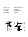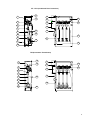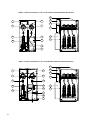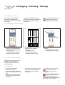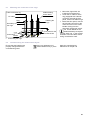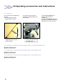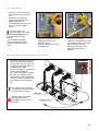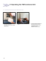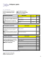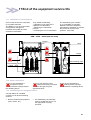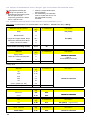
1
MEDIUM VOLTAGE SWITCHGEAR
FLUOKIT M24+
Installation
Commissioning
Operation
Maintenance
Instructions
T&D
Table of Contents
1
AREVA at your service . . . . . . . . . . . . . . . . . . . . . . . . . . . . . . . . . . . . . . . . . . . . . . . . . .
1
1.1
1.2
Our Service Unit: our specialists, and suitably adapted services... . . . . . . . . . . . . . . . . . . . . . . . . . . . .
AREVA T&D Training Centre: your training partner . . . . . . . . . . . . . . . . . . . . . . . . . . . . . . . . . . . . . . . . .
1
1
2
With regards to this User Manual . . . . . . . . . . . . . . . . . . . . . . . . . . . . . . . . . . . . . . . .
2
2.1
2.2
2.3
2.4
2.5
2.6
2.7
2.8
Eco-design concept and revalorization of the materials used . . . . . . . . . . . . . . . . . . . . . . . . . . . . . . . . .
Responsibilities . . . . . . . . . . . . . . . . . . . . . . . . . . . . . . . . . . . . . . . . . . . . . . . . . . . . . . . . . . . . . . . . . . . . . . . .
Reminder concerning normal service conditions (in accordance with IEC 60694) . . . . . . . . . . . . . . .
* Permissible ambient temperature . . . . . . . . . . . . . . . . . . . . . . . . . . . . . . . . . . . . . . . . . . . . . . . . . . . . . . .
* Installation altitude . . . . . . . . . . . . . . . . . . . . . . . . . . . . . . . . . . . . . . . . . . . . . . . . . . . . . . . . . . . . . . . . . . . .
* Atmospheric pollution . . . . . . . . . . . . . . . . . . . . . . . . . . . . . . . . . . . . . . . . . . . . . . . . . . . . . . . . . . . . . . . . .
* Permissible atmospheric pollution . . . . . . . . . . . . . . . . . . . . . . . . . . . . . . . . . . . . . . . . . . . . . . . . . . . . . . .
Special instructions for operations and any intervention on energized equipment . . . . . . . . . . . . . . .
Other technical notices to be consulted . . . . . . . . . . . . . . . . . . . . . . . . . . . . . . . . . . . . . . . . . . . . . . . . . . .
Tools and products (not supplied) required for the operations described in this user manual . . . . . .
Conventional symbols . . . . . . . . . . . . . . . . . . . . . . . . . . . . . . . . . . . . . . . . . . . . . . . . . . . . . . . . . . . . . . . . . .
Tightening torques for standard assemblies (bolt + nut) . . . . . . . . . . . . . . . . . . . . . . . . . . . . . . . . . . . . .
2
2
2
2
2
2
2
3
3
3
4
4
3
Presentation . . . . . . . . . . . . . . . . . . . . . . . . . . . . . . . . . . . . . . . . . . . . . . . . . . . . . . . . . . .
5
3.1
3.2
3.3
Description . . . . . . . . . . . . . . . . . . . . . . . . . . . . . . . . . . . . . . . . . . . . . . . . . . . . . . . . . . . . . . . . . . . . . . . . . . .
Dimensions and approximate weight of the functional units . . . . . . . . . . . . . . . . . . . . . . . . . . . . . . . . . .
Presentation of the Functional Units . . . . . . . . . . . . . . . . . . . . . . . . . . . . . . . . . . . . . . . . . . . . . . . . . . . . . .
5
5
6
4
Packaging - Handling - Storage . . . . . . . . . . . . . . . . . . . . . . . . . . . . . . . . . . . . . . . . . .
9
4.1
4.2
4.3
4.4
4.5
4.6
4.7
4.8
4.9
4.10
4.11
Transport - Delivery . . . . . . . . . . . . . . . . . . . . . . . . . . . . . . . . . . . . . . . . . . . . . . . . . . . . . . . . . . . . . . . . . . . .
Packaging of Functional Units . . . . . . . . . . . . . . . . . . . . . . . . . . . . . . . . . . . . . . . . . . . . . . . . . . . . . . . . . . .
The accessories package . . . . . . . . . . . . . . . . . . . . . . . . . . . . . . . . . . . . . . . . . . . . . . . . . . . . . . . . . . . . . . .
Acceptance . . . . . . . . . . . . . . . . . . . . . . . . . . . . . . . . . . . . . . . . . . . . . . . . . . . . . . . . . . . . . . . . . . . . . . . . . . .
Location of the technical data plates . . . . . . . . . . . . . . . . . . . . . . . . . . . . . . . . . . . . . . . . . . . . . . . . . . . . . .
Handling . . . . . . . . . . . . . . . . . . . . . . . . . . . . . . . . . . . . . . . . . . . . . . . . . . . . . . . . . . . . . . . . . . . . . . . . . . . . . .
Storage conditions . . . . . . . . . . . . . . . . . . . . . . . . . . . . . . . . . . . . . . . . . . . . . . . . . . . . . . . . . . . . . . . . . . . . .
Intervention levels . . . . . . . . . . . . . . . . . . . . . . . . . . . . . . . . . . . . . . . . . . . . . . . . . . . . . . . . . . . . . . . . . . . . .
Specific instructions for storage of less than 6 months . . . . . . . . . . . . . . . . . . . . . . . . . . . . . . . . . . . . . .
Specific instructions for storage from 6 to 12 months . . . . . . . . . . . . . . . . . . . . . . . . . . . . . . . . . . . . . . .
Specific instructions for storage from 12 to 24 months . . . . . . . . . . . . . . . . . . . . . . . . . . . . . . . . . . . . . .
9
9
9
9
10
10
11
11
11
11
11
5
Unpacking and installation of the equipment . . . . . . . . . . . . . . . . . . . . . . . . . . . . .
12
5.1
5.2
5.3
5.4
5.5
5.6
Type of Building Structural Work . . . . . . . . . . . . . . . . . . . . . . . . . . . . . . . . . . . . . . . . . . . . . . . . . . . . . . . . .
Surface flatness values . . . . . . . . . . . . . . . . . . . . . . . . . . . . . . . . . . . . . . . . . . . . . . . . . . . . . . . . . . . . . . . . .
Unpacking the Functional Units . . . . . . . . . . . . . . . . . . . . . . . . . . . . . . . . . . . . . . . . . . . . . . . . . . . . . . . . . .
Handling the Functional Unit . . . . . . . . . . . . . . . . . . . . . . . . . . . . . . . . . . . . . . . . . . . . . . . . . . . . . . . . . . . .
Installation of a switchboard . . . . . . . . . . . . . . . . . . . . . . . . . . . . . . . . . . . . . . . . . . . . . . . . . . . . . . . . . . . . .
Revalorizing packaging waste . . . . . . . . . . . . . . . . . . . . . . . . . . . . . . . . . . . . . . . . . . . . . . . . . . . . . . . . . . .
12
12
12
12
13
13
i
6
Installation . . . . . . . . . . . . . . . . . . . . . . . . . . . . . . . . . . . . . . . . . . . . . . . . . . . . . . . . . . . . .
14
6.1
6.2
6.3
6.4
6.5
6.6
6.7
6.8
Installation of the Functional Units . . . . . . . . . . . . . . . . . . . . . . . . . . . . . . . . . . . . . . . . . . . . . . . . . . . . . . . .
Fitting each of the Functional Units in place . . . . . . . . . . . . . . . . . . . . . . . . . . . . . . . . . . . . . . . . . . . . . . .
Fixing the Functional Units . . . . . . . . . . . . . . . . . . . . . . . . . . . . . . . . . . . . . . . . . . . . . . . . . . . . . . . . . . . . . .
Connection of the inter-Functional Units grounding circuit . . . . . . . . . . . . . . . . . . . . . . . . . . . . . . . . . . .
Earthing the switchboard . . . . . . . . . . . . . . . . . . . . . . . . . . . . . . . . . . . . . . . . . . . . . . . . . . . . . . . . . . . . . . . .
Standard busbar connections . . . . . . . . . . . . . . . . . . . . . . . . . . . . . . . . . . . . . . . . . . . . . . . . . . . . . . . . . . . .
Connection of a 1250 A busbar . . . . . . . . . . . . . . . . . . . . . . . . . . . . . . . . . . . . . . . . . . . . . . . . . . . . . . . . . .
Connection between 630 A and 1250 A busbar . . . . . . . . . . . . . . . . . . . . . . . . . . . . . . . . . . . . . . . . . . . .
14
14
14
15
15
16
17
17
7
Connection of the HV cables . . . . . . . . . . . . . . . . . . . . . . . . . . . . . . . . . . . . . . . . . . . .
18
7.1
7.2
7.3
7.4
7.5
7.6
7.7
7.8
7.9
7.10
7.11
7.12
Preparation of the HV cable connections . . . . . . . . . . . . . . . . . . . . . . . . . . . . . . . . . . . . . . . . . . . . . . . . . .
Connection instructions . . . . . . . . . . . . . . . . . . . . . . . . . . . . . . . . . . . . . . . . . . . . . . . . . . . . . . . . . . . . . . . . .
Preparation of the cables . . . . . . . . . . . . . . . . . . . . . . . . . . . . . . . . . . . . . . . . . . . . . . . . . . . . . . . . . . . . . . .
Connection of an IS Functional Unit . . . . . . . . . . . . . . . . . . . . . . . . . . . . . . . . . . . . . . . . . . . . . . . . . . . . . .
Connection of a PF or PFA Functional Unit . . . . . . . . . . . . . . . . . . . . . . . . . . . . . . . . . . . . . . . . . . . . . . . .
Clamping the cables and connection of the screen braids . . . . . . . . . . . . . . . . . . . . . . . . . . . . . . . . . . .
Connection in a PGC or IS Functional Unit equipped with current transformers . . . . . . . . . . . . . . . . .
Earthing the earthing screen braids for the cables . . . . . . . . . . . . . . . . . . . . . . . . . . . . . . . . . . . . . . . . .
Fitting the fuses on to the PF-PFA Functional Units . . . . . . . . . . . . . . . . . . . . . . . . . . . . . . . . . . . . . . . . .
The sensors (rings) for fault detection and signalling . . . . . . . . . . . . . . . . . . . . . . . . . . . . . . . . . . . . . . . .
Mounting the rings . . . . . . . . . . . . . . . . . . . . . . . . . . . . . . . . . . . . . . . . . . . . . . . . . . . . . . . . . . . . . . . . . . . . .
Special instructions at the end of the connections . . . . . . . . . . . . . . . . . . . . . . . . . . . . . . . . . . . . . . . . . .
18
19
19
20
20
21
21
21
22
23
23
23
8
Connection of the low voltage circuits . . . . . . . . . . . . . . . . . . . . . . . . . . . . . . . . . . .
24
8.1
8.2
8.3
8.4
8.5
Motorised remote control interface for the switches [option] . . . . . . . . . . . . . . . . . . . . . . . . . . . . . . . . . .
Foolproofing of the remote control connector [Public Distribution] . . . . . . . . . . . . . . . . . . . . . . . . . . . . .
Identification and function of the pins [Public Distribution] . . . . . . . . . . . . . . . . . . . . . . . . . . . . . . . . . . . .
Connection of the "Metering" low voltage wiring to the PGB Functional Unit . . . . . . . . . . . . . . . . . . .
Connection of the "Metering" low voltage wiring to the TM Functional Unit . . . . . . . . . . . . . . . . . . . .
24
24
24
25
25
9
Double shunt layout function . . . . . . . . . . . . . . . . . . . . . . . . . . . . . . . . . . . . . . . . . . .
26
9.1
9.2
Mounting and connection of the rings . . . . . . . . . . . . . . . . . . . . . . . . . . . . . . . . . . . . . . . . . . . . . . . . . . . . .
Commissioning the double shunt layout . . . . . . . . . . . . . . . . . . . . . . . . . . . . . . . . . . . . . . . . . . . . . . . . . . .
27
27
10
Operating accessories and instructions . . . . . . . . . . . . . . . . . . . . . . . . . . . . . . . . .
28
10.1
10.2
10.3
10.4
10.5
10.6
Reminders . . . . . . . . . . . . . . . . . . . . . . . . . . . . . . . . . . . . . . . . . . . . . . . . . . . . . . . . . . . . . . . . . . . . . . . . . . . .
Operation of a Functional Unit equipped with a C410-C410S-C410M control . . . . . . . . . . . . . . . . . . .
Operation of a Functional Unit equipped with a C430-C430M control . . . . . . . . . . . . . . . . . . . . . . . . . .
Operation of a Functional Unit equipped with a C440-C440M control . . . . . . . . . . . . . . . . . . . . . . . . . .
Testing the cables . . . . . . . . . . . . . . . . . . . . . . . . . . . . . . . . . . . . . . . . . . . . . . . . . . . . . . . . . . . . . . . . . . . . .
Installing the removable earthing switch device . . . . . . . . . . . . . . . . . . . . . . . . . . . . . . . . . . . . . . . . . . . .
28
28
28
28
29
29
11
Operation of the TM Functional Unit . . . . . . . . . . . . . . . . . . . . . . . . . . . . . . . . . . . . .
30
11.1 Operating manoeuvres for the TM Functional Unit . . . . . . . . . . . . . . . . . . . . . . . . . . . . . . . . . . . . . . . . . .
30
ii
Table of Contents
12
Operation of the PGB and PGC Functional Units . . . . . . . . . . . . . . . . . . . . . . . . .
31
12.1
12.2
12.3
12.4
12.5
Opening of the downstream earthing switch (only for PGC) . . . . . . . . . . . . . . . . . . . . . . . . . . . . . . . . . .
Opening the upstream earthing switch . . . . . . . . . . . . . . . . . . . . . . . . . . . . . . . . . . . . . . . . . . . . . . . . . . . .
Closing the earthing switch . . . . . . . . . . . . . . . . . . . . . . . . . . . . . . . . . . . . . . . . . . . . . . . . . . . . . . . . . . . . .
Closing the circuit breaker . . . . . . . . . . . . . . . . . . . . . . . . . . . . . . . . . . . . . . . . . . . . . . . . . . . . . . . . . . . . . .
De-energizing a PGB or PGC Functional Unit . . . . . . . . . . . . . . . . . . . . . . . . . . . . . . . . . . . . . . . . . . . . . .
31
31
32
32
32
13
Locking-out and locking operations . . . . . . . . . . . . . . . . . . . . . . . . . . . . . . . . . . . . .
33
13.1 Mechanical function interlocks . . . . . . . . . . . . . . . . . . . . . . . . . . . . . . . . . . . . . . . . . . . . . . . . . . . . . . . . . . .
13.2 Locking-out by padlock (not supplied) . . . . . . . . . . . . . . . . . . . . . . . . . . . . . . . . . . . . . . . . . . . . . . . . . . . . .
13.3 Locking-out by keylocks . . . . . . . . . . . . . . . . . . . . . . . . . . . . . . . . . . . . . . . . . . . . . . . . . . . . . . . . . . . . . . . .
33
33
34
14
Commissioning . . . . . . . . . . . . . . . . . . . . . . . . . . . . . . . . . . . . . . . . . . . . . . . . . . . . . . . .
35
14.1
14.2
14.3
14.4
14.5
14.6
14.7
14.8
Reminders . . . . . . . . . . . . . . . . . . . . . . . . . . . . . . . . . . . . . . . . . . . . . . . . . . . . . . . . . . . . . . . . . . . . . . . . . . . .
Inventory of tools and accessories on completion of work . . . . . . . . . . . . . . . . . . . . . . . . . . . . . . . . . . .
Pre-commissioning information . . . . . . . . . . . . . . . . . . . . . . . . . . . . . . . . . . . . . . . . . . . . . . . . . . . . . . . . . .
Final checks before commissioning . . . . . . . . . . . . . . . . . . . . . . . . . . . . . . . . . . . . . . . . . . . . . . . . . . . . . .
Energizing the Incoming" Functional Unit . . . . . . . . . . . . . . . . . . . . . . . . . . . . . . . . . . . . . . . . . . . . . . . . .
Energizing a second 'Incoming' Functional Unit, supplied from the same source . . . . . . . . . . . . . . . .
Control of phase balance with a VPIS voltage presence indicator (in accordance with IEC 61958)
Energizing the switchboard . . . . . . . . . . . . . . . . . . . . . . . . . . . . . . . . . . . . . . . . . . . . . . . . . . . . . . . . . . . . .
35
35
35
35
36
36
36
36
15
Maintenance . . . . . . . . . . . . . . . . . . . . . . . . . . . . . . . . . . . . . . . . . . . . . . . . . . . . . . . . . . .
37
15.1
15.2
15.3
15.4
15.5
15.6
15.7
15.8
15.9
Levels of maintenance . . . . . . . . . . . . . . . . . . . . . . . . . . . . . . . . . . . . . . . . . . . . . . . . . . . . . . . . . . . . . . . . . .
Preventive maintenance for the control mechanisms . . . . . . . . . . . . . . . . . . . . . . . . . . . . . . . . . . . . . . . .
Preventive maintenance of the functional units . . . . . . . . . . . . . . . . . . . . . . . . . . . . . . . . . . . . . . . . . . . . .
Systematic preventive maintenance . . . . . . . . . . . . . . . . . . . . . . . . . . . . . . . . . . . . . . . . . . . . . . . . . . . . . .
Greasing the contact surfaces . . . . . . . . . . . . . . . . . . . . . . . . . . . . . . . . . . . . . . . . . . . . . . . . . . . . . . . . . . .
Corrective maintenance . . . . . . . . . . . . . . . . . . . . . . . . . . . . . . . . . . . . . . . . . . . . . . . . . . . . . . . . . . . . . . . .
Replacement of the three MV fuses . . . . . . . . . . . . . . . . . . . . . . . . . . . . . . . . . . . . . . . . . . . . . . . . . . . . . .
Replacement of the VDS (Voltage Detection System - LV capacitors) . . . . . . . . . . . . . . . . . . . . . . . . .
Possible anomalies and remedies . . . . . . . . . . . . . . . . . . . . . . . . . . . . . . . . . . . . . . . . . . . . . . . . . . . . . . . .
37
37
37
37
38
38
38
39
40
16
Spare parts . . . . . . . . . . . . . . . . . . . . . . . . . . . . . . . . . . . . . . . . . . . . . . . . . . . . . . . . . . . .
41
16.1
16.2
16.3
16.4
The spare part . . . . . . . . . . . . . . . . . . . . . . . . . . . . . . . . . . . . . . . . . . . . . . . . . . . . . . . . . . . . . . . . . . . . . . . . .
Identification of the equipment (See § 4.5) . . . . . . . . . . . . . . . . . . . . . . . . . . . . . . . . . . . . . . . . . . . . . . . .
Storage conditions . . . . . . . . . . . . . . . . . . . . . . . . . . . . . . . . . . . . . . . . . . . . . . . . . . . . . . . . . . . . . . . . . . . . .
Maintenance consumables . . . . . . . . . . . . . . . . . . . . . . . . . . . . . . . . . . . . . . . . . . . . . . . . . . . . . . . . . . . . . .
41
41
42
42
iii
17
End of the equipment service life . . . . . . . . . . . . . . . . . . . . . . . . . . . . . . . . . . . . . . . .
43
17.1
17.2
17.3
17.4
17.5
Valorization of the equipment . . . . . . . . . . . . . . . . . . . . . . . . . . . . . . . . . . . . . . . . . . . . . . . . . . . . . . . . . . . .
Safety instructions . . . . . . . . . . . . . . . . . . . . . . . . . . . . . . . . . . . . . . . . . . . . . . . . . . . . . . . . . . . . . . . . . . . . .
Dismantling of the equipment service . . . . . . . . . . . . . . . . . . . . . . . . . . . . . . . . . . . . . . . . . . . . . . . . . . . . .
Specific recommendations for the "SF6 gas" type circuit breaker and load break switch . . . . . . . . .
Breakdown and valorization of the materials used for PGB (See § 17.1) . . . . . . . . . . . . . . . . . . . . . . .
43
43
43
44
44
18
Notes . . . . . . . . . . . . . . . . . . . . . . . . . . . . . . . . . . . . . . . . . . . . . . . . . . . . . . . . . . . . . . . . . .
45
iv
1 AREVA at your service
Operation and maintenance may
only be carried out by personnel
who have received suitable
authorisation for the operations and
manĹuvres they are responsible
for performing.
1.1
If this is not the case, please refer
to our Service Unit or to our
Training Centre.
All locking-out operations must be
performed according to the
Our Service Unit: our specialists, and suitably adapted services...
Guarantee extension contracts
in relation to the selling of new
equipment,
Supervision of HVA switchgear
installations,
Technical advice, diagnoses of the
facilities, expertise,
Maintenance contracts adapted
to the operational constraints,
Systematic or conditional
preventive maintenance,
Corrective maintenance in case of
partial or complete failure,
Supply of spare parts,
Overhauling of equipment and
requalification of installations in
order to benefit from new
technologies and extend the life of
your switchgear by limited
investments.
F
F
F
F
F
F
F
F
1.2
F
"General Safety Instructions
booklet for Electrical Applications"
UTE C 18 510
(or its equivalent outside FRANCE).
Contact the AREVA Service Unit for diagnoses and advice:
Working hours
Phone No: 33 (0)3 85 29 35 00
Fax:
33 (0)3 85 29 36 30
or
33 (0)3 85 29 36 43
7 days per week / 24hours per day
Free phone No: 0 800 40 27 62
AREVA T&D Training Centre: your training partner
A wide field of expertise:
- study and design of networks
and installations,
- operation and maintenance of
LV, HVA and HVB equipment,
- application themes (electrical
generating sets, diesel motors
etc.),
- electrical safety enabling the
employer to give suitable
authorisation to the people in
charge of the operations and
interventions on electrical
equipment,
F
F
F
F
training sessions in our centres
or on site, defined according to
your objectives and constraints,
qualified trainers and experts in
their field,
practical work on real machines
which represent more than 50%
of the training period,
an FIEEC Quality Training
Charter member organisation
and certified ISO 9001 version
2000.
Faced with the direct and indirect training costs of the operational
stoppages and shutdown, training is a real investment
AREVA T&D Training Centre
130, Rue Léon Blum - BP 1321 - F-69611 Villeurbanne Cedex
Tel.: +33 (0)4 72 68 33 86 Fax: 33 (0)4 72 68 35 17 E-mail: [email protected]
1
2 With regards to this notice
© - AREVA- 2004. AREVA, the
AREVA logo and their figurative
forms are AREVA registered
2.1
N° 98-638 of 20 July 1998,
concerning the account that is
taken of environmental
requirements.
accordance with the indications
given in this document, must be
observed.
- any possible aggressive climatic
conditions (humidity, pollution, etc.)
acting in the immediate
environment of the materials that
are neither suitably adapted nor
protected for these effects.
This user manual does not list the
locking-out procedures that must
be applied. The interventions
described are carried out on
de-energized equipment (in the
course of being installed) or locked
out (non operational).
Responsibilities
Our devices are quality controlled
and tested at the factory in
accordance with the standards and
the regulations currently in force.
Apparatus efficiency and apparatus
life depend on the compliance with
the installation, commissioning and
operation instructions described in
this user manual. Non respect of
these instructions is likely to
invalidate any guarantee.
Local requirements especially
about safety and which are in
2.3
copyright or not, belong to their
respective holders.
Eco-design concept and revalorization of the materials used
The design and manufacture of our
packaging are both in conformity
with the French government decree
2.2
trademarks. The other brand
names mentioned within this
document, whether they be
AREVA declines any responsibility
for the consequences:
- due to the non respect of the
recommendations in this manual
which make reference to the
international regulations in force.
- due to the non respect of the insĆ
tructions by the suppliers of cables
and connection accessories during
installation and fitting operations,
Reminder concerning normal service conditions (in accordance with IEC 60694)
* Permissible ambient temperature
The ambient air temperature should
be comprised between - 5°C and
+ 40° C.
The mean measured value for a 24
hour period must not exceed 35°C.
* Installation altitude
HV equipment are defined in
accordance with European
Standards and can be used up to
an altitude of 1,000 m.
Beyond this, account must be
taken of the decrease in dielectric
withstand.
For these specific cases, contact
the AREVA Sales Department
* Atmospheric pollution
The ambient air must not contain
any dust particles, fumes or smoke,
corrosive or flammable gases,
vapours or salts.
* Permissible atmospheric humidity level
The average atmospheric relative
humidity level measured over a
24-hour period must not exceed
95%.
The average atmospheric relative
humidity value measured over a
period of one month must not
exceed 90 %.
The average water vapour pressure
over a period of 24 hours must not
exceed 22 mbar.
The average water vapour pressure
over a period of one month must
not exceed 18 mbar.
2
Condensation may appear in case
of any sharp variation in temperaĆ
ture, due to excessive ventilation, a
high atmospheric humidity level or
the presence of hot air. This
condensation can be avoided by an
appropriate layout of the room or of
the building (suitably adapted ventiĆ
lation, air driers, heating etc.).
Whenever the humidity level is
higher than 95 %, we recommend
that you take appropriate corrective
2.4
Particular instructions for operation and intervention with energized equipment
When commissioning and
operating the equipment under
normal conditions, the General
Safety Instructions for electrical
applications must be respected,
(protective gloves, insulating stool,
etc.), as well as the operating
instructions.
2.5
F
F
F
F
F
F
F
2.6
measures. For any assistance or
advice, contact the AREVA
After-Sales department (See § 1.1).
All manipulations must be
completed once started.
The durations for carrying out the
operations mentioned in the
maintenance tables are given
purely as an indication and depend
on the conditions on-site.
Other technical notices to be consulted
AMTNoT100-02
AMTNoT101-02
AMTNoT102-02
AMTNoT017-02
AMTNoT055-02
AMTNoT099-02
AMTNoT093-02
C410-C410M Mechanical controls
Operation - Maintenance
C430-C430M Mechanical controls
Operation - Maintenance
C440-C440M Mechanical controls
Operation - Maintenance
BLR-BLRM Mechanical controls
Operation - Maintenance
FP Circuit Breaker
Installation - Commissioning - Operation - Maintenance
Standard mechanical interlocking by keylocks
Civil Engineering Guide
Tools and products (not supplied) required for the operations described in this notice
- Cutter
ÎÎÎ
- Crowbar
- Flat blade spanners size 10 ; 13 ; 16 ; 18 & 19 mm
- Ratchet handle + extension with socket sizes 10 ; 13 ; 16 & 18 mm
- Torque wrench with sockets size 10 ; 13 ; 18 mm
- Magnetic screwdriver + 3mm Allen key tip
- Flat headed screwdriver
- Allen key for sizes 4 ; 5 ; 6 ; 8 mm
Product code
- A dry cloth
- Solvent (di-electric resistance > 30kV), excluding chlorine based products
- Electrolube 2 GX - electrical contact grease from Comindus
22
3
2.7
2.8
Symbols & conventions
06
- Code for a product
recommended and
marketed by AREVA
1.6
- Torque value
Example: 1.6 daN.m
10
- Mark corresponding to a key
CAUTION! Remain vigilant!
Precautions to beCAUTION
taken in order to
avoid any accident or injury
FORBIDDEN! Do not do it!
The compliance with this indication is
compulsory, non compliance with this
stipulation may damage the equipment.
INFORMATION - ADVICE
Your attention is drawn to a specific
point or operation.
Tightening torque values for standard assemblies (nut + bolt)
Threaded fasteners without grease:
assembly with ungreased washers.
Threaded fasteners with grease:
mounted with the washer greased.
Use grease referenced:
01
Zinc plated steel fasteners without grease (daN.m)
Dimensions
4
Stainless steel fasteners with
grease (daN.m)
Class 6.8
Class 8.8
A2-70
M6
0.7
0.9
0.7
M8
1.6
2.1
1.6
M 10
3.2
4.3
3.2
M 12
5
6.6
5
M 14
8.7
11.6
8.7
M 16
13.4
17.9
13.4
M 20
26.2
35
26.2
3 Presentation
3.1
Description
FLUOKIT M24+ Functional Units
are designed for indoor use.
The range meets the definition of
switchgear of the type "under
compartmentalised metal casing",
in compliance with the design and
construction rules mentioned in the
Standards IEC 62271-200 and
IEC 60466.
3.2
Each Functional Unit is divided into
4 separate compartments,
separated by metal partitions:
- Telecontrol compartment,
- Busbar,
- Breaker switchgear or
isolation switchgear, with an
operating lever,
- Cables.
Dimensions and approximate weight of the Functional Units
Functional Units
IS - PF - PFA
TM
PGB - PGC
Width (mm)
375
500
375
500
750
875
1125
Overall Depth (mm)
1026
1026
1026
1026
1100
1100
1100
Height (mm)
1610
1610
1610
1610
1610
1610
1610
with deflector or LV box on the roof
1950
1950
1950
1950
1950
1950
1950
Approximate weight (kg)
115
125
195
210
410
460
510
standard
5
3.3
Presentation of the Functional Units
0
-Ą1
-Ą2
-Ą3
-Ą4
-Ą5
-Ą6
-Ą7
-Ą8
-Ą9
-Ą10
-Ą11
-Ą12
-Ą13
-Ą14
Key
Busbar connection plates
ISR switch-disconnector
Upstream Earthing Switch
Upper fuse support shell
Cable connections shell
MV Fuse
Capacitive insulator
Lower fuse holder shell
Downstream Earthing Switch
Base plate in 4 elements
LV casing
Exhaust shaft
Overpressure valves
Earthing bar connection point
-Ą15
-Ą16
-Ą17
-Ą18
-Ą19
-Ą20
-Ą21
-Ą22
-Ą23
-Ą24
-Ą25
-Ą26
-Ą27
Access panel to the busbars
Mechanical control mechanism for the switch
Circuit breaker mechanical control mechanism (BLR)
Voltage presence luminous indicators or interface for
Voltage Detection System
Inspection window for checking the earthing switch position
Test pin for fitting the earthing block
Access panel to the cable compartment
ES location (LV capacitors)
Voltage transformers
Auxiliary contacts
Current transformers
Cable connection lugs
FP circuit breaker with interruption under SF6 gas
IS (Switch-Disconnector)
1
14
13
2
5
22
11
16
3
7
15
20
13
12
18
19
13
13
21
10
13
6
13
PF - PFA (Combined Fuse Protection)
1
14
13
2
20
19
22
13
8
9
12
18
4
13
13
11
16
3
6
15
7
21
13
10
TM (Instrument Transformer)
1
14
13
2
11
13
15
12
16
3
4
6
20
19
13
21
8
23
24
0
7
PGB + current transformers + FP circuit breaker (General Busbar Protection)
12
1
11
1
15
2
2
16
27
13
17
13
21
25
13
25
PGC + current transformers + FP circuit breaker (General Cable Protection)
12
1
1
11
15
2
2
3
9
27
25
17
13
21
13
7
26
13
8
16
4 Packaging - Handling - Storage
4.1
Transport - Delivery
The conditions and methods of
transport are defined with the
customer, at the time of processing
the contract.
4.2
Packaging is dependent on the
conditions of transport, storage and
the nature of the product being
transported.
Packaging of Functional Units
ÁÁÁÁÁÁÁ
ËËË
ËË
ËË
ËË
ËË
ËËË
ÁÁÁÁÁÁÁ
ËË
ËË
ËË
ËË
ËËËËËËË
ËËËË
ËËË
ËË
ËË
ËË
ËË
ËËË
ËË
ËË
ËË
ËË
ËËË
ËË
ËË
ËË
ËË
ÁÁÁÁÁÁÁ
ËËË
ËË
ËË
ËË
ËË
ËËË
ËË
ËË
ËË
ËË
ËËË
ËË
ËË
ËË
ËË
ËËË
ËË
ËË
ËË
ËË
ÁÁÁÁÁÁÁ
ËËË
ËË
ËË
ËË
ËË
ÁÁÁÁÁÁÁ
ËËËËËËË
ËËËË
ÉÉÉÉÉÉÉ
F
4.3
The Functional Unit must be
handled and transported
vertically (position shown below).
The packaging of a Functional
Unit for road and rail transport:
- fixed on to a wooden pallet or
bound by hoops,
- covered by plastic sheeting,
- protection of the front face.
F
The packaging of a Functional
Unit for air and maritime
transport:
- heat-sealed cover
with desiccant sachets,
- packed in wooden crates.
1
2
F
Status of the equipment on
delivery:
1. Load break switch "Open"
2. Earthing switch "Closed".
The accessories package
Contains all elements required for
locating and connecting the
Functional Units to busbar and
cable connections.
4.4
F
F
F
Reception
Ensure that the material
delivered is all there.
Carry out a visual inspection of
the Functional Units and moving
parts.
Verify that the accessories are
present in accordance with the
attached list.
F
Check the characteristics shown
on the name and rating plates,
in relation to the initial order
(voir § 4.5).
In the event of an anomaly,
inform and make the
necessary reserves with the
transporter.
The Functional Unit must
remain on its base, within its
original packaging during any
storage period and until it arrives at
the location of its installation.
9
4.5
Location of the technical data plates
1
2
1
3
F
F
F
4.6
2
3
1 - Technical characteristics.
2 - Identification plate.
3 - Allocation to AMT customer
(references, order number,
etc.).
Handling
ÌÌÌ
ÎÎÎ
ÎÎÎ
ÌÌÌ
ÎÎÎ
ÌÌÌ
ÎÎÎ
ÌÌÌ
ÎÎÎ
ÌÌÌ
ÎÎÎ
ÌÌÌ
ÎÎÎ
ÌÌÌ
ÎÎÎ
ÌÌÌ
ÎÎÎ
F
F
Road and Rail packaging
(500 kg max.): using a fork lift
truck.
It is imperative to ensure that
the forks of the truck are fully
engaged throughout the entire
width of the Functional Unit
10
F
F
Packaging for air and maritime
transport: Depending on the
weight indicated on the crate.
It is imperative that the forks of
the truck are fully engaged
throughout the entire width of
the crate.
1m min.
F
F
Pass 2 slings, each one
supporting 1,000 kg .
Remove the lifting parts after
handling
(4 screws, 13 mm spanner).
4.7
Storage conditions
Ensure that the material is suitably
packaged for the requirements of
the planned storage period.
Preserve the equipment in its intact
original factory packaging .
ÌÌÌÌÌÌÌ
ÌÌÌÌÌÌÌ
ÌÌÌÌÌÌÌ
The site chosen for storage must be
capable of protecting the products
against possible damage due to
deterioration agents, such as:
- Water
- Water vapour
- Saline atmosphere
- All types of pollution
- Micro organisms.
ÁÁÁÁ
Ë
ËË
Ë
ËË
ËË
Ë
ËË
Ë
ËË
ËË
Ë
ËË
Ë
ËË
ËË
ÁÁÁÁ
ËËË
ËË
ËËË
Ë
ËË
Ë
ÉÉÉÁÁÁÁ
ËËË
ËË
ÁÁÁÁ
ËËË
ËË
ËË
+50° C
- 25° C
Contact AREVA for any
derogations to these criteria
4.8
Ensure that there is a total absence
of aggressive vapours [e.g. Sulphur
Dioxide (SO2)].
Avoid leaving the material where it
is likely to be subjected to large,
sudden temperature changes.
Intervention levels
Descrip tion
Operations carried out by the Customer
Levels
1
Operations requiring specific training, carried out by an agreed third party
2
Work to be carried out exclusively by AREVA
4.9
3
Specific recommendations for storage durations of less than 6 months
. Packaged under a plastic covering
1
2
3
Periodically carry out an inspection of the packaging
X X
X
When unpacking, check the mechanical operation by carrying out about ten operations*
X X
X
. Protected by a heat-welded sheet, with desiccant sachets
1
2
3
Periodically carry out an inspection of the packaging (check that, among other things, there are no holes)
X X
X
When unpacking:
-
X
X
-
X
X
. Protected by a heat-welded sheet, with a method of replacing the desiccant sachets
1
2
3
Periodically carry out an inspection of the packaging (check that, among other things, there are no
holes)
X X
X
Periodically replace the desiccant sachets
X X
X
On removing the packaging: - light maintenance work
-
-
X
- check the operation of the switchgear by carrying out several operations*
-
-
X
- test the min. threshold level (AC, 85% rated Un; DC, 70% of Un ) for the electrical operation of the coils
-
-
X
4.10 Specific recommendations for storage durations of between 6 and 12 months
- check the operation of the switchgear by carrying out several operations*
- test the min. threshold level (AC, 85% rated Un; DC, 70% of Un ) for the electrical operation of the coils
4.11 Specific recommendations for storage durations of between 12 and 24 months
* The pressure for an SF6 circuit breaker having travelled by air must be re-established
to its rated value before any mechanical operation test.
11
5 Unpacking and installing the equipment
5.1
Type of Civil Engineering
The installation of a switchboard
requires a sufficiently flat and even
concrete structure.
5.2
The dressing of a top coat of
cement using a rule should
eliminate any surface irregularities.
A layout on iron supports for
levelling off is ideal as they will also
serve as a guide for the adjustment
of the cement top coat.
Surface evenness values
Overall evenness : A 2m rule,
moved along the base should not
highlight any irregularity of greater
than 5mm.
5.3
Local evenness : A 20 cm rule,
moved along the base should not
highlight any irregularity of greater
than 2 mm.
Unpacking the Functional Units
Proceed with unpacking the
Functional Units only where they are
to be installed on site.
5.4
Tools required:
- Cutter for road and rail
transport packaging
- Crowbar for air and sea
transport packaging.
Use suitable protective gloves for
any handling operation.
Handling the Functional Unit
2
1
4 screws
F
F
Remove the protective plastic
cover.
Open the front panel:
1 - lift the panel
2 - pull the panel towards you.
Mark each panel in
accordance with the
corresponding Functional Unit
For the PGB and PGC
Functional Units, remove the
wooden base without extracting the
circuit breaker.
12
F
F
Remove the 4 fixing screws
(16 mm spanner) from the
wooden base.
Free the Functional Unit.
F
Place the Functional Unit on the
ground.
1 m min.
F
Four fixed slinging points are
provided for on the roof of each
Functional Unit.
F
F
These lifting lugs
are to be removed when
the Functional Units are in the
immediate proximity of their
definitive installation.
5.5
F
F
Slide the Functional Unit along,
using three cylindrical rollers of
30 mm min. diameter.
Thus moving it to its final
installation place.
Installation of a switchboard
Please refer to the instructions in
the Civil Engineering Guide
(See § 2.5).
The limits of the civil engineering
layout depends on the type and
quantity of materials to be installed.
5.6
Lift the Functional Unit by
4 slings each one capable of
supporting 1,000 kg.
Respect the minimum carrying
height as shown on the above
diagram.
Position the cells whilst respecting
minimum clearance distances in
front of, behind and to each side of
the switchboard.
Revalorizing packaging waste
After unpacking, the materials
remaining (cover, wooden floor
panel, etc) should be sorted and
sent to the appropriate recycling
services.
13
6 Installation
6.1
Installing Functional Units
For a switchboard consisting of 1 to
8 Functional Units, it is advised that
installation of the materials
6.2
For switchboards using more than
8 units, start by installing the
equipment to the middle of the
switchboard.
Installation of each Functional Unit
For all installation operations it is
advised that you use suitable
protective gloves.
To each far end Functional Unit
fix the blanking off side panel.
F
starts at the end of the room
opposite the entrance.
Organise the arrival of the
Functional Units in accordance with
the single-line diagram.
F
F
F
Position the first Functional Unit.
Verify that it is upright.
Mark out the 6 coupling points.
F
F
F
6.3
Juxtapose the second
Functional Unit.
Align the front panels.
Continue to install the
Functional units whilst repeating
the same checks each time.
Fixing the Functional Units
2 points at the rear (H M12x30
bolts + flat washer Ø 32 exterior) or
by 2 points in the centre for PGB
and PGC.
Interconnect the Functional Units
using the 6 fixing points
(H M8x20 bolts).
60
Fix the Functional Units to the floor,
at two points in front and
70
PGB or PGC
Front face of the switchboard: 3 or X Functional Units
F
4 ground anchoring points
(Fasteners not supplied).
F
F
14
The Functional Units at each end must be anchored to the floor by
their 4 fixing points.
With the exception of specific requirements (seismic resistance,
vibration), it is possible to install just one of the Functional Units out of
two at the rear.
6.4
Connection of the inter-Functional Units grounding circuit
1.5
F
6.5
On the roof of the Functional
Units, position and fix the
earthing circuit bars (M8 washer
+ ES 8 washer + H M8 nut 13 mm spanner).
F
Close-up of the connection.
Earthing the switchboard
The general switchboard earthing
connection to the ground electrode
of the building is made via the
Functional Unit to the extreme right
of the set (viewed from the front).
The copper connecting conductor
must have a minimum cross
section of 25mm2 (fasteners not
supplied).
Remove the plastic blanking
panel to connect the cable.
4.9
4.9
H M12x20 bolts
+ flat washer
+ self locking
washer
+ H M12 nut
F
Connector point for the linkage
cable to the ground electrode.
F
Min. cross-section: 25 mm2
Fit the bolt via the interior of the Functional unit, then attach the cable,
the flat washer, the self-locking washer and finally the HM12 nut
(fasteners not supplied).
15
6.6
Standard busbar connections
No preparation is required for the
contact surfaces. A simple dusting
down should be allowed for.
F
Gain access to the busbar by
removing the first roof panel
(fixing by 7 H M6 screws).
If the storage time has been long,
ensure that there has been no
trace of any knocks or oxidation.
F
Also remove the second panel
(4 H M6x20 screws).
In case of oxidation, lightly brush
the parts with Vaseline, using a
very fine metal brush.
F
The busbar assembly is
accessible, as well as the front
protection panel.
Use the deflector with a captive screw CHC,
M10x35 (8 mm Allen key).
2
F
F
Possibility of dismantling this
panel to have access to the
wires behind the LV box.
F
Standard assembly of the bars
on to the supply terminals.
Connection of the busbars between two Functional Units.
16
F
Standard busbar connection
6.7
Connection of a 1250 A busbar
CHC M10x65 bolts
3 Belleville washers
1250 A Bar
Internal contact
Deflector
Shim
External contact
2
2
Extremity mounting
F
F
F
F
6.8
Standard mounting
Fit the external contact, the internal contact, the 3 Belleville washers then the CHC M10x65 bolt, without
tightening.
Position the 1250 A bars between the two contacts. At each extremity (as shown here), fit a shim in place
of the second bar.
When all of the bars have been fitted, tighten to the indicated torque.
Clip on the extremity deflectors.
Connection between 630 A and 1250 A busbars
H M10 nut
Deflector
3 Belleville washers
Internal contact
1250 A Bar
630 A Bar
Shim
External contact
M12/M10-92 pin
2
Example of a connection
Insulator
F
F
F
F
F
Screw the M12/M10-92 pin into the insulator.
Fit the 630 A bar, the external contact, the internal contact, the 3
Belleville washers then the H M10 nut, without tightening.
Position the 1250 A bars between the two contacts. At each
extremity (as shown opposite), fit a shim in place of the second bar.
When all of the bars have been fitted, tighten to the indicated torque.
Clip on the extremity deflectors.
17
7 Connection of the HV cables
Preparation of the HV cable connections
7.1
F
F
State of the Functional Units after installation: all of the earthing switches
are closed.
Remove and mark the cable access panels in accordance with the
Functional Units.
F
Remove the upper cable
tightening straps
(2 H M8x50 screws).
Top view
Side face view
F
Remove the lower front
cross-bar (2 H M8x20 bolts).
F
F
F
18
Front panel
Floor elements
1
2
1 - Pull the first element towards the front.
2 - Lift up and extract this element.
Proceed in the same way for the following two elements.
Cross-bar
before
removal
7.2
Connection instructions
- Use short cable terminations of the EUI-C type (with shells). They are compulsory for
Functional Units PF - PFA - PGC
- The building of the extremity (other than AREVA supply) must be carried out in
accordance with the manufacturer's instructions.
- The earthing braid for each cable must always exit above the bottom plate and the
clamping collar.
- Leave 40mm of free clearance on the lug barrel for fitting the grounding clamp.
- Ensure the correct orientation of the contact plate before crimping it.
- There must be no stress tensioning the cable.
Never stick any phase markers to the cable end reassemblies
--> decrease in the dielectric strength and degradation over time.
- Never clamp the cable by its cable end.
- Never leave a washer in incompatible material between the lug and the connecting plate.
7.3
Preparation of the cables
ÄÄÄÄ
ÄÄÄÄ
F
F
Pull out each cable from the
opening via the front of the
Functional Unit to make up the
extremity.
Example of a connection
terminating in IS.
F
F
Cut out each grommet to the
diameter of the cable.
F
Fit the grommet on to its cable.
Example of a connection
terminating in PF.
19
7.4
Connection of an IS Functional Unit
0
-Ą1
-Ą2
-Ą3
Legend for § 7.4 and 7.5
Round lug
Deflector
H M12 nut
-Ą4
-Ą5
-Ą6
Belleville Washer
Flat washer
Rectangular lug
-Ą7
-Ą8
Copper spacer (not supplied).
H M8 nut
1
5
7 4.9
2
3 4.9
4
6
th. = 12mm
Ø 28mm
Lift off the deflector, the
H M12 nut and the two washers
for each point.
Connection is made by a round
or rectangular lug.
F
F
Round lug connection
F
F
F
F
F
Ø 13mm
Rectangular lug connection
Fit the lug which must hold firm
against the contact plate.
Fit the flat washer.
Fit the Belleville washer.
Screw in and tighten the nut to
the indicated torque
(18 mm spanner).
Clip on the deflector.
F
F
F
F
F
F
7.5
7
Fit in place the spacer in copper.
Position to hold firm the
rectangular lug.
Fit the flat washer.
Fit the Belleville washer.
Screw in and tighten the nut to
the indicated torque
(18 mm spanner).
Clip on the deflector.
Connection of a PF or PFA Functional Unit
1
5
8 1.5
4
F
F
Connection point.
Begin the connections by the
cable at the back.
PF - PFA Connection
F
F
20
Proceed in the same way as for
the IS unit (§ 7.4).
There is no deflector.
F
F
Remove the H M8 nut and the
two washers from each point.
Connection is made by a
round lug.
7.6
Clamping the cables and connection of the screen braids
F
F
cable < 150 mm2
cable > 150 mm2
F
F
7.7
Place the second floor panel
element.
Fit the grommet firmly.
Adapt the cable terminal straps
(see further on) and tighten the
nuts lightly (13 mm spanner).
F
Repeat these operations for the
other two cables.
Remount the lower front
cross-bar.
For the Functional
Units PF /PFA,
ensure that the cables
exert no traction on the support
cross-bar. Check that after
installation the fuses can be
correctly fitted in place, and that
the contacts are sufficiently
covered (See § 7.9).
Connection in a PGC or IS Functional Unit equipped with current transformers
4.9
3
2
1
F
State on delivery.
F
F
F
7.8
F
1 - Position the lug and the
cable.
2 - Fit the flat washer, then the
self-locking washer.
3 - Screw in and tighten the
H M12 nut to the indicated
torque.
Earthing the screen braids
Connection point for the three
HV cable screen braids.
21
7.9
F
F
F
F
F
Fitting the fuses on to the PF-PFA Functional Units
For a striker fuse of the FN or
FD type (DIN), remove the
protective label.
For FNw and FDw fuses this
label must remain on.
For other fuses, follow the
manufacturer's instructions.
Position the striker towards
the top.
Push the fuse home into the
upper current supply terminal.
Ensure that the upper contacts
are correctly covered. The 4
blades of the jaw must hold
firm over all of their surface
contact, on the fuse cup.
22
F
F
F
Lift the lid of the upper current
supply terminal.
Hold the fuse by its upper part.
Ensure the correct refitting of
the lid and the position of the
label: it must be visible from the
front face panel.
F
Fit the fuse into the lower shell.
F
The fuse is now in place.
7.10 The sensors (rings) for fault detection and signalling
F
Sensor of the ring with blades
type.
F
Example of the assembly of the
rings for delivery.
7.11 Mounting the rings
Position and fit each ring, centred
perpendicularly to the cable.
The rings must be positioned
below the cable end of each
cable. Under no circumstances
must they be on the cable end.
Insulate the earthing braid.
Pass the braid back, in the reverse
direction to the cable, into the ring
Connect together the 3 cable
screen braids, on to the earthing
circuit (H M8x30 screw, 13 mm
spanner).
1.5
F
F
Each braid must pass back in the
reverse direction to the cable into
the ring.
Connect together the 3 cable
screen braids to the earthing
circuit.
7.12 Special instructions at the end of the connections
After any work in the cable
compartment, replace the
front face panel.
Ensure that all of the connecĆ
tions, busbar couplings,
cables, earthing circuits and low
voltage circuits have been correctly
carried out.
Ensure that the fuses have
been correctly fitted in place,
and the presence of access panels
to the interior of the Functional
Units.
23
8 Connection of the low voltage circuits
8.1
Motorised remote control interface for the switches [option]
Packet of
labels
Connector
Front face of the box.
F
8.2
F
Neutralization switch marked
UFA.
F
The cable connection is
delivered with a connector
marked UFA, and a packet of
labels.
Foolproofing of the remote control connector [Public Distribution]
10 pin male connector - Type H.an 10A (seen from pin side)
UFA
Screw
8.3
24
UFB
UFC
Dowel
UFD
Pin
UFE
Journal
UFF
UFG
UFH
Foolproofing is made by journals
screwed into the female connector
Identification and function of the pins [Public Distribution]
Pin N°
Remote Control Function (RC)
Pin N°
Remote Control Function (RC)
1
-48V
6
+48V
2
HVA closing command
7
Command neutralised
3
HVA opening command
8
Presence/absence of HVA voltage
4
HVA switch "Open"
9
Reserved
5
HVA switch "Closed"
10
Reserved
8.4
Connection of the "Metering" low voltage wiring to the PGB Functional Unit
Material to be provided:
- lugs for fasteners, 6 mm in
diameter,
- 1.5 mm2 in diameter wire (TM),
- 2.5 or 6 mm2 in diameter wire
(PGB).
2
1
F
8.5
Front view: Connection is made
from the top, via the rear of the
LV box.
F
Side face view: connection from
the top.
1 - Location of the terminal block.
2 - Wiring to be carried out on
site. Provide for an additional
length of 4 m of wire.
Connection of the "Metering" low voltage wiring to the TM Functional Unit
2
1
F
Front view: Connection is made
from the top, via the rear of the
LV box.
F
Side face view: connection from
the top.
1. Location of the terminal block.
2. Wiring to be carried out on
site. Provide for an additional
length of 4 m of wire.
An extremity blanking piece
for the terminal block cover is
delivered mounted on each IS
Functional Unit.
It can be dismantled then
reassembled on to another
Functional Unit, depending on the
layout of the switchboard.
25
9 Double shunt layout function
This enables the manual or
automatic transfer of the load from
a source chosen as a normal power
supply (cable 1) to a second source
called a "backup" (cable 2).
The double shunt layout function
comprises two IS each of which is
equipped with a C410M mechanical
control mechanism (without
mechanical latching) and a voltage
detection relay of the RPTI type.
1 - The double shunt layout
function without any detection of an
HV fault comprises: 1 automatic
changeover box with four 12 V
batteries, 2 cables marked Cable A
et Cable B of 5 or 10 metres each.
and Cable B of 5 or 10 metres
each, 6 opening rings equipped
with connectors, 2 cables for the
connection of the rings equipped
with connectors of 7 or 12 metres
each.
2 - The double shunt layout funcĆ
tion with detection of an HV fault
comprises: 1 PASA automatic
changeover box with four 12 V
batteries, 2 cables marked Cable A
For the installation of the
automatic changeover switch,
refer to the instruction notice
"PASA Box" Ref. AREVA N° 896 A.
Low voltage box with
neutralization switch
Automatic
changeover
switch
M
M
Voltage
detection
relay
RPTI
Voltage
detection
relay
RPTI
F
Schematic diagram for the
double shunt function without
fault detection.
Multiconductor cable
Cable 1
Connection
terminal to automatic
changeover switch
Cable 2
F
1
-48 V
2
Closing command
3
Opening command
4
"Open" position
5
"Closed" position
6
+48 V
7
Command neutralised
8
Presence/absence of HVA voltage
9
Reserved
A neutralization switch is located
on the front face, on the box for
each Functional Unit.
It is padlockable in the open
position and ensures the
sectionalizing of the auxiliary
power supply
(+ 48 V, - 48 V).
10 Reserved
F
Layout of the connection
terminal with the terminal
markings.
26
Connection of the command
control to the PASA box.
F
Neutralization switch.
9.1
Mounting and connection of the rings
Cable earthing
screen braid
Cable connection lug
HV cable
Ring
Earthing the
rings
Secondary for
the rings
ÂÂÂÂÂÂÂÂÂ
ËËËËËËËËËËËË
ËËËËËËËËËËËË
ËËËËËËËËËËËË
ËËËËËËËËËËËË
Floor panel for the
Functional Unit
male
Connectors
female
F
9.2
Connecting the rings.
Mount the rings which are
inside the Functional Unit.
Lower the LV cable for each
ring (equipped with a female
connector) through the floor
panel, via the HV cable trough.
Below the floor panel, connect
each female connector to the
male connector on the cable
bundle coming from the
automatic changeover switch.
The screen braids for the
cables absolutely must pass
through each ring , in the reverse
direction to the HV cable, before
being connected to earth.
F
F
F
Commissioning the double shunt layout
Ensure that the batteries are
properly charged before the
commissioning tests.
Carry out replacement of
these batteries every 4 years.
Apply the commissioning
instructions in chapter 16.
27
10 Operating accessories and instructions
10.1 Reminder
The Functional Unit is delivered
with the:
- load break switch "Open,"
- earthing switch "Closed".
The manoeuvres for manual
operation are made without any
special effort.
If cubicle de-energised: the
wearing of gloves is not
compulsory.
If cubicle is energised: Respect
and apply the operating and safety
instructions in force on the site.
2
2
1
1
F
A single operating lever, for the
load break switch and the
earthing switch.
F
Place the lever in position:
1 - Lever pin in the main shaft
for manoeuvring,
2 - Secondary pin in the notch.
10.2 Operation of a Functional Unit equipped with a C410-C410S-C410M control
See the instructions in the
AMTNoT100-02 manual.
10.3 Operation of a Functional Unit equipped with a C430-C430M control
See the instructions in the
AMTNoT101-02 manual.
10.4 Operation of a Functional Unit equipped with a C440-C440M control
See the instructions in the
AMTNoT102-02 manual.
28
10.5 Cable testing
This test is carried out before
commissioning the Functional
Unit.
Afterwards, it will also be
regularly carried out by the
Safety Organisations.
The load break switch must be
open, the earthing switch
closed.
F
F
F
The opening of the
earthing switch, door panel
removed, is forbidden, by the
internal mechanical locks:
"function":
- The closing of the switch,
- The recovery of the key for
locking the earthing switch
"open".
F
F
F
Remove the door panel.
Using the right hand, turn the
padlockable button and
maintain it there.
With the left hand, insert the
operating lever.
F
F
F
With both hands, grasp the
lever by its extremities.
Lower the lever towards the left.
The earthing switch is now open.
After the tests, close the
earthing switch again and
replace the door panel in
position.
10.6 Installing the removable earthing switch device
F
F
F
The earthing switch being closed
and the door panel having been
removed (see § 10.5), check for
the absence of voltage with the
voltage detection pole.
Fix the main jaws of the earthing
block to the earthing pin
Fit in place and tighten, one after
the other, the earthing block's
clamps to the cables' lug barrels
(40 mm of space in reserve). Use
the insulating pole provided for
this.
Test pin
The position of the earthing
block should forbid the refitting
in place of the door panel.
Cable lugs
After the tests, remove the
earthing switch device,
and replace the door panel
in position.
Insulating pole
29
11 Operating the TM Functional Unit
11.1 Operating manoeuvres for the TM Functional Unit
F
Door panel in place and locked,
close the fuses of the
secondary circuit for the voltage
transformers.
30
F
Fit the protective cover in place
again.
F
The rest of the manoeuvres is
identical to those of the IS
Functional Unit (refer to the
instructions on the
AMTNoT100-02 manual).
12 Operation of the PGB and PGC Functional
Units
12.1 Opening of the downstream earthing switch (only for PGC)
F
F
Using the left hand, turn the
padlockable button and
maintain it there.
Insert the lever.
F
F
Make the rod slide upwards
then grip the lever by both its
extremities.
Lower the lever towards the left.
F
The earthing switch is now
open.
For the PGC, the door panel
is now locked.
12.2 Opening the upstream earthing switch
F
F
Using the right hand, turn the
padlockable button and
maintain it there.
Insert the lever.
F
F
Make the rod slide upwards
then grip the lever by both its
extremities.
Lower the lever towards the left.
F
F
The earthing switch is now open.
Remove the lever.
31
12.3 Closing the earthing switch
F
F
Using the left hand, turn the
padlockable button and
maintain it there.
Insert the lever.
F
F
Make the rod slide upwards
then grip the lever by both its
extremities.
Lower the lever towards the right.
F
F
The switch is now closed.
Remove the lever.
12.4 Closing the circuit breaker
F
F
Lock the load break switch and
remove the key.
Using the crank handle, reset
the BLR mechanical control
mechanism.
F
F
The circuit breaker is locked in
the "tripped" position.
Turn the handling button to
close the circuit breaker.
12.5 De-energizing a PGB or PGC Functional Unit
Proceed with operations in the
reverse order to those described in
§ 12.1 to 12.4.
32
F
F
Insert the key and turn it: The
circuit breaker is now unlocked.
Circuit breaker closed, reset the
BLR so as to have a reserve of
energy available.
13 Locking-out and locking operations
13.1 Functional mechanical interlocks
M24+ functional interlocks are
equipped with internal mechanical
interlocks, called "functional",
intended to avoid any kind of
operating error.
It is necessary to know these
interlocks in order to operate the
switchgear correctly.
INTERLOCKING
DĄBetween the cable access panel
and the earthing switch
DĄBetween the earthing switch and
the load break switch
FUNCTION
FUNCTIONING
DĄIt is impossible to completely open -ĄThe fitting of the access panel to
the earthing switch if the door panel the cable compartment.unlocks the
is not in place.
earthing switch.
DĄEarthing switch open, it is
impossible to remove the cable
access panel.
-ĄThe opening of the earthing switch
locks the door panel in place.
DĄThe partial opening of the earthing
switch (door panel removed) forbids
the closing of the load break switch.
DThe complete opening of the
earthing switch (door panel in place)
authorises the operation of the load
break switch.
- Whenever the cable access panel
is removed, it is impossible to open
the earthing switch, but a
mechanical interlock forbids
operating the switch.
- The presence of the panel frees
this interlocking.
DĄLoad break switch closed, it is
impossible to close the earthing
switch.
-ĄA mechanical interlock forbids this
operation.
13.2 Locking-out by padlock (not supplied)
F
Padlocking of the switch on a
C430 mechanical control
mechanism in either the open or
closed position.
F
Padlocking of the earthing
switch in either the open or
closed position.
F
Other padlocking devices for
the earthing switch or load
break switch in the open or
closed position, with a short
shackle padlock.
33
F
Padlocking the door panel.
All of the passage holes are
designed for padlock
shackles of ∅ 6 to 8 mm.
13.3 Locking-out by keylocks
For all locking operations by
keylocks, consult the instructions
manual "Instructions for the
installation of standard locks by
keylocks" (AMTNoT099-02).
34
F
Padlocking of the tripping button
on a C430 mechanical control
mechanism.
The fitting of several padlocks
at a single point requires the
use of an accessory that is not
supplied.
14 Commissioning
14.1 Reminder
Prior to shipping, FLUOKIT M24+
Functional Units are mechanically
and electrically tested.
If the equipment has been stored in
a damp location, it is recommended
that the room be heated and the
heating coils be energized for a
period of 24 hours prior to
installation of the switchboard.
Also check the leaktight sealing in
the room and the cable troughs.
14.2 Inventory of tools and accessories on completion of work
Recover, verify and tidy away all
assembly tools and objects not
required in the switchboard.
Return the Functional Unit's and
Circuit Breakers' operating
accessories to their respective
storage positions.
Attach the M24+ technical
instruction manual in a visible
location within the room.
14.3 Pre-commissioning information
Respect the General Safety
Instructions booklet for Electrical
Applications and the particular
regulations for the network
concerned with regard to
locking-out procedures.
Record the serial numbers and
identifying marks on equipment and
switchgear while they are
accessible. Tests and inspections
have already been carried out in
the factory.
Refer to the drawings and diagrams
supplied with the equipment. They
describe the functionalities
employed to carry out the level of
operation required.
14.4 Final checks before commissioning
Visual inspection
Date
Remarks
Signature
Date
Remarks
Signature
Date
Remarks
Signature
- Ensure there are no foreign bodies inside the switchboard
- Check the external appearance (for absence of blows,
scratches on the paint): carry out touch-ups if necessary.
- Check the conformity with the Protection Index (leaktightness of
the Functional Units, various blanking panels, etc.)
"Mechanical" checks
- Operating and interlocking tests on the access doors
and removable panels.
- Key-locked system tests.
- Inspection of mechanical tightening torques, (electrical jointing,
power and earthing circuits, etc.).
Handling operations carried out on the switchgear:
- Closing and opening the load break switches and earthing switches,
- Arming, closing and tripping the circuit breakers.
Inspections and tests
Dielectric tests (at 80% of the test value)
- Whilst taking all precautions necessary, carry out a dielectric test
on the HV equipment and LV cabling.
NB: : These tests must be carried out prior to electrical testing.
Electrical tests
- Check the continuity of the earthing circuit.
- Check the connections on the LV links.
- Test the correct functioning of the LV switchgear.
- Record the relay parameters.
35
State of the switchgear
Date
Remarks
Signature
- Ensure that all the load break switches, circuit breakers and
earthing switches are open and the access panels to the cables
and the busbars are in place.
- In accordance with the fuse supplier instructions, ensure that
the striker covers on the voltage transformer fuses
have been removed.
14.5 Energizing the "Incoming" Functional Unit
The "voltage presence" indication
is ensured in conformity with the
instructions in IEC161958.
1
2
To each of the 3 phases L1, L2 and
L3 there is a corresponding
flashing indicator [1].
A connection point [2], for each
phase, is accessible on the front
face of the luminous indicator in
order to connect the phase
comparator.
The indication of a VPIS, by itself,
is insufficient to ensure that the
system is de-energized: if the
operating rules demand it, then the
appropriate voltage detectors must
be used to that effect, in
compliance with IEC61243-5.
Energize the busbar. To do this,
close the load break switch
(See § 10).
14.6 Energizing a second 'Incoming' Functional Unit, supplied from the same source.
Energize the cables.
Check that the neon lights of the
voltage presence indicator light up.
Check the phase balance
(See § 14.7) prior to
commissioning.
14.7 Control of phase balance with a VPIS voltage presence indicator (in accordance with IEC 61958)
1 - Phase comparator test
2 - Verification of phase balance
L1 L2 L3
L1 L2 L3
F
F
F
Connect the 2 phase
comparator plugs (optional) to 2
phases of the same Functional
Unit.
The light should light up:
Showing the comparator is
working.
F
L1 L2 L3
Phases balanced: Light out
Phases out of sequence:
Light on
Ensure the phase balance using
a phase comparator checked
If the phases are out of
sequence, inspect the cable
connections.
14.8 Energize the switchboard
Close the breaking devices on the
"Incoming" Functional Units.
36
Energize the "Outgoing" Functional
Units.
Close the corresponding breaking
devices.
15 Maintenance
15.1 Levels of maintenance
Levels
Descrip tion
Operations recommended in the instructions manual "installation - operation - maintenance", carried
out by suitably qualified personnel having received training allowing them to intervene whilst
respecting the safety rules.
Complex operations, requiring specific expertise and the implementation of support equipment in
accordance with AREVA's procedures. These are carried out by AREVA or by a specialised
technician, trained by AREVA (Training Centre) in the implementation of procedures, and who is
equipped with specific equipment.
1
2
All preventive and corrective maintenance, all renovation and reconstruction work is carried out by
AREVA.
3
15.2 Preventive maintenance for the mechanical control mechanisms
Please refer to the specific
instruction manuals (See § 2.5).
15.3 Preventive maintenance of the Functional Units
PREVENTIVE MAINTENANCE
Operations recommended at the Functional Unit level
Frequency
Levels
3 years
6 years
1 2
3
Verification of the presence and condition of accessories (levers, etc.)
X
-
X X X
Visual inspection of the exterior (cleanliness, absence of oxidation, etc.)
X
-
X X X
Cleaning of external elements, with a clean, dry cloth.
X
-
X X X
Checking the tightness to torque (covers, wiring ducts, connections, etc.)
X
-
X X X
Checking the mechanical controls by carrying out a few operations
X
-
X X X
Checking the positioning of the status indicators (armed, open and closed)
X
-
X X X
Control of the status and the functioning of the locking by key locks
X
-
X X X
Dusting and cleaning the internal mechanical elements (without solvent)
X
-
- X X
Inspection of the tightening of the threaded fasteners and presence of internal
stop elements
-
X
-
-
X
Dusting and cleaning the internal mechanical elements (with solvent)
-
X
-
-
X
Lubrication and greasing of mechanical elements (with recommended products)
-
X
-
-
X
Monitoring the general appearance of the mechanical components and connections
-
X
-
-
X
Testing the "function" mechanical interlocks
-
X
-
-
X
15.4 Systematic preventive maintenance
A systematic check of all High
Voltage connections tightening
points may be requested by the
customer.
Every 3 operations, it is
therefore necessary
to replace all of the threaded
fasteners.
37
15.5 Greasing the contact surfaces
Intervention
Duration
Busbar
Cables
Switch
Earthing switch
Normal
1 h 00
de-energized
de-energized
open
closed
Possible
1 h 00
energized
de-energized
open
closed
Apply the General Safety
Instructions for Electrical
Applications and the particular
regulations for the network
concerned for the locking out
procedures.
Greases: (See § 2.6)
22
22
22
F
Clean and apply a film of
grease to the plugging-in studs
on the earthing switch.
F
Clean and apply a film of
grease to the lower cups on the
PF-PFA, for contact with the
earthing switch.
F
Clean and apply a film of
grease to the contact plates on
the downstream earthing switch
for a PGC.
15.6 Corrective maintenance
CORRECTIVE MAINTENANCE
Levels
Replacements or modifications
See chapter
1 2
3
Replacement of the three fuses
15.7
-
X X
Replacement of the VDS (Voltage Detection System)
15.8
-
X X
15.7 Replacement of the three MV fuses
Intervention
Duration
Busbar
Cables
Switch
Earthing switch
Normal
0 h 30
de-energized
de-energized
open
closed
Possible
0 h 30
energized
de-energized
open
closed
Locking out the Functional Unit
Tools required:
All locking-out operations must be
- leather gloves
performed according to the particular
rules for the network concerned.
The body of a fuse can
become very hot following a
short circuit.
Take standard precautions (wear
work gloves).
38
For an apparently single
phase fault, it is imperative
that all 3 fuses be replaced.
F
F
Open the load break switch.
Ensure that there is an absence
Parts required:
- 3 fuses with the same reference
(verify values in accordance with the
transformer power)
F
F
of voltage.
Close the earthing switch.
Remove the cable access panel.
F
F
Take hold of the fuse by the
upper part.
Pull the fuse towards the front.
This causes the upper current
supply terminal shell to open.
The latter will remain open.
F
F
Lift the fuse up to free it from
the lower current supply
terminal.
Similarly remove all 3 fuses.
F
Fit the replacement fuses by
carrying out the instructions
in § 7.9.
15.8 Replacement of the VDS (Voltage Detection System - LV capacitors)
Intervention
Duration
Busbar
Cables
Switch
Earthing switch
Normal
0 h 30
de-energized
de-energized
open
closed
Possible
0 h 30
energized
de-energized
open
closed
Locking out the Functional Unit
All locking-out operations must be
performed according to the particular
rules for the network concerned.
F
The VDS is located in the
cross-bar which supports the
capacitive insulators
(See § 3.3).
Parts required:
- 1 VDS
F
Example under IS: Extract the
VDS via the front, disconnect it
and replace it.
39
15.9 Possible anomalies and remedies
SYMPTOM
Unusual noises when
energized, crackling,
vibrations
ib ti
ORGAN
PROBABLE CAUSE
REMEDY
Voltage presence box
Plug badly connected to the Check connections
conductors
Capacitive insulator
Accidental destruction
Replace the voltage divider
Insulators
Insulating parts polluted
or degraded
Clean the insulating
components or call our
After-Sales Department
(see § 1.1).
Cable ends
Excessive humidity
Install a heating element
Control for the switch
Safety interlocks
Check the position of the
breaking switchgear
Earthing switch
Safety interlocks
Check the position of the
breaking switchgear and the
door panel
Voltage presence indicator HV Fuses
extinguished (with
Voltage indicators
switchboard energized)
Fuse blown
Replace the three fuses
Deterioration of a
component
Replace the indicator(s)
Abnormal heating at the
connection points
Badly tightened
1 - Clean the connecting plate
connections
2 - Replace the damaged
fasteners
3 - Retighten to appropriate
torque
Badly assembled
1 - Clean the connecting plate
connections
2 - Eliminate all material of
a different nature, placed in
the point of the current flow
3 - Retighten to appropriate
torque
Badly connected
1 - Insulate the earthing
screen braids for the cables
2 - Pass these grounds into
the ring, in the reverse
direction to the cable, before
connecting them again to
the switchboard's earthing
point
Abnormal force required
when operating the
b ki switchgear
breaking
it h
Inappropriate tripping
operations
40
Connections
Rings
16 Spare parts
16.1 The spare part
Describes a part that is designed to
replace a corresponding one with a
view to re-establishing the original
function.
The replacement of these
parts can only be carried out
by a person who is suitably qualified
and trained for this operation.
Programmed replacement
This concerns wearing
g parts,
p
, designed
g
to
b replaced
be
l
d after
ft a predetermined
d t
i d number
b
of uses.
Denomination
3
X X X
Heating element
-
X X X
4 years
X X X
Denomination
Levels
1 2
3
Heating element
X X X
VPIS luminous indicator
X X X
Exceptional replacement
Describes the spare parts or assemblies
whose foreseeable service life is at least
equal to that of the equipment.
Use: Spare parts or sub-assemblies
conserved in a safety stock
stock.
1 2
20 years
Non-Programmed replacement
Use: Parts that are changed during a corĆ
rective maintenance operation, outside the
scope of normal preventive maintenance
actions.
every
Levels
HV fuses (by 3)
Use: Maintenance stock,
stock necessary for
optimum maintenance procedures every 6 Batteries
years.
Describes spare parts whose replacement
intervenes in the course of corrective
maintenance.
Replacement
Denomination
Levels
1 2
3
Grommet (IS/PF)
-
X X
Grommet (PGC)
-
X X
Busbar deflector
-
X X
Cable connection deflector (IS)
-
X X
Current transformers or rings (phase)
-
X X
Voltage transformers (roof or cable compartment)
-
X X
Lightning arresters for the SP or LP Functional Units
-
X X
Operating lever
-
X X
Circuit breaker
-
X X
Complete equipped pole
-
X X
16.2 Identification of the equipment (See § 4.5)
For all orders for spare parts,
it is necessary to enclose the
equipment characteristics form.
41
16.3 Storage conditions
The components should be stored
away from dust, humidity or sun. In
order to facilitate the search, they
16.4 Maintenance Department
Designates the products necessary
for maintenance (See § 2.6).
42
must be marked by the AREVA
reference number. Certain
components are fragile, they should
preferably be stored in their original
packaging.
17 End of the equipment service life
17.1 Valorization of the equipment
Our Functional Units are composed
of recyclable elements.
The tables (§ 17.5) give information
and figures for the types of
materials, their quality and their
methods of valorization.
They enable the following:
- Calculation to be made of the
capacities for valorization,
- Optimising the valorization
process,
- Evaluating the cost of valorization.
The indications given in tables
(§ 17.5) facilitate co-operation
between users and companies
specialised in elimination to valorize
the product at the end of the
product's service life.
PGB - 24 kV - 400 A (750 mm wide)
Copper +
Alu
1
*
*
2
3
Copper
1
*
*
Steel
*
2
Copper
*
Thermosetting parts
Thermosetting parts
+ copper + SF6
17.2 Safety instructions
Do not dismantle the
mechanical control
mechanism springs without
the releasing device.
1
Do not open the poles
without first having recovered
the SF6 gas using the
appropriate tools.
2
3
Do not dismantle the
earthing switch's springs
without the releasing device.
17.3 Dismantling of the equipment service
Consult AREVA or a suitable
company for all decommissioning
services.
F
Remove all electrical equipment
(coils, motors, etc.).
F
On disassembly, the materials
must be sorted and sent on via
the appropriate recycling
channels.
43
17.4 Specific recommendations for the "SF6 gas" type circuit breaker and load break switch
Recuperate the SF6 gas
using a recuperation unit.
F
Dismantle the interrupting poles
with the specific tools,
compulsory protections, and all
this in a specific room.
F
F
Clean the components before
their elimination.
On disassembly, the materials
must be sorted and sent on via
the appropriate recycling
channels.
17.5 Distribution and valorization of the materials used for PGB (See § 17.1)
Total weight: Functional Unit + FP circuit breaker + 6 CT RKF24 + MiCOM P124 relay = 459 kg.
Materials including inserts
Weight
(kg)
Steel
253
Stainless steel
0
Copper and copper-based alloys
Aluminium and aluminium alloys
Other non-ferrous metals
49.1
15
0
Total metals (including inserts)
317.1
69
Materials
Weight
(kg)
% of Materials
Epoxy Resin*
71.3
Glass fibre reinforced polyester
0
Others
0
Total Thermosetting Products
71.3
15.6
Materials
Weight
(kg)
% of Materials
PC
2.92
PTFE
0.26
PVC
0
PPO
0.9
PU
60
Others (PMMA, PA, PBT)
2.5
Total Thermoplastics
66.58
14.51
Materials
Weight
(kg)
% of Materials
Elastomers
0.4
0.09
Paints
0.13
0.03
Gas
Weight
(kg)
% of Materials
Valorization
SF6
0.58
0.13
Yes (100%) (regeneration)
Other materials
Weight
(kg)
% of Materials
Valorization
Total others
2.91
0.64
Cannot be valorized
% of Materials
Valorization
Yes (100%)
Yes (95%)
Valorization
Cannot be valorized
(sent to
Technical Burial Centres)
* mainly silica
44
Valorization
Cannot be valorized
Valorization
Cannot be valorized
18 Notes
If you have any comments on the use of this document or on the use of the equipment and services that
are described in it, please send us your remarks, suggestions and wishes to:
AREVA Service Technique BP 84019 F-71040 Mâcon Cedex 9 - FRANCE
Fax: 33 (0)3 85 29 36 36
45
AREVA T&D
Boulevard de la Résistance BP84019 F-71040 Mâcon Cedex 9
Tel.: +33 (0)3 85 29 35 00 - Fax : +33 (0)3 85 29 36 36
The other names mentioned, registered or not, are the property of their respective companies. - 389191982 RCS PARIS - Creation : AREVA Mâcon - Printed in France.
AMTNoT090-02 00 (11/2004) E - AREVA - 2004. AREVA, the AREVA logo and any alternative version thereof are trademarks and service marks of AREVA.
Our policy is one of continuous development.
Accordingly the design of our products may
change at any time. Whilst every effort is
made to produce up to date literature, this
brochure should only be regarded as a guide
and is intended for information purposes only.
Its contents do not constitute an offer for sale
or advise on the application of any product
referred to in it. We cannot be held
responsible for any reliance on any decisions
taken on its contents without specific advice.