1
R
User's Reference Manual
P600L/P6200L Line Printers
P6000L/P6200L Line Printers
User's Reference Manual
R
P/N 140576–001, Rev C
US and CANADA Radio Interference Note
Note: This device complies with Part 15 of the FCC Rules. Operation is subject to the following two conditions: (1) this
device may not cause harmful interference, and (2) this device must accept any interference received, including
interference that may cause undesired operation.
Properly shielded and grounded cables and connectors must be used in order to meet FCC emission limits. The
manufacturer is not responsible for any radio or television interference caused by using other than recommended
cables and connectors or by unauthorized changes or modifications to this equipment. Unauthorized changes or
modifications could void the user’s authority to operate the equipment.
The input/output (I/O) cable must be shielded for the printer to comply with FCC rules and regulations Part 15
governing the radiation limits for Class “A” equipment.
This Class A digital apparatus meets all requirements of the Canadian Interference–Causing Equipment Regulations.
Cet appareil numérique de la classe A respecte toutes les exigences du Règlement sur le matériel brouilleur du
Canada.
WARNING
This is a Class A product. In a domestic environment this product may cause radio interference in which case the user
may be required to take adequate measures.
Printronix, Inc. makes no representations or warranties of any kind regarding this material, including, but not limited to,
implied warranties of merchantability and fitness for a particular purpose. Printronix, Inc. shall not be held responsible
for errors contained herein or any omissions from this material or for any damages, whether direct, indirect, incidental
or consequential, in connection with the furnishing, distribution, performance or use of this material. The information in
this manual is subject to change without notice.
This document contains proprietary information protected by copyright. No part of this document may be reproduced,
copied, translated or incorporated in any other material in any form or by any means, whether manual, graphic,
electronic, mechanical or otherwise, without the prior written consent of Printronix, Inc.
All rights reserved. Revision C. January 1996.
Trademark Acknowledgements
The following trademarks are hereby acknowledged:
IBM is a registered trademark of International Business Machines.
QMS is a registered trademark of Quality Micro Systems, Inc.
Epson is a registered trademark of Epson America, Inc.
Printronix is a registered trademark of Printronix, Inc.
IGP is a trademark of Printronix, Inc.
RibbonMinder is a trademark of Printronix, Inc.
17500 Cartwright Road, P.O. Box 19559
Irvine, California 92713
Telephone (714) 863–1900 FAX (714) 660–8682
Technical Support (714) 221–2686
COPYRIGHT 1988, 1989, 1996, PRINTRONIX, INC.
TABLE OF CONTENTS
Chapter
1
Page
Overview
Introduction . . . . . . . . . . . . . . . . . . . . . . . . . . . . . . . . . . . . . . . . . . . . . . . . . . . . . . . . . . . . . . . . . . . . . . . . . 1-1
Features . . . . . . . . . . . . . . . . . . . . . . . . . . . . . . . . . . . . . . . . . . . . . . . . . . . . . . . . . . . . . . . . . . . . . . . . . . . . . 1-1
Optional Features . . . . . . . . . . . . . . . . . . . . . . . . . . . . . . . . . . . . . . . . . . . . . . . . . . . . . . . . . . . . . . . . . . . . 1-2
Character Formation . . . . . . . . . . . . . . . . . . . . . . . . . . . . . . . . . . . . . . . . . . . . . . . . . . . . . . . . . . . . . . . . . . 1-3
Dot Matrix Line Printing . . . . . . . . . . . . . . . . . . . . . . . . . . . . . . . . . . . . . . . . . . . . . . . . . . . . . . . . . . . . . . . 1-4
Print Rate . . . . . . . . . . . . . . . . . . . . . . . . . . . . . . . . . . . . . . . . . . . . . . . . . . . . . . . . . . . . . . . . . . . . . . . . . . . 1-5
Plot Rate . . . . . . . . . . . . . . . . . . . . . . . . . . . . . . . . . . . . . . . . . . . . . . . . . . . . . . . . . . . . . . . . . . . . . . . . . . . . 1-5
2
Operation
Introduction . . . . . . . . . . . . . . . . . . . . . . . . . . . . . . . . . . . . . . . . . . . . . . . . . . . . . . . . . . . . . . . . . . . . . . . . . 2-1
Power Switch . . . . . . . . . . . . . . . . . . . . . . . . . . . . . . . . . . . . . . . . . . . . . . . . . . . . . . . . . . . . . . . . . . . . . . . . . 2-2
Locking/Unlocking Printer Configuration . . . . . . . . . . . . . . . . . . . . . . . . . . . . . . . . . . . . . . . . . . . . . . . . . 2-4
Control Panel . . . . . . . . . . . . . . . . . . . . . . . . . . . . . . . . . . . . . . . . . . . . . . . . . . . . . . . . . . . . . . . . . . . . . . . . 2-4
Paper Adjustment Controls . . . . . . . . . . . . . . . . . . . . . . . . . . . . . . . . . . . . . . . . . . . . . . . . . . . . . . . . . . . . . 2-7
Loading Paper . . . . . . . . . . . . . . . . . . . . . . . . . . . . . . . . . . . . . . . . . . . . . . . . . . . . . . . . . . . . . . . . . . . . . . . 2-12
Unloading Paper . . . . . . . . . . . . . . . . . . . . . . . . . . . . . . . . . . . . . . . . . . . . . . . . . . . . . . . . . . . . . . . . . . . . . 2-13
Setting Top-of-Form . . . . . . . . . . . . . . . . . . . . . . . . . . . . . . . . . . . . . . . . . . . . . . . . . . . . . . . . . . . . . . . . . 2-15
Paper Stacking - Floor Cabinet Models . . . . . . . . . . . . . . . . . . . . . . . . . . . . . . . . . . . . . . . . . . . . . . . . . . 2-16
Selecting Print Mode . . . . . . . . . . . . . . . . . . . . . . . . . . . . . . . . . . . . . . . . . . . . . . . . . . . . . . . . . . . . . . . . . . 2-19
Loading the Ribbon . . . . . . . . . . . . . . . . . . . . . . . . . . . . . . . . . . . . . . . . . . . . . . . . . . . . . . . . . . . . . . . . . . . 2-20
Setting Forms Length . . . . . . . . . . . . . . . . . . . . . . . . . . . . . . . . . . . . . . . . . . . . . . . . . . . . . . . . . . . . . . . . . 2-21
Setting Line Spacing . . . . . . . . . . . . . . . . . . . . . . . . . . . . . . . . . . . . . . . . . . . . . . . . . . . . . . . . . . . . . . . . . . 2-22
Hex Code Printout . . . . . . . . . . . . . . . . . . . . . . . . . . . . . . . . . . . . . . . . . . . . . . . . . . . . . . . . . . . . . . . . . . . . 2-23
Printer Reset . . . . . . . . . . . . . . . . . . . . . . . . . . . . . . . . . . . . . . . . . . . . . . . . . . . . . . . . . . . . . . . . . . . . . . . . . 2-24
Running the Self-Test . . . . . . . . . . . . . . . . . . . . . . . . . . . . . . . . . . . . . . . . . . . . . . . . . . . . . . . . . . . . . . . . . 2-24
3
Configuration
Introduction . . . . . . . . . . . . . . . . . . . . . . . . . . . . . . . . . . . . . . . . . . . . . . . . . . . . . . . . . . . . . . . . . . . . . . . . . 3-1
Locking/Unlocking Printer Configuration . . . . . . . . . . . . . . . . . . . . . . . . . . . . . . . . . . . . . . . . . . . . . . . . . 3-1
Configuration Menus . . . . . . . . . . . . . . . . . . . . . . . . . . . . . . . . . . . . . . . . . . . . . . . . . . . . . . . . . . . . . . . . . . 3-1
Configuration Procedure . . . . . . . . . . . . . . . . . . . . . . . . . . . . . . . . . . . . . . . . . . . . . . . . . . . . . . . . . . . . . . . 3-2
Set/Save/Load Configuration Values . . . . . . . . . . . . . . . . . . . . . . . . . . . . . . . . . . . . . . . . . . . . . . . . . . . . . 3-3
Set Values . . . . . . . . . . . . . . . . . . . . . . . . . . . . . . . . . . . . . . . . . . . . . . . . . . . . . . . . . . . . . . . . . . . . . . . . . . 3-3
Saved Values . . . . . . . . . . . . . . . . . . . . . . . . . . . . . . . . . . . . . . . . . . . . . . . . . . . . . . . . . . . . . . . . . . . . . . . . 3-3
Load Values . . . . . . . . . . . . . . . . . . . . . . . . . . . . . . . . . . . . . . . . . . . . . . . . . . . . . . . . . . . . . . . . . . . . . . . . . 3-4
Default Configuration Values . . . . . . . . . . . . . . . . . . . . . . . . . . . . . . . . . . . . . . . . . . . . . . . . . . . . . . . . . . . 3-5
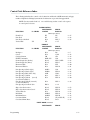
Configuration Printout . . . . . . . . . . . . . . . . . . . . . . . . . . . . . . . . . . . . . . . . . . . . . . . . . . . . . . . . . . . . . . . . 3-6
Hardware Jumper Configuration . . . . . . . . . . . . . . . . . . . . . . . . . . . . . . . . . . . . . . . . . . . . . . . . . . . . . . . . 3-8
P6000L/P6200L User's Reference Manual
i
Side Panel Removal - Floor Cabinet Model . . . . . . . . . . . . . . . . . . . . . . . . . . . . . . . . . . . . . . . . . . . . . 3-8
Chapter
3
Page
Configuration (continued)
Removing the PCBA - Floor Cabinet Model . . . . . . . . . . . . . . . . . . . . . . . . . . . . . . . . . . . . . . . . . . . . . 3-9
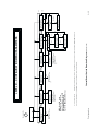
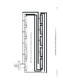
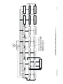
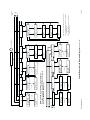
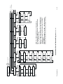
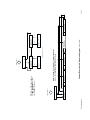
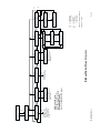
Control Panel Configuration Diagram . . . . . . . . . . . . . . . . . . . . . . . . . . . . . . . . . . . . . . . . . . . . . . . . . . . . 3-14
Level I - Print Format . . . . . . . . . . . . . . . . . . . . . . . . . . . . . . . . . . . . . . . . . . . . . . . . . . . . . . . . . . . . . . . . 3-14
Level II - Main Configuration Menus . . . . . . . . . . . . . . . . . . . . . . . . . . . . . . . . . . . . . . . . . . . . . . . . . . 3-14
Level III - Configuration Menu Parameters . . . . . . . . . . . . . . . . . . . . . . . . . . . . . . . . . . . . . . . . . . . . . 3-14
4
Graphics
Introduction . . . . . . . . . . . . . . . . . . . . . . . . . . . . . . . . . . . . . . . . . . . . . . . . . . . . . . . . . . . . . . . . . . . . . . . . . 4-1
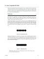
Serial Matrix Compatible Bit Image Graphics . . . . . . . . . . . . . . . . . . . . . . . . . . . . . . . . . . . . . . . . . . . . . 4-1
Plotting a Bit Image Pattern . . . . . . . . . . . . . . . . . . . . . . . . . . . . . . . . . . . . . . . . . . . . . . . . . . . . . . . . . . . 4-3
Bit Image Density . . . . . . . . . . . . . . . . . . . . . . . . . . . . . . . . . . . . . . . . . . . . . . . . . . . . . . . . . . . . . . . . . . . . 4-4
Bit Image Programming Format . . . . . . . . . . . . . . . . . . . . . . . . . . . . . . . . . . . . . . . . . . . . . . . . . . . . . . . . 4-5
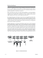
P-Series Compatible Plot Mode . . . . . . . . . . . . . . . . . . . . . . . . . . . . . . . . . . . . . . . . . . . . . . . . . . . . . . . . 4-7
Plot Density . . . . . . . . . . . . . . . . . . . . . . . . . . . . . . . . . . . . . . . . . . . . . . . . . . . . . . . . . . . . . . . . . . . . . . . . . 4-7
Plot Data Line Format . . . . . . . . . . . . . . . . . . . . . . . . . . . . . . . . . . . . . . . . . . . . . . . . . . . . . . . . . . . . . . . . 4-8
Plot Data Byte Format . . . . . . . . . . . . . . . . . . . . . . . . . . . . . . . . . . . . . . . . . . . . . . . . . . . . . . . . . . . . . . . . 4-9
Plotting the Data . . . . . . . . . . . . . . . . . . . . . . . . . . . . . . . . . . . . . . . . . . . . . . . . . . . . . . . . . . . . . . . . . . . . . 4-11
Combining Graphics and Text . . . . . . . . . . . . . . . . . . . . . . . . . . . . . . . . . . . . . . . . . . . . . . . . . . . . . . . . . . . 4-12
5
Vertical Format Units
Introduction . . . . . . . . . . . . . . . . . . . . . . . . . . . . . . . . . . . . . . . . . . . . . . . . . . . . . . . . . . . . . . . . . . . . . . . . . 5-1
DAVFU . . . . . . . . . . . . . . . . . . . . . . . . . . . . . . . . . . . . . . . . . . . . . . . . . . . . . . . . . . . . . . . . . . . . . . . . . . . . . 5-1
General DAVFU Programming . . . . . . . . . . . . . . . . . . . . . . . . . . . . . . . . . . . . . . . . . . . . . . . . . . . . . . . . 5-1
Start Load Code - 6E Hex . . . . . . . . . . . . . . . . . . . . . . . . . . . . . . . . . . . . . . . . . . . . . . . . . . . . . . . . . . . . 5-2
Channel Assignment . . . . . . . . . . . . . . . . . . . . . . . . . . . . . . . . . . . . . . . . . . . . . . . . . . . . . . . . . . . . . . . . . . 5-2
End Load Code - 6F Hex . . . . . . . . . . . . . . . . . . . . . . . . . . . . . . . . . . . . . . . . . . . . . . . . . . . . . . . . . . . . . 5-4
Using The DAVFU . . . . . . . . . . . . . . . . . . . . . . . . . . . . . . . . . . . . . . . . . . . . . . . . . . . . . . . . . . . . . . . . . . . 5-4
Clearing The DAVFU Memory . . . . . . . . . . . . . . . . . . . . . . . . . . . . . . . . . . . . . . . . . . . . . . . . . . . . . . . . . 5-4
DAVFU/IGP Execute Form Mode . . . . . . . . . . . . . . . . . . . . . . . . . . . . . . . . . . . . . . . . . . . . . . . . . . . . . . 5-5
DAVFU Line Slewing . . . . . . . . . . . . . . . . . . . . . . . . . . . . . . . . . . . . . . . . . . . . . . . . . . . . . . . . . . . . . . . . . 5-6
P-Series EVFU . . . . . . . . . . . . . . . . . . . . . . . . . . . . . . . . . . . . . . . . . . . . . . . . . . . . . . . . . . . . . . . . . . . . . . 5-7
General P-Series EVFU Programming Information . . . . . . . . . . . . . . . . . . . . . . . . . . . . . . . . . . . . . . 5-7
P-Series EVFU Command and Channel Codes . . . . . . . . . . . . . . . . . . . . . . . . . . . . . . . . . . . . . . . . . . 5-8
P-Series EVFU Form Definition Program . . . . . . . . . . . . . . . . . . . . . . . . . . . . . . . . . . . . . . . . . . . . . . . 5-10
Serial Emulation VFU . . . . . . . . . . . . . . . . . . . . . . . . . . . . . . . . . . . . . . . . . . . . . . . . . . . . . . . . . . . . . . . . . 5-14
Executing Vertical Tabs . . . . . . . . . . . . . . . . . . . . . . . . . . . . . . . . . . . . . . . . . . . . . . . . . . . . . . . . . . . . . . . 5-14
Vertical Tab Positions . . . . . . . . . . . . . . . . . . . . . . . . . . . . . . . . . . . . . . . . . . . . . . . . . . . . . . . . . . . . . . . . . 5-14
ii
P6000L/P6200L User's Reference Manual
Chapter
6
Page
Programming
Introduction . . . . . . . . . . . . . . . . . . . . . . . . . . . . . . . . . . . . . . . . . . . . . . . . . . . . . . . . . . . . . . . . . . . . . . . . . 6-1
Overstrike Mode . . . . . . . . . . . . . . . . . . . . . . . . . . . . . . . . . . . . . . . . . . . . . . . . . . . . . . . . . . . . . . . . . . . . . 6-1
Control Code Functions . . . . . . . . . . . . . . . . . . . . . . . . . . . . . . . . . . . . . . . . . . . . . . . . . . . . . . . . . . . . . . . 6-2
Special Function Code - Control Code Header . . . . . . . . . . . . . . . . . . . . . . . . . . . . . . . . . . . . . . . . . . . 6-2
Attribute Set and Reset Codes . . . . . . . . . . . . . . . . . . . . . . . . . . . . . . . . . . . . . . . . . . . . . . . . . . . . . . . . . . 6-2
Control Code Reference Index . . . . . . . . . . . . . . . . . . . . . . . . . . . . . . . . . . . . . . . . . . . . . . . . . . . . . . . . . . 6-3
Backspace . . . . . . . . . . . . . . . . . . . . . . . . . . . . . . . . . . . . . . . . . . . . . . . . . . . . . . . . . . . . . . . . . . . . . . . . . . . 6-5
Bell . . . . . . . . . . . . . . . . . . . . . . . . . . . . . . . . . . . . . . . . . . . . . . . . . . . . . . . . . . . . . . . . . . . . . . . . . . . . . . . . . 6-6
Bit Image Mode, Single Density . . . . . . . . . . . . . . . . . . . . . . . . . . . . . . . . . . . . . . . . . . . . . . . . . . . . . . . . . 6-7
Bit Image Mode, Double Density . . . . . . . . . . . . . . . . . . . . . . . . . . . . . . . . . . . . . . . . . . . . . . . . . . . . . . . . 6-8
Bit Image Mode, Double Density Double Speed . . . . . . . . . . . . . . . . . . . . . . . . . . . . . . . . . . . . . . . . . . . 6-9
Bit Image Mode, Quadruple Density . . . . . . . . . . . . . . . . . . . . . . . . . . . . . . . . . . . . . . . . . . . . . . . . . . . . . 6-10
Bold Print . . . . . . . . . . . . . . . . . . . . . . . . . . . . . . . . . . . . . . . . . . . . . . . . . . . . . . . . . . . . . . . . . . . . . . . . . . . 6-11
Bold Print Reset . . . . . . . . . . . . . . . . . . . . . . . . . . . . . . . . . . . . . . . . . . . . . . . . . . . . . . . . . . . . . . . . . . . . . . 6-12
Cancel . . . . . . . . . . . . . . . . . . . . . . . . . . . . . . . . . . . . . . . . . . . . . . . . . . . . . . . . . . . . . . . . . . . . . . . . . . . . . . 6-13
Carriage Return . . . . . . . . . . . . . . . . . . . . . . . . . . . . . . . . . . . . . . . . . . . . . . . . . . . . . . . . . . . . . . . . . . . . . . 6-14
Character Set Select (Control Codes) . . . . . . . . . . . . . . . . . . . . . . . . . . . . . . . . . . . . . . . . . . . . . . . . . . . . 6-15
Character Set Select (Printable Symbols) . . . . . . . . . . . . . . . . . . . . . . . . . . . . . . . . . . . . . . . . . . . . . . . . . 6-16
Condensed Print . . . . . . . . . . . . . . . . . . . . . . . . . . . . . . . . . . . . . . . . . . . . . . . . . . . . . . . . . . . . . . . . . . . . . . 6-17
Condensed Print Reset . . . . . . . . . . . . . . . . . . . . . . . . . . . . . . . . . . . . . . . . . . . . . . . . . . . . . . . . . . . . . . . . 6-18
Elongated (Double High) Print . . . . . . . . . . . . . . . . . . . . . . . . . . . . . . . . . . . . . . . . . . . . . . . . . . . . . . . . . 6-19
Emphasized Print . . . . . . . . . . . . . . . . . . . . . . . . . . . . . . . . . . . . . . . . . . . . . . . . . . . . . . . . . . . . . . . . . . . . . 6-20
Emphasized Print Reset . . . . . . . . . . . . . . . . . . . . . . . . . . . . . . . . . . . . . . . . . . . . . . . . . . . . . . . . . . . . . . . 6-21
EVFU Commands (P-Series) . . . . . . . . . . . . . . . . . . . . . . . . . . . . . . . . . . . . . . . . . . . . . . . . . . . . . . . . . . 6-22
Expanded (Double Wide) Print . . . . . . . . . . . . . . . . . . . . . . . . . . . . . . . . . . . . . . . . . . . . . . . . . . . . . . . . . 6-23
Expanded (Double Wide) Print (One Line Only) . . . . . . . . . . . . . . . . . . . . . . . . . . . . . . . . . . . . . . . . . . 6-24
Extended Character Set . . . . . . . . . . . . . . . . . . . . . . . . . . . . . . . . . . . . . . . . . . . . . . . . . . . . . . . . . . . . . . . . 6-25
Extended Character Set Cancel
(Primary Character Set Select) . . . . . . . . . . . . . . . . . . . . . . . . . . . . . . . . . . . . . . . . . . . . . . . . . . . . . . . . . . 6-26
Form Feed . . . . . . . . . . . . . . . . . . . . . . . . . . . . . . . . . . . . . . . . . . . . . . . . . . . . . . . . . . . . . . . . . . . . . . . . . . . 6-27
Forms Length Set (Inches) . . . . . . . . . . . . . . . . . . . . . . . . . . . . . . . . . . . . . . . . . . . . . . . . . . . . . . . . . . . . . 6-28
Forms Length Set (Lines) . . . . . . . . . . . . . . . . . . . . . . . . . . . . . . . . . . . . . . . . . . . . . . . . . . . . . . . . . . . . . . 6-29
Horizontal Tab . . . . . . . . . . . . . . . . . . . . . . . . . . . . . . . . . . . . . . . . . . . . . . . . . . . . . . . . . . . . . . . . . . . . . . . 6-30
Horizontal Tab Set . . . . . . . . . . . . . . . . . . . . . . . . . . . . . . . . . . . . . . . . . . . . . . . . . . . . . . . . . . . . . . . . . . . . 6-31
International Character Set Select . . . . . . . . . . . . . . . . . . . . . . . . . . . . . . . . . . . . . . . . . . . . . . . . . . . . . . . 6-32
Line Feed . . . . . . . . . . . . . . . . . . . . . . . . . . . . . . . . . . . . . . . . . . . . . . . . . . . . . . . . . . . . . . . . . . . . . . . . . . . 6-33
Line Feed n/216 Inch (one line only) . . . . . . . . . . . . . . . . . . . . . . . . . . . . . . . . . . . . . . . . . . . . . . . . . . . . . 6-34
Line Spacing 1/6 Inch . . . . . . . . . . . . . . . . . . . . . . . . . . . . . . . . . . . . . . . . . . . . . . . . . . . . . . . . . . . . . . . . . . 6-35
Line Spacing 1/8 Inch (8 lpi) . . . . . . . . . . . . . . . . . . . . . . . . . . . . . . . . . . . . . . . . . . . . . . . . . . . . . . . . . . . . 6-36
Line Spacing 8 lpi (One Line Only) . . . . . . . . . . . . . . . . . . . . . . . . . . . . . . . . . . . . . . . . . . . . . . . . . . . . . . 6-37
Line Spacing 7/72 Inch . . . . . . . . . . . . . . . . . . . . . . . . . . . . . . . . . . . . . . . . . . . . . . . . . . . . . . . . . . . . . . . . . 6-38
Line Spacing n/72 Inch (Asserted) . . . . . . . . . . . . . . . . . . . . . . . . . . . . . . . . . . . . . . . . . . . . . . . . . . . . . . . 6-39
Line Spacing n/72 Inch (Stored) . . . . . . . . . . . . . . . . . . . . . . . . . . . . . . . . . . . . . . . . . . . . . . . . . . . . . . . . . 6-40
P6000L/P6200L User's Reference Manual
iii
Chapter
6
Page
Programming (continued)
Line Spacing n/216 Inch . . . . . . . . . . . . . . . . . . . . . . . . . . . . . . . . . . . . . . . . . . . . . . . . . . . . . . . . . . . . . . . 6-41
Overscoring . . . . . . . . . . . . . . . . . . . . . . . . . . . . . . . . . . . . . . . . . . . . . . . . . . . . . . . . . . . . . . . . . . . . . . . . . . 6-42
Plot, Even Dot (P-Series High Density Graphics) . . . . . . . . . . . . . . . . . . . . . . . . . . . . . . . . . . . . . . . . . 6-43
Plot, Odd Dot (P-Series Normal Density Graphics) . . . . . . . . . . . . . . . . . . . . . . . . . . . . . . . . . . . . . . . 6-44
Printer Deselect . . . . . . . . . . . . . . . . . . . . . . . . . . . . . . . . . . . . . . . . . . . . . . . . . . . . . . . . . . . . . . . . . . . . . . 6-45
Printer Reset . . . . . . . . . . . . . . . . . . . . . . . . . . . . . . . . . . . . . . . . . . . . . . . . . . . . . . . . . . . . . . . . . . . . . . . . . 6-46
Printer Select . . . . . . . . . . . . . . . . . . . . . . . . . . . . . . . . . . . . . . . . . . . . . . . . . . . . . . . . . . . . . . . . . . . . . . . . 6-47
Print Mode/Pitch Selection . . . . . . . . . . . . . . . . . . . . . . . . . . . . . . . . . . . . . . . . . . . . . . . . . . . . . . . . . . . . . 6-48
RibbonMinder, Enable/Disable . . . . . . . . . . . . . . . . . . . . . . . . . . . . . . . . . . . . . . . . . . . . . . . . . . . . . . . . . 6-49
RibbonMinder, Set Job Rate . . . . . . . . . . . . . . . . . . . . . . . . . . . . . . . . . . . . . . . . . . . . . . . . . . . . . . . . . . . 6-50
RibbonMinder, When Worn Action . . . . . . . . . . . . . . . . . . . . . . . . . . . . . . . . . . . . . . . . . . . . . . . . . . . . . . 6-51
Skip-Over Perforation . . . . . . . . . . . . . . . . . . . . . . . . . . . . . . . . . . . . . . . . . . . . . . . . . . . . . . . . . . . . . . . . 6-52
Skip-Over Perforation Cancel . . . . . . . . . . . . . . . . . . . . . . . . . . . . . . . . . . . . . . . . . . . . . . . . . . . . . . . . . . 6-53
Superscript/Subscript Printing . . . . . . . . . . . . . . . . . . . . . . . . . . . . . . . . . . . . . . . . . . . . . . . . . . . . . . . . . . 6-54
Superscript/Subscript Printing Reset . . . . . . . . . . . . . . . . . . . . . . . . . . . . . . . . . . . . . . . . . . . . . . . . . . . . . 6-55
Underline . . . . . . . . . . . . . . . . . . . . . . . . . . . . . . . . . . . . . . . . . . . . . . . . . . . . . . . . . . . . . . . . . . . . . . . . . . . 6-56
Vertical Tab . . . . . . . . . . . . . . . . . . . . . . . . . . . . . . . . . . . . . . . . . . . . . . . . . . . . . . . . . . . . . . . . . . . . . . . . . . 6-57
Vertical Tab Set (Serial Matrix) . . . . . . . . . . . . . . . . . . . . . . . . . . . . . . . . . . . . . . . . . . . . . . . . . . . . . . . . . 6-58
7
Interfaces
Introduction . . . . . . . . . . . . . . . . . . . . . . . . . . . . . . . . . . . . . . . . . . . . . . . . . . . . . . . . . . . . . . . . . . . . . . . . . 7-1
Dataproducts Parallel Interface . . . . . . . . . . . . . . . . . . . . . . . . . . . . . . . . . . . . . . . . . . . . . . . . . . . . . . . . . 7-1
Dataproducts Interface Signals . . . . . . . . . . . . . . . . . . . . . . . . . . . . . . . . . . . . . . . . . . . . . . . . . . . . . . . . . 7-1
Parallel Interface Configuration . . . . . . . . . . . . . . . . . . . . . . . . . . . . . . . . . . . . . . . . . . . . . . . . . . . . . . . . 7-3
Centronics Parallel Interface . . . . . . . . . . . . . . . . . . . . . . . . . . . . . . . . . . . . . . . . . . . . . . . . . . . . . . . . . . . 7-3
Centronics Interface Signals . . . . . . . . . . . . . . . . . . . . . . . . . . . . . . . . . . . . . . . . . . . . . . . . . . . . . . . . . . . 7-3
Parallel Interface Configuration . . . . . . . . . . . . . . . . . . . . . . . . . . . . . . . . . . . . . . . . . . . . . . . . . . . . . . . . 7-4
RS-232 Serial Interface . . . . . . . . . . . . . . . . . . . . . . . . . . . . . . . . . . . . . . . . . . . . . . . . . . . . . . . . . . . . . . . 7-5
RS-232 Interface Signals . . . . . . . . . . . . . . . . . . . . . . . . . . . . . . . . . . . . . . . . . . . . . . . . . . . . . . . . . . . . . 7-5
Serial Interface Protocols . . . . . . . . . . . . . . . . . . . . . . . . . . . . . . . . . . . . . . . . . . . . . . . . . . . . . . . . . . . . . . 7-6
Serial Interface Configuration . . . . . . . . . . . . . . . . . . . . . . . . . . . . . . . . . . . . . . . . . . . . . . . . . . . . . . . . . . 7-7
Alternate Terminating Resistors . . . . . . . . . . . . . . . . . . . . . . . . . . . . . . . . . . . . . . . . . . . . . . . . . . . . . . . . . 7-8
Floor Cabinet Model . . . . . . . . . . . . . . . . . . . . . . . . . . . . . . . . . . . . . . . . . . . . . . . . . . . . . . . . . . . . . . . . . 7-8
Pedestal Model . . . . . . . . . . . . . . . . . . . . . . . . . . . . . . . . . . . . . . . . . . . . . . . . . . . . . . . . . . . . . . . . . . . . . . 7-10
Interface Jumper Platform . . . . . . . . . . . . . . . . . . . . . . . . . . . . . . . . . . . . . . . . . . . . . . . . . . . . . . . . . . . . . 7-12
8
Maintenance
Introduction . . . . . . . . . . . . . . . . . . . . . . . . . . . . . . . . . . . . . . . . . . . . . . . . . . . . . . . . . . . . . . . . . . . . . . . . . 8-1
General Cleaning . . . . . . . . . . . . . . . . . . . . . . . . . . . . . . . . . . . . . . . . . . . . . . . . . . . . . . . . . . . . . . . . . . . . . 8-1
Exterior Cleaning . . . . . . . . . . . . . . . . . . . . . . . . . . . . . . . . . . . . . . . . . . . . . . . . . . . . . . . . . . . . . . . . . . . . 8-1
Interior Cleaning . . . . . . . . . . . . . . . . . . . . . . . . . . . . . . . . . . . . . . . . . . . . . . . . . . . . . . . . . . . . . . . . . . . . 8-1
iv
P6000L/P6200L User's Reference Manual
Chapter
8
Page
Maintenance (continued)
Cleaning the Paper Motion Detector . . . . . . . . . . . . . . . . . . . . . . . . . . . . . . . . . . . . . . . . . . . . . . . . . . . . 8-3
Printer Self-Tests . . . . . . . . . . . . . . . . . . . . . . . . . . . . . . . . . . . . . . . . . . . . . . . . . . . . . . . . . . . . . . . . . . . . 8-4
Running the Self-Tests . . . . . . . . . . . . . . . . . . . . . . . . . . . . . . . . . . . . . . . . . . . . . . . . . . . . . . . . . . . . . . . 8-4
Hex Code Printout . . . . . . . . . . . . . . . . . . . . . . . . . . . . . . . . . . . . . . . . . . . . . . . . . . . . . . . . . . . . . . . . . . . . 8-5
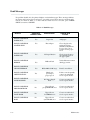
Fault Messages . . . . . . . . . . . . . . . . . . . . . . . . . . . . . . . . . . . . . . . . . . . . . . . . . . . . . . . . . . . . . . . . . . . . . . . 8-6
9
RibbonMinder
Introduction . . . . . . . . . . . . . . . . . . . . . . . . . . . . . . . . . . . . . . . . . . . . . . . . . . . . . . . . . . . . . . . . . . . . . . . . . 9-1
Overview . . . . . . . . . . . . . . . . . . . . . . . . . . . . . . . . . . . . . . . . . . . . . . . . . . . . . . . . . . . . . . . . . . . . . . . . . . . . 9-1
Analyzing a Job . . . . . . . . . . . . . . . . . . . . . . . . . . . . . . . . . . . . . . . . . . . . . . . . . . . . . . . . . . . . . . . . . . . . . . 9-3
Running a Job . . . . . . . . . . . . . . . . . . . . . . . . . . . . . . . . . . . . . . . . . . . . . . . . . . . . . . . . . . . . . . . . . . . . . . . . 9-6
Multiple Jobs on the Same Ribbon . . . . . . . . . . . . . . . . . . . . . . . . . . . . . . . . . . . . . . . . . . . . . . . . . . . . . . 9-9
Changing a Ribbon Early . . . . . . . . . . . . . . . . . . . . . . . . . . . . . . . . . . . . . . . . . . . . . . . . . . . . . . . . . . . . . . 9-10
Host Interface . . . . . . . . . . . . . . . . . . . . . . . . . . . . . . . . . . . . . . . . . . . . . . . . . . . . . . . . . . . . . . . . . . . . . . . . 9-11
Application Hints . . . . . . . . . . . . . . . . . . . . . . . . . . . . . . . . . . . . . . . . . . . . . . . . . . . . . . . . . . . . . . . . . . . . . 9-12
10
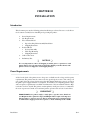
Installation
Introduction . . . . . . . . . . . . . . . . . . . . . . . . . . . . . . . . . . . . . . . . . . . . . . . . . . . . . . . . . . . . . . . . . . . . . . . . . 10-1
Power Requirements . . . . . . . . . . . . . . . . . . . . . . . . . . . . . . . . . . . . . . . . . . . . . . . . . . . . . . . . . . . . . . . . . . 10-1
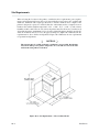
Site Requirements . . . . . . . . . . . . . . . . . . . . . . . . . . . . . . . . . . . . . . . . . . . . . . . . . . . . . . . . . . . . . . . . . . . . 10-2
Floor Cabinet Model Installation . . . . . . . . . . . . . . . . . . . . . . . . . . . . . . . . . . . . . . . . . . . . . . . . . . . . . . . . 10-3
Paper Stacking Chain Assembly Installation . . . . . . . . . . . . . . . . . . . . . . . . . . . . . . . . . . . . . . . . . . . . . . 10-3
Shipping Restraints Removal . . . . . . . . . . . . . . . . . . . . . . . . . . . . . . . . . . . . . . . . . . . . . . . . . . . . . . . . . . 10-4
Platen Restraints Removal . . . . . . . . . . . . . . . . . . . . . . . . . . . . . . . . . . . . . . . . . . . . . . . . . . . . . . . . . . . . . 10-6
Front Shock Mount Restraint Screw Removal . . . . . . . . . . . . . . . . . . . . . . . . . . . . . . . . . . . . . . . . . . . . 10-6
Side Shock Mount Restraint Screw Removal . . . . . . . . . . . . . . . . . . . . . . . . . . . . . . . . . . . . . . . . . . . . . 10-7
Pedestal Model Installation . . . . . . . . . . . . . . . . . . . . . . . . . . . . . . . . . . . . . . . . . . . . . . . . . . . . . . . . . . . . . 10-11
Pedestal Assembly . . . . . . . . . . . . . . . . . . . . . . . . . . . . . . . . . . . . . . . . . . . . . . . . . . . . . . . . . . . . . . . . . . . 10-11
Table Top Mounting . . . . . . . . . . . . . . . . . . . . . . . . . . . . . . . . . . . . . . . . . . . . . . . . . . . . . . . . . . . . . . . . . . 10-14
Shipping Restraint Removal - Pedestal Model . . . . . . . . . . . . . . . . . . . . . . . . . . . . . . . . . . . . . . . . . . . 10-15
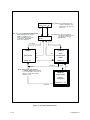
Cable Connections . . . . . . . . . . . . . . . . . . . . . . . . . . . . . . . . . . . . . . . . . . . . . . . . . . . . . . . . . . . . . . . . . . . . 10-17
Preliminary Test . . . . . . . . . . . . . . . . . . . . . . . . . . . . . . . . . . . . . . . . . . . . . . . . . . . . . . . . . . . . . . . . . . . . . . 10-19
Appendix A
Standard ASCII Character Set and Equivalents . . . . . . . . . . . . . . . . . . . . . . . . . . . . . . . . . . . . . . . . . . . . A-1
Appendix B
Serial Emulation Mode Character Set #1 . . . . . . . . . . . . . . . . . . . . . . . . . . . . . . . . . . . . . . . . . . . . . . . . . B-1
Serial Emulation Mode Character Set #2 . . . . . . . . . . . . . . . . . . . . . . . . . . . . . . . . . . . . . . . . . . . . . . . . . B-2
P6000L/P6200L User's Reference Manual
v
Chapter
Page
Appendix B (continued)
P-Series Mode Character Set #1 . . . . . . . . . . . . . . . . . . . . . . . . . . . . . . . . . . . . . . . . . . . . . . . . . . . . . . . B-3
P-Series Mode Character Set #2 . . . . . . . . . . . . . . . . . . . . . . . . . . . . . . . . . . . . . . . . . . . . . . . . . . . . . . . B-4
International Characters . . . . . . . . . . . . . . . . . . . . . . . . . . . . . . . . . . . . . . . . . . . . . . . . . . . . . . . . . . . . . . . B-5
Appendix C
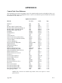
Specifications . . . . . . . . . . . . . . . . . . . . . . . . . . . . . . . . . . . . . . . . . . . . . . . . . . . . . . . . . . . . . . . . . . . . . . . . C-1
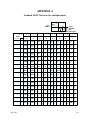
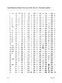
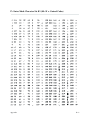
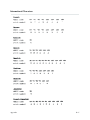
Appendix D
Control Code Cross Reference . . . . . . . . . . . . . . . . . . . . . . . . . . . . . . . . . . . . . . . . . . . . . . . . . . . . . . . . . . D-1
vi
P6000L/P6200L User's Reference Manual
LIST OF FIGURES
Figure
Page
1-1
Typical Character Formation . . . . . . . . . . . . . . . . . . . . . . . . . . . . . . . . . . . . . . . . . . . . . . . . . . . . 1-3
1-2
Dot Matrix Line Printing . . . . . . . . . . . . . . . . . . . . . . . . . . . . . . . . . . . . . . . . . . . . . . . . . . . . . . . 1-4
2-1
Power Switch - Floor Cabinet Model . . . . . . . . . . . . . . . . . . . . . . . . . . . . . . . . . . . . . . . . . . . . . 2-3
2-2
Power Switch - Pedestal Model . . . . . . . . . . . . . . . . . . . . . . . . . . . . . . . . . . . . . . . . . . . . . . . . . 2-3
2-3
Control Panel . . . . . . . . . . . . . . . . . . . . . . . . . . . . . . . . . . . . . . . . . . . . . . . . . . . . . . . . . . . . . . . . . 2-5
2-4
Paper Adjustment Controls - Floor Cabinet Model . . . . . . . . . . . . . . . . . . . . . . . . . . . . . . . . . 2-8
2-5
Paper Adjustment Controls - Pedestal Model . . . . . . . . . . . . . . . . . . . . . . . . . . . . . . . . . . . . . 2-9
2-6
Forms Thickness Adjustment Lever . . . . . . . . . . . . . . . . . . . . . . . . . . . . . . . . . . . . . . . . . . . . . . 2-10
2-7
Vertical Position Knob . . . . . . . . . . . . . . . . . . . . . . . . . . . . . . . . . . . . . . . . . . . . . . . . . . . . . . . . . 2-10
2-8
Horizontal Adjustment Knob . . . . . . . . . . . . . . . . . . . . . . . . . . . . . . . . . . . . . . . . . . . . . . . . . . . . 2-11
2-9
Left Paper Tractor . . . . . . . . . . . . . . . . . . . . . . . . . . . . . . . . . . . . . . . . . . . . . . . . . . . . . . . . . . . . . 2-12
2-10
Loading Paper . . . . . . . . . . . . . . . . . . . . . . . . . . . . . . . . . . . . . . . . . . . . . . . . . . . . . . . . . . . . . . . . 2-14
2-11
Setting Top-Of-Form . . . . . . . . . . . . . . . . . . . . . . . . . . . . . . . . . . . . . . . . . . . . . . . . . . . . . . . . . 2-15
2-12
Front Paper Fence Installation - Floor Cabinet Models . . . . . . . . . . . . . . . . . . . . . . . . . . . . . 2-16
2-13
Rear Paper Fence Installation - Floor Cabinet Models . . . . . . . . . . . . . . . . . . . . . . . . . . . . . . 2-17
2-14
Paper Tent Installation - Floor Cabinet Models . . . . . . . . . . . . . . . . . . . . . . . . . . . . . . . . . . . . 2-18
2-15
Paper Stacking - Floor Cabinet Models . . . . . . . . . . . . . . . . . . . . . . . . . . . . . . . . . . . . . . . . . . . 2-18
2-16
Ribbon Replacement . . . . . . . . . . . . . . . . . . . . . . . . . . . . . . . . . . . . . . . . . . . . . . . . . . . . . . . . . . . 2-21
3-1
Sample Configuration Printout . . . . . . . . . . . . . . . . . . . . . . . . . . . . . . . . . . . . . . . . . . . . . . . . . . 3-7
3-2
Side Panel Removal - Floor Cabinet Model . . . . . . . . . . . . . . . . . . . . . . . . . . . . . . . . . . . . . . . 3-9
3-3
PCBA Removal - Floor Cabinet Model Printer . . . . . . . . . . . . . . . . . . . . . . . . . . . . . . . . . . . . 3-10
3-4
PCBA Removal - Pedestal Model Printer . . . . . . . . . . . . . . . . . . . . . . . . . . . . . . . . . . . . . . . . . 3-12
3-5
Control Panel Configuration Diagram Symbols . . . . . . . . . . . . . . . . . . . . . . . . . . . . . . . . . . . . . 3-15
3-6
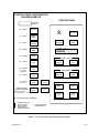
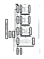
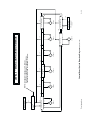
Control Panel Overview . . . . . . . . . . . . . . . . . . . . . . . . . . . . . . . . . . . . . . . . . . . . . . . . . . . . . . . . 3-16
4-1
Binary Data Byte . . . . . . . . . . . . . . . . . . . . . . . . . . . . . . . . . . . . . . . . . . . . . . . . . . . . . . . . . . . . . . 4-1
4-2
Vertical Data Byte Pattern . . . . . . . . . . . . . . . . . . . . . . . . . . . . . . . . . . . . . . . . . . . . . . . . . . . . . . 4-2
4-3
Bit Image Pattern from an ASCII Character . . . . . . . . . . . . . . . . . . . . . . . . . . . . . . . . . . . . . . . 4-2
4-4
Bit Image Pattern Plan . . . . . . . . . . . . . . . . . . . . . . . . . . . . . . . . . . . . . . . . . . . . . . . . . . . . . . . . . 4-3
4-5
Sample Single Density Bit Image Graphics . . . . . . . . . . . . . . . . . . . . . . . . . . . . . . . . . . . . . . . . . 4-6
4-6
Normal Density Plot . . . . . . . . . . . . . . . . . . . . . . . . . . . . . . . . . . . . . . . . . . . . . . . . . . . . . . . . . . . 4-7
4-7
High Density Plot . . . . . . . . . . . . . . . . . . . . . . . . . . . . . . . . . . . . . . . . . . . . . . . . . . . . . . . . . . . . . . 4-7
4-8
Plot Data Line Format . . . . . . . . . . . . . . . . . . . . . . . . . . . . . . . . . . . . . . . . . . . . . . . . . . . . . . . . . 4-8
4-9
P-Series Plot Data Byte Format . . . . . . . . . . . . . . . . . . . . . . . . . . . . . . . . . . . . . . . . . . . . . . . . . 4-9
P6000L/P6200L User's Reference Manual
vii
Figure
Page
4-10
Odd Dot Plot Pattern Plan . . . . . . . . . . . . . . . . . . . . . . . . . . . . . . . . . . . . . . . . . . . . . . . . . . . . . . 4-11
4-11
Sample Odd Dot Plot . . . . . . . . . . . . . . . . . . . . . . . . . . . . . . . . . . . . . . . . . . . . . . . . . . . . . . . . . . 4-12
4-12
Truncated Character Line . . . . . . . . . . . . . . . . . . . . . . . . . . . . . . . . . . . . . . . . . . . . . . . . . . . . . . . 4-12
5-1
Sample DAVFU Form Design . . . . . . . . . . . . . . . . . . . . . . . . . . . . . . . . . . . . . . . . . . . . . . . . . . . 5-2
5-2
Sample P-Series EVFU Form Definition Program . . . . . . . . . . . . . . . . . . . . . . . . . . . . . . . . . 5-10
5-3
Sample Serial Matrix Vertical Tab Positions . . . . . . . . . . . . . . . . . . . . . . . . . . . . . . . . . . . . . . . . 5-15
6-1
Overstrike/Underlining Example . . . . . . . . . . . . . . . . . . . . . . . . . . . . . . . . . . . . . . . . . . . . . . . . . 6-1
7-1
Alternate Terminating Resistor Location - Floor Cabinet Model . . . . . . . . . . . . . . . . . . . . . 7-9
7-2
Alternate Terminating Resistor Location - Pedestal Model . . . . . . . . . . . . . . . . . . . . . . . . . . 7-11
7-3
Interface Jumper Platform Orientation . . . . . . . . . . . . . . . . . . . . . . . . . . . . . . . . . . . . . . . . . . . 7-12
8-1
Interior Cleaning . . . . . . . . . . . . . . . . . . . . . . . . . . . . . . . . . . . . . . . . . . . . . . . . . . . . . . . . . . . . . . 8-2
8-2
Cleaning the Paper Motion Detector . . . . . . . . . . . . . . . . . . . . . . . . . . . . . . . . . . . . . . . . . . . . . 8-3
10-1
Site Requirements - Floor Cabinet Model . . . . . . . . . . . . . . . . . . . . . . . . . . . . . . . . . . . . . . . . 10-2
10-2
Site Requirements - Pedestal Model . . . . . . . . . . . . . . . . . . . . . . . . . . . . . . . . . . . . . . . . . . . . . 10-3
10-3
Chain Assembly Installation - Floor Cabinet Model . . . . . . . . . . . . . . . . . . . . . . . . . . . . . . . . 10-4
10-4
Shipping Restraint Locations - Floor Cabinet Model . . . . . . . . . . . . . . . . . . . . . . . . . . . . . . . 10-5
10-5
Platen Restraint Removal - Floor Cabinet Model . . . . . . . . . . . . . . . . . . . . . . . . . . . . . . . . . . 10-6
10-6
Front Shock Mount Restraint Screw Removal - Floor Cabinet Model . . . . . . . . . . . . . . . . . 10-7
10-7
Side Panel Removal - Floor Cabinet Model . . . . . . . . . . . . . . . . . . . . . . . . . . . . . . . . . . . . . . . 10-8
10-8
Lowering the Card Cage - Floor Cabinet Model . . . . . . . . . . . . . . . . . . . . . . . . . . . . . . . . . . . 10-8
10-9
Side Shock Mount Restraint Screw Removal - Floor Cabinet Model . . . . . . . . . . . . . . . . . . 10-10
10-10 Pedestal Legs Installation - Pedestal Model . . . . . . . . . . . . . . . . . . . . . . . . . . . . . . . . . . . . . . . 10-12
10-11 Rubber Feet Removal - Pedestal Model . . . . . . . . . . . . . . . . . . . . . . . . . . . . . . . . . . . . . . . . . . 10-13
10-12 Pedestal Mounting - Pedestal Model . . . . . . . . . . . . . . . . . . . . . . . . . . . . . . . . . . . . . . . . . . . . 10-13
10-13 Table Top Mounting Specifications - Pedestal Model . . . . . . . . . . . . . . . . . . . . . . . . . . . . . . . 10-14
10-14 Shipping Restraint Removal - Pedestal Model . . . . . . . . . . . . . . . . . . . . . . . . . . . . . . . . . . . . . 10-16
10-15 Cable Connections - Floor Cabinet Model . . . . . . . . . . . . . . . . . . . . . . . . . . . . . . . . . . . . . . . . 10-17
10-16 Cable Connections - Pedestal Model . . . . . . . . . . . . . . . . . . . . . . . . . . . . . . . . . . . . . . . . . . . . . 10-18
viii
P6000L/P6200L User's Reference Manual
LIST OF TABLES
Table
Page
1-1
Print Rate . . . . . . . . . . . . . . . . . . . . . . . . . . . . . . . . . . . . . . . . . . . . . . . . . . . . . . . . . . . . . . . . . . . . 1-5
1-2
Plot Rate . . . . . . . . . . . . . . . . . . . . . . . . . . . . . . . . . . . . . . . . . . . . . . . . . . . . . . . . . . . . . . . . . . . . . 1-5
3-1
Printronix Default Configuration Values . . . . . . . . . . . . . . . . . . . . . . . . . . . . . . . . . . . . . . . . . . 3-5
3-2
Hardware Jumper Configuration . . . . . . . . . . . . . . . . . . . . . . . . . . . . . . . . . . . . . . . . . . . . . . . . . 3-13
4-1
Example Bit Image Pattern Decimal Values . . . . . . . . . . . . . . . . . . . . . . . . . . . . . . . . . . . . . . . . 4-4
4-2
Plot Data Byte Dot Patterns . . . . . . . . . . . . . . . . . . . . . . . . . . . . . . . . . . . . . . . . . . . . . . . . . . . . . 4-10
5-1
DAVFU Channel Assignment . . . . . . . . . . . . . . . . . . . . . . . . . . . . . . . . . . . . . . . . . . . . . . . . . . . 5-3
5-3
DAVFU Channel Instruction . . . . . . . . . . . . . . . . . . . . . . . . . . . . . . . . . . . . . . . . . . . . . . . . . . . . 5-5
5-5
P-Series EVFU Codes - PI Line Enabled . . . . . . . . . . . . . . . . . . . . . . . . . . . . . . . . . . . . . . . . 5-9
5-7
Example P-Series EVFU Channel Functions . . . . . . . . . . . . . . . . . . . . . . . . . . . . . . . . . . . . . . 5-12
6-1
Character Pitches Available by Print Mode . . . . . . . . . . . . . . . . . . . . . . . . . . . . . . . . . . . . . . . . 6-48
7-1
Connector Pin Assignments for Dataproducts Interface with AMP Connector . . . . . . . . . . . 7-2
7-2
Centronics Interface Connector Pin Assignments . . . . . . . . . . . . . . . . . . . . . . . . . . . . . . . . . . . 7-4
7-3
Serial Interface Pin Assignments . . . . . . . . . . . . . . . . . . . . . . . . . . . . . . . . . . . . . . . . . . . . . . . . . 7-6
7-4
Interface Jumper Configuration . . . . . . . . . . . . . . . . . . . . . . . . . . . . . . . . . . . . . . . . . . . . . . . . . . 7-12
8-1
Fault Messages . . . . . . . . . . . . . . . . . . . . . . . . . . . . . . . . . . . . . . . . . . . . . . . . . . . . . . . . . . . . . . . . 8-6
P6000L/P6200L User's Reference Manual
ix
ABOUT THIS MANUAL
This manual has been written and formatted in a way to make it easy for you to use. The followĆ
ing is some general information about this User's Reference Manual.
What This Manual Contains
This manual is divided into chapters that contain all the information required to use the
printer. Chapters provide introductory information, complete operating information, graphics
data, Vertical Format Unit data, programming information, maintenance procedures, interĆ
face descriptions, and appendices of supplemental information.
This manual is written for the advanced level systems engineer or experienced programmer
who will interface this printer with the host computer or who will prepare software for host
computer use to drive the printer. Background information covering fundamental programĆ
ming concepts is not provided in this documentation.
Warnings, Cautions, and Notes
Additional information requiring special attention is provided under the headings WARNING,
CAUTION, IMPORTANT, and NOTE. WARNINGs provide information about conditions
that could lead to injury; CAUTIONs provide information about conditions that could damage
the printer; IMPORTANT provides information that should be stressed. NOTEs, printed in
italics, provide supplemental information that could affect printer operation or use.
Switches and Indicators
Throughout this manual, switches, indicators, and possible switch settings or positions are
printed in UPPERCASE TYPE. This allows you to easily identify within the text items that are
located on the printer.
x
P6000L/P6200L User's Reference Manual
CHAPTER 1
OVERVIEW
Introduction
The information in this manual applies to both P6000L and P6200L Series printers. The
P6000L Series is the pedestal model printer and the P6200L is the floor cabinet model printer.
The P6040L and the P6240L are 400 line per minute printers; the P6080L and P6280L are 800
line per minute printers. All models will be identified throughout as P6000L/P6200L Series or
simply the printer, unless specifically noted otherwise.
The Printronix P6000L/P6200L Series printers are quiet, full-featured, multifunction line
printers. Along with the basic P-Series functions, the P6000L/P6200L include CorresponĆ
dence quality print for Near Letter Quality (NLQ) printing requirements, high speed printing,
and character-by-character attributes (Dynamic Character Generation) for wider applicaĆ
tion compatibility.
This chapter presents an overview of the printer:
n
Features
n
Optional Features
n
Character Formation
n
Dot Matrix Line Printing
n
Print Rate
n
Plot Rate
Refer to the Installation chapter for information on power and site requirements, and printer
installation.
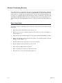
Features
P6000L/P6200L Series printers provide the following standard features:
n
Quiet Operation
D
Overview
The floor cabinet models feature extra quiet operation
n
P-Series and Serial Matrix (IBMr Graphic Printer) emulation protocols
n
P-Series Plot and Bit Image Graphics
n
Dynamic Character Generation
D
Selectable pitch
D
Elongated print
D
Shadow print
D
Expanded print
1-1
D
Automatic underline
D
Automatic overscore
D
Superscript printing
D
Subscript printing
n
Selectable Forms Length
n
Electronic Vertical Formatting
D
Standard Printronix electronic vertical format unit (EVFU)
D
12 channel direct access vertical format unit (DAVFU)
n
Resident International Character Sets
n
RibbonMinderT ribbon life monitor
n
Built-in Self-Test and Diagnostics
n
Configuration Printout
n
Data Stream Hex Code Printout
n
Resident Serial and Parallel Interfaces
Two separate graphics capabilities have been included in the printer: standard P-Series oddeven dot Plot Mode graphics and Bit Image graphics standard on Printronix MVP, P3000, and
P9000 Series printers and many other serial matrix printers. Intelligent graphics capabilities
are available by using the Printronix IGP-10 option.
Serial matrix compatibility makes the printer emulate the most common style of printer for
personal computers, but at much higher speeds. The user may select industry standard
Printronix P-Series or Serial Matrix compatibility from the control panel.
The programmable Vertical Format Unit provides rapid paper advance to specified lines for
printing repetitive and continuous forms. When P-Series compatible protocol is used, either
the P-Series compatible EVFU (Electronic Vertical Format Unit) or Dataproducts compatĆ
ible DAVFU (Direct Access Vertical Format Unit) may be selected. In the Serial Matrix protoĆ
col, an 8 channel serial vertical format unit is available.
Optional Features
P6000L/P6200L Series printer capabilities and versatility can be enhanced by the following opĆ
tions. For more information, contact an authorized Printronix representative.
1-2
n
Intelligent Graphics Processor (IGPT) - Allows the user to create and store forms,
generate logos, bar codes, expanded characters, and other graphics. Forms can be
created with a variety of graphic components and overlayed with alphanumeric and
bar code data in a single pass. The IGP may be ordered with either Printronix graphic
commands or QMSR protocol compatibility. Available as a field installable option.
n
IBM Interfaces - Includes PI-5225 (Twinax) and PI-3287 (Coax) protocol conĆ
verters to provide compatibility to IBM mainframe and mid-range computers.
Available as a field installable option.
n
Character Set Options - Accommodates various printable symbol or special characĆ
ter set requirements with field installable and changed socket mounted PROMs. All
the standard Printronix character sets for the P-Series printers are available for the
printer. Additionally, custom character sets can be ordered.
Overview
n
240 vac Conversion Kit - Changes the printer power source requirement from 120
vac to 240 vac. Available as a field installable option.
n
Quick Access Configuration - This optional cabinet and down tractors for pedestal
model printers allows easy access to labels and forms without lifting the front cover.
n
Pedestal - A stand designed for the printer. The pedestal includes locking casters,
bottom feed paper path and accepts the optional paper stacker. Available as a field
installable option.
n
Quietized Enclosed Pedestal - A stand for the pedestal models with an enclosure for
supply paper and reduced acoustical rating. Includes locking casters, bottom feed
paper path, and accepts optional paper stacker. Available as a field installable opĆ
tion.
n
Paper Stacker - is provided for use with the pedestal model printers. Collects and
properly stacks the printed output. Can be used with the optional pedestal and acts
as a caddy to transport the paper. Available as a field installable option.
Character Formation
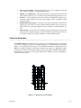
The P6000L/P6200L Series printers generate characters by assembling groups of dots in matriĆ
ces. Dots are overlapped to produce a solid appearing character of uniform density as shown in
Figure 1-1. Dot impressions are made by a row of hammers installed on a moving shuttle. The
400 lines per minute models have 44 hammers mounted on the shuttle; the 800 lines per minute
models have 66 hammers. The hammers impact the paper through a moving ink ribbon. HoriĆ
zontal shuttle movement and vertical paper advancement combine for precise dot printing to
form the character matrix.
Figure 1-1. Typical Character Formation
Overview
1-3
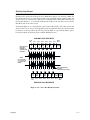
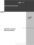
Dot Matrix Line Printing
Unlike single head dot matrix printing, the Printronix P6000L/P6200L Series creates graphics
and characters by printing an entire dot row at one time. As shown in Figure 1-2, dots are
printed in both directions of shuttle travel. In the 400 line per minute printers, the shuttle
sweeps through three tenths (3/10) of an inch. In the 800 line per minute printers, the shuttle
sweeps through two tenths (2/10) of an inch. Paper is advanced as the shuttle reverses direction
and the next row of dots is printed.
During each sweep of the shuttle, hammers are activated to print dots at selected positions in a
single dot row. When the shuttle reaches the end of a sweep, it reverses direction, paper adĆ
vances one dot row, and the hammers print the next row of dots.
After an entire line of characters is printed, hammer activity ceases and the paper advances to
the first dot row of the next print line. This creates a series of blank rows between lines of charĆ
acters. The number of rows allowed for line separation depends on the line spacing selected.
Line spacing may be selected from the control panel or the host computer.
INDICATES DIRECTION OF SHUTTLE MOVEMENT
DOT
ROW
ONE
CHARACTER
ROW
*
**
START
1
2
3
4
5
6
7
8*
9 **
10
11
0
12
1
2
PAPER
ADVANCES
PAPER
FEED
SPACE
PAPER
ADVANCES
USED FOR LOWERCASE DESCENDER ONLY
USED FOR UNDERLINE AND LOWERCASE DESCENDER
NOTE: 400 lpm models sweep through three character positions
800 lpm models sweep through two character positions
Figure 1-2. Dot Matrix Line Printing
1-4
Overview
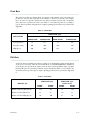
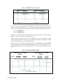
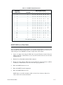
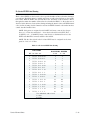
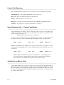
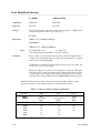
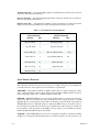
Print Rate
The print rate, in lines per minute (lpm), is a function of the number of dot rows required to
produce the character line regardless of the number of characters in the line. For example,
more dot rows are required to print lowercase characters with descenders and consequently,
those characters are printed at a slower rate. Table 1-1 describes the print rate according to
type of character printed and print mode. Complete printing specifications are provided in the
Appendix.
Table 1-1. Print Rate
PRINT RATE (lpm)
PRINT MODE
UPPERCASE ONLY
P6040L/P6240L
P6080L/P6280L
UPPER/LOWERCASE
P6040L/P6240L
P6080L/P6280L
Correspondence
ă89
177
ă77
154
Data Processing
300
600
240
480
High Speed
400
800
342
685
Plot Rate
As well as character printing, the printer is capable of dot addressable graphic plotting. Based
on the protocol selected, either P-Series Plot Mode or Serial Matrix Bit Image Graphics is
used; the plot rate specifications apply to both P-Series and Serial Matrix types of graphic
plotting. The plot rate (in inches per minute, ipm) is described in Table 1-2 according to the
dot density (in dots per inch, dpi). Complete plotting specifications are provided in Appendix
C.
Table 1-2. Plot Rate
PLOT RATE (ipm)
DENSITY (dpi)
P6040L/
P6240L
P6080L/
P6280L
PLOT RATE (ipm)
Unidirectional
P6040L/
P6080L/
P6240L
P6280L
60 Horz x 144 Vert (NLQ mode)
16.8
33.6
8.4
16.8
60 Horz x 72 Vert (DP mode)
33
66
16.6
33
60 Horz x 48 Vert (High Speed)
50
100
25
50
Overview
1-5
1-6
Overview
CHAPTER 2
OPERATION
Introduction
This chapter describes basic P6000L/P6200L Series controls and operating procedures. OperaĆ
tion information and cleaning practices are also provided in the Operator's Guide. Refer to the
Installation chapter for information on power and site requirements, and printer installation.
P6000L/P6200L Series printers function either online or offline. When online, the printer is
capable of receiving data and control commands from the host computer. The message display
indicates the printer is online and the current print mode. When offline, communication is susĆ
pended between the printer and the host computer and the message OFFLINE READY apĆ
pears on the display. Set the printer offline to perform the following tasks:
n
Select Configuration Values
n
Configure the Printer
n
Run the Self-Test
n
Set Top-of-Form
n
Perform a Hex Dump
n
Set Line Spacing
n
Load Paper and Ribbon
n
Advance Forms
n
Change Print Modes
n
Adjust Paper Tractors
n
Advance Paper
n
Cleaning/Routine Maintenance
P6000L/P6200L Series printers respond to two different command sets or protocol modes:
n
P-Series emulation mode
n
Serial Matrix emulation mode
The selected protocol determines which programming standard is used by the host computer to
communicate with the printer. Either protocol can be selected as required by the application.
The P-Series emulation mode generates characters and graphics by using Printronix standard
P-Series control code protocol. The Serial Matrix emulation mode allows printing of characĆ
ters and graphics utilizing control codes similar to many serial matrix printers used with perĆ
sonal computers. The command protocol is selected via the P6000L/P6200L Series application
menu in the control panel. Refer to the Programming chapter for detailed information on PSeries and Serial Matrix protocols and control code definitions.
There are two basic modes of operation: character printing (alphanumeric text) and graphics.
Character printing is the default mode of operation; graphics, either Serial Matrix compatible
Operation
2-1
Bit Image graphics or P-Series compatible Plot Mode, is programmed on a line-by-line baĆ
sis.
This chapter will discuss the following procedures:
n
Power Switch
n
Lock/Unlock Function Switches
n
Control Panel
n
Paper Adjustment Controls
n
Loading Paper
n
Unloading Paper
n
Setting Top-of-Form
n
Paper Stacking - Floor Cabinet Models
n
Selecting Print Mode
n
Setting Forms Length
n
Loading the Ribbon
n
Setting Line Spacing
n
Hex Code Printout
n
Printer Reset
n
Running the Self-Test
For information on the RibbonMinder feature, refer to the RibbonMinder chapter.
Power Switch
The printer must be connected to the proper power source, 120/240 V 50/60 Hz, as shown on
the rear panel label. Applying an incorrect power source will damage the printer. Complete
power requirement information is provided in the Installation chapter.
On floor cabinet models, the printer ac power switch is located on the lower left corner of the
rear panel as shown in Figure 2-1. On pedestal models, the printer ac power switch is located
on the lower left side panel as shown in Figure 2-2. To turn the printer power on, set the power
switch to the ON position.
2-2
Operation
Figure 2-1. Power Switch - Floor Cabinet Model
Figure 2-2. Power Switch - Pedestal Model
Operation
2-3
Locking/Unlocking Printer Configuration
To prevent accidental reconfiguration, the printer configuration (the parameter settings of the
printer) is normally locked. Before any new parameter settings are selected through the use of
the RUN/STOP TEST switch, the printer configuration must be unlocked. Simultaneously
pressing RUN/STOP TEST and CONFIG MENU, while the printer is OFFLINE READY,
alternately unlocks and locks the printer configuration. Resetting the printer or turning the
power off and on will also lock the printer configuration.
NOTE: While DATA IN BUFFER is present, the printer configuration will remain
locked. Press PAPER ADVANCE, TOP-OF-FORM, or ONLINE to empty the printĆ
er's buffers and remove the DATA IN BUFFER condition.
Control Panel
The printer control panel contains eleven switches, a power-on indicator, and a 32 character
alphanumeric Message Display as shown in Figure 2-3. Each switch is described on the followĆ
ing pages.
Power Indicator - This indicator lights when the ac POWER switch is ON. On floor cabinet
models, the POWER switch is located on the lower left corner of the rear panel. On pedestal
models, the POWER switch is located on the bottom left side of the printer.
ON LINE - Press this switch once to place the printer online or offline. The printer must be
online to print. When online, the display will indicate the current print mode and none of the
other control panel switches will function. When offline, the display will indicate OFFLINE
READY and the printer cannot communicate with the host computer. The printer will go ofĆ
fline automatically when a malfunction occurs and must be offline to change printing format or
configuration.
PAPER ADVANCE - Momentarily press this switch to advance the paper one line or press and
hold the switch to advance the paper continuously. This switch functions only when the printer
is offline.
TOP OF FORM - Press this switch once to advance one forms length (one page) to the top of
the next form. This switch functions only when the printer is offline.
2-4
Operation
CONTROL PANEL
ON LINE
POWER
PAPER
ADVANCE
TOP OF
FORM
MESSAGE
DISPLAY
FORMS SET UP
FORMS
LENGTH
SET
TOF
PRINT FORMAT
LINE
SPACING
PRINT
MODE
CONFIG
MENU
CONFIG
VALUE
RUN/STOP
TEST
CLEAR
FAULT
Figure 2-3. Control Panel
PRINT MODE - Press this switch to display the current print mode. Subsequently pressing
this switch changes the print mode and updates the display through all of the available print
modes listed below. Each print mode has a variety of pitch selections ranging from 10 to 17
characters per inch (cpi). Print mode is a line-by-line attribute; different print modes (and
related pitch) can be used for different lines of the form but you cannot mix print modes on one
Operation
2-5
individual line. This switch functions only when the printer is offline. The printer configuration
must be unlocked to select a new print mode.
Data Processing (DP) at 10, 12, 13, 15, and 17 cpi.
Correspondence (NLQ) at 10, 12, 13, 15, and 17 cpi.
High Speed at 10, 12, and 13 cpi.
NOTE: Print mode control from the host computer will override the switch setting. Other
pitch and print attributes can be selected using control codes.
Alphanumeric Message Display - The display presents printer status and error condition
messages. The display has two rows with sixteen characters per row. During normal operation,
the display indicates the online status and the current print mode (and pitch) selection. When
offline, the display indicates offline ready.
FORMS LENGTH - Press this switch to display the current forms (page) length. Subsequently
pressing the switch changes the form length and updates the display through all possible form
length settings from 1.0 to 24.0 inches in 0.5 inch increments. This switch functions only when
the printer is offline. The printer configuration must be unlocked to select a new forms length.
NOTE: Forms length control from the host computer will override the switch setting. UsĆ
ing control codes, forms length in increments other than 0.5 inch can be selected.
SET TOF - Press this switch to set the TOF (top-of-form) position. If this switch is pressed
when the paper is not properly positioned for the required top-of-form, normal operation
and top-of-form function can be affected. Refer to the Setting Top-of-Form section for
complete instructions. This switch functions only when the printer is offline.
LINE SPACING - Press this switch to display the current line spacing in lines per inch (lpi).
Subsequently pressing this switch changes the line spacing and updates the display through all
line spacing settings (6 and 8 lpi). Line spacing is a line-by-line attribute; different line spacĆ
ing can be used for different lines of the form but you cannot mix line spacing on one individual
line. This switch functions only when the printer is offline.The printer configuration does not
have to be unlocked to change this setting.
NOTE: Line spacing control from the host computer will override the switch setting.
Control codes from the host computer can select line spacing other than the 6 or 8 lpi.
CONFIGURATION MENU - Configuration Menu (CONFIG MENU) is used to display/seĆ
lect configuration parameter main menus and certain submenus. Pressing CONFIG MENU
simultaneously with RUN/STOP TEST alternately locks and unlocks the printer configuration
(the printer must be offline). Repeatedly pressing CONFIG MENU displays the following
menus:
2-6
D
Ribbon Life
D
Character Set
D
Application Compatibility
D
Paper Format
D
Host Interface
D
Load Parameters
D
Save Parameters
Operation
D
Diagnostics
After the required menu is displayed, individual parameters are displayed using the CONFIG
VALUE switch as shown on the Control Panel Switch Function Diagram in the Configuration
chapter.
CONFIGURATION VALUE - Press Configuration Value (CONFIG VALUE) to display indiĆ
vidual configuration parameters and the current value from within the main menus.
NOTE: Alternately and/or repeatedly pressing CONFIG MENU and CONFIG VALUE
allows the display of the configuration parameters as shown on the Control Panel Switch
Function Diagram in the Configuration chapter. The CONFIG MENU and CONFIG
VALUE switches when pressed simultaneously step backward through the configuration
menu, forms length, and print mode selections.
RUN/STOP TEST - The RUN/STOP TEST switch performs the following functions:
n
Press RUN/STOP TEST simultaneously with CONFIG MENU to alternately unĆ
lock and lock the printer configuration..
n
Press RUN/STOP TEST to select a configuration parameter, forms length, or print
mode. An asterisk (*) will appear to the right of the value to indicate that it has been
selected.
n
Press RUN/STOP TEST simultaneously with CLEAR FAULT to reset the printer.
n
If a self-test is selected and shown on the display, press RUN/STOP TEST to start
the test and press it again to stop the test.
n
If the CONFIGURATION PRINTOUT message is selected and shown on the disĆ
play, press RUN/STOP TEST to print a list of the current configuration. Press RUN/
STOP TEST again to return to OFFLINE READY.
CLEAR FAULT - Press this switch to reset the printer after a fault condition has been corĆ
rected. Fault conditions are indicated on the display. After pressing CLEAR FAULT the disĆ
play will indicate the printer is offline if the fault was corrected.
In addition, the CLEAR FAULT switch performs two special functions:
n
Press CLEAR FAULT simultaneously with RUN/STOP TEST to reset the printer.
n
Press CLEAR FAULT when one of the parameter values is displayed to move up one
menu parameter selection or to offline. Refer to the Control Panel Switch Function
Diagram in the Configuration chapter.
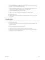
Paper Adjustment Controls
The printer paper loading controls for the floor cabinet model are shown in Figure 2-4. The
printer paper loading controls for the pedestal model are shown in Figure 2-5. The controls
are the Forms Thickness Adjustment Lever (A), the Vertical Position Knob (B), the Horizontal
Adjustment Knob (C), and the paper tractors (D). The PAPER ADVANCE switch on the conĆ
trol panel is also used during the paper loading procedure.
Operation
2-7
Figure 2-4. Paper Adjustment Controls - Floor Cabinet Model
2-8
Operation
Figure 2-5. Paper Adjustment Controls - Pedestal Model
Forms Thickness Adjustment Lever - The Forms Thickness Adjustment Lever, shown in
Figure 2-6, controls the platen gap. Raising the lever opens the platen and lowering the lever
closes the platen to adjust for various paper thicknesses. The scale indicates approximate posiĆ
tioning to correspond with paper thickness (1 to 6 part forms). Generally, set the lever for a
slight friction on the paper as it moves past the hammer bank. If the Forms Thickness AdjustĆ
ment Lever is set incorrectly, the print hammer flight timing can be upset, resulting in waviness
of vertical lines (called poor phasing). When fully raised, the platen is open to allow paper loadĆ
ing and ribbon replacement; a platen open message is shown on the display. After lowering the
lever to the appropriate operating position, press CLEAR FAULT on the Control Panel to
clear the platen open condition.
Operation
2-9
Figure 2-6. Forms Thickness Adjustment Lever
Vertical Position Knob - The Vertical Position Knob, shown in Figure 2-7, moves the paper
up or down. The platen must be open (Forms Thickness Adjustment Lever fully raised) to use
this control.
Figure 2-7. Vertical Position Knob
2-10
Operation
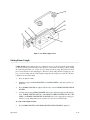
Horizontal Adjustment Knob - The Horizontal Adjustment Knob, shown in Figure 2-8,
shifts the paper left or right up to approximately !/3 inch. This control is used to make fine
adjustments to the left margin. Once adjusted, further adjustments are usually not required.
Figure 2-8. Horizontal Adjustment Knob
Tractors - The paper tractors feed the paper through the printer. The position of the left tracĆ
tor, shown in Figure 2-9, establishes the left paper margin. Normally, the left tractor is posiĆ
tioned for the left print margin (first character position) to align with character column 1 on the
paper scale (on top of the ribbon deck cover). Once properly positioned, further adjustments
are not required unless a change is made to the left print margin. Margins can also be estabĆ
lished by control codes from the host computer. Refer to the Programming chapter. The right
tractor position is adjusted to compensate for various paper widths. Both tractors are locked in
position during normal operation and must be unlocked to make any position adjustment. To
unlock the tractor, simply raise or lower the tractor lock to the center position and slide the
tractor as necessary. If the tractor has screw-type locks, simply rotate the knobs to lock/unlock
the tractor. Once in position, be sure to lock the tractor again.
Operation
2-11
Figure 2-9. Left Paper Tractor
Loading Paper
P6000L/P6200L Series printers use standard fanfold paper from 3 to 16 inches wide and 15 to
100 lb bond (0.025 inches thick maximum). To load paper, perform the following steps and refer
to Figure 2-10.
1.
Place the printer offline and raise the top cover.
2.
Fully raise the Forms Thickness Adjustment Lever (A).
3.
Open both tractor gates (B) by swinging them out.
4.
On floor cabinet models, open the front cover and feed the paper up through the paper
slot (C) from below. On pedestal models, feed the paper up through the paper slot (C) in
the pedestal or table from below. On both models, push the paper up until it appears
above the ribbon mask (D). If the paper snags, fold the top edge down before feeding.
5.
Load the paper on the tractor sprockets (E); close the tractor gates (B). If necessary to
slide the right tractor to remove paper slack or to adjust for various paper widths, release
the right tractor lock (F) by raising or lowering it to the center; slide the tractor into posiĆ
tion. After positioning the tractor, lock it in place.
NOTE: The left tractor should remain locked in alignment with the number 1" on the
paper scale to set the left margin with the first character space.
2-12
Operation
6.
Press TOP OF FORM or PAPER ADVANCE to further advance paper into the paper
stacking area. Verify unobstructed paper feeding.
7.
Set the Forms Thickness Adjustment Lever (A) to approximate the paper thickness (1 to 6
parts). If closed too tightly, the shuttle may smear or tear the paper.
8.
Press CLEAR FAULT and place the printer online.
9.
Set the top-of-form as described in the Setting Top-of-Form procedure.
10. Close the printer cover.
11. On floor cabinet models, perform the Paper Stacking instructions to start the paper stackĆ
ing properly.
Unloading Paper
1.
Place the printer offline.
2.
Tear off the paper below the paper guide. On pedestal model printers, this will be at the
bottom of the printer.
3.
Fully raise the Forms Thickness Adjustment Lever.
4.
Open both tractor gates and remove the paper from the tractor sprockets.
5.
Gently pull the paper up through the paper slot. Be careful not to let paper perforations or
sprocket holes catch on the ribbon mask.
Operation
2-13
Figure 2-10. Loading Paper
2-14
Operation
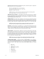
Setting Top-of-Form
Top-of-form determines where the first line of print will appear and should be set when paĆ
per is loaded. Generally, set the first line of print about one-half inch below the paper perforaĆ
tion or where application requirements dictate.
After the top-of-form is set, the paper can be advanced to the top of the next form by pressing
the TOP OF FORM switch. Unless specifically altered, P6000L/P6200L Series printers assume
11-inch length paper is used. For alternate length forms, refer to the Setting Forms Length
section.
Use the following procedure to set the top-of-form.
1.
Place the printer offline.
2.
Fully raise the Forms Thickness Adjustment Lever (A) to position the top of the first line
to be printed at the top of the black TOP-FORM mark on the left tractor gate as shown in
Figure 2-11.
3.
Set the Forms Thickness Adjustment Lever to approximate the paper thickness (1 to 6
parts). If closed too tightly, the shuttle may smear or tear the paper.
4.
Press Clear Fault to clear the PLATEN OPEN condition.
5.
Press SET TOF.
NOTE: Pressing SET TOF at any other time will reset the top-of-form position.
6.
Place the printer online.
Figure 2-11. Setting Top-Of-Form
Operation
2-15
Paper Stacking - Floor Cabinet Models
The floor cabinet model is capable of stacking up to one complete box of standard computer
paper when the paper is properly loaded. After loading the paper, perform the following inĆ
structions.
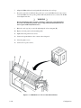
1.
Open the rear cabinet door to access the paper stacking area.
NOTE: Steps 2 and 3 pertain to installation of the two paper stacking fences, the front
fence between the paper stack and the paper supply and the rear fence on the rear cabinet
door. If these fences have already been installed, continue with the paper stacking inĆ
structions at step 4.
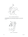
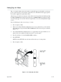
2.
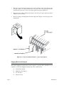
If not previously installed, install the front paper fence in the bracket as close as possible
to the paper stacking area as shown in Figure 2-12. The bracket is located in the upper
portion of the printer paper stacking area near the outer edges. The fence must be inĆ
stalled in the same bracket position on each side to maintain a straight vertical orientaĆ
tion.
Figure 2-12. Front Paper Fence Installation - Floor Cabinet Models
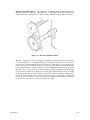
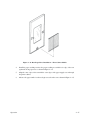
3.
2-16
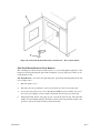
If not previously installed, install the rear paper fence on the inside of the rear cabinet
door placing the fence in the brackets at each upper edge of the door and in the bracket
centered on the lower edge of the door as shown in Figure 2-13.
Operation
Figure 2-13. Rear Paper Fence Installation - Floor Cabinet Models
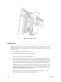
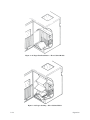
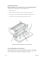
4.
Install the paper stacking tent into the paper stacking area with the far edge of the tent
against the front paper fence as shown in Figure 2-14.
5.
Align the outer edges of the tent with the outer edges of the paper supply as seen through
the printer cabinet.
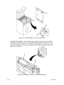
6.
Advance the paper until a few sheets begin to stack on the tent as shown in Figure 2-15.
Operation
2-17
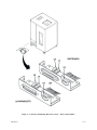
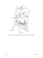
Figure 2-14. Paper Tent Installation - Floor Cabinet Models
Figure 2-15. Paper Stacking - Floor Cabinet Models
2-18
Operation
7.
Verify the following and make any necessary adjustments.
a. The paper stack is centered on the tent.
b. The paper perforation folds are folding in their natural prefolded direction.
c. The paper is following a straight path down to the tent in alignment with the outer
edges.
d. The paper is against the front paper fence as it rests centered on the tent.
8.
Run the printer and let approximately 15 to 20 sheets of paper stack.
9.
Again verify the items listed in step 7. Any adjustments to the paper stack can be made
while the printer is running. If an adjustment is made, again check the stack after approxiĆ
mately 15 to 20 sheets have been processed.
NOTE: If the paper is not stacking properly, check the following items in addition to
those listed in step 7.
1.
If printing occurs across the paper perforations, the paper will not stack corĆ
rectly. Adjust the Skip Over Perforation configuration parameter to eliminate
printing across the paper perforations.
2.
If the paper path is too close to either side panel, paper stacking can be disĆ
rupted. Adjust the paper path toward the center of the printer, away from the
side panels.
3.
The front paper fence may be incorrectly positioned. Reposition the front paĆ
per fence into one of the other bracket locations.
Selecting Print Mode
Characters and symbols are printed based on the print mode selected. During normal operaĆ
tion, the message display indicates the printer is online and the print mode currently selected.
For example,
ON LINE
DP AT 10 CPI *
indicates the Data Processing print mode at 10 characters per inch is selected. To select a print
mode, perform the following instructions.
1.
Place the printer offline.
2.
Simultaneously press RUN/STOP TEST and CONFIG MENU to unlock the printer conĆ
figuration.
3.
Press PRINT MODE; the display will show the current print mode.
4.
Repeatedly press PRINT MODE until the required print mode is displayed.
5.
Press RUN/STOP TEST to select the displayed print mode.
6.
Press CLEAR FAULT to return to OFFLINE READY.
Operation
2-19
7.
Simultaneously press RUN/STOP TEST and CONFIG MENU again to lock the printer
configuration. Place the printer on line.
Additional printing capabilities and character attributes can be used by sending the appropriĆ
ate control codes to the printer from the host computer as described in the Programming chapĆ
ter. Print mode control from the host computer will override the control panel setting.
Loading the Ribbon
Each printer is shipped with an OCR (extra dark) ribbon. The ribbon should be replaced when
the print contrast is too light or approximately after each box of standard size computer paper.
To replace the ribbon, perform the following steps and refer to Figure 2-16.
1.
Place the printer offline and raise the top cover.
2.
Fully raise the Forms Thickness Adjustment Lever (A) to open the platen.
3.
Unlatch each ribbon spool (B) and carefully lift them off the hubs (C). Raise the ribbon
out of the ribbon path. Properly discard the used ribbon.
4.
Place each new ribbon spool (B) on a hub (C) with the ribbon to the outside. The ribbon
rewinds automatically; either ribbon spool can be loaded on either hub.
5.
Press the spools down until the latch (D) snaps in place.
6.
Thread the ribbon around the ribbon guides (E) and through the ribbon path as shown in
the diagram (F) on the ribbon deck cover. The ribbon must pass between the two thin meĆ
tallic strips called the hammer bank cover (G) and the ribbon mask (H).
NOTE: The ribbon must not be twisted in the ribbon path. A twisted ribbon can lower
print quality, shorten ribbon life, or cause a paper jam.
2-20
7.
Lower the Forms Thickness Adjustment Lever (A) to the appropriate operating position.
8.
Press CLEAR FAULT on the control panel to clear the platen open condition.
9.
Close the top cover and place the printer online.
Operation
Figure 2-16. Ribbon Replacement
Setting Forms Length
P6000L/P6200L Series printers may use continuous, tractor-fed paper with the forms length
set in inches (between 1.0 and 24.0) or lines (between 1 and 192 at 6 or 8 lines per inch). Setting
the forms length in lines at 6 or 8 lpi does not change the line spacing. The printer has been
preset for standard 11-inch length paper. Therefore, when using alternate length paper, the
top-of-form setting and the forms length setting must be changed to match the alternate
length. To set the forms length:
1.
Place the printer offline.
2.
Simultaneously press RUN/STOP TEST and CONFIG MENU to unlock the printer conĆ
figuration.
3.
Press FORMS LENGTH; the display will show the current FORMS LENGTH SET IN
INCHES.
4.
Continuously pressing FORMS LENGTH will step the display through the following opĆ
tions: FORMS LENGTH SET IN 6 LPI LINES, FORMS LENGTH SET IN 8 LPI
LINES, and FORMS LENGTH SET IN INCHES. Choose the appropriate setting, perĆ
form the corresponding instructions, and then save the selected forms length.
To set the forms length in inches:
5.
Operation
Press FORMS LENGTH until FORMS LENGTH SET IN INCHES is displayed.
2-21
6.
Press CONFIG VALUE to dislay the current forms length in inches.
7.
Continue pressing CONFIG VALUE to increment the forms length by 0.5 inch or simulĆ
taneously press CONFIG VALUE and CONFIG MENU to decrement the forms length
by 0.5 inch. After the appropriate value is displayed, save it as described below.
To set the forms length in lines:
8.
Press FORMS LENGTH until FORMS LENGTH SET IN 6 LPI LINES or 8 LPI LINES
is displayed.
9.
Press CONFIG VALUE to dislay the current forms length in lines.
10. Continue pressing CONFIG VALUE to increment the forms length by 1 line or simultaĆ
neously press CONFIG VALUE and CONFIG MENU to decrement the forms length by
1 line. After the appropriate value is displayed, save it as described below.
To save the displayed forms length:
11. Press RUN/STOP TEST to select the displayed forms length.
12. Press CLEAR FAULT to return to OFFLINE READY.
13. Simultaneously press RUN/STOP TEST and CONFIG MENU to lock the printer conĆ
figuration.
14. Set the top-of-form using the Setting Top-of-Form instructions.
Forms length in inches can also be set by control code from the host computer. Forms length
control from the host computer will override the control panel setting.
Setting Line Spacing
P6000L/P6200L Series printers can be set for a line spacing of 6 or 8 lines per inch (lpi) from the
control panel using the LINE SPACING switch. To select the line spacing from the control
panel, perform the following steps.
1.
Place the printer offline.
2.
Press LINE SPACING; the display will show the current line spacing.
3.
Press LINE SPACING again to display and select the alternate line spacing.
4.
Press CLEAR FAULT to return to OFFLINE READY. Place the printer on line.
Line spacing can also be selected by sending line spacing control codes from the host computer.
Using control codes, line spacing other than 6 or 8 lpi is available. Line spacing control from the
host computer will override the control panel setting.
2-22
Operation
Hex Code Printout
The hex code printout (called a hex dump) provides a listing of ASCII character data sent from
the host with their corresponding two-digit hex code. Nonprintable characters are indicated
with a period symbol. A p" before the hex code indicates an active Paper Instruction (PI) line;
a blank space before the hex code indicates an inactive PI line. To print the data stream sent
from the host computer in hex code with ASCII character equivalents, perform the following
steps.
1.
Place the printer offline.
2.
Repeatedly press CONFIG MENU until the DIAGNOSTICS message is displayed.
3.
Press CONFIG VALUE; CONFIGURATION PRINTOUT will be displayed.
4.
Press CONFIG MENU; PRINT DATASTREAM IN HEX CODE will be displayed.
5.
Press RUN/STOP TEST; the display will be OFFLINE HEX DUMP.
6.
Press ONLINE. The display will indicate ONLINE HEX DUMP.
7.
Send the data from the host; the hex dump will print.
8.
Press ONLINE again to stop the hex dump. Press RUN/STOP TEST to exit HEX DUMP.
Repeatedly press CLEAR FAULT to return to OFFLINE READY.
9.
Place the printer online.
Operation
2-23
Printer Reset
The printer can be reset to the power-up configuration values whenever necessary. To reset
the printer, simply press CLEAR FAULT and RUN/STOP TEST simultaneously. The proceĆ
dure resets the printer to the configuration values last saved, not factory default values.
Running the Self-Test
P6000L/P6200L Series printers include various self-test functions. Use the self-test as
needed to determine if the printer is functioning normally.
To run the self-tests:
1.
Place the printer offline.
2.
Repeatedly press CONFIG MENU until DIAGNOSTICS is displayed.
3.
Press CONFIG VALUE; CONFIGURATION PRINTOUT will be displayed.
4.
Repeatedly press CONFIG MENU until either PRINTER TEST 8 INCH WIDTH or
PRINTER TEST FULL WIDTH is displayed.
5.
Repeatedly press CONFIG VALUE until the appropriate test is displayed. Tests include
shift recycle, all Es, and others.
6.
Press RUN/STOP TEST to begin the selected self-test; press RUN/STOP TEST again to
stop the test.
Examine the print quality. The characters should be solidly formed and aligned. If not, there
may be a problem with the printer.
2-24
7.
Repeatedly press CLEAR FAULT to place the printer offline.
8.
Place the printer online.
Operation
CHAPTER 3
CONFIGURATION
Introduction
Configuration refers to a set of operating parameters that define how the printer will respond
to commands sent from the host computer. Most all the configuration parameters are selected
from the control panel as shown on the Control Panel Switch Function Diagrams. A few conĆ
figuration parameters are hardware selectable by jumpers on the Logic C board as described in
the Hardware Jumper Configuration section.
Before reconfiguring any printer function, be sure to read this entire chapter. The following
information is presented:
n
Lock/Unlock Printer Configuration
n
Configuration Menus
n
Configuration Procedure
n
Set/Save/Load Configuration Values
n
Default Configuration Values
n
Configuration Printout
n
Hardware Jumper Configuration
n
Control Panel Switch Function Diagram
Locking/Unlocking Printer Configuration
As previously described in the Operation chapter, the printer configuration is locked to preĆ
vent accidental or unintentional reconfiguration. Pressing the RUN/STOP TEST and CONĆ
FIG MENU switches simultaneously will alternately unlock or lock the printer configuration.
The Printer configuration must be unlocked to reconfigure the printer from the control panel.
NOTE: While DATA IN BUFFER is present, the printer configuration will remain
locked. Press PAPER ADVANCE, TOP-OF-FORM, or ONLINE to empty the printĆ
er's buffers and remove the DATA IN BUFFER condition.
Configuration Menus
The CONFIG MENU switch accesses and displays the various control panel selectable conĆ
figuration menus. The individual parameter values within each menu are displayed by repeatĆ
edly pressing the CONFIG VALUE switch. The following configuration menus appear on the
message display:
D
Configuration
Ribbon Life
3-1
D
Character Set
D
Application Compatibility
D
Paper Format
D
Host Interface
D
Load Parameters
D
Save Parameters
D
Diagnostics
From these menus, the related configuration parameter values can be displayed and selected.
Configuration Procedure
Most configuration options can be selected from the control panel. The few hardware selecĆ
table configuration options are described in the Hardware Jumper Configuration section. To
verify or modify the configuration from the control panel, the printer must be powered up, ofĆ
fline (OFFLINE READY), and the printer configuration unlocked to select parameters in the
configuration menus.
Basic configuration procedure requires alternately pressing the CONFIG MENU and CONĆ
FIG VALUE switches to arrive at the desired parameter. The use of these switches and an illusĆ
tration of the configuration menus are described in the Control Panel Switch Function
Diagram section of this chapter. Thoroughly review the diagram to understand the configuraĆ
tion menu hierarchy and the control panel switches necessary to access and display individual
menus and parameter values.
The following general procedure can be used to reconfigure the printer from the control panel
as necessary to meet application requirements. Detailed descriptions are provided following
the general procedure.
3-2
1.
Simultaneously press RUN/STOP TEST and CONFIG MENU to unlock the printer conĆ
figuration.
2.
Obtain a current configuration listing as described in the Configuration Printout section
of this chapter.
3.
Determine the parameter values that must be changed to meet requirements. Refer to the
Control Panel Switch Function Diagram for an illustration of the parameter values and
the procedure required to select and display the values.
4.
Select and display the required value(s).
5.
Enter the value(s) by pressing the RUN/STOP TEST switch.
6.
Save the value(s) as the current default (if desired) as described in the Set/Save/Load
Configuration Value section of this chapter.
7.
Simultaneously press RUN/STOP TEST and CONFIG MENU again to lock the printer
configuration.
8.
Place the printer online. The selected values are effective.
Configuration
Set/Save/Load Configuration Values
Configuration values can be stored for temporary use or saved for more permanent use as the
power-up default configuration. In addition, current power-up default values can be loaded
(restored) for use as needed.
Set Values
Any configuration value can be changed as needed to meet application requirements. In order
to change a configuration parameter, the printer configuration must be unlocked. Select the
new value of the configuration parameter and press the RUN/STOP TEST switch. An asterisk
(*) will appear to the right of the value to indicate its selection.
NOTE: This type of change is only temporary. To permanently change a configuration
parameter, refer to the Save Values section of this chapter.
For example, to temporarily change the forms length parameter to 14.0 inches, unlock the
printer configuration and select and display a forms length value of 14.0 inches. Press the RUN/
STOP TEST switch to enter the value. 14.0 inches will now be used as the forms length parameĆ
ter.
Values stored in this way are replaced by the power-up default (saved) values when the printer
power is turned off and on. If a particular value is only required for a short term, limited appliĆ
cation, it can be stored temporarily. If the value is required for more permanent repeated use,
it should be saved as a power-up default.
Saved Values
Saved configuration values are the power-up default values. These are the parameters effecĆ
tive when the power is turned on. Until another value set is saved, the Printronix default conĆ
figuration values are effective at the initial power-up after receiving the printer from the
factory. The following general procedure can be used to save configuration values. Refer to the
Control Panel Switch Function Diagram for an illustration of the control panel switches reĆ
quired to select and display the parameter menus and values.
1.
Unlock the printer configuration by simultaneously pressing the RUN/STOP TEST and
CONFIG MENU switches.
2.
Select the value(s) required as the power-up defaults using the RUN/STOP TEST switch
to enter the change(s).
NOTE: Changing the Printer Compatibility under the Application Compatibility menu
affects other parameter value choices, automatically disabling some values and resetting
others. It also sets the current paper position as the top of form. Consequently, if the
Printer Compatibility configuration parameter is changed, it must be changed before
changing any other parameter values. Values changed prior to changing the Printer ComĆ
patibility value may be cancelled and not saved with the value set.
3.
Select and display SAVE PARAMETERS.
Configuration
3-3
4.
Press RUN/STOP TEST. All currently selected values are saved as the power-up default
value set.
5.
Press CLEAR FAULT once to return to OFFLINE READY.
6.
Lock the printer configuration by simultaneously pressing the RUN/STOP TEST and
CONFIG MENU switches, and place the printer online.
The saved values remain effective until specifically changed by storing or saving other values. It
is important to remember that all currently selected values are saved, not just the specific value
most recently changed. Note also that values changed by control code sequences will also be
saved. For example, if the print mode is changed by control code and the configuration values
are subsequently saved, the print mode change is also saved. However, horizontal tab posiĆ
tions, margin settings, and character attributes such as bold, double high, etc. that can be
changed by control code but are not reflected on the display are not saved with the configuraĆ
tion value set.
Load Values
The current power-up default configuration value set can be loaded (restored) as needed. If,
for example, a number of configuration values were changed and stored for temporary use, the
complete power-up default set can be restored. This provides a convenient method of resetĆ
ting the printer's configuration to known values. The following general procedure can be used
to load (restore) the power-up default values.
3-4
1.
Unlock the printer configuration by simultaneously pressing the RUN/STOP TEST and
CONFIG MENU switches.
2.
Select and display LOAD PARAMETERS.
3.
Repeatedly press CONFIG VALUE until the LOAD DEFAULT PARAMETERS mesĆ
sage is displayed.
4.
Press RUN/STOP TEST. The current power-up default values are restored and in effect.
5.
Press CLEAR FAULT once to return to OFFLINE READY.
6.
Lock the printer configuration and place the printer online.
Configuration
Default Configuration Values
The printer comes from the factory with a set of Printronix default configuration values as listed
in Table 3-1. These values are operational when the printer is received from the factory. New
values can be selected and stored or saved as necessary for each application.
Table 3-1. Printronix Default Configuration Values
CONFIGURATION
PARAMETER
DEFAULT
VALUE
CONFIGURATION
PARAMETER
DEFAULT
VALUE
Forms Length
Print Mode
Line Spacing
11.0 Inches
DP 10 cpi
6 lpi
Job Rate
Ribbon Size
When Worn Action
350
60
Stop Printer
Character Set
ASCII
RibbonMinder Action
Disable
Printer Protocol
Buffer Size
P-Series
2048 characters
Printer Select
Paper Advance Switch
Disable
Print + Paper Advance
Automatic Line Feed
Define CR Code
After Full Line
CR = CR
Slew Relative
1 to 16
Host Interface
Centronics
Define LF Code
LF = CR + LF
Data Polarity
Standard
Uppercase/Lowercase
Upper and Lower
Response Polarity
Standard
Special Function Character
Disable
Data Protocol
XON/XOFF
VFU Select
Paper Motion Detector
EVFU
Enable
Data Rate
Word Length
9600
8 Bits
Power On State
Online
Stop Bit
One
Mod Plot
Disable
Parity
None
Unidirectional Printing
Disable
Bit 8 Function
Font
Perforation Skip
Disable
CD and DSR
Disable
Paper Fault Stop
End of Paper
CTS and DSR
Disable
Data Line 8
Enable
Data Term Ready
Online and BNF
PI Line
Disable
Request to Send
Online and BNF
Fast Busy
Enable
Reverse Channel
Online and BNF
Configuration
3-5
Configuration Printout
The configuration printout lists all of the currently selected configuration parameter values. A
sample configuration printout is shown in Figure 3-1.
The following general procedure can be used to obtain a configuration printout. Refer to the
Control Panel Switch Function Diagram for an illustration of the switches required to select
and display the parameter menus and values.
3-6
1.
Verify the POWER indicator is lit and the printer is off line.
2.
Repeatedly press CONFIG MENU until DIAGNOSTICS is displayed.
3.
Press CONFIG VALUE; select and display the CONFIGURATION PRINTOUT menu.
4.
Press RUN/STOP TEST. The configuration printout will be produced.
5.
Press RUN/STOP TEST again to return to OFFLINE READY.
Configuration
Figure 3-1. Sample Configuration Printout
Configuration
3-7
Hardware Jumper Configuration
Jumpers on the Logic C board are used to select a few configuration parameters. These jumpĆ
ers are installed for normal operation at the factory. However, certain applications may reĆ
quire a modification to the jumper configuration. To change any of these configuration
jumpers, the C3 logic board must be removed. Table 3-2 describes the jumper configurations.
To access the Logic C PCBA in floor cabinet model printers, the right side panel must be reĆ
moved and the card cage lowered. The following procedures provide instructions on accessing
the Logic C PCBA for both the floor cabinet and pedestal models.
-
WARNING -
Any of these hardware changes require attention to detail on the PCBA assembly to
prevent damage. Some configurations require cutting an etch on the PCBA and solĆ
dering. These changes should only be performed by a trained technician.
Side Panel Removal - Floor Cabinet Model
To remove the right side panel, perform the following instructions and refer to Figure 3-2.
3-8
1.
Turn the printer off and disconnect the ac power cord.
2.
Raise the printer cover.
3.
Disconnect the two ground wire connectors (A) from the corners of the side panel.
4.
Loosen the side panel release screw (B) with the Phillips head screwdriver. Do not reĆ
move the screw; simply loosen it enough to slide in the notched cutout on the frame.
5.
Using both hands, lift the side panel up and out from the bottom edge. The panel fits
snugly on four mounting studs (C). First time removal of the side panel may require extra
pressure to unseat the studs from the panel keyholes (D). The card cage can now be acĆ
cessed.
Configuration
Figure 3-2. Side Panel Removal - Floor Cabinet Model
Removing the PCBA - Floor Cabinet Model
After removing the side panel, the card cage can be accessed. To remove the Logic C PCBA
from the card cage, perform the following instructions and refer to Figure 3-3.
1.
To lower the card cage (A), loosen but do not remove the release wing nut (B) on the right
side of the card cage and gently pull the front edge of the cage down.
2.
Locate the Logic C PCBA (C); the names of the PCBAs are printed on the card cage.
3.
Cut the tie wrap restraints (D) if present.
4.
Snap out the top and bottom ejector levers (E) to release the PCBA from the edge conĆ
nector.
5.
Gently slide the PCBA out of the card cage.
6.
Make or verify the required jumper configuration change(s). See Table 3-2 on page
3-13.
Configuration
3-9
7.
Align the PCBA with its slot and gently slide it back into the card cage.
8.
Press the ejection levers (E) back into position to secure the PCBA into the edge connecĆ
tor. If the PCBA does not go into position with only moderate force, remove the PCBA
and realign it in its slot.
-
WARNING -
Forcing the PCBA back into position can damage components or break the PCBA.
Never force the PCBA into position; always realign and reinstall the PCBA if it canĆ
not be replaced with only moderate force.
9.
Raise the card cage (A); secure it by tightening the release wing nut (B).
10. Replace the side panel on the mounting studs.
11. Tighten the side panel release screw.
12. Connect the ground wires to the corners of the side panel.
13. Close the printer cover.
14. Connect the ac power source.
Figure 3-3. PCBA Removal - Floor Cabinet Model Printer
3-10
Configuration
Logic C PCBA Removal and Replacement - Pedestal Model Printer
Perform the following instructions and refer to Figure 3-4 to remove and replace the Logic C
PCBA.
1.
Turn the printer off and disconnect the ac power cord.
2.
Turn the two captive screws (A) at the top of the rear panel to unlock it. Lower the rear
panel.
3.
Swing the card cage (B) out from the back of the printer.
4.
Locate the Logic C PCBA (C); the names of the PCBAs are printed on the card cage.
5.
Cut the tie wrap restraints (D) if present.
6.
Snap out the top and bottom ejector levers (E) to release the PCBA from the edge conĆ
nector.
7.
Gently slide the PCBA out of the card cage.
8.
Make or verify the required jumper configuration change(s). Refer to Table 4-2.
9.
Align the PCBA with its slot and gently slide it back into the card cage.
10. Press the ejection levers (E) back into position to secure the PCBA into the edge connecĆ
tor. If the PCBA does not go into position with only moderate force, remove the PCBA
and realign it in its slot.
-
WARNING -
Forcing the PCBA back into position can cause damage to the components or break
the PCBA. Never force the PCBA back into position; always try to realign and reinĆ
stall the PCBA if a large amount of pressure must be exerted.
11. Swing the card cage (B) back into the printer.
NOTE: It is not necessary to replace the tie wrap restraints on the ejector
levers.
12. Raise the rear panel and secure it with the two screws.
13. Reconnect the ac power cord and turn the printer on.
Configuration
3-11
Figure 3-4. PCBA Removal - Pedestal Model Printer
3-12
Configuration
Table 3-2. Hardware Jumper Configuration
JUMPER LOCATION
DESCRIPTION
E3-E6
E4-E7
E5-E8
E6-E9
E7-E10
E8-E11
E14-E15
E18-E19
E20-E21
E32-E33
E34-E35
E36-E37
E38-E39
NTXCLK Input - Serial Interface Transmit Clock *
NRXCLK Input - Serial Interface Receive Clock *
NEXTCLK Input - Serial Interface External Clock *
Clock to TC Input - Serial Interface *
Clock to RC Input - Serial Interface *
Timer C Output to Clock - Serial Interface *
Dataproducts Strobe Polarity
In = Inverted
P6X80 Select
In = P6X80
Out = P6X40
P6X80 NRESYNC Timer
Must be IN for P6X80
P6X80 Phase Fire Enable
Must be IN for P6X80
27256 E-PROM 0
Must be IN
CPU Clock
Must be IN
P6X40 Hammer Load
Must be IN for P6X40
E39-E40
E45-E46
E49-E50
E50-E51
E52-E53
P6X80 Hammer Load
27256 Font PROM 0
Data Latch Edge Select
Data Latch Edge Select
ACK Edge Select
Must be IN for P6X80
Must be IN
In = Leading Edge
In = Trailing Edge
In = Leading Edge
*NOTE: Only one of the Serial Interface clocks can be selected by inserting the related
jumper. Selecting one of these clocks may require cutting the related etch on the PCBA:
For jumper E5-E8, cut E8-E11; for jumper E4-E7, cut E7-E10; for jumper E3-E6,
cut E6-E9. Any of these changes should only be performed by a qualified technician.
Configuration
3-13
Control Panel Configuration Diagram
The Control Panel Configuration Diagram is a series of block diagrams that show the configuĆ
ration menus and the parameters available within each menu. Boxes on the diagram represent
the message display; the message that appears on the display is printed inside the box. The letĆ
ters outside the boxes and adjacent to the directional arrows represent control panel function
switches. When the indicated switch is pressed, the arrow leads to the displayed result of pressĆ
ing that switch. The symbols used on the Control Panel Configuration Diagram are shown in
Figure 3-5.
The diagram is presented in 3 levels, each level illustrating a particular set of parameter menus
and values. The relationships between the three levels are shown in Figure 3-6.
Level I - Print Format
Line Spacing
Print Mode
Forms Length
Level II - Main Configuration Menus
Ribbon Life
Character Set
Application Compatibility
Paper Format
Host Interface
Load Parameters
Save Parameters
Diagnostics
Level III - Configuration Menu Parameters
3-14
Printer Protocol
Paper Empty
Buffer Size
PMD Fault
Uppercase Select
Modified Plot
Printer Select
Slew Relative
Paper Advance Switch
Centronics Interface Parameters
Power-On State
Dataproducts Interface Parameters
Unidirectional
Serial RS-232 Interface Parameters
Auto Line Feed
Configuration Printout
Define CR Code
Print Data In Hex Code
Define LF Code
Printer Test 80 Column Paper
VFU Select
Printer Test 132 Column Paper
Perforation Skip
Print Statistics
Configuration
CONTROL PANEL CONFIGURATION
DIAGRAM SYMBOLS:
CONTROL PANEL
MESSAGE
DISPLAY
OL = PRESS
ON LINE
ON LINE
FL = PRESS
FORMS
LENGTH
LS = PRESS
LINE
SPACING
PM = PRESS
PRINT
MODE
CM = PRESS
CONFIG
MENU
POWER
PAPER
ADVANCE
MESSAGE
DISPLAY
FORMS SET UP
FORMS
LENGTH
CONFIG
VALUE
CV = PRESS
RUN/STOP
TEST
R/S = PRESS
(to change
parameter)
CONFIG
MENU
PV = PRESS
(previous)
CONFIG
CONFIGURATION
LOCKED / UNLOCKED
MENU
(Enables R/S switch
for configuration changes)
SET
TOF
PRINT FORMAT
CLEAR
FAULT
CF = PRESS
TOP OF
FORM
+
+
LINE
SPACING
PRINT
MODE
CONFIG
MENU
CONFIG
VALUE
RUN/STOP
TEST
CLEAR
FAULT
CONFIG
VALUE
RUN/STOP
TEST
*= FACTORY DEFAULT PARAMETER
= ARROWS LEAD TO
THE DISPLAYED
RESULT AFTER
PRESSING THE
INDICATED SWITCH
+ = PRESS SWITCHES
SIMULTANEOUSLY
Figure 3-5. Control Panel Configuration Diagram Symbols
Configuration
3-15
ON LINE
DP AT 10 CPI
,
*
OL
NOTE: The message CONFIGURATION LOCKED
will be displayed when entering
LEVEL I or LEVEL II if the
OFFLINE
printer configuration is locked
READY
or the DATA IN BUFFER
message is displayed.
,
OL
NOTE: Factory default print mode
shown for illustration only.
Print Mode is an option set
by the user.
NOTE: Press OL in any submenu
(except when diagnostic tests
are running) to enter the
ON LINE state.
CM
LS, PM, FL
LEVEL I
LEVEL II
CF
CF
Print Format
CM
Main
Configuration
Menus
(Sheet 16)
(Sheet 17)
LS, PM, FL
NOTE: PRINT MODE, LINE SPACING
or FORMS LENGTH menus may be
accessed from ANY other menu, at
any time, except when running
diagnostic tests.
CV
CF
LEVEL III
Configuration
Menu
Parameters
(Sheets 18 - 27)
LS, PM, FL
Figure 3-6. Control Panel Overview
3-16
Configuration
*
Configuration
LINE SPACING
SET AT 8 LPI
LS
LINE SPACING
SET AT 6 LPI
CF
CF
PM
PV
PRINT MODE
HS AT 13 CPI
PV
HS AT 12 CPI
HS AT 10 CPI
NLQ AT 17 CPI
NLQ AT 15 CPI
NLQ AT 13 CPI
NLQ AT 12 CPI
NLQ AT 10 CPI
DP AT 17 CPI
DP AT 15 CPI
DP AT 13 CPI
PM
CF
CF
CF
FL
*
CV
PV
CV
FORMS LENGTH
RANGE IS FROM
1.0 TO 24.0
INCHES IN 0.5
INCH INCREMENTS
PV
FORMS LENGTH SET
AT 11.0 INCHES
CV FORMS LENGTH SET
AT 10.5 INCHES
PV
CV
CF
PV FORMS LENGTH SET
IN INCHES
OFFLINE
READY
*
CF
CF
CF
FL
PV
*
CV
PV
CV
FORMS LENGTH
RANGE IS FROM
1 TO 192 LINES
PV
FORMS LENGTH SET
AT 66 LINES
CV FORMS LENGTH SET
AT 65 LINES
PV
CV
CF
FORMS LENGTH SET
IN 6 LPI LINES
Control Panel Switch Function Diagram (Sheet 1 of 12)
PM
*
PM
DP AT 12 CPI
PV
PRINT MODE
DP AT 10 CPI
LS
OL
ON LINE
DP AT 10 CPI
LEVEL I - PRINT FORMAT
CF
CF
CF
FL
PV
*
CV
PV
CV
FORMS LENGTH
RANGE IS FROM
1 TO 192 LINES
PV
FORMS LENGTH SET
AT 88 LINES
3-17
CV FORMS LENGTH SET
AT 87 LINES
PV
CV
CF
FORMS LENGTH SET
IN 8 LPI LINES
CF
CF
CF
FL
CM
CF
SHEET 3
A
CV
*
CF
Configuration
PV
RIBBON LIFE xxx %
CM
OFFLINE
READY
OL
DP AT 10 CPI
ON LINE
CM
PV
P
SHEET 4
B
CV
CHARACTER SET
CF
CF
CF
SHEET 5
C
CV
APPLICATION
COMPATIBILITY
CF
CM
PV
CF
SHEET 6
D
CV
PAPER FORMAT
CF
CM
CM
PV
CF
G
SHEET 11
CF
CV
DIAGNOSTICS
CF
SHEET 7
E
CV
CF
HOST INTERFACE
Control Panel Switch Function Diagram (Sheet 2 of 12)
CM
PV
NOTE: If configuration changes are to be made,
the printer configuration must be unlocked by
simultaneously pressing the CM and R/S switches.
LEVEL II - MAIN CONFIGURATION MENUS
PV
CM
CM
PV
CF
CF
(1) Returns after 1
second
SAVE PARAMETERS
VALUES SAVED
R/S
SAVE PARAMETERS
CF
SHEET 12
F
CV
LOAD PARAMETERS
(1)
PV
CM
3-18
PV
PV
CF
CM
PV
CF
*
CV
Press CV / PV to
increment / decrement
NEW RATE by 1
CURRENT xxx
NEW RATE xxx
CF
RIBBON LIFE xxx %
SET JOB RATE
Configuration
CF
Press R/S to enter
the Job Analysis mode
(1)
R/S
RIBBON LIFE xxx %
ANALYZE JOB
CM
PV
CF
*
CV
(1)
Press CV / PV to
increment / decrement
NEW RATE by 10
CURRENT xxx
NEW SIZE xxx
CF
RIBBON LIFE xxx %
SET RIBBON SIZE
CV
PV
PV
CV
CM
PV
CF
*
RIBBON LIFE xxx %
VISUAL ALARM
PV
RIBBON LIFE xxx %
AUD/VIS ALARM
PV
RIBBON LIFE xxx %
STOP PRINTER
CV
RIBBON LIFE xxx %
WHEN WORN ACTION
CV
CV
Control Panel Switch Function Diagram (Sheet 3 of 12)
PV
CF
CF
CF
CM
installed before printing resumes, (before or after entering this menu selection), or a FAULT CONDITION CHANGE RIBBON will occur.
CM
PV
(2) The xxx% will disappear from all RIBBON LIFE xxx% menus while the ribbon action is disabled.
(1) A new ribbon must be
NOTE: Press CM in any
submenu to go to the next
menu. (For example, press CM
in the NEW RATE submenu
to go to the ANALYZE JOB menu.)
Press R/S to reset
ribbon life to 100% (1)
R/S
RIBBON LIFE xxx %
NEW RIBBON
CV
RIBBON LIFE xxx %
A
FROM SHEET 2
LEVEL III - CONFIGURATION MENU PARAMETERS
CF
*
CV or PV
RIBBON LIFE xxx %
ENABLE ACTION
(2)
RIBBON LIFE xxx %
DISABLE ACTION
CV
RIBBON LIFE xxx %
ENABLE / DISABLE
3-19
CF
CF
CM
PV
Configuration
PV
*
CF
CV
PV
CV
PV
CF
CHARACTER SET
FRENCH
CV
PV
CF
CHARACTER SET
GERMAN
CV
PV
CF
CV
PV
CF
CV
PV
CF
CHARACTER SET
SPANISH
CV
PV
CHARACTER SET
JAPANESE
Control Panel Switch Function Diagram (Sheet 4 of 12)
CHARACTER SET
ITALIAN
CF
CHARACTER SET
ENGLISH
NOTE: Press CM in any submenu to go to the Application Compatibility menu.
CHARACTER SET
SWEDISH
CF
CHARACTER SET
ASCII
CV
CHARACTER SET
B
FROM SHEET 2
CV
PV
CF
CV
PV
CHARACTER SET
FRENCH CANADIAN
CF
CHARACTER SET
DANISH
CV
PV
CV
PV
3-20
CV or PV
PRINTER PROTOCOL
P-SERIES
*
PROTOCOL
PV
Configuration
CF PRINTER PROTOCOL
SERIAL MATRIX
CF
CV
PRINTER
CF
PV
CM
CV
PV
CF
BUFFER SIZE
1024 CHARACTERS
CV
BUFFER SIZE
512 CHARACTERS
CV
BUFFER SIZE
2048 CHARACTERS
CV
BUFFER SIZE
PV
PV
*
CF
CF
CF
CM
PV
CF
CF
CF
*
PRINTER SELECT
ON=DC1 / OFF=DC3
CV or PV
PRINTER SELECT
DISABLE
CV
PRINTER SELECT
PV
CF
CF
CM
CF
*
PAPER ADVANCE SW
MOVE PAPER ONLY
CV or PV
PAPER ADVANCE SW
PRINT + PAP ADV
CV
PAPER ADVANCE SW
Control Panel Switch Function Diagram (Sheet 5 of 12)
NOTE: Press CM in any submenu
to go to the next menu. (For example,
press CM in any submenu of PAPER
ADVANCE SW to go to the
POWER ON STATE menu.)
UPPERCASE SELECT
UPPERCASE ONLY
CF
CM
PV
APPLICATION
COMPATIBILITY
*
CV or PV
UPPERCASE SELECT
UPPER & LOWER
CV
UPPERCASE SELECT
CV
C
FROM SHEET 2
CF
CF
CM
PV
*
POWER ON STATE
ON LINE
CV or PV
POWER ON STATE
OFF LINE
CV
POWER ON STATE
CF
CF
CM
PV
CF
*
CM
3-21
UNIDIRECTIONAL
PLOT
CV or PV
UNIDIRECTIONAL
DISABLE
CV
UNIDIRECTIONAL
CF
CF
PV
CM
PV
CF
PAPER EMPTY
IMMEDIATE
CV or PV
PAPER EMPTY
END OF PAPER
CV
PAPER EMPTY
*
CF
CM
PV
CF
PMD FAULT
DISABLE
CV or PV
*
PMD FAULT
ENABLE
CV
PMD FAULT
CM
*
MODIFIED PLOT
ENABLE
CV or PV
MODIFIED PLOT
DISABLE
CV
MODIFIED PLOT
(3)
(1)
CF
CM
PV
CV
PV
CM
PV
PAPER FORMAT
SLEW RELATIVE
1 TO 15
CV or PV
*
SLEW RELATIVE
1 TO 16
CV
SLEW RELATIVE
CF
VFU SELECT
DISABLE
PV
VFU SELECT
DAVFU
PV
*
VFU SELECT
EVFU
CV
VFU SELECT
CF
D
(3)
CV
CV
(3)
CM
(2)
CF
CF
CM
FROM SHEET 2
Control Panel Switch Function Diagram (Sheet 6 of 12)
CF
PV
CF
DEFINE LF CODE
LF = LF
DEFINE CR CODE
CR = CR + LF
*
CV or PV
CV
CV or PV
CF
DEFINE LF CODE
CF
DEFINE LF CODE
LF = CR + LF
*
CF
CM
PV
DEFINE CR CODE
CR = CR
CV
DEFINE CR CODE
CF
NOTE: Press CM in any submenu to go the next menu.
(For example, press CM in any AUTO LINE FEED submenu
to go to the DEFINE CR CODE menu.)
AUTO LINE FEED
DISABLE
Configuration
CM
CM
PV
CF
*
CF
PV
CV or PV
AUTO LINE FEED
AFTER FULL LINE
CV
AUTO LINE FEED
CF
CV
PV
CV
PV
CV
CV
CV
CV
CF
CM
PV
PV
(3) NOT APPLICABLE message box is displayed in
Serial Matrix protocol.
(2) Only the SERIAL VFU message box is displayed in
Serial Matrix protocol.
3-22
(1) Message box is not displayed in P-Series protocol.
PERFORATION SKIP
1 INCH
PV
PERFORATION SKIP
5/6 INCH
PV
PERFORATION SKIP
2/3 INCH
PV
PERFORATION SKIP
1/2 INCH
PV
*
PERFORATION SKIP
DISABLE
CV
PERFORATION SKIP
CF
CM
CF
Continued
below
Configuration
PV
CV
CF
CV
DATA BIT 8
DISABLE
*
CV
CF
PV
PV
CF
PI LINE
ENABLE
PI LINE
DISABLE
CV
PI LINE
CM
CM
CV or PV
*
CF
CM
PV
DATA POLARITY
INVERTED
CV or PV
DATA POLARITY
STANDARD
CV
*
PV
DATA POLARITY
SHEET 8
FOR DATAPRODUCTS MENUS
PV
H
CF
CF
I
CF
CM
PV
*
RESP. POLARITY
INVERTED
Control Panel Switch Function Diagram (Sheet 7 of 12)
CF
CM
PV
FAST BUSY
DISABLE
FAST BUSY
ENABLE
CV
FAST BUSY
CV or PV
*
CF
CM
NOTE: Press CM in any submenu
to go to the next menu. (For example,
press CM in any submenu of
DATA POLARITY to go to the
RESP POLARITY menu.)
CV or PV
RESP. POLARITY
STANDARD
CV
RESP. POLARITY
CM
SHEET 9
FOR SERIAL
RS-232 MENUS
NOTE: The strobe and ack edge are selected by hardware jumper.
CM
*
HOST INTERFACE
CENTRONICS
DATA BIT 8
ENABLE
CV or PV
E
HOST INTERFACE
DATA BIT 8
FROM SHEET 2
3-23
Configuration
CM
DATA BIT 8
DISABLE
DATA BIT 8
ENABLE
CV
DATA BIT 8
CV
CV or PV
*
CF
HOST INTERFACE
DATAPRODUCTS
CM
PV
PI LINE
DISABLE
PI LINE
ENABLE
CV
PI LINE
CF
CV or PV
*
FROM SHEET 7
CF
CM
PV
*
DATA POLARITY
INVERTED
CV or PV
DATA POLARITY
STANDARD
CV
DATA POLARITY
CF
CF
CM
PV
*
RESP. POLARITY
INVERTED
CV or PV
RESP. POLARITY
STANDARD
CV
RESP. POLARITY
CF
Control Panel Switch Function Diagram (Sheet 8 of 12)
The strobe and ack edge, and strobe polarity are selected by hardware jumper.
NOTE: Press CM in any submenu
to go to the next menu. (For example,
press CM in any submenu of DATA BIT 8 to go to the PI LINE menu.)
CF
PV
H
CF
CM
3-24
CF
Configuration
DATA PROTOCOL
DTR, RC, OR RTS
PV
DATA PROTOCOL
ACK / NAK
PV
DATA PROTOCOL
ETX / ACK
PV
DATA PROTOCOL
X-ON / X-OFF
PV
CV
DATA PROTOCOL
CV
HOST INTERFACE
SERIAL RS-232
CV
CV
CV
CV
*
CF
PV
CM
I
PV
DATA RATE
19200 BAUD
PV
DATA RATE
9600 BAUD
PV
DATA RATE
4800 BAUD
PV
DATA RATE
2400 BAUD
PV
DATA RATE
1200 BAUD
PV
DATA RATE
600 BAUD
PV
DATA RATE
300 BAUD
PV
DATA RATE
150 BAUD
P
DATA RATE
CF
FROM SHEET 7
CV
CV
CV or PV
CF
CM
PV
STOP BIT
TWO
*
STOP BIT
ONE
CV
STOP BIT
CF
CV or PV
CF
CM
PV
PARITY
EVEN
PARITY
ODD
PARITY
NONE
PV
PARITY
PV
PV
*
CV
CF
A protocol to stop the host data must be chosen. If a data protocol
of DTR, RC, or RTS is chosen, at least one of the following must be
configured to assert when either the printer's buffers are full (BF)
or not full (BNF):
DATA TERM READY, REQUEST TO SEND, or REVERSE CHANNEL.
In this case, the cable from the host must also carry that control line.
NOTE: Press CM in any submenu to go to the next menu.
(For example, press CM in any submenu of DATA PROTOCOL
to go to the DATA RATE menu.)
WORD LENGTH
7 BITS
*
WORD LENGTH
8 BITS
CV
WORD LENGTH
CF
Control Panel Switch Function Diagram (Sheet 9 of 12)
*
CV
CV
CV
CV
CV
CV
CF
CM
PV
CV
CV
CV
CF
CM
CF
PV
Continued
on next page
3-25
PV
CM
PV
CM
CF
CM
CF
CV
BIT 8 FUNCTION
IGNORE
PV
BIT 8 FUNCTION
PI LINE
PV
BIT 8 FUNCTION
FONT SELECT
PV
(1)
BIT 8 FUNCTION
CV
CV
CV
*
CF
Configuration
(1) Not applicable for a 7-bit word.
PV
Continued from
previous page
CM
PV
CF
CD AND DSR
ENABLE
CF
CM
PV
CF
CTS AND DSR
ENABLE
CV or PV
*
CTS AND DSR
DISABLE
CV
CTS AND DSR
CF
CM
PV
CF
DATA TERM RDY
TRUE
PV
DATA TERM RDY
FALSE
PV
DATA TERM RDY
OFFLINE OR BF
PV
DATA TERM RDY
ONLINE AND BNF
PV
CV
DATA TERM READY
CV
CV
CV
*
CV
CF
CM
PV
CF
CF
*
CV
CV
CV
CV
REQUEST TO SEND
TRUE
PV
REQUEST TO SEND
FALSE
PV
REQUEST TO SEND
OFFLINE OR BF
PV
REQUEST TO SEND
ONLINE AND BNF
CV
REQUEST TO SEND
PV
Control Panel Switch Function Diagram (Sheet 10 of 12)
When CD and DSR is enabled, both CD and DSR must be asserted
for the printer to receive data. When CTS and DSR is enabled, both
CTS and DSR must be asserted before the printer can send protocol
characters, such as xoff or xon, to the host.
NOTE: Press CM in any submenu to go to the next menu.
(For example, press CM in any submenu of DATA TERM READY
to go to the REQUEST TO SEND menu.)
CV or PV
CV
*
CD AND DSR
DISABLE
CD AND DSR
CM
PV
CF
CM
CF
CV
CV
CV
*
CV
3-26
REVERSE CHANNEL
TRUE
PV
REVERSE CHANNEL
FALSE
PV
REVERSE CHANNEL
OFFLINE OR BF
PV
REVERSE CHANNEL
ONLINE AND BNF
PV
CV
REVERSE CHANNEL
PV
CF
(1)
PV
CV
PV
CM
CF
RUNNING TEST
ALL E'S
R/S
ON LINE
HEX DUMP
OFF LINE
HEX DUMP
R/S
OL
PRINT DATASTREAM
IN HEX CODE
CF
FROM SHEET 2
PRINTER TEST
ALL E'S
PV
G
CV
CF
PV
CF
CF
CV
RUNNING TEST
E PLUS TOF
R/S
PRINTER TEST
8 INCH WIDTH
PRINTER TEST
E PLUS TOF
CM
PV
CV
Configuration
PV
CF
CF
CV
PRINTER TEST
FULL WIDTH
RUNNING TEST
ALL H'S
R/S
PRINTER TEST
ALL H'S
CM
CV
CF
CV
PV
CF
CF
RUNNING TEST
SHUTTLE/RIBBON
RUNNING TEST
DEMONSTRATION
PRINTER TEST
SHUTTLE/RIBBON
RUNNING TEST
BLACK PLOT
R/S
R/S
PV
CV
CF
PRINTER TEST
BLACK PLOT
CM
R/S
PRINTER TEST
DEMONSTRATION
CF
RUNNING TEST
UNDERLINE ONLY
R/S
PV
CF
CV
SHEET 12
J
CV
PRINT STATISTICS
PRINTER TEST
UNDERLINE ONLY
CM
PV
Control Panel Switch Function Diagram (Sheet 11 of 12)
NOTE: The black plot self-test automatically prints unidirectionally
to avoid thermal damage to the hammer bank.
PV
CF
NOTE: Press CM in any menu to go to the PRINTER TEST FULL WIDTH
(if in PRINTER TEST 8 INCH WIDTH) or PRINT STATISTICS (if in
PRINTER TEST FULL WIDTH) menu.
RUNNING TEST
SHIFT RECYCLE
R/S
PRINTER TEST
SHIFT RECYCLE
CF
(1) Returns after completion
of printout.
CONFIGURATION
PRINTING
R/S
CONFIGURATION
PRINTOUT
CV
DIAGNOSTICS
PV
CF
CV
3-27
Configuration
CF
POWER ON TIME
XXXX.X HRS
CV
PRINT STATISTICS
J
FROM SHEET 11
PV
CV
PV
(1)
(1) Returns after 1 second
FACTORY PARAMETR
LOADED
R/S
LOAD FACTORY
PARAMETERS
CV or PV
CV
PV
CF
SHUTTLE STROKES
X,XXX,XXX,XXX
CV
PV
CF
PRINT LINES
X,XXX,XXX,XXX
DEFAULT PARAMETR
LOADED
R/S
LOAD DEFAULT
PARAMETERS
Control Panel Switch Function Diagram (Sheet 12 of 12)
PRINT TIME
XXXXX.X HRS.
CF
NOTE: Press CM in any submenu of PRINT STATISTICS
to go to the CONFIGURATION PRINTOUT menu.
NOTE: Press CM in any submenu
of LOAD PARAMETERS to go to
the DIAGNOSTICS menu.
CF
CV
LOAD PARAMETERS
F
FROM SHEET 2
(1)
CV
CF
PV
CF
PRINT PAGES
X,XXX,XXX,XXX
CV
3-28
CHAPTER 4
GRAPHICS
Introduction
All P6000L/P6200L Series printers are capable of standard Printronix Odd/Even Dot Plotting
for normal and high density graphics as well as Bit Image graphics with single, double density,
and double speed double density modes. Odd/Even dot plotting is available for graphics when
the printer is in the P-Series mode; Bit Image graphics is used when the printer is in the Serial
Matrix mode. Printing text and characters is the default mode of operation. Consequently,
each line of graphics data must include a graphics control code to enable the printer for the
desired graphics mode of operation.
The following graphics information is presented in this chapter:
n
Serial Matrix Compatible Bit Image Graphics
n
P-Series Compatible Plot Mode
n
Combining Graphics and Text
Serial Matrix Compatible Bit Image Graphics
Bit Image graphics is used with the printer in the IBM Graphics Printer Serial Matrix mode. Bit
Image Graphics are created by printing a series of vertical Bit Image data bytes which represent
the binary code bit pattern. The Bit Image mode utilizes the 1" or true bits from a binary data
byte to print dot patterns. These data bytes are actually the binary equivalent of ASCII characĆ
ter decimal values 0 through 255. For example, the binary data byte bit pattern for the ASCII
character A" (hex 41, decimal 65) is shown below in Figure 4-1.
MSB
Figure 4-1. Binary Data Byte
If this data byte is rotated vertically, the result is a vertical data byte pattern with the most sigĆ
nificant bit (MSB) at the top as shown in Figure 4-2.
Graphics
4-1
MSB
MSB
Figure 4-2. Vertical Data Byte Pattern
If each 1" or true bit is plotted, the result is a Bit Image plot of the ASCII character A". The
relationship of ASCII character, decimal value, and Bit Image plot is shown in Figure 4-3.
ASCII
CHARACTER
A
BINARY
CODE
EQUIVALENT
DECIMAL
VALUE
=
65
=
128
64
32
16
8
4
2
1
TO
VERTICALLY
ROTATED DATA
BYTE
BIT IMAGE
PATTERN
MSB
=
Figure 4-3. Bit Image Pattern from an ASCII Character
Any byte, such as the one in the previous example, can be identified by its binary, octal, hexaĆ
decimal, or decimal equivalent and subsequently used to generate a Bit Image pattern. A table
of the standard ASCII character set and equivalences is included in Appendix A. Use this table
to quickly identify the various equivalences of ASCII characters. Bit Image plotting is not limĆ
ited to printable ASCII characters; Bit Image patterns can be plotted for any 8-bit data byte
with decimal values ranging from 0 to 255.
NOTE: Printing solid black bit image for extended periods will overheat the hammer
bank.
4-2
Graphics
Plotting a Bit Image Pattern
A Bit Image pattern can be developed as follows:
1.
Layout the graphic to be printed on a quadrille pad or graph paper.
2.
Determine the decimal equivalence of each Bit Image data byte required to produce the
pattern.
3.
Write a program to generate the complete pattern.
4.
Enter and run the program on the host computer.
Figure 4-4 illustrates steps 1 and 2. Eight vertical cells are used to create the Bit Image pattern
corresponding to the eight bits of the vertically rotated data byte. Dots are placed in the cells to
provide a visual representation of the graphic to be printed. Each dot corresponds to a 1" or
true bit in the data byte. In this example, seven Bit Image data bytes are required to create the
dot pattern. These seven data bytes must be specified in the written program (step 3) to generĆ
ate the entire pattern.
1st BIT IMAGE DATA BYTE
2nd BIT IMAGE DATA BYTE
7th BIT IMAGE DATA BYTE
DECIMAL
WEIGHTS
128
64
32
16
8
4
2
1
73
36
146
36
255
73
146
DECIMAL
VALUES
Figure 4-4. Bit Image Pattern Plan
A Bit Image pattern is easily defined by determining the decimal equivalent of the binary data
byte. This decimal value may then be included in a program data statement that generates the
final Bit Image pattern. To determine the decimal value of a data byte, each dot's decimal
weight is added together. For the seven bytes shown in Figure 4-4, the decimal values are comĆ
puted as shown in Table 4-1.
Graphics
4-3
Table 4-1. Example Bit Image Pattern Decimal Values
BIT IMAGE
DATA BYTE
DECIMAL WEIGHT
DECIMAL VALUE
1 st byte
64 + 8 + 1
= 73
2 nd byte
128 + 16 + 2
= 146
3 rd byte
32 + 4
= 36
4 th byte
128 + 64 + 32 + 16 + 8 + 4 + 2 + 1
= 255
5 th byte
32 + 4
= 36
6 th byte
128 + 16 + 2
= 146
7 th byte
64 + 8 + 1
= 73
Bit Image Density
Bit Image graphics may be printed in different dot densities selected by control code.
Control code ESC K selects the Single Density mode.
Control code ESC L selects the Double Density mode.
Control code ESC Y selects the Double Speed, Double Density mode.
Control code ESC Z selects the Quadruple Density mode.
In Single Density Bit Image graphics from the Data Processing print mode, printed dot density
is 60 dots per inch (dpi) horizontal and 72 dpi vertical. From the Correspondence print mode,
horizontal dot density is 120 dpi and vertical density is 144 dpi.
The Double Density mode prints up to twice the number of dots per inch horizontally (up to
120 dpi from the Data Processing mode). The vertical dot density remains the same as in the
Single Density mode. Double horizontal density requires twice the number of input data bytes
to print the same length line as Single Density. Printing the additional dots reduces the printing
speed by half.
When the Double Density, Double Speed control code is received, the data can be printed up
to double the current horizontal dot density but all adjacent dots are removed which will affect
the final density of the printed image. Since double density graphics are printed at half speed,
double density double speed graphics are printed at the same speed as single density graphics.
Quadruple Density graphics is printed by pairing adjacent bit image bytes. The paired data is
then printed in the Double Density mode
4-4
Graphics
Bit Image Programming Format
The syntax of the Bit Image expression must be correct. The expression must include the apĆ
propriate dot density control code, the exact number of data to be plotted, and the data itself.
The general Bit Image expression is:
ESC,CC,(n1),(n2),DATA
where:
ESC
= the Serial Matrix compatible header
CC
= K, L, or Y to select dot density; K = single, L = double,
Y = double density double speed, and Z = quadruple density
n1, n2
= define the number of data bytes to be printed
DATA
= the dot pattern bytes
The values for n1 and n2 must be specified in the control code expression. They are defined as:
n1 = number of data bytes MOD 256
n2 = INT (number of data bytes\256)
The modulus arithmetic operator MOD refers to the integer value that is the remainder of an
integer division. The INT operator refers to integer division and is denoted by the backslash \.
Therefore, n1 is the remainder of the number of data divided by 256 and n2 is the integer value
of the number of data divided by 256.
n1 = (number of data bytes)-(n2 x 256)
n2 = (number of data bytes)\256
If the number of data bytes to be printed is less than 256, n2 equals zero and n1 equals the numĆ
ber of data bytes to be printed.
The following examples illustrate the procedure to determine the Bit Image program stateĆ
ment.
Print 450 data bytes, single density
n2 = 450\256 = 1
n1 = 450-(1x256) = 194
The program statement is:
ESC K (194)(1)(DATA)
Print 700 data bytes, single density
n2 = 700\256 = 2
n1 = 700-(2x256) = 700-512 = 188
The program statement is:
ESC K (188)(2)(DATA)
Print 180 data bytes, single density
n2 = 180\256 = 0
n1 = 180-(0x256) =180-0 = 180
Graphics
4-5
The program statement is:
ESC K (180)(0)(DATA)
The number of data bytes and the n1, n2 definition must be equal. If too few data bytes are sent,
printing will not begin until sufficient data is received. Any characters following n1 and n2 will
be interpreted and plotted as data until the n1, n2 definition is satisfied.
If excess data is received, only the defined amount will be plotted. Excess data will be interĆ
preted as printable characters or control codes. The maximum number of data bytes (when usĆ
ing 132 column paper) that can be included in the DATA portion of the program statement
varies according to the operating mode. At 60 dpi, Single Density = 792 bytes; Double Density
= 1584 bytes.
A detailed description of the individual Bit Image control codes with examples is provided in
the Programming chapter.
NOTE: Depending on the host computer system, it may be necessary to include a width
statement within the BASIC program.
The following sample program written in BASIC produces Single Density Bit Image graphics
of the pattern shown in Figure 4-4. The 7 data bit pattern is repeated 40 times. The printed
result of running the program is shown in Figure 4-5.
10 LPRINT ”Single Density Bit Image Graphics”
20 LPRINT CHR$(27);”K”;CHR$(24);CHR$(1);
30 FOR N=1 TO 40
40 RESTORE
50 FOR I=1 TO 7
60 READ R
70 LPRINT CHR$(R);
80 NEXT I
90 NEXT N
100 DATA 73, 146, 36, 255, 36, 146, 73
110 LPRINT
Figure 4-5. Sample Single Density Bit Image Graphics
4-6
Graphics
P-Series Compatible Plot Mode
This part of the Graphics chapter describes the P-Series compatible odd/even dot Plot mode
of operation. Plot mode allows any individual dot position to be addressed and printed. This
enables you to produce a variety of graphics including bar codes, complex curve graphs, pie and
bar charts, block characters, or halftones. The plot commands indicated in this section may also
be accessed in the Serial Matrix mode.
Plot Density
Plot density refers to the number of dots per inch (dpi) printed in a single dot row. Two types of
plot density are available with P-Series Plot mode graphics: normal density and high density.
The densities can be mixed within the printed page on a dot row-by-row basis, but the two
densities cannot be mixed on the same dot row.
Normal density plotting is selected with the odd dot plot control code ENQ (05 hex). The odd
numbered dot columns are addressed to produce a horizontal and vertical density that varies
based on the mode of operation: 60 dpi horizontal and 72 dpi vertical for Data Processing (DP)
mode, 120 dpi horizontal and 144 dpi vertical for Correspondence (NLQ) mode, and 60 dpi
horizontal and 48 dpi vertical for High Speed mode. Figure 4-6 illustrates normal density dot
plot.
Figure 4-6. Normal Density Plot
High density plotting is selected with the even dot plot control code EOT (04 hex) in conjuncĆ
tion with the odd dot plot control code ENQ (05 hex). The odd and even numbered dot colĆ
umns are addressed to double the horizontal density with a maximum of 1584 dots in a single
dot row. The vertical density remains the same in normal and high density plotting. Figure 4-7
illustrates high density plotting.
Figure 4-7. High Density Plot
NOTE: When printing black plot for extended periods, enable unidirectional plot to preĆ
vent overheating the hammer bank.
Graphics
4-7
Plot Data Line Format
A P-Series compatible plot data line contains a maximum of 132 data bytes, a plot mode conĆ
trol code, and a line terminator as shown in Figure 4-8. The first data byte in the line addresses
the dot positions to print in the first character column; the second data byte addresses the dot
positions to print in the second character column, etc.
The P-Series Plot mode control code is either odd dot plot (05 hex) or even dot plot (04 hex),
depending on the desired plot density, and should occur before any of the data bytes. The line
terminator used is commonly a line feed (0A hex), but a form feed (0C hex) can also be used.
VFU commands cannot be used as a line terminator in the Plot mode.
For normal density plot, the odd dot plot control code is sent along with the data bytes and a
line terminator. In odd dot plot, a line feed control code used as the line terminator causes the
contents of the buffer to be plotted and advances the paper a single dot row based on the vertiĆ
cal density of the current mode. If a form feed control code is used as the line terminator, the
contents of the buffer are plotted and the paper is advanced to the next top-of-form position.
The printer then defaults to the print mode.
For high density plot, the even dot plot and odd dot plot control codes are used in conjunction
with two data lines. The even dot plot control code is sent with the first data line along with the
line terminator. The line terminator, either a form feed or a line feed, causes the contents of
the buffer to be plotted in the even dot columns but does not advance the paper. The printer
waits for the second line of data using the odd dot plot control code and a line terminator. If a
line feed control code is used as the line terminator of the second line, data in the buffer is plotĆ
ted in odd dot columns of the same row where even dot column data was just plotted, paper is
advanced one dot row (at the vertical density of the current mode), and the printer defaults to
the print mode. If a form feed is used as the line terminator of the second data line, the same
action occurs except the paper is advanced to the top of the next form rather than one dot row.
PLOT MODE
1st CHAR
2nd CHAR
3rd CHAR
132nd CHAR
LINE TERMINATOR
0011111
1111111
1100001
0000111
0A HEX=
LINE FEED
05 HEX =
NORMAL
DENSITY PLOT
OR
OR
04 HEX + 05 HEX =
HIGH
DENSITY PLOT
0C HEX=
FORM FEED
s s
FFFFFFFFFFFF
BIT 1
FF
BIT 1
BIT 6
BIT 6
Figure 4-8. Plot Data Line Format
4-8
Graphics
Plot Data Byte Format
Each data byte specifies six of the twelve dot columns that compose one character column. UsĆ
ing odd dot plot, bits 1 to 6 of the data byte address the odd numbered dot columns; using even
dot plot, bits 1 to 6 of the data byte address the even numbered dot columns. Bit 6 and/or bit 7 of
the data byte must be a 1" (or true) bit in the Plot mode. Bit 8 of the data byte is not used in the
Plot Mode and can be either 1 or 0.
As shown in Figure 4-9, a dot is printed at the location addressed by each of bits 1 to 6 in the
data byte that is set (1 or true). Consequently, the binary equivalent of the plot data bytes must
be known to accurately address specific dot positions. Table 4-2 presents the binary equivaĆ
lents and resultant dot patterns of the standard ASCII characters.
ODD DOT PLOT DATA BYTE
LSB
BIT 1
DOT COLUMN
NO.12 OF
PREVIOUS
CHARACTER
COLUMN
NOTE:
BIT 6 AND/OR
BIT 7 MUST BE
A 1 FOR PLOT
MODE
BIT 2
BIT 3
BIT 4
BIT 5
BIT 6
BIT 7
1 1 1 0 1 1 1
1
3
5
7
9
MSB
BIT 8
NOT
USED
11
2
4
6
8
10
12
DOT COLUMN NO. 1
OF NEXT
CHARACTER COLUMN
1 0 1 0 1 1 0
BIT 1
LSB
BIT 2
BIT 3
BIT 4
BIT 5
BIT 6
BIT 7
NOT
USED
BIT 8
MSB
EVEN DOT PLOT DATA BYTE
Figure 4-9. P-Series Plot Data Byte Format
Graphics
4-9
Graphics
4–10
OCT
040
041
042
043
044
045
046
047
050
051
052
053
054
055
056
057
060
061
062
063
064
065
066
067
070
071
072
073
074
075
076
077
BINARY
0100000
0100001
0100010
0100011
0100100
0100101
0100110
0100111
0101000
0101001
0101010
0101011
0101100
0101101
0101110
0101111
0110000
0110001
0110010
0110011
0110100
0110101
0110110
0110111
0111000
0111001
0111010
0111011
0111100
0111101
0111110
0111111
32
33
34
35
36
37
38
39
40
41
42
43
44
45
46
47
48
49
50
51
52
53
54
55
56
57
58
59
60
61
62
63
DEC
20
21
22
23
24
25
26
27
28
29
2A
2B
2C
2D
2E
2F
30
31
32
33
34
35
36
37
38
39
3A
3B
3C
3D
3E
3F
HEX
–
.
/
0
1
2
3
4
5
6
7
8
9
:
;
<
=
>
?
*
+
,
”
#
$
%
&
’
(
)
!
Space
ASCII
2 4 6 8 1012
1 3 5 7 9 11
1000000
1000001
1000010
1000011
1000100
1000101
1000110
1000111
1001000
1001001
1001010
1001011
1001100
1001101
1001110
1001111
1010000
1010001
1010010
1010011
1010100
1010101
1010110
1010111
1011000
1011001
1011010
1011011
1011100
1011101
1011110
1011111
BINARY
DEC
64
65
66
67
68
69
70
71
72
73
74
75
76
77
78
79
80
81
82
83
84
85
86
87
88
89
90
91
92
93
94
95
OCT
100
101
102
103
104
105
106
107
110
111
112
113
114
115
116
117
120
121
122
123
124
125
126
127
130
131
132
133
134
135
136
137
ASCII
40 @
41 A
42 B
43 C
44 D
45 E
46 F
47 G
48 H
49
I
4A J
4B K
4C L
4D M
4E N
4F O
50 P
51 Q
52 R
53 S
54 T
55 U
56 V
57 W
58 X
59 Y
5A Z
5B [
5C \
5D ]
5E ^
5F __
HEX
2 4 6 8 1012
1 3 5 7 9 11
Table 4–2. Plot Data Byte Dot Patterns
1100000
1100001
1100010
1100011
1100100
1100101
1100110
1100111
1101000
1101001
1101010
1101011
1101100
1101101
1101110
1101111
1110000
1110001
1110010
1110011
1110100
1110101
1110110
1110111
1111000
1111001
1111010
1111011
1111100
1111101
1111110
1111111
BINARY
140
141
142
143
144
145
146
147
150
151
152
153
154
155
156
157
160
161
162
163
164
165
166
167
170
171
172
173
174
175
176
177
OCT
96
97
98
99
100
101
102
103
104
105
106
107
108
109
110
111
112
113
114
115
116
117
118
119
120
121
122
123
124
125
126
127
DEC
60
61
62
63
64
65
66
67
68
69
6A
6B
6C
6D
6E
6F
70
71
72
73
74
75
76
77
78
79
7A
7B
7C
7D
7E
7F
HEX
Delete
}
~
r
s
t
u
v
w
x
y
z
{
h
i
j
k
l
m
n
o
p
q
‘
a
b
c
d
e
f
g
ASCII
2 4 6 8 1012
1 3 5 7 9 11
Plotting the Data
P-Series Plot mode plots the image from the horizontal bit pattern. Figure 4-10 repeats the
pattern shown in Figure 4-4 but referenced for odd dot plot. Eight vertical rows are required,
two characters per row, six columns per character. The characters required to produce the patĆ
tern were found in Table 4-2.
1st
CHARACTER
ODD COLUMNS
1
3
5
7
9 11 1
2nd
CHARACTER
ODD COLUMNS
3
1
2
3
DOT
ROW
4
5
6
7
8
5
7
1st
CHARACTER
ASCII DECIMAL
2nd
CHARACTER
ASCII DECIMAL
9 11
*
42
@
64
|
73
A
65
\
92
@
64
*
42
@
64
|
73
A
65
\
92
@
64
*
42
@
64
|
73
A
65
Figure 4-10. Odd Dot Plot Pattern Plan
The following program uses the odd dot plot control code to produce the image. The image is
printed 25 times as shown in Figure 4-11. An entire dot row is plotted in one printing pass.
Consequently, the first row of all 25 images is printed in one pass, followed by the second row,
etc, until all rows have been printed. Notice the difference between the image printed from Bit
Image graphics shown in Figure 4-5 and the image printed from odd dot plot shown in
Figure 4-11. In the odd dot plot, the second character required to produce the complete imĆ
age contains blank spaces that cause the apparent gaps between images.
10 LPRINT ”Odd Dot Plot”
20 FOR I=1 TO 8
30 READ R1
40 READ R2
50 LPRINT CHR$(5);
60 FOR N=1 TO 25
70 LPRINT CHR$(R1);CHR$(R2);
80 NEXT N
90 LPRINT
100 NEXT I
110 DATA 42, 64, 73, 65, 92, 64, 42, 64, 73, 65, 92, 64, 42, 64, 73, 65
120 LPRINT
Graphics
4-11
Figure 4-11. Sample Odd Dot Plot
Combining Graphics and Text
P6000L/P6200L Series printers are capable of combining graphics and characters (text) on the
same page in two ways: using Bit Image graphics or P-Series Plot mode to produce characters
as well as graphics and using a combination of print mode/graphics.
Any character or symbol can be created in the Plot mode or with Bit Image graphics simply by
addressing and plotting the appropriate dot positions. In this way, both graphics and text can be
produced on the same line in a single printing pass. However, Print mode is a faster, more effiĆ
cient method of producing characters.
Either Bit Image or Plot mode graphics can be mixed with text within the page on a line by line
basis. Each line of graphics data must include a graphics control code or the printer will autoĆ
matically default to the print mode. Using Bit Image graphics, it is possible to use the print
mode to produce text on one print pass followed by a print pass to produce graphics on the
same line; however, text characters can be affected by the Bit Image data when combined on
the same line.
When returning to the print mode from graphics, an extra line feed should be included in the
data stream to maintain proper line registration throughout the page. If the extra line feed is
not included, the first character line after the graphics data may be truncated as shown in
Figure 4-12.
The MODIFIED PLOT SELECT configuration option, as shown on the Control Panel Switch
Function Diagram, sheet 6 of 12 on page 3-22, will affect the translation from graphics to
print mode. MODIFIED PLOT DISABLED places the next line of text on the page as if the
current line spacing had been followed while plotting. MODIFIED PLOT ENABLED places
the next line of text on the dot row following the last dot row of plotting.
Figure 4-12. Truncated Character Line
4-12
Graphics
CHAPTER 5
VERTICAL FORMAT UNITS
Introduction
P6000L/P6200L Series printers include the Printronix standard Electronic Vertical Format
Unit (EVFU) for P-Series emulation mode, a Direct Access Vertical Format Unit (DAVFU)
if the printer has a Dataproducts interface, and a serial emulation mode Vertical Format Unit
(VFU). Each vertical format unit provides an efficient method for fast paper slewing during
repetitive printing tasks. The type of VFU used is a configuration option selected from the conĆ
trol panel. This chapter describes:
n
DAVFU
n
P-Series EVFU
n
Serial Emulation VFU
DAVFU
The DAVFU is a feature of P6000L/P6200L Series printers equipped with a Dataproducts inĆ
terface. The DAVFU permits fast paper slewing within a form of up to 143 lines in length.
A maximum of 12 channels can be assigned to each physical line of a form. Similar to programĆ
ming a normal EVFU, the user is responsible for assigning channel numbers to each line on the
form. Channel codes are then sent by the host computer to the printer resulting in rapid paper
slewing to the corresponding line.
General DAVFU Programming
The general DAVFU programming procedure is:
1.
Design the form, determining spacing and channel assignments for each line as shown in
Figure 5-1.
2.
After the form is designed, the programming sequence can be sent to the host. The basic
DAVFU sequence is:
Start Load code, channel assignments per line (requiring two data bytes per line), and the
End Load code.
Details of this procedure are described on the following pages.
Vertical Format Units
5-1
FORM DATA
PART NUMBER
PART NAME
QUANTITY
VENDOR
ADDRESS
PHONE NUMBER
FORM LINE #
1
2
3
4
5
6
7
8
9
10
11
12
DAVFU CHANNEL
1 and 12 (Top of Form)
2
3 and 8
4 and 10
5
6
7
Figure 5-1. Sample DAVFU Form Design
Start Load Code - 6E Hex
The DAVFU Start Load code is 6E (hex) with the Paper Instruction line (PI) high. This initiĆ
ates the DAVFU memory load routine. Subsequent data received is considered channel assignĆ
ments until the End Load code is received. The PI line is a hardware interface signal that is held
either high or low. Refer to the Interface chapter for PI and Data Line pinout information.
Alternatively, a Start Load Code of 6C or 6D hex may be used in place of 6E hex. When 6C is
used as the Start Load Code, line spacing will be 6 lines per minute (lpi). When 6D is used as the
Start Load Code, line spacing will be 8 lpi. When the standard 6E is used, line spacing is not
changed.
Channel Assignment
Following the Start Load code, all data bytes received are interpreted as channel assignment
data until the End Load code is received.
A maximum of 12 channels can be assigned to one physical line on the form. Two eight bit data
bytes (DAVFU characters) are required per channel assignment. Lines that have no channel
assigned also require two identifying bytes. As shown in Table 5-1, the least significant 6 bits of
the first data byte are used to assign channels 1 through 6; the least significant 6 bits of the secĆ
ond data byte are used to assign channels 7 through 12.
5-2
Vertical Format Units
Table 5-1. DAVFU Channel Assignment
FIRST DATA BYTE
CHANNEL #
BIT #
8
7
6
5
4
3
2
1 (LSB)
SECOND DATA BYTE
BIT #
CHANNEL #
8
7
6
5
4
3
2
1 (LSB)
X (don't care)
X (don't care)
6
5
4
3
2
1
X (don't care)
X (don't care)
12
11
10
9
8
7
If a bit is set, the corresponding channel is assigned. If a bit is not set, the channel is not asĆ
signed. Consequently, you must be aware of the binary equivalent of the data. For example,
assume 41 (hex) and 60 (hex) are the first two data bytes sent following the Start Load code.
41 hex = 01000001 binary
60 hex = 01100000 binary
This sequence results in channel 1 and channel 12 being assigned to line 1 of the form as shown
in Table 5-2. No other channels are assigned to line 1.
Each line on the form requires two bytes. For blank lines, the two bytes should not contain
channel assignments. That is, the data bytes sent in the load program corresponding to a blank
line on the form should not set any of bits 1 through 6.
This procedure can be continued for a maximum of 143 lines (286 DAVFU bytes). The DAVFU
ignores anything more than 286 bytes until the End Load code is received; if 572 bytes are reĆ
ceived without an End Load code, the End Load code is forced" and the load routine is termiĆ
nated.
Table 5-2. Example DAVFU Date Bytes
FIRST DATA (Load) BYTE
HEX 41
BINARY
BIT #
CHANNEL
NUMBER
VALUE
8
7
6
5
4
3
X
X
6
5
4
3
2
1
2
1
X
X
0
0
0
0
0
1 - assign ch 1 (TOF)
SECOND DATA (Load) BYTE
HEX 60
BIT #
BINARY
CHANNEL
NUMBER
VALUE
8
7
6
5
4
3
X
X
12
11
10
9
2
1
8
7
X
X
1 - assign ch 12
0
0
0
0
0
X = don't care (1 or 0)
Vertical Format Units
5-3
End Load Code - 6F Hex
The DAVFU End Load code is 6F (hex), regardless of the state of the PI line. Before the End
Load code is received during the load routine, the state of the PI line is ignored. Sending the
End Load code terminates the DAVFU memory load routine.
Using The DAVFU
Once the DAVFU program has been loaded, it can be accessed by sending the appropriate
channel instruction to the printer. The paper is slewed to the physical line on the form having
the specified channel number assigned in the DAVFU memory. This is accomplished only with
the PI line held high. For a data byte to be recognized as a DAVFU channel instruction, the
following criteria must be met:
1)
PI line must be high
2)
Data bit 5 must be 0 (not set)
Given these two conditions, the lower 4 bits of a byte will specify the DAVFU channel number.
Table 5-3 lists DAVFU channels and their equivalent data bytes.
Clearing The DAVFU Memory
The following actions will reset (clear) the DAVFU memory.
5-4
1.
Only Start Load and End Load codes are sent (no channel assignment data).
2.
An odd number of DAVFU characters (channel assignment data) are sent and are deĆ
tected after the End Load code is received. Remember, two data bytes are required per
line.
3.
A second Start Load code is received, resulting in reinitialization of the DAVFU memory
routine. This allows the routine to be restarted.
Vertical Format Units
Table 5-3. DAVFU Channel Instruction
CHANNEL
SELECTED
PI LINE
8
7
BITS OF DATA BYTE
6
5 4
3
2
1
1
X
X
X
0
0
0
0
0
2
1
X
X
X
0
0
0
0
1
3
1
X
X
X
0
0
0
1
0
4
1
X
X
X
0
0
0
1
1
5
1
X
X
X
0
0
1
0
0
6
1
X
X
X
0
0
1
0
1
7
1
X
X
X
0
0
1
1
0
8
1
X
X
X
0
0
1
1
1
9
1
X
X
X
0
1
0
0
0
10
1
X
X
X
0
1
0
0
1
11
1
X
X
X
0
1
0
1
0
12
1
X
X
X
0
1
0
1
1
1
X = don't care (1 or 0)
DAVFU/IGP Execute Form Mode
To use the DAVFU with the IGP-10 or IGP-11 in the Execute Form Mode, it must be loaded
while the IGP is in the Execute Form Mode. Consequently, the IGP must create and execute an
empty form prior to the DAVFU load routine. A typical procedure follows:
1.
Create an empty form using the IGP-10/-11 Special Function Control Character
(SFCC) and Create command. Do not create any form elements and do not use the forms
length parameter.
2.
End the Create Form Mode with the End command.
3.
Execute the form using the IGP-10/-11 Special Function Control Character (SFCC)
and Execute command. Do not use the form count or page parameters.
4.
Enter the DAVFU Start Load code.
5.
Enter the DAVFU channel assignments.
6.
Enter the DAVFU End Load code.
NOTE: Refer to the IGP-10/20/40 or IGP-11/21/41 User's Reference Manual for
forms creation and execution information
Vertical Format Units
5-5
DAVFU Line Slewing
Another method of moving paper using the DAVFU and PI line results in vertical slews of a
specified number of lines within the form, rather than slewing to a specific line. For this to ocĆ
cur, two criteria must be met:
1)
PI line must be high
2)
Data bit 5 must be 1 (set)
If these criteria are met, a specific number of lines will be slewed based on the status of data bits
1-4 as shown in Table 5-4. With bit 5 set and the PI line high, this type of vertical paper motion
will occur whether the DAVFU memory is loaded or not.
Table 5-4. DAVFU Vertical Paper Motion By Line Slewing
BITS OF DATA BYTE
6
5 4
3
2
NUMBER OF
LINES SLEWED
PI LINE
8
7
0
1
X
X
X
1
0
0
0
0
1
1
X
X
X
1
0
0
0
1
1
2
1
X
X
X
1
0
0
1
0
3
1
X
X
X
1
0
0
1
1
4
1
X
X
X
1
0
1
0
0
5
1
X
X
X
1
0
1
0
1
6
1
X
X
X
1
0
1
1
0
7
1
X
X
X
1
0
1
1
1
8
9
1
1
X
X
X
X
X
X
1
1
1
1
0
0
0
0
0
1
10
1
X
X
X
1
1
0
1
0
11
1
X
X
X
1
1
0
1
1
12
1
X
X
X
1
1
1
0
0
13
1
X
X
X
1
1
1
0
1
14
1
X
X
X
1
1
1
1
0
15
1
X
X
X
1
1
1
1
1
X = don't care (1 or 0)
5-6
Vertical Format Units
P-Series EVFU
The EVFU, a standard feature on all P6000L/P6200L Series printers, is a software controlled
vertical formatter. It allows you to preprogram frequently used lines on forms and documents
for efficient paper handling in merging operations such as invoicing or payrolling. By flagging
each line to be printed, the EVFU automatically slews the paper (rapidly advances the paper)
to the identified lines. The EVFU provides 14 channels to identify up to 132 lines. The EVFU
also allows you to slew a specific number of lines on the form.
General P-Series EVFU Programming Information
The P-Series EVFU is loaded with a program of line identification codes, one code assigned
to each line of the form. To load the memory, the host computer sends the Start Load code, a
line identification code (channel code) for each line on the form, and the End Load code. After
the memory is loaded, a line identification code occurring in the data stream enables the
EVFU to slew the paper to the identified line. The EVFU memory can be cleared by sending
just a Start Load code without channel codes or the End Load code.
Apply the following information when programming and using the EVFU.
Printer Operation During EVFU Load - The printer mechanism should not operate during
the EVFU memory load routine. If the printer starts to print or if the paper advances, an error
may occur in the load program.
Intelligent Graphics Processor - Some operation of the EVFU as described in this section
may change when the IGP option is installed. Refer to the IGP-10/20/40 or IGP-11/21/41 UsĆ
er's Reference Manual for operating parameters.
Page Perforation Skip - Loading the EVFU disables the page perforation skip.
Forms Length - Forms of any length, up to 22 inches, can be defined using the EVFU simply by
loading the EVFU memory with the desired number of lines on the form. If the printer is set for
6 lpi spacing and a 4-inch high form is to be printed with the EVFU, 24 lines must be loaded in
the EVFU memory to establish the proper forms length (4" x 6 lpi = 24 lines). Similarly, if the
same form were printed at 8 lpi, 32 lines must be loaded (4" x 8 lpi = 32 lines). If a Start Load
code is sent to clear the EVFU memory, the printer then responds to form feed codes by adĆ
vancing the paper the forms length set by printer configuration.
Line Spacing - The printer can use 6 or 8 lpi spacing with the EVFU. The EVFU calculates the
forms length by line density selected. For example, the maximum of 132 lines at 6 lpi yields a
22-inch forms length. The 6 and 8 lpi spacing should not be mixed on the same form. However,
if mixed line spacing is unavoidable, the forms length can be calculated as follows.
1.
Count the number of lines printed at 6 lpi and divide by 6; the result is in inches.
2.
Count the number of lines printed at 8 lpi and divide by 8; the result is in inches.
3.
Add the two results; this is the total forms length and should not exceed the maximum
allowable forms length which is 22 inches.
Elongated Characters - Elongated characters can be used within EVFU programs. The
EVFU automatically counts one line of elongated characters as two character lines.
Vertical Format Units
5-7
EVFU Memory Not Loaded - If the EVFU memory is not loaded, the printer will respond to
EVFU commands and channel codes sent from the host computer as a single line feed.
Paper Runaway Protection - If the EVFU memory is loaded and a channel code is sent that
was not previously loaded, the printer will move the paper a single line feed.
E Display - When the EVFU is enabled, E will be displayed on the control panel.
L Display - When the printer receives a valid load sequence, L will be displayed on the control
panel.
Channel Codes - The EVFU memory has the capacity for 132 line forms (22 inches maximum
length). The first line identification code (channel code) in the memory load program defines
the first line on the form; the second line identification code defines the second line on the
form, etc. The line identification codes used depends on the type of interface. No particular
sequence is required for the codes but each line must have a line identification code. Filler
channel codes are used for lines that will not be accessed by the print program. Any channel
code can be used as a filler except channel code 1 which defines the top-of-form. The same
filler channel code can be repeated as necessary for any number of lines.
P-Series EVFU Command and Channel Codes
The P-Series EVFU channel and command codes are loaded into the EVFU memory and
subsequently activated in one of two ways: by embedded ASCII codes in the data stream (PI
line disabled), or with the PI line and decoded interface data lines. Table 5-5 shows the EVFU
channel and commands when the PI line is used (enabled); Table 5-6 shows the EVFU chanĆ
nel and commands selected with embedded ASCII codes when the PI line is not used (disĆ
abled). The channel and command codes are described as follows.
NOTE: Sensing the PI interface line is configuration controlled.
5-8
Vertical Format Units
Table 5-5. P-Series EVFU Codes - PI Line Enabled
ASCII Codes
Hex
00
01
02
03
04
05
06
07
08
09
0A
0B
0C
0D
0E
0F
6E
6F
Dec
0
1
2
3
4
5
6
7
8
9
10
11
12
13
14
15
110
111
Data Lines
Parallel Interface
PI
1
1
1
1
1
1
1
1
1
1
1
1
1
1
1
1
1
1
7
X
X
X
X
X
X
X
X
X
X
X
X
X
X
X
X
1
1
6
X
X
X
X
X
X
X
X
X
X
X
X
X
X
X
X
1
1
5
0
0
0
0
0
0
0
0
0
0
0
0
0
0
0
0
0
0
X = Undefined, 0 or 1
4
0
0
0
0
0
0
0
0
1
1
1
1
1
1
1
1
1
1
3
0
0
0
0
1
1
1
1
0
0
0
0
1
1
1
1
1
1
2
0
0
1
1
0
0
1
1
0
0
1
1
0
0
0
0
1
1
EVFU Code Selected
1
0
1
0
1
0
1
0
1
0
1
0
1
0
1
0
1
0
1
1 (TOF)
2
3
4
5
6
7
8
9
10
11
12 (VT)
13
14
15
16
Start Load
End Load
1 = True
0 = False
Table 5-6. P-Series EVFU Codes - PI Line Disabled
ASCII Codes
Hex
10
11
12
13
14
15
16
17
18
19
1A
1B
1C
1D
1E
1F
Dec
16
17
18
19
20
21
22
23
24
25
26
27
28
29
30
31
Parallel Interface
7
X
X
X
X
X
X
X
X
X
X
X
X
X
X
0
0
X = Undefined, 0 or 1
Vertical Format Units
6
X
X
X
X
X
X
X
X
X
X
X
X
X
X
0
0
5
1
1
1
1
1
1
1
1
1
1
1
1
1
1
1
1
4
0
0
0
0
0
0
0
0
1
1
1
1
1
1
1
1
Data Lines
3
0
0
0
0
1
1
1
1
0
0
0
0
1
1
1
1
1 = True
2
0
0
1
1
0
0
1
1
0
0
1
1
0
0
1
1
EVFU Code Selected
1
0
1
0
1
0
1
0
1
0
1
0
1
0
1
0
1
1 (TOF)
2
3
4
5
6
7
8
9
10
11
12 (VT)
13
14
Start Load
End Load
0 = False
5-9
Start Load - Clears and initializes the EVFU memory for the memory load program. The
Start Load code is 1E hex when the PI line is not used or 6E hex when the PI line is used.
End Load - Terminates the memory load program. The End Load code is 1F hex when the PI
line is not used or 6F hex when the PI line is used.
Channel 1 - The top-of-form code, reserved as the first line on the form or the first line
printed (top-of-form position). The operating program sends the channel 1 code to advance
to the top of the next form.
Channels 2 through 11, 13 and 14 - Used as general channel codes, line identification codes,
or filler channels. Each line on the form must be identified by a channel code. When the operatĆ
ing program sends the channel code, the paper advances to the line identified by the channel
code. Filler channels are used to identify lines that will never be accessed by the operating proĆ
gram.
Channel 12 - Reserved as the Vertical Tab channel. The Vertical Tab code (VT, 0B hex) prints
any data in the print buffer and rapidly slews the paper to the next line identified by the channel
12 code. If channel 12 is not loaded in the EVFU memory, a single line feed will be executed
when a VT code is sent.
Form Feed - A Form Feed code (0C hex) advances the paper to the next top-of-form posiĆ
tion.
P-Series EVFU Form Definition Program
The P-Series EVFU form definition program (memory load program) is sent to the printer
from the host computer to assign channel codes to the lines of a form. The channel codes are
later accessed by the operating program to print specific data at the lines identified by the
codes. A sample EVFU form definition program is shown in Figure 5-2.
FORM LINE
NUMBER
FORM DATA
NAME
AGE
Joe Jacob Doe
45
DEPARTMENT
Manager
TITLE
ADDRESS
NUMBER
DATE
5-10
Accounting
Station E5
1759386
02/06/64
1
2
3
4
5
6
7
8
9
10
11
12
13
14
15
16
17
18
19
20
EVFU LOAD
PROGRAM
START LOAD
CH2
CH2
CH1
CH2
CH3
CH2
CH2
CH4
CH5
CH2
CH2
CH2
CH14
CH2
CH2
CH9
CH2
CH2
CH12
CH2
END LOAD
HEX CODE PI LINE
DISABLED
1E
11
11
10
11
12
11
11
13
14
11
11
11
1D
11
11
18
11
11
1B
11
1F
Vertical Format Units
Figure 5-2. Sample P-Series EVFU Form Definition Program
The format for the form definition program sent from the host computer is as follows.
1.
EVFU Start Load code.
2.
The channel 2 code is sent two times to define the first two lines of the form as fillers. AlĆ
ternatively, the channel 1 code, top-of-form, could have been the first code sent to deĆ
fine the first line of the form as the top-of-form position.
3.
The channel 1 code is sent to assign the top-of-form position to the first line printed on
the form, rather than using the top-of-form code to define the first line on the form.
4.
A series of channel codes are sent, one for each line of the form. If the form is 25 lines long,
25 channel codes must be sent. Each line to be accessed for printing by the operating proĆ
gram should have a unique channel code. Lines not to be accessed for printing by the operĆ
ating program should have a filler channel code assigned. One filler channel code can be
used for all blank" lines of the form.
5.
EVFU End Load code.
The top-of-form code can be used to identify the first line of the form, whether or not it is the
first line printed, or it can be used to identify the first line printed. In this example, the topof-form code, channel 1, is used as the line identification code of the first line to be printed,
not the first line of the form. In the case shown by the example, a Form Feed code, pushing the
TOF switch on the control panel, or sending the channel 1 code will slew paper to line 3 of the
form.
To avoid confusion, it is best to assign unique channel numbers to each line printed. If you have
an exceptionally long form with a large amount of lines, one channel code can define more than
one line. In Figure 5-1 for example, both line 5 and line 8 of the form could have been assigned
channel 4. When the host computer sends the channel 4 code the first time, the EVFU slews the
paper to line 5 and prints the AGE data. When the host computer sends channel 4 the second
time, the EVFU slews the paper to line 8 and prints the DEPARTMENT data. (If a third line
was defined by channel code 4, that line would be accessed by the next occurrence of channel
code 4 in the data stream, etc. Otherwise, the next occurrence of channel code 4 in the data
stream would cause the EVFU to slew paper to the first line identified by channel 4 on the next
form.) This procedure allows a single channel code to define more than one line on the form,
but you must be aware of which line of the form is being accessed by the number of occurrences
of the channel code in the data stream.
In the example shown in Figure 5-2, channel 2 is used repeatedly as the filler channel. The
print program would not send the channel 2 code. The lines identified by channel 2 are always
blank.
Table 5-7 defines the functions of the EVFU channels used in the Figure 5-2 example.
Vertical Format Units
5-11
Table 5-7. Example P-Series EVFU Channel Functions
FORM
LINE #
N/A
Start Load
FUNCTION
Resets EVFU memory, begins load program, sets forms
length to default.
1
ch 2
Any EVFU channel can be used as a filler (except ch 1 & 12).
In this example, ch 2 is used as the filler.
2
ch 2
Defines this line as a filler.
3
ch 1
In this example, the first line printed is assigned the TOF
channel code. This code is normally used once per form at
either the first print line or the first line of the form. A FF (form
feed code), pressing TOF, or sending ch 1 slews the paper to this line.
4
ch 4
Defines this line as a filler.
5
ch 3
Defines line 5 to be printed with AGE data.
6
ch 2
Defines this line as a filler.
7
ch 2
Defines this line as a filler.
8
ch 4
Defines line 8 to be printed with DEPARTMENT data.
9
ch 5
Defines line 9 to be printed with TITLE data.
10
ch 2
Defines this line as a filler.
11
ch 2
Defines this line as a filler.
12
ch 2
Defines this line as a filler.
13
ch 14
Defines line 13 to be printed with ADDRESS data.
14
ch 2
Defines this line as a filler.
15
ch 2
Defines this line as a filler.
16
ch 9
Defines line 16 to be printed with NUMBER data.
17
ch 2
Defines this line as a filler.
18
ch 2
Defines this line as a filler.
19
ch 12
Channel 12, Vertical Tab, defines line 19 to be printed with
DATE data. Each time a VT code or ch 12 is sent, the paper is
slewed to this position.
20
ch 2
Defines this line as a filler.
N/A
5-12
EVFU
CH.
End Load
Terminates the memory load routine.
Vertical Format Units
P-Series EVFU Line Slewing
The P-Series EVFU can also be used to slew a specified number of lines rather than slewing to
a specific line. The PI line must be enabled and set true as well as data bit 5 true to slew a numĆ
ber of lines. With the PI line true and data bit 5 true, the binary count of interface lines 1
through 4 determine the number of lines slewed as described in Table 5-8. Note that state of
data bit 5 is the difference between line slewing and using the interface lines as EVFU channel
codes; for line slewing, data bit 5 must be true but for EVFU channel codes under interface
control, data bit 5 must be false.
NOTE: If the printer is configured for the DAVFU, the binary count for line slew proĆ
duces a 0 - 15 line slew rather than 1 - 16 as shown in the table for the EVFU. The 1 16 (EVFU) or 0 - 15 (DAVFU) binary count line slew is determined based on if the
EVFU or the DAVFU is currently enabled or last enabled.
NOTE: The # of lines slewed in the P-Series EVFU may be configured via the front
panel for 1-16 or 1-15 lines.
Table 5-8. P-Series EVFU Line Slewing
DATA LINES
PI 7 6 5 4 3 2 1
1
1
1
# OF LINES SLEWED
1 - 16
1 - 15
X X 1 0 0 0 0
X X 1 0 0 0 1
1
2
3
1
1
2
4
5
3
4
1
1
X X 1 0 0 1 0
X X 1 0 0 1 1
X X 1 0 1 0 0
1
1
X X 1 0 1 0 1
X X 1 0 1 1 0
6
7
5
6
1
X X 1 0 1 1 1
8
7
1
X X 1 1 0 0 0
9
8
1
1
X X 1 1 0 0 1
X X 1 1 0 1 0
10
11
9
10
1
X X 1 1 0 1 1
12
11
1
1
1
X X 1 1 1 0 0
X X 1 1 1 0 1
X X 1 1 1 1 0
13
14
15
12
13
14
1
X X 1 1 1 1 1
16
15
X = undefined, either 1 or 0
1 = true
0 = false
Vertical Format Units
5-13
Serial Emulation VFU
In the Serial Matrix emulation mode, the VFU is basically a set of preprogrammed vertical
tabs. Various lines of the form are assigned vertical tabs which are then accessed by control
code for rapid paper advancement to the tab position. Additionally, one form can be assigned
various channels and each channel can be assigned different tab positions. This allows various
formats to be set, stored, and called as needed. Four control codes are used for the Serial mode
VFU: ESC / for channel selection, ESC b for tab setting by channel, ESC B for single channel
tab setting, and VT to execute a vertical tab. These codes and the parameters surrounding their
use are described in the Programming chapter.
Executing Vertical Tabs
The vertical tab execute code is VT. When sent, it prints the contents of the print buffer (if data
is in the buffer) and causes paper movement to the next predefined vertical tab position. If a
tab position is not defined, the paper is moved to the next line at the current line spacing. If a
tab position is at the current line, the paper is moved to the next tab position. If no tab positions
are defined between the current line and the end of the form, the paper moves to the next TOF.
Vertical Tab Positions
Vertical tab positions are set by line number. A maximum of 16 vertical tab positions can be set
per channel of the form. If the single channel format is used, a maximum of 16 vertical tabs can
be set for the form. A sample single channel format is shown in Figure 5-3. The first vertical
tab is set at line 6 for part number data, a second tab is set at line 8 for part name data, and a
third tab is set at line 14 for quantity data. Since this is a single channel format, the ESC B code
can be used to assign the vertical tabs to the lines of the form. Once the tab positions are set,
sending the vertical tab execute code (VT) causes the paper (currently at the top-of-form
position) to advance to the first tab position for PART NUMBER data. Sending another VT
moves the paper to the second tab position for the PART NAME, followed by a third VT to
access the third tab position for the QUANTITY data.
5-14
Vertical Format Units
FORM DATA
PART NUMBER
PART NAME
QUANTITY
FORM LINE
NUMBER
1
2
3
4
5
6
7
8
9
10
11
12
13
14
15
16
17
18
19
20
VERTICAL TABS
Top of Form
Tab 1
Tab 2
Tab 3
Figure 5-3. Sample Serial Matrix Vertical Tab Positions
Vertical Format Units
5-15
5-16
Vertical Format Units
CHAPTER 6
PROGRAMMING
Introduction
The P6000L/P6200L printers can be configured by the user from the control panel to respond
to Printronix P-Series or IBM Graphics Printer Serial Matrix control codes. This dual comĆ
patibility allows the programmer to choose one of two standard protocols. If equipped with the
Intelligent Graphics Processor (IGP) option, the printer will respond to the Special Function
Control Character and IGP commands as described in the IGP User's Reference Manual. This
chapter describes:
n
Overstrike Mode
n
Control Code Functions
n
Special Function Code - Control Code Header
n
Attribute Set and Reset Codes
n
Control Code Reference Index
n
Individual Control Code descriptions
Overstrike Mode
Data in the print buffer can be underlined or overstruck when the carriage return code (hex
0D) is configured for carriage return only (not carriage return and line feed). Any printable
character in the data stream can overstrike printable characters or spaces already loaded in the
print buffer as long as a paper motion command (ie: line feed, form feed) has not been reĆ
ceived. An example of overstriking and underlining characters is shown in Figure 6-1.
Enter in Print Buffer
Printed Result
P6000 SERIES PRINTER (CR)
[SP][SP]/// (CR)
_____(LF)
Key
[Sp] = Space (20 Hex)
LF = Line Feed (0A Hex)
/ / / SERIES PRINTER
P6000
CR = Carriage Return (0D Hex)*
_ = Underline (5F Hex)
* NOTE: The printer must be configured for carriage return only. If
configured for a carriage return and line feed on receipt of the CR code, the
contents of the buffer will be printed.
Figure 6-1. Overstrike/Underlining Example
Programming
6-1
Control Code Functions
The following information is listed for each code function (where applicable and possible).
ASCII Mnemonic - The standard ASCII name for the control code.
Hex Code - The code's numeric equivalent in hexadecimal.
Purpose - The function(s) of the control code.
Expression - A sample program statement written in the BASIC programming language.
Comment - A description of exceptions or limitations to normal use.
Special Function Code - Control Code Header
A Special Function Code (SFC) is used to extend the control code protocol. The SFC is the
control code introducer (or header); it is the first input in the sequence of parameters. The
general control code sequence is:
(SFC)(parameter 1)(parameter 2)...(parameter n)
P-Series codes use SOH as the control code introducer. For example, to enable bold print in
the P-Series mode, use the P-Series SFC and the bold print control code character G:
ASCII:
SOH G
Hex:
01 47
BASIC:
CHR$(1);”G”
Similarly, Serial Matrix codes use ESC as the control code introducer. For example, to enable
bold print in the Serial Matrix mode, use the Serial Matrix SFC and the bold print control code
character G:
ASCII:
ESC G
Hex:
1B 47
BASIC:
CHR$(27);”G”
NOTE: All ESC and SOH commands must be terminated by a ;" in a BASIC program
or by text following the command string. A paper motion command directly following a
special function code command may result in erroneous paper movement.
Attribute Set and Reset Codes
Certain print attributes are set and reset (turned on or off) by using the appropriate ESC or
SOH code sequence and the numbers 1 or 0. These may be either the hexadecimal code 01 and
00, or the ASCII code for the printable symbols of decimal 1 and 0 (hexadecimal code 31 and
30, respectively). Expanded Print, Super/Subscript Print, and Underline are attributes which
are set/reset in this fashion.
6-2
Programming
Control Code Reference Index
The following index lists the control codes by function and lists the ASCII mnemonic and page
number. Alphabetical listings by mnemonic and function are provided in Appendix D.
NOTE: Functions marked with a [ are available using another control code sequence
or control panel selections.
PAPER MOTION
FUNCTION
Form Feed
Line Feed
Line Feed n/216 Inch
Vertical Tab
P-SERIES
PRINTRONIX
MATRIX
(IBM Graphics Printer)
FF
LF
N/A
VT
VT
SERIAL
PAGE NO.
FF
LF
ESC J
6-57
6-27
6-33
6-34
FORMAT
FUNCTION
P-SERIES
Backspace
Cancel
Carriage Return
EVFU Commands
Forms Length Set (Inches)
Forms Length Set (Lines)
Horizontal Tab
Horizontal Tab Set
Line Spacing 1/6 Inch (6 lpi)
Line Spacing 1/8 Inch (8 lpi)
Line Spacing 8 LPI (1 line only)
Line Spacing 7/72 Inch
Line Spacing n/72 Inch (stored)
(as asserted by ESC 2)
Line Spacing n/72 Inch (asserted)
(as stored by ESC A)
Line Spacing n/216 Inch N/A
Skip-Over Perforation
Skip-Over Perforation Cancel
Vertical Tab Set
Bold Print
Bold Print Reset
Condensed Print
Condensed Print Reset
PRINTRONIX
MATRIX
SERIAL
PAGE NO.
(IBM Graphics Printer)
N/A
N/A
CR
DLE-US
N/A [
N/A [
N/A
N/A
SOH 2
SOH 0
ACK
N/A
N/A
BS
CAN
CR
N/A
ESC C NUL
ESC C
HT
ESC D
N/A
ESC 0
N/A [
ESC 1
ESC A
6-5
6-13
6-14
6-22
6-28
6-29
6-30
6-31
6-35
6-36
6-37
6-38
6-40
N/A
ESC 2
6-39
ESC 3
N/A [
N/A [
N/A
SOH G
SOH H
N/A [
N/A [
6-41
ESC N
ESC O
ESC B
ESC G
ESC H
SI (or ESC SI)
DC2
6-52
6-53
6-58
6-11
6-12
6-17
6-18
PRINT MODE (Continued)
PRINTRONIX
Programming
SERIAL
6-3
FUNCTION
P-SERIES
MATRIX
Elongated (Double High) Print (1 line)
Emphasized Print
Emphasized Print Reset
Expanded (Double Wide) Print
Expanded (Double Wide) Print Reset
Expanded (Double Wide) Print (1 line)
Overscoring
Print Mode/Pitch Selection
Superscript/Subscript Printing
Superscript/Subscript Printing Reset
Underline
PAGE NO.
(IBM Graphics Printer)
SOH d or BS
SOH E
SOH F
SOH W
SOH W
N/A
SOH _
SOH X
SOH S
SOH T
SOH -
ESC d
ESC E
ESC F
ESC W
DC4 (or ESC W)
SO (or ESC SO)
ESC _
ESC X
ESC S
ESC T
ESC -
6-19
6-20
6-21
6-23
6-23
6-24
6-42
6-48
6-54
6-55
6-56
GRAPHICS
FUNCTION
P-SERIES
Bit Image Mode, Double Density
Bit Image Mode, Double Density/Speed
Bit Image Mode, Quadruple Density
Bit Image Mode, Single Density
Plot, Even Dot (High Density)
Plot, Odd Dot
PRINTRONIX
MATRIX
SERIAL
PAGE NO.
(IBM Graphics Printer)
N/A
N/A
N/A
N/A
EOT
ENQ
ESC L
ESC Y
ESC Z
ESC K
EOT
ENQ
6-8
6-9
6-10
6-7
6-43
6-44
OTHER FUNCTIONS
FUNCTION
P-SERIES
Bell
Extended Character Set SO
Extended Character Set Cancel
International Character Select
Printer Reset
Printer Select
Printer Deselect
Character Set Select (Control Codes)
Character Set Select (Printable Symbols)
RibbonMinder
RibbonMinder (through page)
6-4
PRINTRONIX
MATRIX
SERIAL
PAGE NO.
(IBM Graphics Printer)
BEL
ESC 4
SI
SOH R
SOH @
N/A
N/A
SOH 7
SOH 6
SOH r
BEL
6-25
ESC 5
ESC R
ESC @
DC1
DC3
ESC 7
ESC 6
ESC r
6-6
6-26
6-32
6-46
6-47
6-45
6-15
6-16
6-49
6-51
Programming
Backspace
P-SERIES
SERIAL MATRIX
ASCII Code:
N/A
BS
Hex Code:
N/A
08
Purpose:
Moves the logical print head leftward one character space toward the first
character column.
Expression:
N/A
Comment:
Moves the character position indicator (the logical print head position) one
character space to the left at the current character pitch setting. The code is
ignored if the logical print head is positioned at the first character column.
When the backspace code is received, printing speed for the print line is reĆ
duced to half.
Example:
Print and backspace two character positions.
Programming
CHR$(8);
6-5
Bell
P-SERIES
SERIAL MATRIX
ASCII Code:
BEL
BEL
Hex Code:
07
07
Purpose:
Sounds a buzzer/beeper.
Expression:
CHR$(7);
Comment:
If the printer is equipped, the BEL function will sound a buzzer/beeper for 0.2
seconds upon receipt of this command.
6-6
CHR$(7);
Programming
Bit Image Mode, Single Density
P-SERIES
SERIAL MATRIX
ASCII Code:
N/A
ESC K
Hex Code:
N/A
1B 4B
Purpose:
Selects Single (Normal) Density Bit Image graphics.
Expression:
CHR$(27);”K”;CHR$(n1);CHR$(n2);”DATA”
where:
n1 + 256 n2 define the number of data bytes to follow.
DATA = ASCII characters for the dot pattern bytes.
NOTE: The DATA can be expressed in a CHR$(DATA) format with the appropriate
decimal values of the ASCII characters supplied especially in cases where the dot patĆ
terns of nonprintable characters are required.
Comment:
For detailed information, refer to the Bit Image section in the Graphics chapĆ
ter.
Example:
The following example produces a pattern of Single Density Bit Image graphĆ
ics. The 7 data bit pattern is repeated 40 times. Compare this example to the
double density and quadruple density examples.
NOTE: Depending on the host computer system, it may be necessary to include a width
statement within the BASIC program.
Programming
6-7
Bit Image Mode, Double Density
P-SERIES
SERIAL MATRIX
ASCII Code:
N/A
ESC L
Hex Code:
N/A
1B 4C
Purpose:
Selects Double Density Bit Image graphics.
Expression:
CHR$(27);”L”;CHR$(n1);CHR$(n2);”DATA”
where:
n1 + 256 n2 define the number of data bytes to follow.
DATA = ASCII characters for the dot pattern bytes.
NOTE: The DATA can be expressed in a CHR$(DATA) format with the appropriate
decimal values of the ASCII characters supplied especially in cases where the dot patĆ
terns of nonprintable characters are required.
Comment:
For detailed information, refer to the Bit Image section in the Graphics chapĆ
ter.
Example:
The following example produces Double Density Bit Image graphics of the
pattern used in the Single Density Bit Image Mode example. Note that the
amount of data must be doubled for double density (the data is used 80 times
rather than 40).
NOTE: Depending on the host computer system, it may be necessary to include a width
statement within the BASIC program.
6-8
Programming
Bit Image Mode, Double Density Double Speed
P-SERIES
SERIAL MATRIX
ASCII Code:
N/A
ESC Y
Hex Code:
N/A
1B 59
Purpose:
Prints graphics at twice the speed of Double Density (same speed as Single
Density) by ignoring adjacent dots.
Expression:
CHR$(27);”Y”;CHR$(n1);CHR$(n2);”DATA”
where:
n1 + 256 n2 define the number of data bytes to follow.
DATA = ASCII characters for the dot pattern bytes.
NOTE: The DATA can be expressed in a CHR$(DATA) format with the appropriate
decimal values of the ASCII characters supplied especially in cases where the dot patĆ
terns of nonprintable characters are required.
Comment:
For detailed information, refer to the Bit Image section in the Graphics chapĆ
ter.
Example:
The following example produces Double Density Double Speed Bit Image
graphics of the pattern used in the Single Density Bit Image Mode example.
Note that the amount of data must be doubled for double density (the data is
used 80 times rather than 40).
NOTE: Depending on the host computer system, it may be necessary to include a width
statement within the BASIC program.
Programming
6-9
Bit Image Mode, Quadruple Density
P-SERIES
SERIAL MATRIX
ASCII Code:
N/A
ESC Z
Hex Code:
N/A
1B 5A
Purpose:
Selects Quadruple Density Bit Image graphics.
Expression:
CHR$(27);”Z”;CHR$(n1);CHR$(n2);”DATA”
where:
n1 + 256 n2 define the number of data bytes to follow.
DATA = ASCII characters for the dot pattern bytes.
NOTE: The DATA can be expressed in a CHR$(DATA) format with the appropriate
decimal values of the ASCII characters supplied especially in cases where the dot patĆ
terns of nonprintable characters are required.
Comment:
In Quadruple Density, the data that follows n1 and n2 is paired, and the resulĆ
tant data is treated as in Bit Image mode, Double Density. The values of n1
and n2 must be properly defined as described in the Bit Image section of the
Graphics chapter. The maximum number of data per line is 3168 in the Data
Processing and High Speed print modes, and 4752 in the Correspondence
print mode.
The printed density in this mode is 120 dpi horizontal and 72 dpi vertical when
selected from the Data Processing print mode, 180 dpi horizontal and 96 dpi
vertical when selected from the Correspondence print mode, or 120 dpi horiĆ
zontal and 48 dpi vertical when selected from the High Speed print mode.
Example:
The following example produces quadruple density graphics of the pattern
shown in the Bit Image section of the Graphics chapter. This is the same exĆ
ample as in the Single Density Bit Image Mode example, except the amount
of data must be quadrupled for quadruple density (the data is used 160 times
rather than 40).
NOTE: Depending on the host computer system, it may be necessary to include a width
statement within the BASIC program.
6-10
Programming
Bold Print
P-SERIES
SERIAL MATRIX
ASCII Code:
SOH G
ESC G
Hex Code:
01 47
1B 47
Purpose:
Selects bold character printing.
Expression:
CHR$(1);”G”;
Comment:
When the bold character printing control code is received, all characters are
printed in bold until reset by the bold print reset control code or printer reset.
Bold Print is the same as printing double strike. Bold character printing reĆ
duces print speed to half.
CHR$(27);”G”;
Superscript or subscript characters on the same line will cause the bold funcĆ
tion to be implemented by a vertical shadow" rather than a double strike. In
this case, many symbols are difficult to read. Bold attribute is not recomĆ
mended for use on lines containing superscript or subscript.
Example:
Programming
The following sample program illustrates bold character printing set and reĆ
set.
6-11
Bold Print Reset
P-SERIES
SERIAL MATRIX
ASCII Code:
SOH H
ESC H
Hex Code:
01 48
1B 48
Purpose:
Resets bold character printing.
Expression:
CHR$(1);”H”;
Comment:
The bold print reset control code only resets the bold print character attribĆ
ute. Other print attributes such as double wide printing are not affected.
Example:
Refer to the Bold Print control code for a sample program of bold character
printing set and reset.
6-12
CHR$(27);”H”;
Programming
Cancel
P-SERIES
SERIAL MATRIX
ASCII Code:
N/A
CAN
Hex Code:
N/A
18
Purpose:
Clears the print buffer of all printable symbols since the last paper motion
command was received.
Expression:
N/A
Comment:
This control code may be used as a delete line" function but should be used
with extreme care to avoid possible misprinting. This control code will cancel
the double wide attribute set by SO, if active. No other print attributes are
affected.
Programming
CHR$(24);
6-13
Carriage Return
P-SERIES
SERIAL MATRIX
ASCII Code:
CR
CR
Hex Code:
0D
0D
Purpose:
Returns the logical print head to the first character column (resets the pointer
to the first character position).
Expression:
CHR$(13);
Comment:
The CR code may or may not cause printing or paper motion, depending on
the DEFINE CR CODE configuration parameter value. If the DEFINE CR
CODE submenu displays:
CHR$(13);
DEFINE CR CODE
CR=CR
the characters following the CR are printed over the previous characters on
the line. If identical characters are placed in the same position on the line,
those characters will be printed in bold (double strike) print. The CR=CR
configuration causes subsequent printable data to overprint previous data at
half speed unless an intervening paper motion command is received.
If the DEFINE CR CODE submenu displays:
DEFINE CR CODE
CR=LF+CR
control code CR is converted to perform a carriage return and line feed funcĆ
tion.
The CR code in the Serial Matrix mode cancels expanded (double wide) print
when set by code SO or ESC SO (single line printing attribute).
6-14
Programming
Character Set Select (Control Codes)
P-SERIES
SERIAL MATRIX
ASCII Code:
SOH 7
ESC 7
Hex Code:
01 37
1B 37
Purpose:
Selects the character set wherein hex codes 80 to 9F are control codes.
Expression:
CHR$(1);”7”;
Comment:
Refer to Character Sets #1 and #3 in Appendix B for the control codes in
Serial Matrix and P-Series, respectively.
Programming
CHR$(27);”7”;
6-15
Character Set Select (Printable Symbols)
P-SERIES
SERIAL MATRIX
ASCII Code:
SOH 6
ESC 6
Hex Code:
01 36
1B 36
Purpose:
Selects the character set wherein hex codes 80 to 9F are printable symbols.
Expression:
CHR$(1);”6”;
Comment:
Refer to Character Sets #2 and #4 in Appendix B for the printable symbols in
Serial Matrix and P-Series, respectively.
6-16
CHR$(27);”6”;
Programming
Condensed Print
ASCII Code:
P-SERIES
SERIAL MATRIX
See Comment
SI
Hex Code:
0F
Purpose:
Selects 17 characters per inch (cpi) condensed print format.
Expression:
N/A
Comment:
P-Series control code SOH X can be used to select condensed print.
CHR$(15);
The Serial Matrix condensed print control code (SI) affects all subsequent
characters. After receiving code SI, all characters will be printed in condensed
print until reset by the condensed print reset control code, printer reset, or a
new print mode control code. The Serial Matrix SI code (hex 0F) is equivalent
to the ESC SI code. If condensed print is not allowed in the current print
mode, the code is ignored. Also, Serial Matrix control code ESC X can be
used to select condensed print.
Example:
Programming
The following sample program illustrates condensed character printing set
and reset.
6-17
Condensed Print Reset
P-SERIES
SERIAL MATRIX
ASCII Code:
N/A
DC2
Hex Code:
N/A
12
Purpose:
Resets condensed character printing to 10 cpi.
Expression:
N/A
Comment:
The condensed print reset control code selects 10 cpi pitch. Other print attribĆ
utes are not affected.
Example:
Refer to the Condensed Print control code for a sample program of conĆ
densed character set and reset.
6-18
CHR$(18);
Programming
Elongated (Double High) Print
P-SERIES
SERIAL MATRIX
ASCII Code:
SOH d or BS
ESC d
Hex Code:
01 64 or 08
1B 64
Purpose:
Selects elongated (double high) character printing for one line only. ElonĆ
gated characters are approximately double height but standard width.
Expression:
or:
CHR$(1);”d”;
CHR$(8);
Comment:
The elongated character control code is a line-by-line print attribute; when
the control code is received, one entire line of elongated characters is printed
and then automatically reset. Elongated characters are formed by printing
twice the number of dot rows, except the top and bottom rows are not dupliĆ
cated in P-Series printer protocol.
CHR$(27);”d”;
P-Series control code BS (Hex 08) also selects elongated character printing
for a single line.
Example:
Programming
The following sample program illustrates elongated character printing.
6-19
Emphasized Print
P-SERIES
SERIAL MATRIX
ASCII Code:
SOH E
ESC E
Hex Code:
01 45
1B 45
Purpose:
Selects emphasized character print format.
Expression:
CHR$(1);”E”;
Comment:
When the emphasized print control code is received, all characters will be
printed in emphasized print until reset by the emphasized print reset control
code or printer reset. The emphasized print attribute is implemented by horiĆ
zontal shadow" printing and reduces the print speed to half.
CHR$(27);”E”;
Superscript and subscript characters, as well as 15 and 17 cpi characters will
not print in emphasized type.
Example:
6-20
The following sample program illustrates emphasized character printing set
and reset.
Programming
Emphasized Print Reset
P-SERIES
SERIAL MATRIX
ASCII Code:
SOH F
ESC F
Hex Code:
01 46
1B 46
Purpose:
Resets emphasized character printing.
Expression:
CHR$(1);”F”;
Comment:
The emphasized print reset control code only resets the emphasized print
character attribute.
Example:
Refer to the Emphasized Print control code for a sample program of emphaĆ
sized printing set and reset.
Programming
CHR$(27);”F”;
6-21
EVFU Commands (P-Series)
P-SERIES
SERIAL MATRIX
ASCII Code:
DLE to US
N/A
Hex Code:
10 to 1F
N/A
Purpose:
Load and execute the EVFU.
Expression:
CHR$(16); to CHR$(31);
Comment:
In the P-Series mode, these commands are the EVFU channel 1 to 14, start
load and end load commands, respectively. Refer to the Vertical Format
Units chapter for details.
6-22
Programming
Expanded (Double Wide) Print
P-SERIES
SERIAL MATRIX
ASCII Code:
SOH W n
ESC W n
Hex Code:
01 57 n
1B 57 n
Purpose:
Selects or resets expanded (double wide) print.
Expression:
CHR$(1);”W”;CHR$(n);
where:
CHR$(27);”W”;CHR$(n);
n = 1 selects expanded print (hex 01 or hex 31)
n = 0 resets expanded print (hex 00 or hex 30)
Comment:
When the expanded print control code is received, all characters will be
printed double wide until reset by the expanded print reset control code, DC4
(Serial Matrix only) or printer reset. Also refer to Serial Matrix control code
SO and ESC SO.
Example:
The following sample program illustrates expanded character printing set and
reset.
Programming
6-23
Expanded (Double Wide) Print (One Line Only)
P-SERIES
SERIAL MATRIX
ASCII Code:
N/A
SO
Hex Code:
N/A
OE
Purpose:
Selects expanded (double wide) print for one line only.
Expression:
N/A
Comment:
This expanded print control code is a line-by-line print attribute; when the
SO control code is received, one entire line of expanded characters will be
printed double wide and automatically reset. This control code is reset by a
paper motion control code (LF, VT, etc.), by the DC4 (double wide cancel)
code, CR, ESC @ (printer reset), CAN, or ESC W (double wide print).
CHR$(14);
ESC SO also selects expanded print for a single line.
Example:
6-24
The following sample program illustrates expanded character printing for
one line only.
Programming
Extended Character Set
P-SERIES
SERIAL MATRIX
ASCII Code:
SO (Shift Out)
ESC 4
Hex Code:
0E
1B 34
Purpose:
Selects the printable symbols in the range A0 to FF hex.
Expression:
CHR$(14);
Comment:
Data bytes from 20 to 7F hex are printed as the printable symbols in the range
A0 to FF hex.
CHR$(27);4":
SOH SO performs the same function as the SO code.
The P-Series SO control code is active for one line only. This control code is
reset by a paper motion control code (LF, VT, etc.), CR, SOH@ (printer reĆ
set), or SI (shift in).
Example:
Programming
The following sample program illustrates extended and primary character set
selection. The sample printout is shown on two lines in order to fit the page.
6-25
Extended Character Set Cancel
(Primary Character Set Select)
P-SERIES
SERIAL MATRIX
ASCII Code:
SI (Shift In)
ESC 5
Hex Code:
0F
1B 35
Purpose:
Data bytes from 20 to 7F hex will be printed with the printable symbols from
20 to 7F hex. This operation cancels the extended character set.
Expression:
CHR$(15);
Comment:
SOH SI performs the same function as the SI code. An automatic SI action
takes place at the end of each print line.
Example:
Refer to the Extended Character Set control code for a sample program of
extended and primary character set selection.
6-26
CRH$(27);5";
Programming
Form Feed
P-SERIES
SERIAL MATRIX
ASCII Code:
FF
FF
Hex Code:
0C
0C
Purpose:
Prints the data in the buffer and advances the paper to the next top-of-form
and the printhead moves to the first character column. (See the comment.)
Expression:
CHR$(12);
Comment:
The default forms length is determined by the value in non-volatile memory.
Forms length is set by using the control panel F/L switch or forms length conĆ
trol codes. Code FF cancels all single-line only print attributes.
CHR$(12);
In the P-Series mode with the EVFU loaded, the FF code will advance the
paper to EVFU channel 1 (if defined) if the PI line is disabled, or to channel
13 (if defined) if the PI line is true and enabled. If undefined, a line feed will
occur. If the DAVFU is selected and defined, the FF code will advance the
paper to channel 1. In the Serial Matrix VFU mode, the FF code will advance
the paper to top-of-form.
Programming
6-27
Forms Length Set (Inches)
P-SERIES
SERIAL MATRIX
ASCII Code:
N/A
ESC C NUL n
Hex Code:
N/A
1B 43 0 n
Purpose:
Sets the length of forms (paper) in inches.
Expression:
N/A
where:
Comment:
CHR$(27);”C”;CHR$(0);CHR$(n);
n = 1 to 24 to specify the number of inches on a page.
Upon receipt of this code, the current line becomes the first line of the form.
Changing the line spacing will not affect this forms length command. Skipover perforation is set to the default value. Vertical tab positions set below the
bottom of the form are ignored.
Forms length can also be set by the F/L switch on the control panel. The conĆ
trol code forms length setting from the host computer will override the conĆ
trol panel setting and be reflected on the display when F/L is pressed.
Forms length is stored in inches; therefore, subsequent line spacing changes
do not affect the result of this command.
6-28
Programming
Forms Length Set (Lines)
P-SERIES
SERIAL MATRIX
ASCII Code:
N/A
ESC C n
Hex Code:
N/A
1B 43 n
Purpose:
Sets the length of a form (paper) in lines.
Expression:
N/A
where:
Comment:
CHR$(27);”C”;CHR$(n);
n = 1 to 127 (all others are ignored) to specify the number of lines
per page at the current line spacing.
The quotient of forms length in lines and lines per inch cannot exceed 226
inches, or incorrect forms length will result.
The forms length may also be set by the F/L switch on the control panel. The
control code forms length setting from the host computer will override the
control panel setting and be reflected on the display when F/L is pressed.
When this code is received, the current line becomes the first line of the form.
Skip-over perforation is set to the default value.
Forms length is stored in inches; therefore, subsequent line spacing changes
do not affect the result of this command.
Programming
6-29
Horizontal Tab
P-SERIES
SERIAL MATRIX
ASCII Code:
N/A
HT
Hex Code:
N/A
09
Purpose:
Moves the logical printhead rightward to the next horizontal tab stop.
Expression:
N/A
Comment:
Power-on default horizontal tabs are set at .8-inch increments in the Serial
Matrix Mode. If there are no horizontal tabs set or the logical printhead is
located at the last character column, the code is ignored and no movement
occurs.
CHR$(9);
Horizontal tabs are stored as an absolute position; therefore character pitch
changes will not change horizontal tab positions. Refer to the Horizontal Tab
Set control code to set new tab positions.
Example:
6-30
Refer to the Horizontal Tab Set control code for a sample program of horiĆ
zontal tab setting and accessing.
Programming
Horizontal Tab Set
P-SERIES
SERIAL MATRIX
ASCII Code:
N/A
ESC D n
Hex Code:
N/A
1B 44 n
Purpose:
Sets up to 32 horizontal tab positions.
Expression:
CHR$(27);”D”;CHR$(n1);...CHR$(n32);CHR$(0);
where:
Comment:
n1 through n32 specify the character column of the tab positions.
Up to 32 different tab positions may be set in ascending order. The physical
tab position is the product of n" and the current cell width (1/pitch), excludĆ
ing double wide. The values must be in ascending order; if not in ascending
order, the sequence up to and including the OUT OF ORDER symbol is igĆ
nored. The remainder of the sequence is handled as printable data. Tabs posiĆ
tioned beyond 13.2 inches are also ignored.
Tab positions may be cleared by sending the ESC D 0. Cycling printer power
off and on will retain previously set values, not restore default values. HoriĆ
zontal tabs are accessed by control code HT.
Example:
Programming
The following example illustrates horizontal tab setting and accessing.
6-31
International Character Set Select
P-SERIES
SERIAL MATRIX
ASCII Code:
SOH R n
ESC R n
Hex Code:
01 52 n
1B 52 n
Purpose:
Selects one of nine international character sets.
Expression:
CHR$(1);”R”;CHR$(n);
where:
Ă
CHR$(27);”R”;CHR$(n);
n = 0 to 9 to specify the character set as describedĂbelow.
n
Character Set
Hex
0
1
2
3
4
5
6
7
8
9
U.S.A. ASCII
French
German
English
Danish
Swedish
Italian
Spanish
Japanese
French Canadian
00 or 30
01 or 31
02 or 32
03 or 33
04 or 34
05 or 35
06 or 36
07 or 37
08 or 38
09 or 39
Comment:
The international character set can also be selected from the control panel.
The control code setting will override the control panel character set selecĆ
tion. Values other than 0-9 will default to 0 (U.S.A. ASCII). See Appendix B
for foreign character sets.
Example:
The following example illustrates international character selection.
6-32
Programming
Line Feed
P-SERIES
SERIAL MATRIX
ASCII Code:
LF
LF
Hex Code:
0A
0A
Purpose:
Prints the data in the buffer (if any) and advances the paper one line at the
current line space setting. See the comment.
Expression:
CHR$(10);
Comment:
If configured for LF equals newline (LF=CR+LF), the logical print head is
positioned at character column 1 of the new line. Otherwise, the logical print
head does not move when configured for LF function only (LF=LF ONLY).
The LF function cancels all single line print attributes such as double high
(elongated) and double wide (expanded) characters.
CHR$(10);
This code is always configured for LF=CR+LF in the P-Series mode.
In the P-Series Even Dot Plot mode (high density graphics), the LF code
does not cause paper motion; the data in the buffer is plotted and the logical
print head is positioned at character column 1 in anticipation of the Odd Dot
Plot control code to complete high density graphic plotting.
In the P-Series Odd Dot Plot mode (normal density graphics), the LF code
plots the data in the buffer, advances the paper a single dot row at the current
vertical dot density, and positions the logical print head at character column
1.
Programming
6-33
Line Feed n/216 Inch (one line only)
P-SERIES
SERIAL MATRIX
ASCII Code:
N/A
ESC J n
Hex Code:
N/A
1B 4A n
Purpose:
Advances paper n/216 inch for one line only.
Expression:
N/A
where:
Comment:
CHR$(27);”J”;CHR$(n);
n = 1 to 555
The n/216-inch line feed control code is effective for one line only. All sinĆ
gle-line-only print attributes are canceled.
The paper moves only in multiples of the current dot row spacing. If the disĆ
tance to move is other than a multiple of the current dot row spacing, the reĆ
mainder is added to the next paper motion command.
Example:
6-34
The following example illustrates n/216-inch line spacing.
Programming
Line Spacing 1/6 Inch
P-SERIES
SERIAL MATRIX
ASCII Code:
SOH 2
N/A
Hex Code:
01 32
N/A
Purpose:
Sets line spacing at 1/6-inch (6 lpi). See comment.
Expression:
CHR$(1);“2”;
Comment:
When the 1/6-inch line spacing control code is received, all lines will be
printed at 6 lpi until a new line spacing is selected or power is reset.
N/A
The control code line spacing selection will override the control panel line
spacing setting, and 6 lpi will be reflected on the display when the 6/8 lpi switch
is pressed.
Example:
Programming
Refer to the Line Spacing n/72 Inch (Asserted) control code for a sample proĆ
gram of 1/6-inch line spacing.
6-35
Line Spacing 1/8 Inch (8 lpi)
P-SERIES
SERIAL MATRIX
ASCII Code:
SOH 0
ESC 0
Hex Code:
01 30
1B 30
Purpose:
Sets continuous line spacing at 1/8-inch (8 lpi). See comment.
Expression:
CHR$(1);”0”;
Comment:
When the 1/8-inch line spacing control code is received, all lines will be
printed at 8 lpi until a new line spacing is selected or power is reset. The conĆ
trol code line spacing selection will override the control panel line spacing setĆ
ting and 8 lpi will be reflected on the display when the 6/8 LPI switch is
pressed.
Example:
The following example illustrates 1/8-inch line spacing.
6-36
CHR$(27);”0”;
Programming
Line Spacing 8 lpi (One Line Only)
P-SERIES
SERIAL MATRIX
ASCII Code:
ACK
N/A
Hex Code:
06
N/A
Purpose:
Selects line spacing of 1/8 inch for one line only.
Expression:
CHR$(6);
Comment:
The default line spacing is reselected automatically after one line. Line spacĆ
ing may be selected either by the control panel 6/8 LPI switch or by line spacĆ
ing control codes. The control code setting will override the setting on the
display.
N/A
8 lpi spacing for one line applies only to P-Series programming compatibilĆ
ity.
In Serial Matrix mode, 8 lpi line spacing for a single line can be accomplished
by using ESC J (Line Spacing n/216-Inch), where n=27 (27/216) and Line
Feed = new line.
Serial Matrix compatible control code ESC 0 and P-Series SOH 0 can be
used for continuous 1/8-inch line spacing.
Example:
Programming
The following example illustrates 1/8 inch line spacing set for one line only.
6-37
Line Spacing 7/72 Inch
P-SERIES
SERIAL MATRIX
ASCII Code:
N/A
ESC 1
Hex Code:
N/A
1B 31
Purpose:
Specifies the line spacing at 7/72-inch increments.
Expression:
N/A
Comment:
When the 7/72-inch line spacing control code is received, all lines will be
printed at the 7/72-inch line spacing until a new line spacing is selected or
power is reset. The control code line spacing selection will override the conĆ
trol panel line spacing setting, and the message display will reflect the line
spacing as 10.3 lines per inch.
Example:
The following example illustrates 7/72-inch line spacing.
6-38
CHR$(27);”1”;
Programming
Line Spacing n/72 Inch (Asserted)
P-SERIES
SERIAL MATRIX
ASCII Code:
N/A
ESC 2
Hex Code:
N/A
1B 32
Purpose:
Asserts line spacing value which has been set by ESC A (Line Spacing n/72
inch, stored). See comment.
Expression:
N/A
Comment:
When the ESC 2 control sequence is received, all line feeds following the
command will be set at n/72-inch as set by the value stored in ESC A. If no
line spacing has been defined by ESC A, the line spacing is set to 6 lpi.
CHR$(27);”2”;
The control code line spacing selection will override the control panel line
spacing setting.
Example:
Programming
The following example illustrates 1/6-inch line spacing and assumes that a
distance has not been set for ESC A.
6-39
Line Spacing n/72 Inch (Stored)
P-SERIES
SERIAL MATRIX
ASCII Code:
N/A
ESC A n
Hex Code:
N/A
1B 41 n
Purpose:
Stores the line spacing at n/72-inch increments.
Expression:
N/A
where:
Comment:
CHR$(27);”A”;CHR$(n);
n = 1 to 85 (all others are ignored)
When the ESC A control sequence is received, all line feed commands followĆ
ing an ESC 2 sequence* will be at n/72-inch line spacing until a new line spacĆ
ing is selected or power is reset. The control code line spacing selection will
override the control panel line spacing setting and the message display will
reflect the line spacing in lines per inch. For the 20/72-inch example below,
the message display would reflect 3.6 lpi spacing.
*The ESC 2 sequence indicates that the current line spacing is that which was
set by the previous ESC A sequence.
Example:
6-40
The following example illustrates 20/72-inch line spacing.
Programming
Line Spacing n/216 Inch
P-SERIES
SERIAL MATRIX
ASCII Code:
N/A
ESC 3 n
Hex Code:
N/A
1B 33 n
Purpose:
Specifies the line spacing at n/216-inch increments.
Expression:
N/A
where:
Comment:
CHR$(27);”3”;CHR$(n);
n = 1 to 255
When the n/216-inch line spacing control code is received, all line feeds folĆ
lowing will be at n/216-inch line spacing until a new line spacing is selected or
power is reset. The control code line spacing selection will override the conĆ
trol panel line spacing setting and the message display will reflect the line
spacing in lines per inch. For a 50/216-inch line spacing, the message display
would reflect 4.3 lpi spacing.
The paper moves only in multiples of the current dot row spacing. If the disĆ
tance to move is other than a multiple of the current dot row spacing, the reĆ
mainder is added to the next paper motion command.
Example:
Programming
The following example illustrates n/216-inch line spacing.
6-41
Overscoring
P-SERIES
SERIAL MATRIX
ASCII Code:
SOH _ n
ESC _ n
Hex Code:
01 5F n
1B 5F n
Purpose:
Enables or disables automatic overscoring of all characters.
Expression:
CHR$(1);”_”;CHR$(n);
where:
CHR$(27);”_”;CHR$(n);
n = 0 to disable automatic overscoring (hex 00 or hex 30)
n = 1 to enable automatic overscoring (hex 01 or hex 31)
Comment:
When automatic overscore is enabled, all characters will be overscored until
disabled. Automatic overscoring will reduce print speed to half the normal
value.
Example:
The following sample program illustrates automatic overscoring and overĆ
scoring reset.
6-42
Programming
Plot, Even Dot (P-Series High Density Graphics)
P-SERIES
SERIAL MATRIX
ASCII Code:
EOT
EOT
Hex Code:
04
04
Purpose:
Prints dots at the even numbered dot columns.
Expression:
CHR$(4);
Comment:
The even dot plot code is used for programming high density graphics and
must be used in conjunction with the Odd Dot Plot code (05 Hex). This code
should occur before any printable data in the data stream for maximum
throughput. In even dot plot, line feed codes do not cause paper motion. ReĆ
fer to the Graphics chapter for more information.
Example:
The following sample program illustrates two high density plot boxes using
odd and even dot plot for high density graphics. Compare the example below
to the plot, odd plot control code example.
Programming
CHR$(4);
6-43
Plot, Odd Dot (P-Series Normal Density Graphics)
P-SERIES
SERIAL MATRIX
ASCII Code:
ENQ
ENQ
Hex Code:
05
05
Purpose:
Prints dots at the odd numbered dot columns.
Expression:
CHR$(5);
Comment:
This is the P-Series programming normal density graphics control code. This
code should occur before any printable data in the data stream for maximum
throughput. A line feed (LF) defines the end of plot data may causes paper to
be advanced at the current print mode vertical resolution:1/72 inch for DP,
1/96 inch for Correspondence, and 1/48 inch for High Speed. For high density
graphics, the Even Dot Plot code (04 Hex) must be used in conjunction with
(and precede) the Odd Dot Plot code. More information is given in the
Graphics chapter.
CHR$(5);
When Plot mode is exited, the previously selected print mode and attributes
are reselected.
Example:
6-44
The following program illustrates two normal density plot boxes using odd dot
plot. Compare the plot, even dot control code example.
Programming
Printer Deselect
P-SERIES
SERIAL MATRIX
ASCII Code:
N/A
DC3
Hex Code:
N/A
13
Purpose:
Places printer in the deselected mode.
Expression:
N/A
Comment:
When the configuration parameter PRINTER SELECT is enabled, this conĆ
trol code will deselect the printer from the print mode state. Until a DC1
(Printer Select) command is received, all subsequent data to the printer is igĆ
nored.
Programming
CHR$(19);
6-45
Printer Reset
P-SERIES
SERIAL MATRIX
ASCII Code:
SOH @
ESC @
Hex Code:
01 40
1B 40
Purpose:
Initializes all print mode related parameters to default values.
Expression:
CHR$(1);”@”;
Comment:
When reset to the load default values, the current line is set to the top-ofform position. Horizontal tabs, print mode, line spacing, and character pitch
are reset to default values. Character-by-character and line-by-line atĆ
tributes are canceled, and the Vertical Format Unit is cleared. Interface paĆ
rameters and emulation mode (P-Series or Serial Matrix) are not affected.
6-46
CHR$(27);”@”;
Programming
Printer Select
P-SERIES
SERIAL MATRIX
ASCII Code:
N/A
DC1
Hex Code:
N/A
11
Purpose:
Places printer in print mode.
Expression:
N/A
Comment:
When the configuration parameter PRINTER SELECT is enabled, this conĆ
trol code will place the printer in the print mode state.
Programming
CHR$(17);
6-47
Print Mode/Pitch Selection
P-SERIES
SERIAL MATRIX
ASCII Code:
SOH X mn
ESC X mn
Hex Code:
01 58 mn
1B 58 mn
Purpose:
Selects the print mode (Data Processing, Correspondence, or High Speed)
and character pitch in characters per inch (cpi).
P-Series
Expression:
CHR$(1);”X”;CHR$(m);CHR$(n);
Serial Matrix
CHR$(27);”X”;CHR$(m);CHR$(n);
where:
Comment:
m = Print Mode code
n = Pitch (cpi)
Values other than shown in Table 6-1 below are ignored.
Refer to Table 6-1 to identify character pitches available by print mode. A
complete table identifying print rates, pitch, and dot densities for all print
modes is located in the Appendix.
A maximum of four different character pitches may be used on any line and
may be selected as often as desired.
Print mode and pitch can also be selected from the control panel. The print
mode/pitch select control code from the host computer will override the conĆ
trol panel print mode setting and the print mode and pitch selection will be
reflected on the message display when the PRINT MODE switch is pressed.
NOTE: The print mode (m) must be changed before the first printable symbol of a print
line (spaces excluded) or the command sequence is deferred until the next line.
Table 6-1. Character Pitches Available by Print Mode
m (hex):
0(30)
PRINT
MODE:
Data
Processing
(DP)
n (hex):
0(30)
1(31)
2(32)
3(33)
4(34)
6-48
1(31)
Correspondence
(NLQ)
2(32)
High
Speed
(HS)
Characters per inch:
10
12
13.3
15
17.1
10
12
13.3
15
17.1
10
12
13.3
Programming
RibbonMinder, Enable/Disable
P-SERIES
SERIAL MATRIX
ASCII Code:
SOH r E
SOH r D
ESC r E
ESC r D
Hex Code:
01 72 45
01 72 44
1B 72 45
1B 72 44
Purpose:
Enables or disables the RibbonMinder printer action.
Expression:
CHR$(1);rE";
CHR$(1);rD";
where:
CHR$(27);rE";
CHR$(27);rD";
E = enable
D = disable
Comment:
Refer to the RibbonMinder chapter for more information.
Example:
The following sample program illustrates the control code for a RibbonMinĆ
der set up for a typical job: Job Rate = 270, When Worn Action = Stop
Printer, Enable.
Programming
6-49
RibbonMinder, Set Job Rate
P-SERIES
SERIAL MATRIX
ASCII Code:
SOH r J NNNN E
ESC r J NNNN E
Hex Code:
01 72 4A NNNN 45
1B 72 4A NNNN 45
Purpose:
Sets printer job rate.
P-SERIES
Expression:
CHR$(1);rJNNNNE";
SERIAL MATRIX
CHR$(27);rJNNNNE";
where:
NNNN is the JOB RATE expressed as a decimal number having between one and four
digits. NNNN must be a value between 0 and 1000, and is represented by an ASCII
sequence. For example, if the JOB RATE value is 341, the control code sequence will
be CHR$(27);rJ341E";
Comment:
Refer to the RibbonMinder chapter to determine the job rate and job analyĆ
sis, and for more information on the RibbonMinder feature.
Example:
Refer to the RibbonMinder, Enable/Disable control code for a sample proĆ
gram of a RibbonMinder set up for a typical job.
6-50
Programming
RibbonMinder, When Worn Action
P-SERIES
SERIAL MATRIX
ASCII Code:
SOH r A S
SOH r A A
SOH r A V
ESC r A S
ESC r A A
ESC r A V
Hex Code:
01 72 41 53
01 72 41 41
01 72 41 56
1B 72 41 53
1B 72 41 41
1B 72 41 56
Purpose:
Determines printer action when ribbon is worn.
Expression:
CHR$(1);rAS";
CHR$(1);rAA";
CHR$(1);rAV";
where:
CHR$(27);rAS";
CHR$(27);rAA";
CHR$927);rAV";
S = stops the printer upon completion of the page when worn ribbon detected
A = activates audio and visual alarm when worn ribbon detected
V = activates only visual alarm when worn ribbon detected
Comment:
Refer to the RibbonMinder chapter for more information.
Example:
Refer to the RibbonMinder, Enable/Disable control code for a sample proĆ
gram of a RibbonMinder set up for a typical job.
Programming
6-51
Skip-Over Perforation
P-SERIES
SERIAL MATRIX
ASCII Code:
N/A
ESC N n
Hex Code:
N/A
1B 4E n
Purpose:
Selects the number of lines (at the current line spacing) for the paper skip" at
the bottom of the perforated page.
Expression:
N/A
where:
Comment:
CHR$(27);”N”;CHR$(n);
n = 1 to 127 to select the number of lines to skip. If the value of n exceeds the current
forms length, the sequence is ignored.
The actual distance set is the product of n" and the current line spacing. FacĆ
tory default value is 1 inch. The current default value may be set by the operaĆ
tor. Setting a new forms length (ESC C) resets skip-over perforation to the
default value. The quotient of forms length (in lines) and lines per inch cannot
exceed 113 inches, or incorrect forms length will result.
Vertical tabs in the skip-over perforation zone are ignored. Skip-over perĆ
foration is disabled when the vertical format unit (VFU) is loaded.
Skip-over perforation can also be selected from the control panel. The conĆ
trol code skip-over perforation setting from the host computer will override
the control panel setting; the control panel display will indicate the setting has
been selected by the host.
6-52
Programming
Skip-Over Perforation Cancel
P-SERIES
SERIAL MATRIX
ASCII Code:
N/A
ESC O (alpha O)
Hex Code:
N/A
1B 4F
Purpose:
Resets skip-over perforation to the previously set default value.
Expression:
N/A
Programming
CHR$(27);”O”;
6-53
Superscript/Subscript Printing
P-SERIES
SERIAL MATRIX
ASCII Code:
SOH S n
ESC S n
Hex Code:
01 53 n
1B 53 n
Purpose:
Selects superscript or subscript printing.
Expression:
CHR$(1);”S”;CHR$(n);
where:
CHR$(27);”S”;CHR$(n);
n = 0 to enable superscript printing (hex 00 or hex 30)
n = 1 to enable subscript printing (hex 01 or hex 31)
Comment:
Super/Subscript font prints at one-half the normal vertical character height
and at twice the normal vertical density. When the super/subscript control
code is received, all characters will be superscript or subscript until reset by
the super/subscript reset control code or printer reset. Both superscript and
subscript characters can be printed in the same character column in the Serial
Matrix mode by using the Backspace control code feature. Emphasized print
is ignored in the super/subscript print mode.
Example:
The following sample program illustrates superscript/subscript printing and
reset.
6-54
Programming
Superscript/Subscript Printing Reset
P-SERIES
SERIAL MATRIX
ASCII Code:
SOH T
ESC T
Hex Code:
01 54
1B 54
Purpose:
Resets superscript and subscript printing.
Expression:
CHR$(1);”T”;
Comment/Example:
Refer to the Superscript/Subscript control code for a sample program of suĆ
perscript/subscript printing and reset.
Programming
CHR$(27);”T”;
6-55
Underline
P-SERIES
SERIAL MATRIX
ASCII Code:
SOH -n
ESC -n
Hex Code:
01 2D n
1B 2D n
Purpose:
Enables or disables automatic underlining of all characters.
Expression:
CHR$(1);”-”;CHR$(n);
where:
CHR$(27);”-”;CHR$(n);
n = 0 to disable automatic underlining (hex 00 or hex 30)
n = 1 to enable automatic underlining (hex 01 or hex 31)
Comment:
When automatic underline is enabled, all characters will be underlined until
disabled. Automatic underlining will reduce print speed to half the normal
value.
Example:
The following sample program illustrates automatic underlining and underĆ
lining reset.
6-56
Programming
Vertical Tab
P-SERIES
SERIAL MATRIX
ASCII Code:
VT
VT
Hex Code:
0B
0B
Purpose:
Prints the data in the buffer and advances the paper to the next vertical tab
position.
Expression:
CHR$(11);
Comment:
In the P-Series emulation mode, if a vertical tab format is defined in either
the EVFU (channel 12) or DAVFU (channel 2) and the VFU is enabled, the
paper is moved to the next such position.
CHR$(11);
In the Serial Matrix emulation mode, if Vertical Tabs are loaded and enabled,
the paper moves to the next tab position.
If a vertical tab format is not defined, the paper is advanced to the next line at
the current line spacing. If a vertical tab format is defined but no vertical tab
positions are set between the current print position and the end of the form,
in P-Series the paper is advanced to the first defined tab position on the next
form; in Serial Matrix the paper is advanced to the top of the next form. The
VT code resets all single line print attributes. More information on Vertical
Tabs is provided in the Vertical Format Units chapter.
Example:
Programming
Refer to the Vertical Tab Set control code for a sample program of vertical tab
setting and accessing.
6-57
Vertical Tab Set (Serial Matrix)
P-SERIES
SERIAL MATRIX
ASCII Code:
N/A
ESC B n
Hex Code:
N/A
1B 42 n
Purpose:
Sets vertical tab positions.
Expression:
CHR$(27);”B”;CHRS(n);...CHR$(nk);CHR$(0);
where:
Comment:
n1 through nk specify the line number for the vertical tab(s),
for a maximum of 16 tab positions. CHR$(0) is the sequence terminator.
The physical position on the paper is the product of n" and the current line
spacing. Subsequent line spacing changes do not change the tab position. If
the value of n" defines a tab stop that exceeds the forms length, that tab posiĆ
tion is ignored.
In the Serial Matrix mode, vertical tab positions are set by control code ESC B
and executed by control code VT. The tab positions must be in ascending orĆ
der or the sequence will terminate. More information regarding Serial Matrix
vertical tab setting is provided in the Vertical Format Units chapter.
Example:
6-58
The following sample program illustrates Vertical Tab setting and accessing.
Programming
CHAPTER 7
INTERFACES
Introduction
P6000L/P6200L Series printers are equipped with resident parallel and serial interfaces. Each
printer is configured at the factory for either Dataproducts parallel, Centronics parallel, or
RS-232 serial interface. If required, an interface conversion kit is available from Printronix.
Contact your authorized representative for details.
NOTE: If a change is made from a Dataproducts parallel to a Centronics parallel interĆ
face or vice versa, the I/O cable and connector assembly must be changed as described in
the Interface Conversion Kit instructions. Parallel interface configuration parameters
can be modified as required by the application. If a change is made from either parallel
interface to the RS-232 serial interface or vice versa, the jumper platform at location 6A
on the C3 logic board must be reversed (removed, turned around, and reinstalled) in adĆ
dition to changing the I/O cable and connector assembly and the interface configuration
parameters. Refer to the Interface Conversion Kit instructions and the Interface Jumper
Platform section in this chapter for details.
This chapter describes:
n
Dataproducts Parallel Interface
n
Centronics Parallel Interface
n
RS-232 Serial Interface
n
Alternate Terminating Resistors
n
D
Floor Cabinet Model
D
Pedestal Model
Interface Jumper Platform
Dataproducts Parallel Interface
This interface allows the printer to operate with controllers designed for Dataproducts printĆ
ers using a 50 pin AMP Ampilite HDH-20 type connector. The interface is capable of transĆ
ferring up to 300,000 characters per second. The maximum data line cable length from the
controller or host computer to the printer is 40 feet.An optional Dataproducts long lines
adapter is available, permitting cable length up to 2000 feet.
Dataproducts Interface Signals
Dataproducts compatible interface signals between the computer and the printer are defined
as follows. Table 7-1 lists the Dataproducts interface connector pin assignments.
Interfaces
7-1
Ready Line - A high true level from the printer indicating ac power and dc voltages are preĆ
sent, paper is loaded properly, and the printer is not in a check condition.
On Line - A high true level from the printer indicating the Ready Line is true and the ON
LINE switch on the control panel has been activated.
Data Request - A high true level from the printer to synchronize host data transmission with
printer timing.
Data Strobe - A high true pulse from the host to indicate that data is ready. The data strobe
remains high until the Data Request line goes false.
Data Lines - Eight high or low levels from the host that specify character data, plot data, or a
control code. Sensing Data Line 8 is controlled by printer configuration.
+5 Volt Test - +5 Vdc output for operating the Printronix test exerciser.
Paper Instruction (PI) - Optional high true level EVFU signal from the host with the same
timing as the data lines. Sensing the PI line is controlled by printer configuration.
Interface Verification - Two pins on the interface connector jumpered together to allow the
user to verify proper installation of the interface connector.
Table 7-1.
Connector Pin Assignments for Dataproducts
Interface with AMP Connector
INPUT SIGNALS
SIGNAL
PIN
Data Line 1
Return
19
3
Ready
Return
22
6
Data Line 2
Return
20
4
On Line
Return
21
5
Data Line 3
Return
1
2
Data Request
Return
23
7
Data Line 4
Return
41
40
+5 Volts
(Test Only)
12
Data Line 5
Return
34
18
I/F Verif.
46,45
Data Line 6
Return
43
25
Ground
11, 27,
39
Data Line 7
Return
36
35
Not Used
Data Line 8
28
Return
44
30
Paper Instr.
Return
14
Data Strobe
38
Return
37
24,50
IBOF
Return
8,32
(Bottom of Form)
7-2
OUTPUT SIGNALS
SIGNAL
PIN
31
Pins not listed
are not connected
Interfaces
Parallel Interface Configuration
The printer is configured at the factory for the type of interface used, either parallel or serial.
However, certain user selectable configuration options are available. The following configuraĆ
tion parameters can be verified or changed as necessary to meet specific application requireĆ
ments:
n
Input buffer size
n
Sense of Data Line 8
n
Sense of the Paper Instruction line
n
Data Polarity
n
Printer Error Polarity
These parameters are displayed under the Application Compatibility and Interface CompatiĆ
bility menus selectable from the control panel. This data may be latched on either the leading
or the trailing edge of the Data Strobe signal by selecting the appropriate jumper on the Logic
C3 board. Refer to Control Panel Switch Function diagram in the Configuration chapter for
detailed information on selecting the various parameter values.
NOTE: If there are extra or missing characters, try changing the strobe edge select from
leading to trailing.
Centronics Parallel Interface
This interface enables the printer to operate with controllers designed for buffered Centronics
printers. The interface is capable of transferring up to 200,000 characters per second. The
maximum data line cable length from the controller or host computer to the printer is 40 feet.
Centronics Interface Signals
Centronics interface signals between the computer and the printer are defined as follows.
Table 7-2 lists the Centronics interface connector pin assignments.
PE - A high true level from the printer to indicate the printer is in a check condition.
SLCT - A high true level from the printer to indicate the printer is ready for data transfer and
the ON LINE switch has been activated.
Busy - A high true level from the printer to indicate the printer cannot receive data.
ACKNLG - A low true pulse from the printer indicating the character or function code has
been received and the printer is ready for the next data transfer.
Data Strobe - A low true, 100 ns minimum pulse from the host to clock data into the printer.
Data Lines - Eight high true levels from the host that specify a character or function code.
Sensing Data Line 8 is controlled by printer configuration.
+5 Volt Test - +5 Vdc output for operating a Printronix test exerciser drawing up to one amĆ
pere of current.
Interfaces
7-3
Paper Instruction (PI) - Optional EVFU control signal from the host with the same timing as
the data lines. Sensing the PI line is controlled by printer configuration.
NOTE: The PI Line must be disabled (configuration option selected from the front
panel) if the host computer does not drive or control the PI Line. If the line is not conĆ
trolled by the host and sensing is enabled, rapid paper slewing will occur.
Table 7-2. Centronics Interface Connector Pin Assignments
INPUT SIGNALS
SIGNAL
PIN
Data Line 1
Return
Data Line 2
Return
Data Line 3
Return
Data Line 4
Return
2
20
3
21
4
22
5
23
Data Line 5
Return
6
24
Data Line 6
Return
Data Line 7
Return
7
25
8
26
Data Line 8
Return
9
27
15
14
1
19
Paper Instr.
Return
Data Strobe
Return
OUTPUT SIGNALS
SIGNAL
PIN
ACKNLG
Return
SLCT/IONL
10
28
32,13
PE
12
+5 Volts
(Test Only)
18
Busy
Return
11
29
Chassis
Ground
Not Used
16,17
33
30,31,
34,35, 36
Parallel Interface Configuration
The printer is configured at the factory for the type of interface used, either parallel or serial.
However, certain user selectable configuration options are available. The following configuraĆ
tion parameters can be verified or changed as necessary to meet specific application requireĆ
ments:
n
Input buffer size
n
Sense of Data Line 8
n
Sense of the Paper Instruction line
n
Data Polarity
n
Printer Error Polarity
n
Fast Busy
These parameters are displayed under the Application Compatibility and Interface CompatiĆ
bility menus selectable from the control panel. This data may be latched on either the leading
or the trailing edge of the Data Strobe signal by selecting the appropriate jumper on the Logic
7-4
Interfaces
C3 board. Refer to Control Panel Switch Function diagram in the Configuration chapter for
detailed information on selecting the various parameter values.
NOTE: If there are extea or missing characters, try changing the strobe edge select from
leading to trailing.
RS-232 Serial Interface
This interface enables the printer to operate with bit serial devices compatible to an RS-232C
controller. The input serial data transfer baud rate is selectable from the control panel. Baud
rates of 150, 300, 600, 1200, 2400, 4800, 9600, 19,200 or external control are available. Baud
rates are selected from the control panel; external control is selected by jumper configuration
on the logic C board as described in the Configuration chapter. The input format consists of a
single start bit, 7 or 8 data bits, and one or two stop bits. The number of data bits is determined
by printer configuration. The data bits are interpreted with the least significant bit first. Parity
checking is determined by printer configuration setup options selected from the control panel.
The printer interface uses a first in/first out buffer with the size configuration selectable from
the control panel. The asynchronous interface accepts data as it is provided by the user. The
maximum data line length (cable length) from the controller (host computer) to the printer is
50 feet. The interface circuit characteristics are compatible with the Electronic Industry AssoĆ
ciation Specification.
RS-232 Interface Signals
RS-232 compatible serial interface signals between the computer and the printer are defined
as follows. The RS-232 connector mounted on the printer is a 25 pin DB-25S type. The matĆ
ing connector is a DB-25P. Signal Pin assignments are listed in Table 7-3.
Received Data - Serial data stream to the printer.
Transmitted Data - Serial data stream from the printer for transmitting status and control inĆ
formation to the host. Subject to protocol selection.
Request To Send (RTS) - Control signal from the printer. Subject to configuration.
Clear to Send (CTS) - Status signal to the printer indicating the host is ready to receive data/
status signals from the printer. If enabled from the configuration menu, the ON condition is
required in both CTS and DSR for the printer to send to the host, including sending XON and
XOFF handshake characters.
Data Set Ready (DSR) - Status signal to the printer indicating the host ready for the printer to
send characters to the host.
Carrier Detect (CD) - Status signal to the printer. If enabled from the configuration menu, the
ON condition is required in both CD and DSR for the printer to receive data. Available as a
configuration setup option.
Reverse Channel - Control signal from the printer. Subject to configuration.
Data Terminal Ready (DTR) - Control signal from the printer. Subject to configuration.
Interfaces
7-5
Transmit Clock (TC) - An optional timing signal for transmitted data that may be provided by
a Data Set with synchronous interface.
Receive Clock (RC) - An optional timing signal for Received Data that may be provided by a
Data Set with synchronous interface.
External Clock (EC) - An asynchronous timing clock stream pulsed at 16 times the data bit
input rate from an external TTL source when external baud rate has been selected.
Table 7-3. Serial Interface Pin Assignments
INPUT SIGNALS
SIGNAL
PIN
OUTPUT SIGNALS
SIGNAL
PIN
Received Data
3
Transmitted Data
2
Clear To Send
5
Request To Send
4
Data Set Ready
6
Reverse Channel Send
Carrier Detect
8
Data Terminal Ready
Transmit Clock
15
Chassis Ground
1
Receive Clock
17
Signal Ground
7
External Clock
25
11,14
20
Serial Interface Protocols
The following serial interface protocol characters are available. The protocol is configuration
selectable from the control panel to meet host interface requirements.
XON/XOFF - The printer transmits an XON (11 Hex) character when entering the online
state or when the buffer is almost empty. The printer transmits an XOFF (13 Hex) character
when entering the offline state or when the buffer is almost full.
ETX/ACK - With ETX/ACK protocol selected, the printer interface operates in a block strucĆ
tured mode. The host sends a block of data (commonly 128 characters) in response to an ACK
(06 Hex) character sent from the printer. The host marks the end of the block of data with an
ETX (03 Hex) character. When the printer recognizes the ETX character, the printer releases
the data block to be printed and checks the space available in the buffer. If space is available for
the next block of data, the printer sends ACK to the host. If space is not available, the printer
withholds ACK until sufficient space is available.
ACK/NAK - With ACK/NAK protocol selected, the printer responds as described for ETX/
ACK protocol except the printer monitors the received data for parity error. If a parity error is
7-6
Interfaces
detected, a NAK (15 Hex) character is transmitted to the host upon receipt of the ETX characĆ
ter. The host is expected to repeat the data transmission.
NOTE: In ETX/ACK and ACK/NAK, avoid sending ETX (03 Hex) in Bit Image serial
matrix graphics data.
PARITY ERROR - With an odd or even parity check in effect, the detected character error
shall be replaced with a question mark (?). If a parity error is detected, a NAK character is
transmitted to the host when the ACK/NAK protocol is selected. When parity is not checked,
parity errors are ignored and the characters are printed as received. Parity checking is a conĆ
figuration option selected from the control panel.
Serial Interface Configuration
The printer is configured at the factory for the type of interface used, either parallel or serial.
However, certain user selectable configuration options are available. The following configuraĆ
tion parameters can be verified or changed as necessary to meet specific application requireĆ
ments:
n
Input buffer size (selected from the Application Compatibility menu)
n
Data protocol (XON/XOFF, ACK/NAK, etc.)
n
Data rate (BAUD rate selected from the control panel; external clock jumper seĆ
lected)
n
Data word length and MSB function
n
Request to send behavior
n
Data terminal ready behavior
n
Reverse channel behavior
n
Protocol character assignment
These parameters are displayed under the Application Compatibility and Interface CompatiĆ
bility menus selectable from the control panel, except for external clock selection as noted
above. Refer to the Control Panel Switch Function diagram in the Configuration chapter for
detailed information on selecting the various parameter values.
Interfaces
7-7
Alternate Terminating Resistors
For parallel interface configurations, the printer is equipped with 1K ohm pullup terminating
resistors located at U1 and U3 of the I/O cable assembly PCBA. Generally, the 1K ohm termiĆ
nating resistors are suitable for most applications. If, however, the standard terminating resisĆ
tor pack is not compatible with the particular interface driver requirements of the host, 220
ohm pullup and 330 ohm pulldown alternate terminating resistors are provided. Printronix recĆ
ommends using the 330 ohm pulldown resistors in conjunction with the 220 ohm pullup resisĆ
tors.
Floor Cabinet Model
To install the alternate terminating resistors in the floor cabinet model, perform the following
instructions.
7-8
1.
Turn off the printer and disconnect the ac power cord.
2.
Remove the six screws securing the I/O panel at the lower rear corner of the printer as
shown in Figure 7-1.
3.
Slide the entire I/O assembly straight out of the printer until the I/O PCBA is accessible.
4.
Remove the 1K ohm resistor packs from the sockets at locations U1 and U3 on the I/O
PCBA as shown in Figure 7-1.
5.
Plug the 220 ohm resistor pack into the socket at locations U1.
6.
Plug the 330 ohm resistor pack into the socket at U2.
7.
Slide the I/O assembly back into the printer.
8.
Replace the I/O panel and secure it with the six screws.
9.
Reconnect the ac power cord and turn the printer on.
Interfaces
Figure 7-1. Alternate Terminating Resistor Location - Floor Cabinet Model
Interfaces
7-9
Pedestal Model
To install the alternate terminating resistors in the pedestal model, perform the following inĆ
structions.
7-10
1.
Turn off the printer and disconnect the ac power cord.
2.
Turn the two captive screws at the top of the rear panel to unlock it. Lower the rear panel.
3.
Remove the 1K ohm resistor packs from the sockets at locations U1 and U3 on the I/O
PCBA located just inside the rear corner of the printer at the I/O connector as shown in
Figure 7-2.
4.
Plug the 220 ohm resistor pack into the socket at locations U1.
5.
Plug the 330 ohm resistor pack into the socket at U2.
6.
Raise and secure the rear panel
7.
Reconnect the ac power cord and turn the printer on.
Interfaces
Figure 7-2. Alternate Terminating Resistor Location - Pedestal Model
Interfaces
7-11
Interface Jumper Platform
If a change is made from a parallel (Dataproducts or Centronics) to an RS-232 interface or
vice versa, the interface jumper platform must be removed, turned around, and reinstalled.
The jumper platform must be properly installed for a parallel or RS-232 interface.
The interface jumper platform is located on the C3 logic board at position 6A. Refer to the
Hardware Jumper Configuration section in the Configuration chapter for instructions on reĆ
moving the C3 logic board.
Figure 7-3 illustrates jumper platform orientation. Table 7-4 describes serial or parallel
jumper configuration.
RS-232 Interface
Jumper Orientation
Parallel Interface
Jumper Orientation
6A
6A
C3 Logic Board
C3 Logic Board
Figure 7-3. Interface Jumper Platform Orientation
Table 7-4. Interface Jumper Configuration
Jumpers at Location 6A on C3 Logic Board
Interface Type
W1
W2
W3
W4
W5
W6
W7
W8
W9
W10
RS-232
0
0
0
0
0
I
I
I
I
I
Parallel
I
I
I
I
I
0
0
0
0
0
O = OUT
7-12
I = IN
Interfaces
CHAPTER 8
MAINTENANCE
Introduction
The P6000L/P6200L Series printer needs little regular maintenance beyond the scope of genĆ
eral cleaning. Be sure to remove excess paper chaff and dust from the ribbon and paper paths.
If print quality or paper motion deteriorates seriously, contact your Field Service RepresentaĆ
tive for prompt attention.
This chapter presents the following maintenance information:
n
General Cleaning
n
Fault Messages
n
Printer Self-Tests
n
Hex Code Printout
General Cleaning
The printer requires periodic cleaning to ensure efficient operation and clear print quality.
General cleaning should occur approximately every three months or after 250 hours of operaĆ
tion. If the printer is located in a particularly dusty area or is used for heavy duty printing, a
shorter interval for cleaning is required.
-
CAUTION -
Disconnect the power source before cleaning the printer.
Exterior Cleaning
Clean the exterior cabinet with a soft cloth and mild detergent. (Dishwashing liquid works
well.) Do not use abrasive powders or strong cleaning agents. The clear window may be cleaned
with plain water or mild window cleaner. Always apply the cleaning solution to the cloth; never
pour the cleaner directly onto the printer.
Interior Cleaning
Paper chaff and ink accumulation in the interior of the printer is normal during printer operaĆ
tion. However, excessive paper chaff and ink accumulation can degrade printer performance
and print quality. Most paper chaff will accumulate around the ends of the platen and ribbon
path. To clean the interior of the printer, perform the following steps and refer to Figure 8-1.
Maintenance
8-1
1.
Fully raise the Forms Thickness Adjustment Lever (A) to open the platen.
2.
Remove all paper.
3.
Remove the ribbon and spools.
4.
Use a soft-bristled brush to clear chaff from the paper path and platen ends (B).
5.
With the soft-bristled brush, clean chaff and dust from the ribbon guides (C).
6.
Use a vacuum cleaner to clear chaff and dust from the printer base pan (D). Do not use the
vacuum on the paper or ribbon path - damage may result.
7.
Clean ink or dirt on the platen (E) with a soft cloth lightly moistened with alcohol. Do not
let excess alcohol drip into the hammer bank (F).
Figure 8-1. Interior Cleaning
8-2
Maintenance
Cleaning the Paper Motion Detector
The paper motion detector, located at the bottom of the left tractor gate, checks for jammed or
misloaded paper. If excessive chaff or dust accumulates in this area, normal operation may be
interrupted.
To clean the paper motion detector, perform the following steps and refer to Figure 8-2.
1.
Open the left tractor gate (A).
2.
Clear the paper chaff and dust from the paper motion detector (B) with a soft-bristled
brush.
3.
Close the tractor gate.
After all cleaning is completed, reload paper and ribbon, return the Forms Thickness AdjustĆ
ment Lever to the appropriate position, reconnect the power, and turn the printer on.
Figure 8-2. Cleaning the Paper Motion Detector
Maintenance
8-3
Printer Self-Tests
The printer contains several sophisticated self-tests that can be helpful in maintaining optiĆ
mum printer performance. Each of these tests may be initiated from the control panel while in
the PRINTER TEST 8 INCH WIDTH or FULL WIDTH menus. Currently available selftests are:
n
Shift Recycle
n
All E's
n
E plus TOF
n
All H's
n
Underline Only
n
Black Plot
n
Shuttle/Ribbon
Shift Recycle - a sliding" alphanumeric pattern useful in identifying missing or misformed
characters, improper vertical alignment, or vertical compression.
All E's - a pattern of all uppercase letter E's useful in identifying missing characters, misplaced
dots, smeared characters, or light/dark character variations.
E plus TOF - a pattern of all E's followed by a form feed useful in identifying paper motion or
feeding problems.
All H's - a pattern of all uppercase letter H's useful in missing characters, misplaced dots,
smeared characters, or improper vertical alignment.
Underline Only - an underline pattern useful in identifying vertical misalignment.
Black Plot - Solid black plot printed at unidirectional plot speed useful in identifying
misaligned hammers.
Shuttle/Ribbon - a test to exercise shuttle and ribbon action to verify proper operation.
Running the Self-Tests
To run the self-tests:
1.
Place the printer offline.
2.
Repeatedly press CONFIG MENU until DIAGNOSTICS is displayed.
3.
Press CONFIG VALUE; CONFIGURATION PRINTOUT will be displayed.
4.
Repeatedly press CONFIG MENU until either INCH WIDTH or FULL WIDTH is disĆ
played.
5.
Repeatedly press CONFIG VALUE until the appropriate test is displayed.
6.
Press RUN/STOP TEST to begin the test; press RUN/STOP TEST again to stop the test.
7.
Repeatedly press CLEAR FAULT to place the printer offline. Place the printer on line.
8.
Place the printer on line.
Hex Code Printout
8-4
Maintenance
To verify a proper host computer to printer interface, the data stream sent from the host can be
printed in hexadecimal code with ASCII character equivalents. The hex code printout, or hex
dump, provides a listing of ASCII character data sent from the host with their corresponding
two-digit hex code. Nonprintable characters are indicated with a period symbol. A p" before
the hex code indicates an active Paper Instruction (PI) line; a blank space before the hex code
indicates an inactive PI line. To print the data stream sent from the host computer in hex code
with ASCII character equivalents, perform the following steps.
1.
Place the printer offline.
2.
Repeatedly press CONFIG MENU until the DIAGNOSTICS message is displayed.
3.
Press CONFIG VALUE; CONFIGURATION PRINTOUT will be displayed.
4.
Press CONFIG MENU; PRINT STREAM DATA IN HEX CODE will be displayed.
5.
Press RUN/STOP TEST; the display will be OFFLINE HEX DUMP
6.
Press ONLINE; the display will indicate ONLINE HEX DUMP
7.
Send the data from the host; the hex dump will print.
8.
Press ONLINE again to stop the hex dump. Press RUN/STOP TEST to exit HEX DUMP.
9.
Repeatedly press CLEAR FAULT to place the printer off line.
10. Place the printer on line.
Maintenance
8-5
Fault Messages
If a problem should arise, the printer displays certain fault messages. These messages indicate
the nature and location of user and service correctable errors. These message and their explaĆ
nations are listed in Table 8-1. After indicated fault has been corrected, press CLEAR
FAULT to return to ONLINE.
Table 8-1. Fault Messages
OPERATOR
CORRECTABLE
EXPLANATION
FAULT CONDITION
PAPER OUT
Yes
Paper Out
FAULT CONDITION
PLATEN OPEN
Yes
Platen Open
Close the platen by
setting the Forms
Thickness Adjustment
Lever to the correct
position for the paper
used.
FAULT CONDITION
PAPER JAM
Yes
No Paper Motion
Check for and remove
any jammed paper in
the paper path.
FAULT CONDITION
RIBBON
Yes
Ribbon Fault
FAULT CONDITION
CHANGE RIBBON
Yes
RibbonMinder Message
Yes
Shuttle not
operating at
proper speed
No
DC Power Supply
Fault
Contact an authorized
service representative.
FAULT CONDITION
PROGRAM PROM
No
Upper/Lower
program PROM error
Contact an authorized
service representative.
FAULT CONDITION
FONT PROM
No
Upper/Lower
font PROM error
Contact an authorized
service representative.
No
Upper/Lower
system RAM error
Contact an authorized
service representative.
DISPLAY
FAULT CONDITION
SHUTTLE STALL
FAULT CONDITION
POWER SUPPLY
FAULT CONDITION
RAM
8-6
CORRECTIVE
ACTION
Add paper
Verify ribbon movement
during operation.
Install a new ribbon
If this occurs frequently,
contact an authorized
service representative.
Maintenance
CHAPTER 9
RIBBONMINDER T
Introduction
The RibbonMinder function ensures quality printing by determining when a ribbon should be
changed. The RibbonMinder (patent pending) monitors the consumption of ink from the ribĆ
bon by analyzing the printer's hammer action. It is designed to alert the operator before the
print quality falls below a certain level. The function's parameters can be set to meet the speĆ
cific requirements of any job. In this way, the operator can determine at what level print quality
is no longer acceptable. When the print quality reaches this point, a WHEN WORN ACTION
will occur. The printer can either stop printing at this point or display a message indicating that
it is time to change the ribbon. Replacing the ribbon when the WHEN WORN ACTION occurs
will prevent the production of unreadable documents and bar codes.
This chapter provides step by step instructions that facilitate use of the RibbonMinder funcĆ
tion. Application hints and shortcuts are included at the end of the chapter. Words and phrases
which are in all capital letters correspond to the actual buttons on the printer control panel and
messages that appear in the display.
Overview
The RibbonMinder operates very much like the fuel gauge on an automobile. In a car, the fuel
gauge lets you know how much fuel remains. With RibbonMinder, the message display on the
printer control panel shows you how much usable ink remains in the ribbon.
This function performs without operator attention once it has been initially set up. It may also
be controlled through an interface with a host computer. These features of the RibbonMinder
function make it virtually autonomous and less prone to errors.
When the ribbon is new, the message display on the printer control panel indicates the ribbon
life is at 100%.
ON LINE
DP AT 10 CPI
100%
*
Typical new ribbon display
As printing continues, the percentage of usable ink remaining in the ribbon will continue to fall.
RibbonMinder
ON LINE
DP AT 10 CPI
74%
*
Ribbon ink is being consumed
ON LINE
DP AT 10 CPI
8%
*
Ribbon life is approaching end
9-1
The RibbonMinder feature will detect when no usable ink remains. The message display will
indicate 0% and the printer will alert the operator. At this point, the printer is typically configĆ
ured to stop printing, declare a RIBBON FAULT, and inform the operator to CHANGE RIBĆ
BON.
FAULT CONDITION
CHANGE RIBBON
CHANGE RIBBON message at 0%
Finally, the RibbonMinder allows the operator to set a new JOB RATE value to the next job.
This value is based on the type of job to be run by the printer. The RibbonMinder also provides
an ANALYZE JOB mode which allows the operator to easily calibrate the RibbonMinder for
each job that the printer will run, in order to establish the value of the JOB RATE.
CURRENT
NEW RATE
ON LINE
DP AT 10 CPI
9-2
350
450
425A
*
SET JOB RATE menu
ANALYZE JOB RATE display
RibbonMinder
Analyzing a Job
Every job needs to be analyzed to determine its JOB RATE. The JOB RATE must be set for the
RibbonMinder function to work correctly. The JOB RATE describes the rate at which a job
wears out the ribbon. JOB RATE values can range from 0 (very little wear) to 1000 (the highest
possible rate of ink consumption). It is only necessary to analyze a JOB RATE once, provided
the JOB RATE is recorded for future use.
Refer to the RibbonMinder configuration diagrams at the end of this chapter to become familĆ
iar with the menu structure and the display prompts. To analyze a job:
1.
Unlock the Control Panel
Place the printer OFFLINE. Unlock the printer configuration by simultaneously pressing
CONFIG MENU and RUN/STOP until the message CONFIGURATION UNLOCKED
appears briefly in the display window.
CONFIGURATION
UNLOCKED
2.
Enable the RibbonMinder Monitor Feature
From the OFFLINE READY display, enter the ENABLE/DISABLE submenu by conĆ
secutively pressing CONFIG MENU, CONFIG VALUE, and CONFIG MENU repeatĆ
edly until ENABLE/DISABLE appears on the display. Press CONFIG VALUE twice to
display ENABLE ACTION. Each time you press CONFIG VALUE at this level, the funcĆ
tion will switch between ENABLED and DISABLED. Press RUN/STOP. If the asterisk
does not appear, refer to the Application Hints section.
RIBBON LIFE
1000
ENABLE ACTION *
3.
Enter Analyze Job Mode
Enter the ANALYZE JOB submenu by consecutively pressing CLEAR FAULT and then
CONFIG MENU. Press CONFIG MENU repeatedly until ANALYZE JOB appears on
the display.
RIBBON LIFE
ANALYZE JOB
4.
Enable Analyze Job Mode
Press RUN/STOP. The following message should appear in the display window. A mesĆ
sage to change to a new ribbon will appear if you have not just previously changed the ribĆ
bon.
RIBBON LIFE 1000
CHANGE RIBBON
RibbonMinder
9-3
5.
Select When Worn Action
Enter the WHEN WORN ACTION menu by consecutively pressing CLEAR FAULT,
CONFIG MENU. Press CONFIG VALUE once to choose STOP PRINTER action,
twice to choose AUD/VIS ALARM action, or three times to choose VISUAL ALARM
action. The selection will appear in the display with the RIBBON LIFE job rate. Press
RUN/STOP after the correct option appears in the display. If the asterisk does not apĆ
pear, refer to the Application Hints section.
6.
RIBBON LIFE 1000
AUD/VIS ALARM *
Display if Aud/Vis alarm
is chosen
RIBBON LIFE 1000
VISUAL ALARM *
Display if visual alarm
is chosen
RIBBON LIFE 1000
STOP PRINTER
*
Display if stop printer
is chosen
Select Ribbon Size
If your printer is in the OFFLINE mode, enter the SET RIBBON SIZE submenu by conĆ
secutively pressing CONFIG MENU, CONFIG VALUE and then CONFIG MENU reĆ
peatedly until SET RIBBON SIZE appears on the display. Press CONFIG VALUE to
display the correct ribbon size. The RIBBON SIZE is the actual capacity of the ribbon.
The most common ribbon size is 60 yards long with a spool diameter of approximately 4
inches. If, for example, the new ribbon is 100 yards long, the capacity value is 100. Press
CONFIG VALUE to increment the size until the desired value is reached. Press RUN/
STOP. If the asterisk does not appear, refer to the Application Hints section. The followĆ
ing illustrates a sample SET RIBBON SIZE display:
CURRENT
NEW SIZE
7.
60
60*
Install a New Ribbon
Install a new ribbon of an appropriate size for the job before you start to analyze a new job.
Press CLEAR FAULT to clear any fault conditions that occurred while changing the ribĆ
bon.
OFFLINE
READY
8.
1000A
Begin Printing Job
Press ONLINE to begin your job printing. The analysis number will begin at 1000A with a
fresh ribbon, and will begin to decline as the ribbon becomes worn. Typically, the number
will not begin to decrease until more than 200 pages are printed.
The same job can be printed repeatedly in order to compute a JOB RATE. The ribbon
should be used to the point where the operator decides that ribbon replacement is necesĆ
9-4
RibbonMinder
sary. The ribbon should be considered worn out if the print quality of any part of the page
is unacceptable. The following is a typical message display after considerable ink conĆ
sumption.
ON LINE
DP AT 10 CPI
9.
*
400A
End of Ribbon Life Reached
When the quality of the print is no longer acceptable, press ONLINE again to stop the
printer. If the message indicates there is DATA in the BUFFER, press PAPER ADĆ
VANCE to finish printing the data.
OFFLINE
READY
400A
10. Record the Job Rate
The calculated JOB RATE value is continuously shown on the display. While a job is being
analyzed, the JOB RATE is displayed with an A" after it. Record the JOB RATE value for
future use. To enter this calculated JOB RATE for the RibbonMinder use, enter the SET
JOB RATE submenu by consecutively pressing CONFIG MENU, CONFIG VALUE,
CONFIG MENU, CONFIG VALUE, from the OFFLINE READY prompt.
ANALYZE JOB
NEW RATE
400
Press RUN/STOP to enter this rate as the new job rate. The display message will remind
you to change the ribbon.
CURRENT
400
CHANGE RIBBON
11. Replace Worn Ribbon
Install a new ribbon once the ribbon becomes worn. Press CLEAR FAULT to clear the
PLATEN OPEN fault message.
OPTIONAL: To lock the printer configuration, press CONFIG MENU and RUN/STOP
simultaneously until the message in the display window indicates that it has been locked.
RibbonMinder
9-5
Running a Job
The RibbonMinder function works without attention once it has been initially set up for a job.
To do this, perform the following instructions and refer to the diagram at the end of this chapĆ
ter.
1.
Replace Ribbon if Worn
Install a new ribbon if the ribbon life is 0% or negative, or if the RibbonMinder function
has been disabled.
2.
Unlock the Control Panel
If not at the OFFLINE READY prompt, press CLEAR FAULT until OFFLINE READY
appears. Unlock the printer configuration by simultaneously pressing CONFIG MENU
and RUN/STOP, until the CONFIGURATION UNLOCKED prompt appears briefly in
the display.
CONFIGURATION
UNLOCKED
3.
Enable the RibbonMinder Monitor Feature
From the OFFLINE READY display, enter the ENABLE/DISABLE submenu by conĆ
secutively pressing CONFIG MENU, CONFIG VALUE, and CONFIG MENU repeatĆ
edly until ENABLE/DISABLE appears on the display. Press CONFIG VALUE twice to
display ENABLE ACTION. Each time you press CONFIG VALUE at this level, the funcĆ
tion will switch between ENABLED and DISABLED. Press RUN/STOP. If the asterisk
does not appear, refer to the Application Hints section.
RIBBON LIFE
1000
ENABLE ACTION *
4.
Enter the SET JOB RATE
Press CLEAR FAULT and then CONFIG MENU repeatedly until SET JOB RATE apĆ
pears on the display. Press CONFIG VALUE to display the current job rate. The display
message will now show the value last selected.
CURRENT
NEW RATE
5.
400
400*
Select New JOB RATE
Select the appropriate JOB RATE by pressing CONFIG VALUE until the correct JOB
RATE appears in the display. This JOB RATE is obtained by analyzing the job. Press
RUN/STOP to enter this JOB RATE. If the NEW RATE value displayed is larger than
desired, the display will decrement the NEW RATE by simultaneously pressing CONFIG
VALUE and CONFIG MENU. Press and hold to quickly advance the count. An asterisk
next to the selection indicates that it has been entered. If an asterisk does not appear, reĆ
fer to the Application Hints section.
9-6
RibbonMinder
6.
Choose the WHEN WORN ACTION
To enter the WHEN WORN ACTION menu press CLEAR FAULT, CONFIG MENU
repeatedly until WHEN WORN ACTION appears on the display. This mode allows you
to choose what printer action will occur when the ribbon life reaches 0%
To select the STOP PRINTER action when the ribbon is worn, press CONĆ
FIG VALUE, RUN/STOP.
RIBBON LIFE
100%
*
STOP PRINTER
To select the AUDIO/VISUAL ALARM action when the ribbon is worn,
press CONFIG VALUE twice, RUN/STOP.
RIBBON LIFE
100%
AUD/VIS ALARM *
To select the VISUAL ALARM action, press CONFIG VALUE three
times, RUN/STOP.
RIBBON LIFE
100%
VISUAL ALARM *
7.
Reset for a New Ribbon
If a new ribbon was not installed, skip this step. If a new ribbon was installed and is the
same size as the previous one, enter the new ribbon menu by pressing CLEAR FAULT
and continue to press CONFIG MENU until the message NEW RIBBON appears. Press
CONFIG VALUE, RUN/STOP.
RIBBON LIFE 100%
NEW RIBBON
8.
Check for Proper Ribbon Size
If the new ribbon is a different size than the previous one, consecutively press CLEAR
FAULT and then CONFIG MENU until SET RIBBON SIZE appears on the display.
Press CONFIG VALUE to display the current size. The display message will be CURĆ
RENT XXXX NEW SIZE XXXX. Select the appropriate value by pressing CONFIG
VALUE until the number appears in the display window. Press RUN/STOP to enter this
new value. The following message should appear in the display window. A message to
change the ribbon will appear if you have just changed the ribbon.
CURRENT
60
CHANGE RIBBON
RibbonMinder
9-7
9.
Optional Saving of Parameters
Save the parameters for this job by pressing CONFIG MENU until the message reads
SAVE PARAMETERS. Press RUN/STOP to make the VALUES SAVED message apĆ
pear briefly.
SAVE PARAMETERS
VALUES SAVED
Message appears briefly
10. Optional Relocking of Control Panel
Lock the CONTROL PANEL OPERATION by pressing CONFIG MENU and RUN/
STOP simultaneously until the message appears briefly indicating that the menu has been
locked.
CONFIGURATION
LOCKED
Message appears briefly
11. Go On Line to Begin Printing
Press ONLINE to begin printing. Notice the 100% ribbon life value in the upper right corĆ
ner of the display. This display shows the remaining usable ribbon life as the job proĆ
gresses. The ribbon life will decrease as the ribbon consumes ink. The following example
illustrates the display as the job progresses:
ON LINE
95%
DP AT 10 CPI *
12. When Ribbon Life Reaches 0%
Printing can continue until the remaining usable ink reaches 0%. At this point, if the
STOP PRINTER action has been selected, the printing will stop, the printer will go off
line, and a CHANGE RIBBON message will appear in the display on the control panel.
FAULT CONDITION
CHANGE RIBBON
13. Replace Ribbon
Open the Paper Thickness Lever (platen). Remove the old ribbon. Install a new ribbon
and return the Paper Thickness Lever to its proper setting. Press CLEAR FAULT. The
ribbon life percentage to reset to 100%.
OFFLINE
READY
100%
14. Continue Printing the Job
Press ONLINE to resume printing the job. The RibbonMinder will continue to monitor
ink consumption and will display the remaining ribbon life.
9-8
RibbonMinder
Multiple Jobs on the Same Ribbon
The RibbonMinder function may be used to run more than one job on the same ribbon. To do
this, the JOB RATE of each job must be known before printing. To use the function with more
than one job and more than one JOB RATE, follow the procedures for initially setting up the
RibbonMinder function. At the completion of each job, change the JOB RATE before starting
the new job.
To use the RibbonMinder function with more than one job:
1.
Unlock Printer Configuration
If the printer configuration is currently locked, place the printer OFFLINE. Unlock the
printer configuration by pressing CONFIG MENU and RUN/STOP simultaneously until
the message CONFIGURATION UNLOCKED appears briefly in the display window.
CONFIGURATION
UNLOCKED
2.
Message appears briefly
Enter SET JOB RATE mode
Use CONFIG MENU and CONFIG VALUE to enter the SET JOB RATE.The CURĆ
RENT VALUE at this point corresponds to the previous job.
CURRENT
NEW RATE
3.
375
375*
Change to New Rate
Set the NEW RATE value to equal the rate of the next job. The CONFIG VALUE switch
will increase the value of the NEW RATE. Pressing CONFIG MENU and CONFIG
VALUE simultaneously will decrease the value of the NEW RATE
CURRENT
NEW RATE
4.
375
280
Select the NEW RATE value
Press RUN/STOP to enter this new value. The JOB RATE can also be sent from a host
computer.
CURRENT
NEW RATE
5.
280
280*
Optionally Relock the Printer Configuration
In order to prevent unauthorized changes to the RibbonMinder JOB RATE, relock the
PRINTER CONFIGURATION. To lock the printer configuration, go to OFFLINE and
press CONFIG MENU and RUN/STOP simultaneously until a message indicates that it
has been locked.
RibbonMinder
9-9
Changing a Ribbon Early
Occasionally, a ribbon malfunctions and needs to be replaced prior to its ink being completely
consumed. This may occur with ribbons that have snagged or have folded. Whenever the need
to change a ribbon early arises, replace the bad ribbon with a new one and reset the ribbon life
to 100% by using the following procedure:
1.
Enter NEW RIBBON mode
Place the printer OFFLINE. Use CONFIG MENU and CONFIG VALUE to reach the
NEW RIBBON submenu. Ignore any brief messages that indicate CONFIGURATION
LOCKED. The printer configuration does not have to be unlocked for an operator to reĆ
set the ribbon life for a new ribbon.
RIBBON LIFE 43%
NEW RIBBON
2.
Reset for New Ribbon
Press RUN/STOP to reset for a new ribbon. The display message will request you to
change the ribbon at this time.
RIBBON LIFE 100%
CHANGE RIBBON
3.
Install New Ribbon
Install a new ribbon and press CLEAR FAULT to clear any fault conditions that occurred
while changing the ribbon.
OFFLINE
READY
4.
100%
Continue Printing
Continue printing the interrupted job by placing the printer ONLINE.
9-10
RibbonMinder
Host Interface
The RibbonMinder function can be controlled from a host computer through the host interĆ
face.
The following control sequences may be used from the host computer. If the printer is emulatĆ
ing a serial matrix printer, substitute ESC for SOH.
SOH r J NNNN E
To SET JOB RATE
NNNN is the JOB RATE value between 0 and 1000 exĆ
pressed as a decimal number having between one and four
digits. Each individual digit of the value is represented by
the corresponding hex code. For example, if the JOB RATE
value is 341, NNNN will be the ASCII characters 3 (33 hex),
4 (34 hex), and 1 (31 hex). The control code sequence will be
CHR$(1);rJ341E";
Examples of ASCII Hex values: 01 72 4A 33 34 31 45
SOH r A x
To select WHEN WORN ACTION
Where the value of x determines the PRINTER ACTION
that will be selected as follows:
STOP PRINTER = S (Hex 53)
AUD/VIS ALARM = A (Hex 41)
VISUAL ALARM = V (Hex 56)
Examples of ASCII Hex values: 01 72 41 53
SOH r E
To ENABLE printer action.
Examples of ASCII Hex values: 01 72 45
SOH r D
To DISABLE printer action.
Examples of ASCII Hex values: 01 72 44
To set up the function for interface with a host:
1.
Install a new ribbon.
2.
Unlock the printer configuration.
3.
Check the ribbon size and change if necessary.
Optional: Lock the printer configuration.
4.
Press ONLINE to begin printing. The commands which supply JOB RATE, WHEN
WORN ACTION, and the ENABLE feature must be sent from the host prior to printing.
These commands may be sent from a remote computer or embedded in the job before
printing the job.
RibbonMinder
9-11
Application Hints
9-12
D
Parameters cannot be changed from the control panel while the printer configuration is
locked. The CONFIGURATION LOCKED message will appear briefly if you attempt to
change a parameter that is locked.
D
JOB RATES do not change when the ribbon size changes.
D
JOB RATES can be changed at any time without causing unacceptable printing quality.
D
To decrease a value in the menu, press CONFIG MENU and CONFIG VALUE simultaĆ
neously.
D
Changing the RIBBON SIZE, by entering a new value and pressing RUN/STOP, will alĆ
ways reset the ribbon life value to 100%.
D
JOB RATES must always be determined prior to running a job.
D
To clear a CHANGE RIBBON message, you must either change the ribbon and press
CLEAR FAULT or DISABLE the function. The CHANGE RIBBON message will reapĆ
pear once the function is enabled again if the ribbon is worn.
D
To return to the OFFLINE/READY prompt, press CLEAR FAULT until the prompt apĆ
pears in the display window.
D
Change the parameters in accordance with each new job.
D
Record the JOB RATE determined while analyzing a job. This value is necessary each
time the RibbonMinder function is used on a job and may be sent from a host interface as
well.
D
When analyzing a job, a new ribbon must be installed.
D
When changing the ribbon size, a new ribbon must be installed.
D
While the RibbonMinder is disabled, the ribbon life value will not be displayed in the ON
LINE or OFFLINE states, or in any configuration menu.
RibbonMinder
PV
CM
CF
CM
PV
CF
*
CV
Press CV / PV to
increment / decrement
NEW RATE by 1
CURRENT xxx
NEW RATE xxx
CF
RIBBON LIFE xxx %
SET JOB RATE
RibbonMinder
NOTE: Press CM in any
submenu to go to the next
menu. (For example, press CM
the NEW RATE submenu
to go to the JOB ANALYSIS menu).
Press R/S to reset
ribbon life to 100%
A new ribbon must be
installed in order to
reset the ribbon life
to 100%
R/S
RIBBON LIFE xxx %
NEW RIBBON
CV
100%
*
RIBBON LIFE xxx %
CF
OFFLINE
READY
CM
PV
CF
CM
PV
CF
*
CV
Press CV / PV to
increment / decrement
NEW RATE by 10
CURRENT xxx
NEW SIZE xxx
CF
RIBBON LIFE xxx %
SET RIBBON SIZE
RibbonMinder Menu Structure
Press R/S to enter
the Job Analysis mode
R/S
RIBBON LIFE xxx %
ANALYZE JOB
CV
PV
PV
CV
CM
PV
CF
*
RIBBON LIFE xxx %
VISUAL ALARM
PV
RIBBON LIFE xxx %
AUD/VIS ALARM
PV
RIBBON LIFE xxx %
STOP PRINTER
CV
RIBBON LIFE xxx %
WHEN WORN ACTION
CV
CV
CF
CF
CF
CM
CF
*
CONFIG VALUE
CLEAR FAULT
RUN/STOP
CONFIG MENU +
=
=
=
=
CF
R/S
PV
CF
CF
RETURNS TO OFFLINE.
9-13
PRESSING ONLINE TWICE ALWAYS
CONFIG VALUE
CONFIG MENU
=
CV
RIBBON LIFE xxx %
ENABLE ACTION
CV or PV
RIBBON LIFE xxx %
DISABLE ACTION
CV
RIBBON LIFE xxx %
ENABLE / DISABLE
CM
PV
CM
PV
RibbonMinder
9-14
CHAPTER 10
INSTALLATION
Introduction
This document presents the following printer installation procedures. Be sure to read this enĆ
tire document carefully before installing and operating the printer.
n
Power Requirements
n
Site Requirements
n
Floor Cabinet Model
Paper Stacking Chain Assembly Installation
Shipping Restraints
Pedestal Model
D
D
n
n
Pedestal Assembly
D
Table Top Mounting
D
Shipping Restraints
Cable Connections
n
Preliminary Test
D
-
CAUTION -
It is very important to remove all shipping restraints prior to operation to avoid
printer damage. It is also important to install the shipping restraints whenever the
printer is moved or shipped to avoid shipping damage.
Power Requirements
A label on the back of the printer next to the power cord indicates the voltage and frequency
requirements. The printer must be connected to the specified power source. Line voltage can
vary 10%. If the line voltage deviates more than 10% during shuttle motor start or operation,
the printer power supply should be reconfigured. A field kit for reconfiguring printer voltage
and/or frequency requirements is available from Printronix. Call your authorized Service RepĆ
resentative for more details. The printer contains primary circuit protection to accommodate
the start-up current. Consult an electrician if printer operation affects local electrical lines.
-
IMPORTANT -
P6000L/P6200L Series printers employ a single phase, capacitive start, shuttle moĆ
tor. 400 lpm models require 14.2 amps and 800 lpm models require 25.4 amps for a
duration of 0.5 sec at motor start-up. This is an important power requirement. It is
recommended to supply power from a separate ac circuit of 20 amps at 50 or 60 Hz.
Installation
10-1
Site Requirements
When selecting the location for the printer, consider interface requirements, power requireĆ
ments, and environmental factors. Select a location with the proper power source available and
within the maximum cable length specifications to interface with the host computer. The
printer is designed to operate in a relatively dust free environment such as a computer room or
business office with an ambient temperature of 41_ to 104_ F (5_ to 40_ C) and a relative
humidity of 10% to 90%. The site selected for the printer must also allow air to circulate freely
all around the printer. A minimum of 3 feet clearance behind the printer should be provided to
allow air circulation and easy access to the paper stacking area. Figure 10-1 illustrates the site
requirements for floor cabinet model printers. Figure 10-2 illustrates the site requirements
for pedestal model printers.
-
CAUTION -
The warranty may be voided if adequate ventilation is not provided. Overheating
and serious damage to the printer components can occur if the air vents at the sides
and bottom of the printer are blocked.
Figure 10-1. Site Requirements - Floor Cabinet Model
10-2
Installation
Figure 10-2. Site Requirements - Pedestal Model
Floor Cabinet Model Installation
The following section on Floor Cabinet Model Installation provides information on installing
the paper stacking chain assembly and removing the shipping restraints for the P6200L Series
printers.
Paper Stacking Chain Assembly Installation
The Paper Stacking Chain Assembly is an aid used on floor cabinet model printers for proper
paper stacking. To install the Chain Assembly, refer to the following instructions and
Figure 10-3.
1.
If paper is loaded in the printer, unload the paper.
2.
Open the printer rear door to access the paper stacking area.
3.
Hook the bottom of the four (4) long chains to their own rings to form a loop. The long
chains must be looped for proper operation.
Installation
10-3
4.
Hook the looped chains by their rings to the front (toward the front of the printer) of the
wire paper guide, one chain positioned near each outer edge of the paper path and two
chains positioned near the center of the paper path for the paper width used.
5.
Hook the four (4) short chains by their rings to the back of the paper guide in positions
similar to the front chains.
6.
Refer to the Paper Stacking instructions in the Operation chapter to start the paper stackĆ
ing properly.
Figure 10-3. Chain Assembly Installation - Floor Cabinet Model
Shipping Restraints Removal
The printer shipping restraints must be removed prior to operation. The following tools are
required to remove the shipping restraints from a floor cabinet model:
10-4
D
3/32 inch hex wrench
D
Phillips head screwdriver
D
3/8" nut driver
D
diagonal cutters
Installation
Figure 10-4 illustrates the general location of the shipping restraints on the floor cabinet
model printer. Platen restraints include two screws (A) and a tie wrap around the Forms ThickĆ
ness Adjustment Lever (B). Two front shock mount restraint screws (C) and four side shock
mount restraint screws secure the entire print assembly to the chassis. Each screw is tagged with
a red warning label. After the printer has been placed in position, refer to the following instrucĆ
tions to remove the shipping restraints.
-
WARNING -
Do not connect the ac power source before removing the shipping restraints. If the
power has been connected, disconnect it prior to performing the shipping restraint
removal procedures to prevent possible injury. In addition, the shipping restraints
must be installed whenever the printer or shuttle assembly is shipped or transĆ
ported to prevent damage.
Figure 10-4. Shipping Restraint Locations - Floor Cabinet Model
Installation
10-5
Platen Restraints Removal
Platen restraints include the platen restraint screws (one at each end of the platen), the Forms
Thickness Adjustment lever tie wrap, and the wire paper guide tie wrap. To remove these reĆ
straints, perform the following instructions and refer to Figure 10-5.
1.
Raise the printer cover.
2.
Remove the two platen restraint set screws (A) with the 3/32 inch hex wrench.
3.
Cut and remove the tie wrap (B) securing the Forms Thickness Adjustment Lever.
4.
Cut and remove the tie wrap securing the paper guide and power cord.
Figure 10-5. Platen Restraint Removal - Floor Cabinet Model
Front Shock Mount Restraint Screw Removal
As shown in Figure 10-6, two of the six shock mount restraint screws (A) are accessed through
the front of the printer. The restraint screws are tagged with a red warning label. Open the front
cabinet door (B) and remove the restraint screws using the 3/8" nut driver.
10-6
Installation
Figure 10-6. Front Shock Mount Restraint Screw Removal - Floor Cabinet Model
Side Shock Mount Restraint Screw Removal
The remaining four shock mount restraint screws are accessed through the right side of the
printer by removing the right side panel and lowering the card cage. These procedures are deĆ
scribed in this section.
Side Panel Removal - To remove the right side panel, perform the following instructions and
refer to Figure 10-7.
1.
Raise the printer cover.
2.
Disconnect the two ground wire connectors (A) from the corners of the side panel.
3.
Loosen the side panel release screw (B) with the Phillips head screwdriver. Do not reĆ
move the screw; simply loosen it enough to slide in the notched cutout on the frame.
4.
Using both hands, lift the side panel up and out from the bottom edge. The panel fits
snugly on four mounting studs (C). First time removal of the side panel may require extra
pressure to unseat the studs from the panel keyholes (D).
Installation
10-7
Figure 10-7. Side Panel Removal - Floor Cabinet Model
Figure 10-8. Lowering the Card Cage - Floor Cabinet Model
10-8
Installation
Removing the Side Shock Mount Restraint Screws - After removing the side panel and lowerĆ
ing the card cage, the remaining four shock mount restraint screws can be accessed and reĆ
moved. Perform the following instructions and refer to Figure 10-9.
1.
Remove the left two restraint screws (A) located above the fan housing (B) with the 3/8"
nut driver.
NOTE: A universal joint nut driver may be required to access the screws.
2.
Remove the right two restraint screws (C) located to the right of the fan housing (B) with
the 3/8" nut driver.
3.
After removing the last restraint screw, return the card cage to the full upright position
and tighten the wing nut.
4.
Replace the side panel. Make sure the mounting studs and side panel release screw are
properly seated.
5.
Tighten the side panel release screw.
6.
Reconnect the ground wire connectors.
7.
Lower the printer cover.
Installation
10-9
Figure 10-9. Side Shock Mount Restraint Screw Removal - Floor Cabinet Model
10-10
Installation
Pedestal Model Installation
The following section on Pedestal Model Installation provides information pedestal assembly,
table top mounting, and shipping restraints removal for the P6000L Series printers.
Pedestal Assembly
To assemble the optional pedestal for pedestal model printers, perform the following instrucĆ
tions. A 5/16" nut driver and 5/32" hex wrench are required.
1.
Verify the pedestal shipping kit contains the following items:
n
2 pedestal legs
n
12 machine screws
n
1 modesty panel
n
4 flat washers
2.
As shown in Figure 10-10, position the back side of the modesty panel (A) against the
pedestal legs (B) facing the long end of the leg base. With the 5/16" nut driver, secure the
panel to the legs with 4 machine screws (C) on each side of the back of the panel.
3.
Place the printer on a sturdy table with 2 of the printer's rubber feet (D) hanging over the
edge of the table as shown in Figure 10-11. Using the 5/32-inch hex wrench, remove the
2 exposed rubber feet. Rotate the printer to expose the remaining 2 rubber feet and reĆ
move them.
4.
As shown in Figure 10-12, carefully place the printer on the pedestal facing the front.
Align the printer's rubber feet holes (E) with the pedestal mounting holes (F). Install two
screws with washers through the pedestal mounting holes on each side to secure the
printer to the pedestal.
5.
If equipped with the optional paper stacker, refer to the Paper Stacker Information and
Assembly Instructions.
Installation
10-11
Figure 10-10. Pedestal Legs Installation - Pedestal Model
10-12
Installation
Figure 10-11. Rubber Feet Removal - Pedestal Model
Figure 10-12. Pedestal Mounting - Pedestal Model
Installation
10-13
Table Top Mounting
Pedestal model printers can be mounted on a sturdy table instead of the pedestal. However, the
table must be designed or modified to accommodate the printer paper path and air ventilation
requirements. To mount the printer on a table, perform the following instructions.
1.
Select a table sturdy enough to support the weight of the printer. If the table is not deĆ
signed for a bottom feed paper path and air ventilation, modify the table as shown in
Figure 10-13.
2.
Verify the 4 rubber feet are firmly attached to the base of the printer.
3.
Position the printer on the table so that the paper will feed from under the table, through
the paper path slot, up into the paper guide of the printer. The paper should pass through
the slot with 1/2" clearance at both ends.
4.
Position the paper basket (if used) behind the printer. Attach the paper basket ground
wire from the paper basket to the printer ac power cord receptacle at the lower right rear
corner of the printer.
Figure 10-13. Table Top Mounting Specifications - Pedestal Model
10-14
Installation
Shipping Restraint Removal
The printer shipping restraints must be removed prior to operation. The following tools are
required to remove the shipping restraints from a pedestal model:
D
3/32" inch hex wrench
D
3/8" nut driver
D
diagonal cutters
-
WARNING -
Do not connect the ac power source before removing the shipping restraints. If the
power has been connected, disconnect it prior to performing the shipping restraint
removal procedures to prevent possible injury. In addition, the shipping restraints
must be installed whenever the printer or shuttle assembly is shipped or transĆ
ported to prevent damage.
The printer contains 2 platen restraint screws and a foam rubber pad inserted behind the tracĆ
tor sprockets. Each screw is tagged with a red WARNING label. After mounting the printer on
the pedestal or table top, perform the following procedure and refer to Figure 10-14 to reĆ
move the shipping restraints. A 3/8" nut driver and a 3/32" hex wrench are required.
1.
Raise the printer cover.
2.
Rotate the Vertical Position Knob (A) clockwise and pull the rubber pad down and out.
3.
Cut and remove the tie wrap securing the Forms Thickness Adjustment Lever (B) on the
left side of the printer.
4.
Notice the red WARNING label on the restraint screw (C) on the left side of the printer.
Using a 3/8" nut driver or wrench, remove the restraint screw from the left side.
5.
Notice the red WARNING label on the right side restraint screw (D). Using a 3/32" hex
wrench, remove the restraint screw from the right side.
6.
Cut and remove the nylon string binding the power cord at the rear of the printer.
Installation
10-15
Figure 10-14. Shipping Restraint Removal - Pedestal Model
10-16
Installation
Cable Connections
Perform the following instructions and refer to Figure 10-15 (floor cabinet model) and
Figure 10-16 (pedestal model) to connect the cables to the printer.
1.
Verify the voltage shown on the printer ID label (A) is the same as the site line voltage.
Refer to the Power Requirements section for more information.
-
WARNING -
Operator hazard and printer damage may occur if the printer is connected to a
power source for which it is not configured.
2.
Make sure the printer power switch (B) is set to OFF.
3.
Connect the power cord, which is supplied with the printer, between the printer's ac
power connector (C) and the ac line receptacle.
4.
Connect the customer supplied interface cable between the printer's interface connector
(D) and the host computer. Refer to the Interface chapter for a complete description of
the printer interface.
Figure 10-15. Cable Connections - Floor Cabinet Model
Installation
10-17
Figure 10-16. Cable Connections - Pedestal Model
10-18
Installation
Preliminary Test
After installation is complete, the printer is ready for preliminary testing. The following steps
define the test procedure. See the Operation chapter for a description of the control panel and
message display.
1.
Set the ac power switch to ON and verify the POWER indicator is lit.
2.
Load full width computer paper and ribbon as described in the Operation chapter.
3.
Close the front cover.
4.
Press the ON LINE switch until the message display reads OFFLINE READY.
5.
Press the TOP OF FORM switch. The paper will advance to the next top-of-form
(TOF). Refer to the Operation chapter for TOF procedure.
6.
Press the CONFIG MENU switch until DIAGNOSTICS appears. Press CONFIG
VALUE once; CONFIGURATION PRINTOUT will appear.
NOTE: Ignore the two CONFIGURATION LOCKED messages briefly displayed. The
printer configuration does not have to be unlocked to run self tests.
7.
Press the CONFIG MENU switch until the PRINTER TEST FULL WIDTH menu apĆ
pears.
8.
Press the CONFIG VALUE switch. The SHIFT RECYCLE message should appear.
9.
Press the RUN/STOP TEST switch. The RUNNING TEST SHIFT RECYCLE message
appears. Shifted lines of the alphabet will print across the full width of the paper (132
characters).
10. To stop the test press the RUN/STOP TEST switch once. Press CLEAR FAULT repeatĆ
edly to return to off line.
Examine the print quality. Make sure the characters are fully formed and of uniform density. If
the test does not run or characters appear malformed, make sure that the forms thickness lever
is correctly adjusted for the paper thickness. Call your authorized Service Representative for
further assistance.
11. To test the printer to host computer interface, press the ON LINE switch and send several
lines of data from the host computer to the printer.
If errors such as wrong characters printed or intermittent paper motion are observed, it may be
necessary to install the alternate terminating resistors as described in the Interface chapter.
With a Centronics interface, if missing or doubled characters are observed, it may be necessary
to change the strobe polarity jumper from E49-E50 to E50-E51. With a RS-232 interface,
verify correct operation with a terminal, and re-check the printer configuration. Refer to the
Hardware Jumper Configuration section in the Configuration chapter for more information.
Call your authorized Service Representative for further assistance.
Installation
10-19
10-20
Installation
APPENDIX A
Standard ASCII Character Set and Equivalents
B7
B6
BITS
KEY
0
B5
0
1
B4 B3 B2 B1
1 0
1
ESC
1
OCTAL
DECIMAL
HEX
33
27
1B
ASCII CHARACTER
B7
B6
0
0
B5
BITS
0
0
0
0
1
1
0
1
0
1
0
1
1
0
0
1
1
1
1
1
0
1
COLUMN
0
B4 B3 B2 B1 ROW
1
0 0 0 0
0
NUL
0
0
0
0 0 0 1
1
SOH
1
1
1
0 0 1 0
2
STX
2
2
2
0 0 1 1
3
ETX
3
3
3
0 1 0 0
4
EOT
0 1 0 1
5
0 1 1 0
DLE
DC1
(XON)
2
20
16
10
21
17
11
SP
!
3
40
32
20
41
33
21
4
0
60
48
30
1
61
49
31
5
6
@
100
64
40
P
120
80
50
A
101
65
41
Q
121
81
51
a
7
140
96
60
p
160
112
70
141
97
61
q
161
113
71
22
18
12
”
42
34
22
2
62
50
32
B
102
66
42
R
122
82
52
b
142
98
62
r
162
114
72
(XOFF)
23
19
13
#
43
35
23
3
63
51
33
C
103
67
43
S
123
83
53
c
143
99
63
s
163
115
73
4
4
4
DC4
24
20
14
$
44
36
24
4
64
52
34
D
104
68
44
T
124
84
54
d
144
100
64
t
164
116
74
ENQ
5
5
5
NAK
25
21
15
%
45
37
25
5
65
53
35
E
105
69
45
U
125
85
55
e
145
101
65
u
165
117
75
6
ACK
6
6
6
SYN
26
22
16
&
46
38
26
6
66
54
36
F
106
70
46
V
126
86
56
f
146
102
66
v
166
118
76
0 1 1 1
7
BEL
7
7
7
ETB
27
23
17
47
39
27
7
67
55
37
G
107
71
47
W
127
87
57
g
147
103
67
w
167
119
77
1 0 0 0
8
BS
10
8
8
CAN
30
24
18
(
50
40
28
8
70
56
38
H
110
72
48
X
130
88
58
h
150
104
68
x
170
120
78
1 0 0 1
9
HT
11
9
9
EM
31
25
19
)
51
41
29
9
71
57
39
I
111
73
49
Y
131
89
59
i
151
105
69
y
171
121
79
1 0 1 0
10
LF
12
10
0A
SUB
32
26
1A
*
52
42
2A
:
72
58
3A
J
112
74
4A
Z
132
90
5A
j
152
106
6A
z
172
122
7A
1 0 1 1
11
VT
13
11
0B
ESC
33
27
1B
+
53
43
2B
;
73
59
3B
K
113
75
4B
[
133
91
5B
k
153
107
6B
{
173
123
7B
1 1 0 0
12
FF
14
12
0C
FS
34
28
1C
,
54
44
2C
<
74
60
3C
L
114
76
4C
\
134
92
5C
l
154
108
6C
|
174
124
7C
1 1 0 1
13
CR
1 1 1 0
14
SO
16
14
0E
RS
36
30
1E
.
56
46
2E
>
76
62
3E
N
116
78
4E
^
136
94
5E
n
156
110
6E
1 1 1 1
15
SI
17
15
0F
US
37
31
1F
/
57
47
2F
?
77
63
3F
O
117
79
4F
_
137
95
5F
o
157
111
6F
Appendix
15
13
0D
DC2
DC3
GS
35
29
1D
’
–
55
45
2D
=
75
61
3D
M
115
77
4D
]
135
93
5D
m
155
109
6D
}
~
DEL
175
125
7D
176
126
7E
177
127
7F
A-1
A-2
Appendix
APPENDIX B
Serial Emulation Mode Character Set #1 (80-9F = Control Codes)
Appendix
B-1
Serial Emulation Mode Character Set #2 (80-9f = Printable Symbols)
B-2
Appendix
P-Series Mode Character Set #1 (80-9f = Control Codes)
Appendix
B-3
P-Series Mode Character Set #2 (80-9f = Printable Symbols)
B-4
Appendix
International Characters
Appendix
B-5
B-6
Appendix
APPENDIX C
Specifications
Appendix Table C-1 lists physical and electrical specifications for P6000L/P6200L Series printers.
Table C-1. P6000L/P6200L Series Printer Specifications
400 LPM Models: P6040L, P6240L
800 LPM Models: P6080L, P6280L
PERFORMANCE
UPPERCASE
ONLY
400
800
(lpm)
UPPERCASE/
LOWERCASE
400
800
(lpm)
PLOT
RATE
400
(ipm)
Correspondence
Ă
(Near Letter Quality, NLQ)
89
177
77
154
8.3
16.6
Data
Processing
300
600
240
480
33.3
66.7
High Speed
400
800
342
685
50
100
800
CHAR.
PITCH
(CPI)
DOT DENSITY
(DPI)
HORZ DOTS (ON
CHAR.
DOT CENTERS)
PER
X
LINE
VERT DOTS
DOT MATRIX
HORZ DOTS (ON
DOT CENTERS)
X
VERT DOTS
ă+
DESCENDERS
Correspondence
Quality
ą10
ą12
ą13.3
ą15
17
132
158
176
198
226
120(120)x144
9(9)x13+2
7(7)x13+2
7(7)x13+2
5(5)x13+2
4(5)x13+2
Data
Processing
ą10
ą12
ą13.3
ą15
17.14
132
158
176
198
226
60(120)x72
5(9)x7+2
4(7)x7+2
4(7)x7+2
3(5)x7+2
3(5)x7+2
High Speed
ą10
ą12
ą13.3
132
158
176
60(120)x48
5(9)x5+1
4(7)x5+1
4(7)x5+1
PRINT
APPLICATION
Appendix
C-1
Table C-1. P6000L/P6200L Series Printer Specifications (Continued)
CHARACTERISTIC
Character Sets:
ASCII Standard
C-2
SPECIFICATION
96 characters Normal and Correspondence Modes
ASCII Extended
64 characters Normal and Correspondence Modes
64 characters - High Speed Mode
Maximum (Standard
and Extended)
144 characters per
Print Mode
International:
French
German
UK
Danish
Swedish
Italian
Spanish
Japan
French Canadian
Temperature:
Operating
Storage
5 to 40_C
- 40 to 70_C
Relative Humidity:
Operating
Storage
10% to 90% (noncondensing)
5% to 95% (noncondensing)
Acoustic Noise:
Generated noise is less than 55 dBA.
Dimensions:
Height
Width
Depth
Weight
Floor Model
41.7 inches
34.0 inches
28.55 inches
380 pounds
Interface:
Type
Logic Levels
Data Format
Compatibility
Buffer Size
Resident parallel and serial
TTL, RS-232
ASCII
Centronics, Dataproducts, RS-232
512, 1024, or 2048
Pedestal Model
16.5 inches
30.0 inches
24.25 inches
185 pounds
Appendix
Table C-1. P6000L/P6200L Series Printer Specifications (Continued)
CHARACTERISTIC
Maximum Data Input Rate:
Dataproducts
Centronics
RS-232
SPECIFICATION
300,000 characters per second
200,000 characters per second
Selectable BAUD rate or external
clock
Input Power:
Voltage
Phase
Frequency
120 or 240
Single
50 or 60 Hz
Power Consumption
Nominal Standby
Nominal Operating
P6040L/P6240L
220 W
480 W
Motor Start-up Current
14.2 A 25.4 A
Ribbon:
Standard
Carbon Black
P6080L/P6280L
162 W
500 W
Printronix
P/N 102247
P/N 102796 OCR
Nylon fabric 1-inch
by 60 yards spool
to spool; metal
reverses on each end.
NOTE: Only use ribbons that meet the stated specifications.
Paper Type
Paper Thickness:
Single-part
Multi-part
Sheet Thickness
Paper Drive
Appendix
Edge-punched, fanfold,
3- to 16- inches wide.
20 to 100 pound stock
One to 6-part forms
0.025 inches maximum
Adjustable tractors
(8 pin engagement)
C-3
Table C-1. P6000L/P6200L Series Printer Specifications (Continued)
CHARACTERISTIC
SPECIFICATION
Labels on Backing:
One-part continuous perforated fanfold back
form. Labels must be placed at least !/6 inch from
the fanfold perforation. Backing adhesive must not
be squeezed out during printing.
Sheet Size
3- to 16-inches wide including the two standard
perforated tractor feed strips. 3- to 24-inches
long between top and bottom perforations.
Thickness
Not to exceed 0.025-inch including the backing
sheet.
Forms Control:
Perforation Skip-Over
Vertical Format Unit
Drive Speed:
Slew (inches per second) ăă
C-4
1, !/2, @/3, %/6 inch Control Panel
Selectable
Programmable EVFU and DAVFU
P6040L/P6240L
8 ips
P6080L/P6280L
16 ips
Appendix
APPENDIX D
Control Code Cross Reference
The following lists present the programming control codes alphabetically by function and alphabetically by code.
In the Programming chapter, an alphabetical list of control code functions is presented with more detailed
information on each control code.
Alphabetical by Function
Function
P-Series
Serial
Page
Backspace
Bell
Bit Image Mode, Double Density
Bit Image Mode, Dbl Density Dbl Speed
Bit Image Mode, Quadruple Density
Bit Image Mode, Single Density
Bold Print
Bold Print Reset
Cancel
Carriage Return
Character Set Select (Control Codes)
Character Set Select (Printable Symbols)
Condensed Print
Condensed Print Reset
Elongated (Double High) Print
Emphasized Print
Emphasized Print Reset
Even Dot Plot
EVFU Commands (P-Series)
Expanded (Double Wide) Print
Expanded (Dbl Wide) Print, One Line
Extended Character Set
Extended Character Set Cancel
Form Feed
Forms Length Set (Inches)
Forms Length Set (Lines)
Horizontal Tab
Horizontal Tab Set
International Character Select
Line Feed
Line Feed n/216 Inch
Line Spacing 1/6 Inch (6 lpi)
Line Spacing 1/8 Inch (8 lpi)
Line Spacing 8 LPI (1 line only)
Line Spacing 7/72 Inch
N/A
BEL
N/A
N/A
N/A
N/A
SOH G
SOH H
N/A
CR
SOH 7
SOH 6
N/A[
N/A[
SOH d (or BS)
SOH E
SOH F
EOT
DLE-US
SOH W
N/A
SO
SI
FF
N/A[
N/A[
HT
SOH D
SOH R
LF
N/A
SOH 2
SOH 0
ACK
N/A
BS
BEL
ESC L
ESC Y
ESC Z
ESC K
ESC G
ESC H
CAN
CR
ESC 7
ESC 6
ESC SI
DC2
ESC d
ESC E
ESC F
N/A
N/A
ESC W
SO
ESC 4
ESC 5
FF
ESC C 0
ESC C
HT
ESC D
ESC R
LF
ESC J
ESC 2
ESC 0
N/A [
ESC 1
6-5
6-6
6-8
6-9
6-10
6-7
6-11
6-12
6-13
6-14
6-15
6-16
6-17
6-18
6-19
6-20
6-21
6-43
6-22
6-23
6-24
6-25
6-26
6-27
6-28
6-29
6-30
6-31
6-32
6-33
6-34
6-35
6-36
6-37
6-38
[NOTE: These functions are available using another control code sequence or control
panel selections.
Appendix
D-1
Alphabetical by Function (Continued)
Function
P-Series
Serial
Page
Line Spacing n/72 Inch (asserted)
(as stored by ESC A)
Line Spacing n/72 Inch (stored)
(as asserted by ESC 2)
Line Spacing n/216 Inch
Odd Dot Plot
Overscoring
Plot, Even Dot (P-Series High Density)
Plot, Odd Dot (P-Series Normal Density)
Printer Deselect
Printer Reset
Printer Select
Print Mode/Pitch Selection
RibbonMinder
RibbonMinder (through page)
Skip-Over Perforation
Skip-Over Perforation Cancel
Superscript/Subscript Printing
Superscript/Subscript Printing Reset
Underline
Vertical Tab
Vertical Tab Set (Serial Matrix)
N/A
ESC 2
6-39
N/A
ESC A
6-40
N/A
ENQ
SOH _
EOT
ENQ
N/A
SOH @
N/A
SOH X
SOH r
ESC 3
N/A
ESC _
EOT
ENQ
DC3
ESC @
DC1
ESC X
ESC r
N/A[
N/A[
SOH S
SOH T
SOH VT
N/A
ESC N
ESC O
ESC S
ESC T
ESC VT
ESC B
6-41
6-44
6-42
6-43
6-44
6-45
6-46
6-47
6-48
6-49
6-51
6-52
6-53
6-54
6-55
6-56
6-57
6-58
[NOTE: These functions are available using another control code sequence or control
panel selections.
Alphabetical by P-Series Code
P-Series Code
Function
Page
ACK
BEL
BS
CR
DLE-US
ENQ
EOT
FF
LF
SI
SO
SOH @
SOH SOH _
SOH 0
SOH 2
8 LPI (one line only)
Bell
Elongated (Double High) Print (one line only)
Carriage Return
EVFU Commands
Odd Dot Plot
Even Dot Plot
Form Feed
Line Feed
Extended Character Set Cancel
Extended Character Set Select
Reset
Underline
Overscoring
Line Spacing 1/8 Inch (8 lpi)
Line Spacing 1/6 Inch (6 lpi)
6-37
6-6
6-19
6-14
6-22
6-44
6-43
6-27
6-33
6-26
6-25
6-46
6-56
6-42
6-36
6-35
D-2
Appendix
SOH 6
Character Set Select (Printable Symbols)
Alphabetical by P-Series Code (Continued)
6-16
P-Series Code
Function
Page
SOH 7
SOH d (or BS)
SOH E
SOH F
SOH G
SOH H
SOH r
SOH R
SOH S
SOH T
SOH W
SOH X
VT
Character Set Select (Control Codes)
Elongated (Double High) Print (one line only)
Emphasized Print
Emphasized Print Reset
Bold Print
Bold Print Reset
RibbonMinder
International Character Set
Superscript/Subscript Printing
Superscript/Subscript Printing Reset
Expanded (Double Wide) Print
Print Mode/Pitch Select
Vertical Tab
6-15
6-19
6-20
6-21
6-11
6-12
6-49 - 6-51
6-32
6-54
6-55
6-23
6-48
6-57
Alphabetical by Serial Code
Serial Code
Function
Page
BEL
BS
CAN
CR
DC1
DC2
DC3
ENQ
EOT
FF
HT
LF
SI
SO
VT
ESC @
ESC ESC _
ESC 0
ESC 1
ESC 2
ESC 3
ESC 4
ESC 5
ESC 6
ESC 7
ESC d
ESC r
Bell
Backspace
Cancel
Carriage Return
Printer Select
Condensed Print Reset
Printer Deselect
Odd Dot Plot
Even Dot Plot
Form Feed
Horizontal Tab
Line Feed
Condensed Print
Expanded (Double Wide) Print, One Line
Vertical Tab
Reset
Underline
Overscoring
Line Spacing 1/8 Inch (8 lpi)
Line Spacing 7/72 Inch
Line Spacing 1/6 Inch (6 lpi)
Line Spacing n/216 Inch
Extended Character Set Select
Extended Character Set Cancel
Character Set Select (Printable Symbols)
Character Set Select (Control Codes)
Elongated (Double High) Print
RibbonMinder
6-6
6-5
6-13
6-14
6-47
6-18
6-45
6-44
6-43
6-27
6-30
6-33
6-17
6-24
6-57
6-46
6-56
6-42
6-36
6-38
6-39
6-41
6-25
6-26
6-16
6-15
6-19
6-49 - 6-51
Appendix
D-3
ESC A
ESC B
Line Spacing n/72 Inch
Vertical Tab Set
Alphabetical by Serial Code (Continued)
6-40
6-58
Serial Code
Function
Page
ESC C
ESC C NUL
ESC D
ESC E
ESC F
ESC G
ESC H
ESC J
ESC K
ESC L
ESC N
ESC O
ESC R
ESC S
ESC T
ESC W
ESC X
ESC Y
ESC Z
Forms Length Set (Lines)
Forms Length Set (Inches)
Horizontal Tab Set
Shadow (Emphasized) Print
Shadow (Emphasized) Print Reset
Bold Print
Bold Print Reset
Line Feed n/216 Inch
Bit Image Mode, Single Density
Bit Image Mode, Double Density
Skip-Over Perforation
Skip-Over Perforation Cancel
International Character Set
Superscript/Subscript Printing
Superscript/Subscript Printing Reset
Expanded (Double Wide) Print
Print Mode/Pitch Select
Bit Image Mode, Dbl Density, Dbl Speed
Bit Image Mode, Quadruple Density
6-29
6-28
6-31
6-20
6-21
6-11
6-12
6-34
6-7
6-8
6-52
6-53
6-32
6-54
6-55
6-23
6-48
6-9
6-10
D-4
Appendix
INDEX
A
Alternate Terminating Resistors, 7-8
Floor Cabinet Model, 7-8
Pedestal Model, 7-10
Character Set Select (Control Codes), 6-15
Character Set Select (Printable Symbols), 6-16
Assembly, Pedestal, 10-11
Character Sets, 6-15, 6-16, 6-32
Extended, 6-25
International, 6-32
Primary, 6-26
Attribute Set and Reset Codes, 6-2
Combining Graphics and Text, 4-12
Condensed Print, 6-17
B
Backspace, 6-5
Bell, 6-6
Bit Image Density, 4-4
Bit Image Graphics
Density, 4-4
Plotting Bit Image Pattern, 4-3
Programming Format, 4-5
Serial Matrix Compatible, 4-1
Bit Image Mode
Double Density, 6-8
Double Density Double Speed, 6-9
Quadruple Density, 6-10
Condensed Print Reset, 6-18
Configuration, 3-1
Control Panel Diagrams, 3-14
Default Values, 3-5
Hardware Jumper, 3-8
Locking/Unlocking Printer Configuration, 3-1
Menus, 3-1
Printout, 3-6
Procedure, 3-2
Set/Save/Load Values, 3-3
Values, 3-3
Configuration Diagrams, Control Panel, 3-14
Control Code Cross Reference, D-1
Control Code Functions, 6-2
Bit Image Mode, Single Density, 6-7
Control Code Header, 6-2
Bit Image Programming Format, 4-5
Control Code Reference Index, 6-3
Bold Print, 6-11
Control Panel
Configuration Diagrams, 3-14
Locking/Unlocking Printer Configuration, 3-1
Switches, 2-4
Bold Print Reset, 6-12
C
Cable, Connections, 10-17
Cable Connections, 10-17
Cancel, 6-13
Carriage Return, 6-14
Centronics Parallel Interface, 7-3
Configuration, 7-4
Signals, 7-3
Character Formation, 1-3
Character Pitch Selection, 6-48
P6000L/P6200L User's Reference Manual
Card Cage, 10-8
D
DAVFU, 5-1
Channel Assignment, 5-2
Clearing the DAVFU Memory, 5-4
DAVFU/IGP-10 Execute Mode, 5-5
End Load Code - 6F Hex, 5-4
General Programming, 5-1
Line Slewing, 5-6
Start Load Code - 6E Hex, 5-2
Index-1
Using the DAVFU, 5-4
Dataproducts Parallel Interface, 7-1
Configuration, 7-3
Signals, 7-1
Default Configuration Values, 3-5
Dot Matrix Line Printing, 1-4
Double High Print, 6-19
Double Wide Print, 6-23, 6-24
E
Elongated Print, 6-19
Emphasized Print, 6-20
Emphasized Print Reset, 6-21
EVFU, P-Series Commands, 6-22
EVFU Commands (P-Series), 6-22
Even Dot Plot, 6-43
P-Series High Density Graphics, 6-43
Expanded Print, 6-23, 6-24
Extended Character Set, 6-25
Extended Character Set Cancel, 6-26
Exterior Cleaning, 8-1
F
Fault Messages, 8-6
Features, 1-1
Optional, 1-2
Floor Cabinet Model
Front Shock Mount Restraint Removal, 10-6
Platen Restraint Removal, 10-6
Shipping Restraints Removal, 10-4
Side Shock Mount Restraint Removal, 10-7
Floor Cabinet Model Installation, 10-3
Paper Stacking Chain Assembly, 10-3
Form Feed, 6-27
Forms Length Set (Inches), 6-28
Forms Length Set (Lines), 6-29
Front Shock Mount Restraint Screw, 10-6
Index-2
G
General Cleaning, 8-1
Exterior, 8-1
Interior, 8-1
Paper Motion Detector, 8-3
Graphics, 4-1
P-Series Compatible Plot Mode, 4-7
H
Hardware Jumper Configuration, 3-8
Logic C PCBA Removal and Replacement,
3-11
Removing PCBA, 3-9
Side Panel Removal, 3-8
Hex Code Printout, 2-23, 8-5
Horizontal Tab, 6-30
Horizontal Tab Set, 6-31
Host Interface, RibbonMinder, 9-11
I
Installation, 10-1
Pedestal Model, 10-11
Interface
Centronics Parallel, 7-3
Centronics Signals, 7-3
Dataproducts Parallel, 7-1
Dataproducts Signals, 7-1
Jumper Platform, 7-12
Parallel Configuration, 7-3, 7-4
RS-232 Serial, 7-5
RS-232 Signals, 7-5
Serial Configuration, 7-7
Serial Protocols, 7-6
Interface Jumper Platform, 7-12
Interior Cleaning, 8-1
International Character Set Select, 6-32
International Characters, B-5
L
Line Feed, 6-33
n/216 Inch (1 line), 6-34
Line Spacing, 6-35, 6-39
1/6 Inch, 6-35
P6000L/P6200L User's Reference Manual
1/8 Inch, 6-36
1/8 Inch (1 line), 6-37
7/72 Inch, 6-38
n/216 Inch, 6-41
n/72 Inch, 6-40
Line Spacing (Asserted), n/72 Inch, 6-39
Line Spacing (Stored), 6-40
Load Values, 3-4
Loading Paper, 2-12
Loading the Ribbon, 2-20
Locking/Unlocking Printer Configuration, 2-4,
3-1
Logic C PCBA, Removal and Replacement-Floor
Cabinet Model, 3-11
M
Printer Reset, 2-24
Running the Self-Test, 2-24
Selecting Print Mode, 2-19
Setting Forms Length, 2-21
Setting Line Spacing, 2-22
Setting Top-of-Form, 2-15
Unloading Paper, 2-13
Optional Features, 1-2
Overscoring, 6-42
Overstrike Mode, 6-1
P
P-Series Compatible Plot Mode, 4-7
Plot Data Byte Format, 4-9
Plot Data Line Format, 4-8
Plot Density, 4-7
Plotting the Data, 4-11
Maintenance, 8-1
Fault Messages, 8-6
General Cleaning, 8-1
Hex Code Printouts, 8-5
Printer Self-Tests, 8-4
P-Series EVFU, 5-7
Command and Channel Codes, 5-8
Form Definition Program, 5-10
General Programming Information, 5-7
Line Slewing, 5-13
Menus, Configuration, 3-1
P-Series Mode Character Set, B-3, B-4
Modes
Bit Image Double Density, 6-8
Bit Image Double Density/Speed, 6-9
Bit Image Quadruple Density, 6-10
Bit Image, Single Density, 6-7
Overstrike, 6-1
Print, 6-48
Paper Adjustment Controls, 2-7
Mounting, Table top mounting (Pedestal model),
10-14
O
Odd Dot Plot, 6-44
P-Series Normal Density Graphics, 6-44
Operation, 2-1
Control Panel, 2-4
Hex Code Printout, 2-23
Loading Paper, 2-12
Loading the Ribbon, 2-20
Locking/Unlocking Printer Configuration, 2-4
Paper Adjustment Controls, 2-7
Paper Stacking, 2-16
Power Switch, 2-2
P6000L/P6200L User's Reference Manual
Paper Motion Detector, Cleaning, 8-3
Paper Stacking, Floor Cabinet Models, 2-16
Paper Stacking Chain Assembly Installation, 10-3
Pedestal Assembly, 10-11
Pedestal Model, 10-11
Shipping Restraints, 10-15
Pedestal Model Installation, 10-11
Perforation
Skip-Over, 6-52
Skip-Over Cancel, 6-53
Platen Restraints Removal, 10-6
Plot
Even Dot, 6-43
Odd Dot, 6-44
Plot Data Byte Format, 4-9
Plot Data Line Format, 4-8
Plot Density, P-Series Compatible Plot Mode,
4-7
Plot Rate, 1-5
Plotting Bit Image Pattern, 4-3
Index-3
Plotting Data, 4-11
Power Requirements, 10-1
Power Switch, 2-2
Preliminary Test, 10-19
Print
Bold, 6-11
Bold Reset, 6-12
Condensed, 6-17
Condensed Reset, 6-18
Double High, 6-19
Double Wide, 6-23
Emphasized, 6-20
Emphasized Reset, 6-21
Superscript/Subscript, 6-54
Superscript/Subscript Reset, 6-55
Print Mode/Pitch Selection, 6-48
Print Rate, 1-5
Printer Configuration, Locking/Unlocking, 2-4
Printer Deselect, 6-45
RibbonMinder
Analyzing a Job, 9-3
Application Hints, 9-12
Changing a Ribbon Early, 9-10
Commands, 6-49, 6-50, 6-51, 9-11
Control Codes, 9-11
Enable/Disable, 6-49
Host Interface, 9-11
Multiple Jobs on the Same Ribbon, 9-9
Overview, 9-1
Running a Job, 9-6
Set Job Rate, 6-50
When Worn Action, 6-51
RibbonMinder Function, 9-1
RS-232 Serial Interface, 7-5
Configuration, 7-7
Protocols, 7-6
Signals, 7-5
Running the Self-Test, 2-24
S
Printer Features, 1-1
Optional, 1-2
Saved Values, 3-3
Printer Reset, 2-24, 6-46
Selecting Print Mode, 2-19
Printer Select, 6-47
Self-Tests, Running, 8-4
Printer Self-Tests, 8-4
Running Self-Tests, 8-4
Serial Emulation Mode Character Set, B-1, B-2
Printer Specifications, C-1
Printing
Dot Matrix Line, Overview, 1-4
Hex Code Printout, 2-23
Programming, 6-1
Attribute Set and Reset Codes, 6-2
Control Code Functions, 6-2
Control Code Header, 6-2
Control Code Reference Index, 6-3
Overstrike Mode, 6-1
Special Function Code, 6-2
R
Removing PCBA, Floor Cabinet Model, 3-9
Requirements, 10-1
Power, 10-1
Site, 10-2
Index-4
Serial Emulation VFU, 5-14
Executing Vertical Tabs, 5-14
Vertical Tab Positions, 5-14
Serial Matrix Compatible Bit Image Graphics, 4-1
Set Values, 3-3
Set/Save/Load Configuration Values, 3-3
Setting Forms Length, 2-21
Setting Line Spacing, 2-22
Setting Top-of-Form, 2-15
Shipping Restraints
Floor Cabinet Model, 10-4
Pedestal model, 10-15
Side Panel Removal, 3-8
Side Shock Mount Restraint, 10-7
Site Requirements, 10-2
Skip-Over Perforation, 6-52
Skip-Over Perforation Cancel, 6-53
Special Function Code, 6-2
P6000L/P6200L User's Reference Manual
Specifications, C-1
Standard ASCII Character Set, A-1
U
Superscript/Subscript Printing, 6-54
Underline, 6-56
Superscript/Subscript Printing Reset, 6-55
Unloading Paper, 2-13
T
Tab, 6-30
Horizontal, 6-30
Horizontal Set, 6-31
Table Top Mounting (Pedestal model), 10-14
V
Vertical Format Units, 5-1
Vertical Tab, 6-57
Vertical Tab Set, 6-58
Test, Preliminary, 10-19
P6000L/P6200L User's Reference Manual
Index-5
Index-6
P6000L/P6200L User's Reference Manual
PRINTRONIX
17500 CARTWRIGHT ROAD
P.O. BOX 19559
IRVINE, CA. 92713-9559
PHONE: 714/863-1900
FAX: 714/660-8682
PRINTRONIX
NEDERLAND BV
P.O. BOX 163, NIEUWEWEG 283
NL-6600 AD WIJCHEN
THE NETHERLANDS
PHONE: (31) 8894-90111
FAX: (31) 246-419768
PRINTRONIX
A.G.
512 CHAI CHEE LANE, HEX 02-15
BEDOK INDUSTRIAL ESTATE
SINGAPORE 1646
PHONE: (65) 449-7555
FAX: (65) 449-7553
140576–001C