1
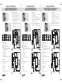
MANUAL DE INSTRUCCIONES
INSTRUCTIONS MANUAL
MANUEL D’INSTRUCTIONS
CUADROS PARA PROTECCIÓN Y CONTROL
DE BOMBAS SUMERGIBLES MONOFASICAS
PROTECTION AND CONTROL PANELS
FOR SINGLE-PHASE SUBMERSIBLE PUMPS
COFFRETS DE PROTECTION ET CONTRÔLE POUR
POMPES SUBMERSIBLES MONOPHASÉES
Esquema eléctrico / Conexionado
Connexion diagram
Schéma de connexions
Para evitar descargas eléctricas durante la instalación o manipulación
del cuadro, asegurarse de que no hay tensión en la línea
To prevent electrical shocks whilst installing or operating the relay,
disconnect the power supply.
Avant le montage et la mise en service, couper l’alimentation
secteur pour éviter toute décharge
1. Comprobar que la tensión de la línea es la correcta.
1. Check that the auxiliary voltage supply is correct.
1. Vérifier que la tension auxiliaire d’alimentation est la correct.
2. Para asegurar un buen funcionamiento del equipo y de la
instalación conectar el condensador con los μF especificados
por el fabricante de la motobomba. Sujetarlo con el soporte
autoadhesivo. Conectarlo en C y L1.
2. To ensure a correct functioning of the equipment, install the
capacitor with the μF recommended by the manufacturer of the
motor-pump. Set it using the auto-adhesive support. Connect
it to C and L1.
2. Installer le condensateur avec les μF spécifiés par le fabricant de
la moto-pompe, le soutenir avec le support autoadhésif et le
connecter en C et L 1.
3. Conectar los cables del motor en C, CL1 y L1.
3. Connect the wires of the motor to C, CL1 and L1.
4. Si no se necesita utilizar los terminales P1 y P2 para un presostato,
una boya, un temporizador, etc, estos terminales deberán estar
puenteados con un cable.
4. If terminals P1 and P2 are not going to be used for a pressure
switch, a buoy, a timer, etc., they must be bridged with a cable.
4. Si les terminales P1 et P2 ne vont pas être utilisés pour un
pressostat, une bouée, un temporisateur, etc., ils doivent être
pontés avec un câble.
5. Connect the power input to the terminals of the circuit breaker.
5. Connecter l’entrée du réseau dans les bornes du disjoncteur.
3. Connecter les câbles du moteur en C, CL1 et L1.
5. Conectar la entrada de la red en las bornas del magnetotérmico
11 a 16
2a3
1.5 a 2.2
Características principales
• Protecciones:
L
Trabajo en vacío controlando la subintensidad.
Sobrecarga con memoria térmica.
Sobretensión: si la tensión aumenta por encima del 15% de
la tensión nominal del relé, éste desconecta el motor. En el
momento en que la tensión vuelve a valores normales el relé
arranca el motor automáticamente.
Cortocircuito.
N
RELÉ PS11-R
KM
Iout
A1
A2
0.5 ... 2
0.37 ... 1.5
CBM-3
12314
11 ... 16
2 ... 3
1.5 ... 2.2
Main description
• Protections:
CONDENSADOR
ENTRADA RED
C
3 ... 11
CL1
L1
P1 P2
PRESOSTATO
SALIDA BOMBA
• Rearme remoto, o automático cada:
- PS11-R: 2 a 70 minutos.
- PS16-R: 2 a 240 minutos.
Dry running by undercurrent control.
Overload with thermal memory.
Overvoltage: if the voltage increases more than 15% over
the nominal voltage of the relay, it stops the motor. Once the
voltage returns to its normal value, the relay restarts the motor
automatically.
Short-circuit.
Iout
A1
CL1
L1
P1 P2
INPUT
PRESSURE
CONTACT
OUTPUT TO THE
PUMP
KM
• Relé electrónico Fanox PS
• Contactor
• Interruptor ON / OFF
L
N
RELÉ PS16-R
11
CONDENSADOR
14
A1 A2
INTERRUPTOR
• Circuit breaker 1P+N.
MAGNETOTÉRMICO
• Plastic case with transparent lid, 230 x 250 x 150 mm, IP 54
• Magnetotérmico 1P+N
• Connecting strip.
KM
CL1
L1
SALIDA BOMBA
P1 P2
• Auto-adhesive support for the capacitor.
CBM-3
12314
11 ... 16
2 ... 3
1.5 ... 2.2
Manque d’eau par sousintensité.
Surcharge avec mémoire thermique.
Surtension: si la tension augmente plus d’un 15% sur la
tension nominale du relais, ceci arrêt le moteur. Au moment
où la tension revient à des valeurs normales, le relais démarre
le moteur automatiquement.
Court-circuit.
RELAIS PS11-R
L
N
KM
Iout
A1
A2
CONDENSATEUR
ENTRÉE RÉSEAU
C
CL1
L1
P1 P2
SORTIE POMPE
PRESSOSTAT
Iin
KM
Composants
L
N
PS16-R RELAY
11
CAPACITOR
CONTACTEUR
• Relais électronique Fanox PS
• Contacteur
A1 A2
14
• Interrupteur arrêt/ marche
• Voyant de signalisation
Iout
POWER INPUT
• Réglette de connexions
KM
• 4 cable glands.
PRESOSTATO
0.37 ... 1.5
• Disjoncteur 1P+N
• Switch ON/OFF
• Signalling LED
0.5 ... 2
• Boîte en plastique avec couvercle transparent, 230 x 250 x 150 mm, IP54
• Contactor.
Iout
• 4 prensaestopas
C
KM
CONTACTOR
• Fanox PS electronic relay.
ENTRADA RED
3 ... 11
KM
• Indique la cause du déclenchement.
• Prise de contrôle pour pressostat, bouée, programmeur, etc.
Iin
Parts
• Caja de plástico con tapa transparente, 230 x 250 x 150 mm, IP54
12312
11
• Réarmement à distance ou automatique toutes les:
- PS11-R: 2 à 70 min.
- PS16-R: 2 à 240 min.
• Control point for pressure switch, buoy, programmer…
CONTACTOR
CBM-2
14
CONTACTEUR
• Protections:
POWER INPUT
C
IB (A)
Caractéristiques principales
A2
CAPACITOR
N
• Indicates cause of tripping.
Iin
Componentes
• Soporte autoadhesivo para el condensador
KM
- PS11-R: 2 to 70 min.
- PS16-R: 2 to 240 min.
• Toma de control para presostato, boya, programadores, etc.
• Regleta de conexiones
L
PS11-R RELAY
• Remote, or automatic reset every:
• Señaliza la causa de disparo.
• Piloto de señalización
CONTACTOR
Moteur 230 V 50/60 Hz
CV
kW
SWITCH
12314
12312
Modèles Code
KM
Plage de réglage
C
CL1
L1
OUTPUT TO THE
PUMP
RELAIS PS16-R
L
N
11
CONDENSATEUR
P1 P2
• Support autoadhésif pour le condensateur
A1 A2
Iout
ENTRÉE RÉSEAU
KM
• 4 presse-étoupe.
INPUT
PRESSURE
CONTACT
14
INTERRUPTEUR
CBM-3
CBM-2
Iin
11
DISJONCTEUR
0.37 a 1.5
IB (A)
14
MAGNÉTOTHERMIQUE
0.5 a 2
CONTACTOR
Code
Motor 230 V 50/60 Hz
HP
kW
SWITCH
3 a 11
Models
KM
Range
SWITCH
12312
Iin
11
CIRCUIT BREAKER
CBM-2
14
INTERRUPTOR
IB (A)
MAGNETOTÉRMICO
Modelos Código
Motor 230 V 50/60 Hz
CV
kW
CIRCUIT BREAKER
Iin
Rango
C
CL1
L1
SORTIE POMPE
P1 P2
PRESSOSTAT
Réglages à effectuer
Settings
En fonction des caractéristiques du moteur et de l’installation, il est
nécessaire d’effectuer quelques simples ajustements au relais PS.
S’assurer que le condensateur installé (μF) correspond avec celui
spécifié par le fabricant.
Signalisation :
: relais alimenté
: Déclenchement par surcharge/sousintensité
: Déclenchement par surtension
Depending on the characteristics of the motor and of the installation,
some simple adjustments must be made to the PS relay.
Check that the capacitor installed (μF) corresponds to the one
specified by the manufacturer.
L’ajustement du niveau de déclenchement par sous-charge se fait
par moyen d’un potentiomètre 2 . Avec ceci, un facteur entre 0,4
et 0,9 doit être sélectionné. En multipliant ce facteur par la IB
ajustée, nous obtenons une valeur d’intensité, en dessous de
laquelle, le relais déclenche et arrêt le moteur. Le déclenchement
est retardé 4 seconds.
Signalling:
ON
: relay in service
: Tripping by overvoltage
1
The setting of the underload trip level is made using a potentiometer
2 in which a factor between 0.4 and 0.9 is to be chosen. By
multiplying this factor by the adjusted IB, we obtain a current value
under which the relay will trip and disconnect the motor. The trip
is delayed 4 seconds.
Asegurarse de que el condensador instalado (μF) corresponde con
el especificado por el fabricante.
Señalización:
ON
: relé alimentado
: disparo por sobrecarga / subintensidad
4
3
2
3
3
1
2
IB = IN = 13A
IN
Réarmement
a) Après un déclenchement par surtension, le relais réarme
automatiquement quand la tension revient à ses paramètres
normaux.
b) Après un déclenchement par surcharge, le relais attend
approximativement 4 minutes avant de redémarrer la pompe
automatiquement.
(s)
e.g.
e.g.
IB = IN = 5A
IB = IN = 13A
Este ajuste se hace en base a la intensidad nominal del motor IN
indicada en su placa de características, el valor a ajustar IB es el
mismo que el de la intensidad nominal IN .
Ajustar el potenciómetro 1 con el valor de IB = IN
Reset
a) After a trip caused by overvoltage, the relay resets automatically
when the voltage returns to its normal value.
b) After a trip caused by overload, the relay waits for approximately
4 minutes before restarting the pump automatically.
c) After a trip caused by underload, the relay resets automatically
after the time adjusted by the potentiometer 3 .
IN
e.g.
e.g.
IB = IN = 5A
IB = IN = 13A
The relay trips with overloads above 1.1 x IB depending on the
curves class 10.
Afin de réarmer le relais de façon manuel, annuler l’alimentation
du coffret en débranchant son interrupteur magnétothermique,
par exemple, pendant 10 seconds approximativement et rétablir
l’alimentation après ce temps.
t
(s)
1000
Rearme
a) Después de un disparo por sobretensión el relé rearma
automáticamente cuando la tensión vuelve a tener valores
normales.
b) Después de un disparo por sobrecarga el relé espera
aproximadamente 4 minutos antes de volver a arrancar la bomba
automáticamente.
IN
c) Después de un disparo por subintensidad, el relé rearma
automáticamente cuando pase el tiempo ajustado mediante el
potenciómetro 3 .
- PS11-R: 2 to 70 min.
- PS16-R: 2 to 240 min. (by reset time factor 4 ).
- PS11-R: 2 à 70 min.
- PS16-R: 2 à 240 min. (moyen reset time factor 4 ).
1000
1 Ajuste de la intensidad IB “Full load current”
This adjustment is to be made according to the nominal current
of the motor IN indicated in its characteristics plate. The value to
be set IB is the same as IN .
Adjust the potentiometer 1 with the value IB = IN
c) Après un déclenchement par sousintensité, le relais réarme
automatiquement quand le temps ajusté (via potenciómètre
3 ) est écoulé.
Le relais déclenche par surcharge à partir de IB selon les courbes
clase 10
b) Si, debido a un excesivo sobredimensionado de la potencia del
motor, durante el funcionamiento se produjeran disparos
intempestivos, se reducirá el factor de ajuste por subcarga a
0,6.
1 Current setting IB “Full load current”
e.g.
IB = IN = 5A
2
b) If the power of the motor is excessively dimensioned and during
its functioning unwanted trips should occur, the underload
adjusted factor should be reduced to 0.6.
1 Réglage de l’intensité IB “Full load current”
e.g.
1
2
b) Si, pendant le fonctionnement, se produisent des déclenchements
intempestifs dus à un surdimensionnement excessif de la
puissance du moteur, l’ajustement du facteur de sous-charge
doit se réduire jusqu’à 0,6.
Ce réglage est effectué en base de l’intensité nominale du moteur
IN indiquée sur sa plaque de caractéristiques, la valeur à ajuster IB
est la même que celle de l’intensité nominale IN .
Ajuster le potentiomètre 1 avec la valeur IB = IN
4
3
2
3
1
El ajuste del nivel de disparo por subcarga se realiza por medio de
un potenciómetro 2 en el que se selecciona un factor entre 0,4
y 0,9. Multiplicando este factor por la IB ajustada nos da un valor
de intensidad por debajo del cual el relé disparará y desconectará
el motor. Este disparo está retardado 4 segundos.
1
4
3
2 Ajuste del nivel de disparo por subcarga
“undercurrent” x IB
a) Si la bomba está adecuadamente dimensionada, el valor
recomendado para este factor es 0,7.
Ajustar el potenciómetro 2 en 0,7.
Esto es aplicable a la mayoría de los casos
: disparo por sobretensión
1
2
t
En función de las características del motor y de la instalación hay
que realizar unos sencillos ajustes en el relé PS.
a) If the pump is adequately dimensioned, the recommended value
for this factor is 0.7
Adjust the potentiometer 2 at 0,7.
This is applicable for the majority of cases.
: Tripping due to overload/underload
a) Si la pompe est adéquatement dimensionnée, la valeur
recommandée pour ce facteur est de 0,7. Ajuster le potentiomètre
2 à 0,7.
Ceci est applicable dans presque la totalité des cas.
2 Setting of the underload trip level “undercurrent” x IB
In order to reset the relay manually, cancel the supply of the panel
for approximately 10 seconds, disconnecting the circuit breaker
and then, connect it again after this time has passed.
El relé dispara por sobrecarga a partir de 1,1 por IB según las curvas
de clase 10.
t
(s)
1000
- PS11-R: 2 a 70 minutos.
- PS16-R: 2 a 240 minutos (mediante el multiplicador 4 ) .
Para rearmar el relé de forma manual anular la alimentación del
cuadro durante 10 segundos aproximadamente, por ejemplo
desconectando su interruptor magnetotérmico, volviendo a
restablecer la alimentación pasado este tiempo.
100
100
100
Cold
10
Frío
10
Frío
10
Warm
1
1
2
3
4
Clase 10
5
6
7
6/2008
1
x IB
PAE ASUARAN, Edif. Artxanda, nave 23 - 48950 Asua - Erandio (Bizkaia) ESPAGNE
Tel. +34 94 471 14 09 - Fax. +34 94 471 05 92
E-mail : [email protected] - http://www.fanox.com
FANOX se réserve le droit de
modifier les caractéristiques
indiquées dans ce document
sans préavis.
1
2
3
4
Class 10
5
6
7
x IB
PAE ASUARAN, Edif. Artxanda, nave 23 - 48950 Asua - Erandio (Bizkaia) SPAIN
Tel. +34 94 471 14 09 - Fax. +34 94 471 05 92
E-mail : [email protected] - http://www.fanox.com
FANOX reserves the right to
modify
technical
specifications of products
contained within this
document without
previous notice.
1
1
2
3
4
Clase 10
5
6
7
6/2008
Caliente
Caliente
6/2008
ON
2 Réglage du niveau de déclenchement par sous-charge
“undercurrent” x IB
Ajustes a realizar
x IB
PAE ASUARAN, Edif. Artxanda, nave 23 - 48950 Asua - Erandio (Bizkaia) ESPAÑA
Tel. +34 94 471 14 09 - Fax. +34 94 471 05 92
E-mail : [email protected] - http://www.fanox.com
FANOX se reserva el derecho
de efectuar cualquier
modificación de las
características señaladas en
este documento sin
necesidad de previo aviso
MANUAL DE INSTRUCCIONES
INSTRUCTIONS MANUAL
MANUEL D’INSTRUCTIONS
CUADROS PARA PROTECCIÓN Y CONTROL
DE BOMBAS SUMERGIBLES MONOFASICAS
PROTECTION AND CONTROL PANELS
FOR SINGLE-PHASE SUBMERSIBLE PUMPS
COFFRETS DE PROTECTION ET CONTRÔLE POUR
POMPES SUBMERSIBLES MONOPHASÉES
Esquema eléctrico / Conexionado
Connexion diagram
Schéma de connexions
Para evitar descargas eléctricas durante la instalación o manipulación
del cuadro, asegurarse de que no hay tensión en la línea
To prevent electrical shocks whilst installing or operating the relay,
disconnect the power supply.
Avant le montage et la mise en service, couper l’alimentation
secteur pour éviter toute décharge
1. Comprobar que la tensión de la línea es la correcta.
1. Check that the auxiliary voltage supply is correct.
1. Vérifier que la tension auxiliaire d’alimentation est la correct.
2. Para asegurar un buen funcionamiento del equipo y de la
instalación conectar el condensador con los μF especificados
por el fabricante de la motobomba. Sujetarlo con el soporte
autoadhesivo. Conectarlo en C y L1.
2. To ensure a correct functioning of the equipment, install the
capacitor with the μF recommended by the manufacturer of the
motor-pump. Set it using the auto-adhesive support. Connect
it to C and L1.
2. Installer le condensateur avec les μF spécifiés par le fabricant de
la moto-pompe, le soutenir avec le support autoadhésif et le
connecter en C et L 1.
3. Conectar los cables del motor en C, CL1 y L1.
3. Connect the wires of the motor to C, CL1 and L1.
4. Si no se necesita utilizar los terminales P1 y P2 para un presostato,
una boya, un temporizador, etc, estos terminales deberán estar
puenteados con un cable.
4. If terminals P1 and P2 are not going to be used for a pressure
switch, a buoy, a timer, etc., they must be bridged with a cable.
4. Si les terminales P1 et P2 ne vont pas être utilisés pour un
pressostat, une bouée, un temporisateur, etc., ils doivent être
pontés avec un câble.
5. Connect the power input to the terminals of the circuit breaker.
5. Connecter l’entrée du réseau dans les bornes du disjoncteur.
3. Connecter les câbles du moteur en C, CL1 et L1.
5. Conectar la entrada de la red en las bornas del magnetotérmico
11 a 16
2a3
1.5 a 2.2
Características principales
• Protecciones:
L
Trabajo en vacío controlando la subintensidad.
Sobrecarga con memoria térmica.
Sobretensión: si la tensión aumenta por encima del 15% de
la tensión nominal del relé, éste desconecta el motor. En el
momento en que la tensión vuelve a valores normales el relé
arranca el motor automáticamente.
Cortocircuito.
N
RELÉ PS11-R
KM
Iout
A1
A2
0.5 ... 2
0.37 ... 1.5
CBM-3
12314
11 ... 16
2 ... 3
1.5 ... 2.2
Main description
• Protections:
CONDENSADOR
ENTRADA RED
C
3 ... 11
CL1
L1
P1 P2
PRESOSTATO
SALIDA BOMBA
• Rearme remoto, o automático cada:
- PS11-R: 2 a 70 minutos.
- PS16-R: 2 a 240 minutos.
Dry running by undercurrent control.
Overload with thermal memory.
Overvoltage: if the voltage increases more than 15% over
the nominal voltage of the relay, it stops the motor. Once the
voltage returns to its normal value, the relay restarts the motor
automatically.
Short-circuit.
Iout
A1
CL1
L1
P1 P2
INPUT
PRESSURE
CONTACT
OUTPUT TO THE
PUMP
KM
• Relé electrónico Fanox PS
• Contactor
• Interruptor ON / OFF
L
N
RELÉ PS16-R
11
CONDENSADOR
14
A1 A2
INTERRUPTOR
• Circuit breaker 1P+N.
MAGNETOTÉRMICO
• Plastic case with transparent lid, 230 x 250 x 150 mm, IP 54
• Magnetotérmico 1P+N
• Connecting strip.
KM
CL1
L1
SALIDA BOMBA
P1 P2
• Auto-adhesive support for the capacitor.
CBM-3
12314
11 ... 16
2 ... 3
1.5 ... 2.2
Manque d’eau par sousintensité.
Surcharge avec mémoire thermique.
Surtension: si la tension augmente plus d’un 15% sur la
tension nominale du relais, ceci arrêt le moteur. Au moment
où la tension revient à des valeurs normales, le relais démarre
le moteur automatiquement.
Court-circuit.
RELAIS PS11-R
L
N
KM
Iout
A1
A2
CONDENSATEUR
ENTRÉE RÉSEAU
C
CL1
L1
P1 P2
SORTIE POMPE
PRESSOSTAT
Iin
KM
Composants
L
N
PS16-R RELAY
11
CAPACITOR
CONTACTEUR
• Relais électronique Fanox PS
• Contacteur
A1 A2
14
• Interrupteur arrêt/ marche
• Voyant de signalisation
Iout
POWER INPUT
• Réglette de connexions
KM
• 4 cable glands.
PRESOSTATO
0.37 ... 1.5
• Disjoncteur 1P+N
• Switch ON/OFF
• Signalling LED
0.5 ... 2
• Boîte en plastique avec couvercle transparent, 230 x 250 x 150 mm, IP54
• Contactor.
Iout
• 4 prensaestopas
C
KM
CONTACTOR
• Fanox PS electronic relay.
ENTRADA RED
3 ... 11
KM
• Indique la cause du déclenchement.
• Prise de contrôle pour pressostat, bouée, programmeur, etc.
Iin
Parts
• Caja de plástico con tapa transparente, 230 x 250 x 150 mm, IP54
12312
11
• Réarmement à distance ou automatique toutes les:
- PS11-R: 2 à 70 min.
- PS16-R: 2 à 240 min.
• Control point for pressure switch, buoy, programmer…
CONTACTOR
CBM-2
14
CONTACTEUR
• Protections:
POWER INPUT
C
IB (A)
Caractéristiques principales
A2
CAPACITOR
N
• Indicates cause of tripping.
Iin
Componentes
• Soporte autoadhesivo para el condensador
KM
- PS11-R: 2 to 70 min.
- PS16-R: 2 to 240 min.
• Toma de control para presostato, boya, programadores, etc.
• Regleta de conexiones
L
PS11-R RELAY
• Remote, or automatic reset every:
• Señaliza la causa de disparo.
• Piloto de señalización
CONTACTOR
Moteur 230 V 50/60 Hz
CV
kW
SWITCH
12314
12312
Modèles Code
KM
Plage de réglage
C
CL1
L1
OUTPUT TO THE
PUMP
RELAIS PS16-R
L
N
11
CONDENSATEUR
P1 P2
• Support autoadhésif pour le condensateur
A1 A2
Iout
ENTRÉE RÉSEAU
KM
• 4 presse-étoupe.
INPUT
PRESSURE
CONTACT
14
INTERRUPTEUR
CBM-3
CBM-2
Iin
11
DISJONCTEUR
0.37 a 1.5
IB (A)
14
MAGNÉTOTHERMIQUE
0.5 a 2
CONTACTOR
Code
Motor 230 V 50/60 Hz
HP
kW
SWITCH
3 a 11
Models
KM
Range
SWITCH
12312
Iin
11
CIRCUIT BREAKER
CBM-2
14
INTERRUPTOR
IB (A)
MAGNETOTÉRMICO
Modelos Código
Motor 230 V 50/60 Hz
CV
kW
CIRCUIT BREAKER
Iin
Rango
C
CL1
L1
SORTIE POMPE
P1 P2
PRESSOSTAT
Réglages à effectuer
Settings
En fonction des caractéristiques du moteur et de l’installation, il est
nécessaire d’effectuer quelques simples ajustements au relais PS.
S’assurer que le condensateur installé (μF) correspond avec celui
spécifié par le fabricant.
Signalisation :
: relais alimenté
: Déclenchement par surcharge/sousintensité
: Déclenchement par surtension
Depending on the characteristics of the motor and of the installation,
some simple adjustments must be made to the PS relay.
Check that the capacitor installed (μF) corresponds to the one
specified by the manufacturer.
L’ajustement du niveau de déclenchement par sous-charge se fait
par moyen d’un potentiomètre 2 . Avec ceci, un facteur entre 0,4
et 0,9 doit être sélectionné. En multipliant ce facteur par la IB
ajustée, nous obtenons une valeur d’intensité, en dessous de
laquelle, le relais déclenche et arrêt le moteur. Le déclenchement
est retardé 4 seconds.
Signalling:
ON
: relay in service
: Tripping by overvoltage
1
The setting of the underload trip level is made using a potentiometer
2 in which a factor between 0.4 and 0.9 is to be chosen. By
multiplying this factor by the adjusted IB, we obtain a current value
under which the relay will trip and disconnect the motor. The trip
is delayed 4 seconds.
Asegurarse de que el condensador instalado (μF) corresponde con
el especificado por el fabricante.
Señalización:
ON
: relé alimentado
: disparo por sobrecarga / subintensidad
4
3
2
3
3
1
2
IB = IN = 13A
IN
Réarmement
a) Après un déclenchement par surtension, le relais réarme
automatiquement quand la tension revient à ses paramètres
normaux.
b) Après un déclenchement par surcharge, le relais attend
approximativement 4 minutes avant de redémarrer la pompe
automatiquement.
(s)
e.g.
e.g.
IB = IN = 5A
IB = IN = 13A
Este ajuste se hace en base a la intensidad nominal del motor IN
indicada en su placa de características, el valor a ajustar IB es el
mismo que el de la intensidad nominal IN .
Ajustar el potenciómetro 1 con el valor de IB = IN
Reset
a) After a trip caused by overvoltage, the relay resets automatically
when the voltage returns to its normal value.
b) After a trip caused by overload, the relay waits for approximately
4 minutes before restarting the pump automatically.
c) After a trip caused by underload, the relay resets automatically
after the time adjusted by the potentiometer 3 .
IN
e.g.
e.g.
IB = IN = 5A
IB = IN = 13A
The relay trips with overloads above 1.1 x IB depending on the
curves class 10.
Afin de réarmer le relais de façon manuel, annuler l’alimentation
du coffret en débranchant son interrupteur magnétothermique,
par exemple, pendant 10 seconds approximativement et rétablir
l’alimentation après ce temps.
t
(s)
1000
Rearme
a) Después de un disparo por sobretensión el relé rearma
automáticamente cuando la tensión vuelve a tener valores
normales.
b) Después de un disparo por sobrecarga el relé espera
aproximadamente 4 minutos antes de volver a arrancar la bomba
automáticamente.
IN
c) Después de un disparo por subintensidad, el relé rearma
automáticamente cuando pase el tiempo ajustado mediante el
potenciómetro 3 .
- PS11-R: 2 to 70 min.
- PS16-R: 2 to 240 min. (by reset time factor 4 ).
- PS11-R: 2 à 70 min.
- PS16-R: 2 à 240 min. (moyen reset time factor 4 ).
1000
1 Ajuste de la intensidad IB “Full load current”
This adjustment is to be made according to the nominal current
of the motor IN indicated in its characteristics plate. The value to
be set IB is the same as IN .
Adjust the potentiometer 1 with the value IB = IN
c) Après un déclenchement par sousintensité, le relais réarme
automatiquement quand le temps ajusté (via potenciómètre
3 ) est écoulé.
Le relais déclenche par surcharge à partir de IB selon les courbes
clase 10
b) Si, debido a un excesivo sobredimensionado de la potencia del
motor, durante el funcionamiento se produjeran disparos
intempestivos, se reducirá el factor de ajuste por subcarga a
0,6.
1 Current setting IB “Full load current”
e.g.
IB = IN = 5A
2
b) If the power of the motor is excessively dimensioned and during
its functioning unwanted trips should occur, the underload
adjusted factor should be reduced to 0.6.
1 Réglage de l’intensité IB “Full load current”
e.g.
1
2
b) Si, pendant le fonctionnement, se produisent des déclenchements
intempestifs dus à un surdimensionnement excessif de la
puissance du moteur, l’ajustement du facteur de sous-charge
doit se réduire jusqu’à 0,6.
Ce réglage est effectué en base de l’intensité nominale du moteur
IN indiquée sur sa plaque de caractéristiques, la valeur à ajuster IB
est la même que celle de l’intensité nominale IN .
Ajuster le potentiomètre 1 avec la valeur IB = IN
4
3
2
3
1
El ajuste del nivel de disparo por subcarga se realiza por medio de
un potenciómetro 2 en el que se selecciona un factor entre 0,4
y 0,9. Multiplicando este factor por la IB ajustada nos da un valor
de intensidad por debajo del cual el relé disparará y desconectará
el motor. Este disparo está retardado 4 segundos.
1
4
3
2 Ajuste del nivel de disparo por subcarga
“undercurrent” x IB
a) Si la bomba está adecuadamente dimensionada, el valor
recomendado para este factor es 0,7.
Ajustar el potenciómetro 2 en 0,7.
Esto es aplicable a la mayoría de los casos
: disparo por sobretensión
1
2
t
En función de las características del motor y de la instalación hay
que realizar unos sencillos ajustes en el relé PS.
a) If the pump is adequately dimensioned, the recommended value
for this factor is 0.7
Adjust the potentiometer 2 at 0,7.
This is applicable for the majority of cases.
: Tripping due to overload/underload
a) Si la pompe est adéquatement dimensionnée, la valeur
recommandée pour ce facteur est de 0,7. Ajuster le potentiomètre
2 à 0,7.
Ceci est applicable dans presque la totalité des cas.
2 Setting of the underload trip level “undercurrent” x IB
In order to reset the relay manually, cancel the supply of the panel
for approximately 10 seconds, disconnecting the circuit breaker
and then, connect it again after this time has passed.
El relé dispara por sobrecarga a partir de 1,1 por IB según las curvas
de clase 10.
t
(s)
1000
- PS11-R: 2 a 70 minutos.
- PS16-R: 2 a 240 minutos (mediante el multiplicador 4 ) .
Para rearmar el relé de forma manual anular la alimentación del
cuadro durante 10 segundos aproximadamente, por ejemplo
desconectando su interruptor magnetotérmico, volviendo a
restablecer la alimentación pasado este tiempo.
100
100
100
Cold
10
Frío
10
Frío
10
Warm
1
1
2
3
4
Clase 10
5
6
7
6/2008
1
x IB
PAE ASUARAN, Edif. Artxanda, nave 23 - 48950 Asua - Erandio (Bizkaia) ESPAGNE
Tel. +34 94 471 14 09 - Fax. +34 94 471 05 92
E-mail : [email protected] - http://www.fanox.com
FANOX se réserve le droit de
modifier les caractéristiques
indiquées dans ce document
sans préavis.
1
2
3
4
Class 10
5
6
7
x IB
PAE ASUARAN, Edif. Artxanda, nave 23 - 48950 Asua - Erandio (Bizkaia) SPAIN
Tel. +34 94 471 14 09 - Fax. +34 94 471 05 92
E-mail : [email protected] - http://www.fanox.com
FANOX reserves the right to
modify
technical
specifications of products
contained within this
document without
previous notice.
1
1
2
3
4
Clase 10
5
6
7
6/2008
Caliente
Caliente
6/2008
ON
2 Réglage du niveau de déclenchement par sous-charge
“undercurrent” x IB
Ajustes a realizar
x IB
PAE ASUARAN, Edif. Artxanda, nave 23 - 48950 Asua - Erandio (Bizkaia) ESPAÑA
Tel. +34 94 471 14 09 - Fax. +34 94 471 05 92
E-mail : [email protected] - http://www.fanox.com
FANOX se reserva el derecho
de efectuar cualquier
modificación de las
características señaladas en
este documento sin
necesidad de previo aviso