1
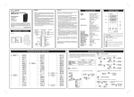
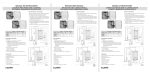
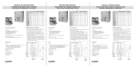
TEMPERATURE CONTROLLER
FANOX TP 720
Packaging content:
» PID Controller.
» Back cover.
» Brackets.
» Rubber outline.
» User manual.
Thank you for purchasing this product. We suggest to
read the user manual carefully before using the
equipment with the purpose of getting used to its
configuration and operating. Keep the manual for any
after-query.
www.fanox.com
WARNING
CAUTION
» Make sure to tight correctly the connection terminals.
If this is not done correctly mechanical failures or even
fire may occur.
» Please, do not install this equipment in locations where
inflammable gases can exist, due to the possibility of
explosion.
» The life-time of the equipment depends on the way
of use. If that life-time is exceeded, the probability of
deterioration of the equipment increases.
» Do not dismantle, review or repair the equipment by
your own without authorization. This can cause short
circuits on electrical parts, failures or fire.
» Do not introduce metallic elements between the chips
of the interior of the equipment or short circuits and
fire could be produced.
Please read the following warnings carefully, which will
allow you to use correctly the equipment:
4-20 mA output
0-10 V output
Relay output
DIMENSIONS / CUTOUT
4
3
4
3
OUT1
DC 4-20 mA
Voltage pulse
4
3
12 Vdc
Unit: mm
48
9
92
RS485
44,8
48
A
b
B
55
RTD
12
11
10
9
8
7
14
13
TC/mV
6
5
4
3
2
1
85-265 Vac
OUT1
ALM
14
13
OUT2
14
13
DC 4-20 mA
14
13
FRONTAL PANEL
Supply:
Display:
85~265 Vac, 50/60 Hz
Upper display (red):
4 digits 0,56” 7 segments
Lower display (green):
4 digits 0,36” 7 segments
Input signal:
Thermocouple:
J, K, B, N, R, S, T, E
RTD:
PT100, JPT100
Voltage DC:
0~350 mV
Output control:
Output relay (resistive)
SPDT, 5A/250 Vac
Output pulse voltage (SSR)
NPN, 20 mA at 12 Vdc
Analog output (max. 600_):
4~20 mA, 0~10 Vdc
Alarm relay:
SPST-NO, 3A/250 Vac (resis.)
Dwell time:
00~99 s
Hysteresis:
0~999,9 ºC (ºF)
Communications:
Output RS485
Operating conditions: 0~50 ºC (20~85 % HR)
Output control cycle: 0~999,9 s
Decimal point:
0~3 digits
Digital filter:
1~100
Control method:
ON/OFF or PID (Autotuning)
Offset input:
-199,9~999,9
Fraction value:
0000~9999
Setting range:
-1999~9999
Accuracy:
± 0,3 % ± 1 digit
Sampling time:
200 ms
Memory:
EEPROM
» Use the equipment within the specified limits for its
water immersion and exposure to oil.
» Do not use the equipment in locations exposed to
vibrations or thumps. The use of the equipment in
these locations can cause damages due to stress.
» Do not use the equipment in locations exposed to
dust, corrosive gases or direct sun.
» Separate the input signal devices, the cables of input
signal and the equipment from noise sources or high
voltage cables that generate noises.
» Separate the equipment from static electricity sources
when the equipment is used in areas where a lot of
static electricity is generated (e. g. manufacture of
compounds, dusts or transport of fluid material by
pipes).
» The organic solutions as well as basic or acid solutions
could damage the case of the temperature controller.
» Store it to the specified temperature. If the temperature
controller has been stored under – 10 ºC, keep the
equipment to room temperature during a minimum
of 3 hours before using it.
Please, verify the supply characteristics of the equipment.
Do not connect the terminals that are not going to be
used.
We propose the use of AWG 18 – 24 cables for the
signal line and AWG 25 – 30 cable for the supply and
exit contact relay.
OUT2
67
45
SPECIFICATIONS
12 Vdc
TP 720
PV
1
SV
2
3
OUT1
OUT2
OK
6
7
1
2
5
ALMI
8
4
Process value and function visualization: Red LED
of 7 segments.
Setting value and parameters visualization: Green
LED of 7 segments.
3
Indication of the output control.
4
Indication of alarms.
5
Indication of units.
6
key :
7
key :
8
key :
Back up to a superior level and add.
Advance to an inferior level and position.
OK
Move inside a level and confirm.
45
PROGRAM SETTING FLOWCHART
BUTTONS EXPLANATION
The settings of the equipment are controlled by means of 3 push-buttons
located in the front. First, you must decide which function you want to
enter and then use the push-buttons to reacht it. The push-buttons are
used in the following way:
BUTTON “FORWARD”
Allows to advance from a superior level to an inferior level.
SETTING
Selection
OK
OK
Settings
FORWARD
Advance to inferior level
Position
BACKWARD
Back up to a superior level
Add
OK
Move in a level
Confirm
SETTING
OK
SETTING
OK
OK
SETTING
BUTTON “OK”
1) Allows to move in a menu.
2) Confirm to save the settings.
It is also used to move between the positions of the digits of a value to
change.
1 2 3 4
1 2 3 4
1 2 3 4
1 2 3 4
OK
(Blinking)
(Blinking)
: Modify
OK
OK
OK
: Save
BUTTON “BACKWARD”
Allows to back up from a inferior level to a superior one:
It is also used to increase in a unit the
selected digit.
OK
OK
OK
1 2 3 4
1 2 3 4
(Blinking)
FUNCTION LIST
Ítem
Subitem
Range
-1999~9999
0000~9999
00~99
Default
0
0
00 s
-1999~9999
0
-1999~9999
-1999~9999
-1998~9999
-1999~9998
9999
0
9999
-1999
ºC
OFF
100
0
ON/OFF
OFF
0
0
3
200
20
0
1
000,0~1000
000,0~100,0
-1999~9999
-1999~9999
0000~9999
0000~9999
0000~9999
0000~9999
1~100
0000~9999
0000~9999
0000~9999
0000~9999
5s
5s
0000
0000
OFF
Ítem
Description
Alarm relay position 1
Alarm relay hysteresis 1
Alarm relay delay 1
Alarm relay direction 1
Alarm relay style 1
Alarm follow the action of Out 1
Alarm follow the action of Out 2
Set value SV
Decimal point set
Scale upper limit value
Scale lower limit value
Maximum range value SV
Minimum range value SV
Unit
Percentage
Scale input upper limit value
Scale input lower limit value
Operation
Autotuning
Input setting PV
SV offset value during autotuning
P value
I value
D value
Manual reset
Input digital filter
Hold temperature over room temperature
Hold temperature below room temperature
Heater is controlled by Out 1
Cooler is controlled by Out 1
Heater is controlled by Out 2
Cooler is controlled by Out 2
Control output direct / reverse operation 1
Control output direct / reverse operation 2
Cycle time 1 (seconds)
Cycle time 2 (seconds)
Control output hysteresis 1
Control output hysteresis 2
Deadband control
DESCRIPTION OF PARAMETERS
Subitem
Range
-1999~9999
-1999~9999
Default
0
0
0000~0255
0001
0100~9999
0100
Description
Deadband parameter of heater
Deadband parameter of cooler
Thermocouple type K (-200~1370 ºC)
Thermocouple type J (-210~1200 ºC)
Thermocouple type T (-200~400 ºC)
Thermocouple type E (-200~1000 ºC)
Thermocouple type R (-50~1760 ºC)
Thermocouple type S (-50~1760 ºC)
Thermocouple type B (250~1820 ºC)
Thermocouple type N (-200~1300 ºC)
Pt100 (-200~850 ºC)
JPT100 (-200~850 ºC)
DC Type (0~350 mV)
Device ID number
BaudRate : 600
BaudRate : 1200
BaudRate : 2400
BaudRate : 4800
BaudRate : 9600
BaudRate : 19200
BaudRate : 38400
8 byte size; no parity; 1 stop bit
8 byte size; no parity; 2 stop bit
8 byte size; odd parity; 1 stop bit
8 byte size; even parity; 1 stop bit
Hex
Ascii
Time Out / ms
Lock label 0
Lock label 1
Lock label 2
Lock label 3
0
0
0
0
0
0
0
0
0
0
0
0
0
0
0
0
0
0
0
0
0
0
0
0
0
0
0
0
0
In PID control, I=0, PV=SV, reset the control
output to the fixed value in this section.
Manual resetl
PV input filter
This function should be used when the
value of PV fluctuates widely, due to noises
in the input signal. If a longer constant time
is fixed, the filter eliminate more noises.
Control output
cycle time
The cycle time is the period of ON/OFF
repetitions of a relay or voltage pulse output
in the proportional PID control. The ratio
of the ON time to the cycle time is
proportional to the control output value.
Direction of relay.
Function list lock
You can set the mode of function lists which
can be displayed and edited.
TROUBLESHOOTING
Display over scale
Display under scale
PV over scale
PV under scale
Sensor break
: SV
HYSTERESIS
LOCK
0
A hysteresis can be adjusted around the
set point to prevent chattering.
ALARM MODE SETTING
FUNCTION LOCK
LOCK
Control output
hysteresis
: Alarm setting value
: Hysteresis setting value
Deviation high alarm
OFF
ON
Deviation high alarm
OFF
ON
LOCK
0
0
0
0
0
0
0
0
0
0
0
0
0
0
0
0
0
0
0
0
0
0
0
0
0
0
0
0
0
0
0
0
0
0
0
0
0
0
0
0
0
0
0
0
0
0
0
0
Heat.
X
X
X
0
SV+
SV
SV+
<0 ;
Deviation low alarm
ON
OFF
Deviation low alarm
ON
>0
OFF
Deviation high/low alarm
Heat.
X
0
0
0
0
FANOX ELECTRONIC
PAE. Asuaran, Edif. Artxanda, 23
48950 ERANDIO (Bizkaia) - SPAIN
Tel: +34 94 471 14 09 ; Fax: +34 94 471 05 92
www.fanox.com
Cool.
0
X
X
X
SV+
SV
SV+
>0 ;
Cool.
0
0
0
X
ON
OFF
ON
OFF
ON
OFF
Band alarm
<0
Process high alarm
OFF
X: (Disable): Inhibit output.
O: (Enable): Enable control output to
follow PID / ON-OFF control
algorithm.
ON
Process low alarm
ON
OFF