1
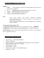
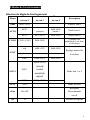
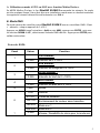
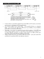
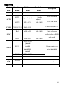
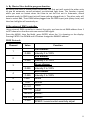
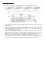
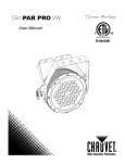
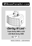
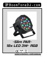
-Slim PAR18x LED 3W- RGB MODE D’EMPLOI – USER MANUAL 1 Français 1- Instructions de sécurité WARNING Avant d’utiliser votre matériel, nous vous recommandons de lire l’ensemble des instructions de ce manuel. Conservez ce manuel pour une future consultation. Si vous revendez cet appareil, veillez à transmettre également ce manuel d’utilisation au nouvel acquéreur. Déballez entièrement l’appareil ainsi que tous ses accessoires. Vérifiez qu’il n’y a aucun dommage et que l’appareil se trouve en parfait état. Il est important d’utiliser le câble d’alimentation secteur fourni (câble avec terre). Toujours débrancher l’appareil avant une intervention technique ou avant son entretien. Température ambiante maximum pour un fonctionnement optimal de l’appareil : 40°C. Ne pas utiliser l’appareil si la température ambiante dépasse cette valeur. En cas de problème de fonctionnement, arrêtez immédiatement l’appareil. Ne pas essayer de le réparer soi-même. Contactez votre revendeur ou faites appel à un réparateur spécialisé et agréé. Il n’y a aucune pièce remplaçable par l’utilisateur. Ne pas brancher cet appareil sur un bloc de puissance variable type “ Dimmer pack” Afin de réduire et d’éviter tout risque d’électrocution ou d’incendie, ne pas utiliser cet appareil dans un milieu humide ou sous la pluie. Ne pas regarder directement le faisceau lumineux. Cet appareil Slim PAR 18 RGB3 doit être installé avec un crochet solide et de dimension adéquate au poids supporté. L’appareil doit être vissé au crochet et serré convenablement afin d’éviter toute chute due aux vibrations produites par la machine en fonctionnement. L’accroche de l’appareil doit être sécurisée par une élingue de sécurité. Assurez-vous également que la structure (ou point d’accroche) peut supporter au moins 10X le poids de l’appareil accroché. L’appareil doit être installé par une personne qualifiée et doit être placé hors de portée du public. 2 2-Présentation du SlimPAR-18RGB3 Boutons : 1. MENU Pour accéder aux fonctions. Permet également de revenir en arrière dans la navigation. 2. UP Navigation dans les menus vers le haut (ou en avant) 3. DOWN Navigation dans les menus vers le bas 4. ENTER Pour la validation et accès au menu 5. Témoin lumineux de présence de signal Note: (1)Si aucun bouton n’est utilisé, l’afficheur s’éteindra automatiquement après 10 secondes. Appuyez sur n’importe quel bouton pour le réactiver. (2)Les paramètres sélectionnés sont automatiquement enregistrés après 2 secondes. 6. Connecteur d’alimentation “IN” 7. Connecteur d’alimentation “OUT” pour le repiquage d’un autre PARSLIM. 8. DMX input: Pour la connexion du câble DMX d’arrivée (type XLR 3 broches). 9. DMX output:Pour la connexion du câble DMX de sortie vers un autre appareil DMX (type XLR 3 broches). 3- Caractéristiques techniques Alimentation :AC100-240V 50/60Hz Fusible:F3A/250V Source lumineuse:18 x LED RGB 3 Watts (6 Rouges, 6 Vertes, 6 Bleues) Angle du faisceau lumineux : 45 degrés Consommation : 60W Canaux DMX:7 canaux Dimensions du carton:L230×W220×H85mm Poids brut:3.5 Kg 3 4-Modes de Fonctionnement Sélection du Mode de fonctionnement Menu Addr Menu Menu Menu niveau 2 niveau 3 niveau 4 A001~A512 SP-1~SP-9 St00~St99 (strobe) Mode Auto 1 AUT2 SP-1~SP-9 St00~St99 Mode Auto 2 CO01~CO51 St00~St99 red r000~r255 AUTO STAT Adresse DMX (vitesse) AUT1 COLO Description Couleur fixe prédéfinie (voir liste ci-dessous) St00~St99 Réglage manuel de Gree G000~G255 St00~St99 blue b000~b255 St00~St99 la couleur SEN0~SEN9 (sound SOUN SOU1 control sensitivity Mode Son 1 et 2 adjust) SOU2 SLAV SLA SEN0~SEN9 Mode Esclave Récepteur rEno On~oFF télécommande on/off Ver 10 Version du logiciel 4 A. Utilisation en mode AUTO ou SON avec fonction Maître/Esclave. En MODE Maître /Esclave, le 1er SlimPAR 18 RGB 3 commande les suivants. Ce mode est très pratique lorsqu’il vous faut faire une installation rapide avec un résultat immédiat. Les appareils suivants doivent être sélectionnés en « SLA ». B. Mode DMX Ce mode permet de contrôler votre SlimPAR 18 RGB 3 avec un contrôleur DMX. Il faut « adresser » chaque appareil de 1 à 512. Appuyez sur MENU jusqu’à visualiser « Addr » puis A001, appuyez sur ENTER , puis avec les touches DOWN et UP , sélectionnez l’adresse DMX désirée . Appuyez sur ENTER pour valider cette valeur Protocole DMX: Canal Valeur Full Dimmer : 1 0-255 0-255 0-255 7 Intensité du Vert de 0 à 100% Blue dimmer 0-255 1-255 0-50 6 Intensité du Rouge de 0 à 100% Green dimmer : 3 5 Intensité de 0 à 100% Red dimmer : 2 4 Fonction Intensité du Bleu de 0 à 100% Strobe Dimmer 51-101 Fondu de couleurs 102-152 Enchainement de couleur sans transition 153-203 Mode son 1 204-255 Mode son 2 0-255 Vitesse / Sensibilité du micro pour le mode son 5 5. Mode DMX (Connexion DMX) Si vous utilisez un contrôleur équipé d’une sortie DMX en XLR 5 points, vous devez vous procurer un adaptateur XLR 5 points/3 points. Sur le dernier appareil de la chaine DMX, il est conseillé d’utiliser un « bouchon DMX ». (une résistance de 120 Ohms 1/4W entre le pin 2(DMX-) et le pin 3(DMX+) placée dans un connecteur DMX mâle). Connectez “ à la chaine” les appareils les uns après les autres : Sortie DMX vers Entrée DMX de l’appareil suivant. Le câble DMX ne doit JAMAIS être un câble en “Y”. La liaison DMX-512 transporte un signal à haute vitesse. Les câbles utilisés pour cette liaison doivent être de bonne qualité et en bon état. Chaque appareil doit avoir une adresse DMX bien précise pour qu’il puisse être contrôlé par le contrôleur DMX. (voir tableau ci-dessus ). 6 6- Dépannage Voici quelques suggestions si vous rencontrez des problèmes avec votre appareil SlimPAR 18 RGB 3. L’appareil ne fonctionne pas du tout. o Vérifiez le cordon d’alimentation et le fusible. o Assurez-vous que votre prise soit bien alimentée. L’appareil ne répond pas ou pas correctement aux commandes DMX. o Vérifiez vos câbles DMX o Vérifiez votre adressage DMX o Essayez un autre contrôleur DMX o Vérifiez que vos câbles DMX ne passent pas à proximité de câbles haute tension, ce qui pourrait créer des interférences. Ne réagit pas au son o Vérifiez le mode de fonctionnement choisi o Vérifiez qu’il n’y a pas de câble DMX branché sur DMX IN o Tapotez directement sur le microphone pour tester sa réactivité. 7- Entretien Un nettoyage extérieur de l’appareil doit être fait régulièrement. Les lentilles doivent être nettoyées pour une luminosité optimum. Si l’appareil est installé dans un environnement poussiéreux ou avec de la fumée cet entretien régulier est très important. Il est possible qu’un nettoyage des optiques par l’intérieur soit également nécessaire. Débranchez l’appareil avant toute intervention ! Utilisez un chiffon propre avec très peu de liquide vitre. Toujours bien sécher les parties nettoyées. 7 English 1- Safety Instructions WARNING Please read the instructions carefully which includes important information about the installation, operation and maintenance. Please keep this User Manual for future consultation. If you sell the fixture to another user, be sure that they also receive this instruction booklet. Unpack and check carefully there is no transportation damage before using the fixture. It’s important to ground the yellow/green conductor to earth in order to avoid electric shock. Disconnect main power before servicing and maintenance. Maximum ambient temperature is Ta : 40°. Don’t operate it where the temperature is higher than this. In the event of serious operating problem, stop using the fixture immediately. Never try to repair the fixture by yourself. Repairs carried out by unskilled people can lead to damage or malfunction. Please contact the nearest authorized technical assistance center. There are no user serviceable parts inside the fixture. Do not connect the device to any dimmer pack. To prevent or reduce the risk of electrical shock or fire, do not expose the fixture to rain or moisture. Do not look directly at the LED light beam while the fixture is on. Do not touch any wire during operation. The unit should be mounted via its screw holes on the bracket. Always ensure that the unit is firmly fixed to avoid vibration and slipping while operating. Always ensure that the structure to which you are attaching the unit is secure and is able to support a weight of 10 times of the unit’s weight. Also always use a safety cable that can hold 12 times of the weight of the unit when installing the fixture. The equipment must be fixed by professionals. And it must be fixed at a place where is out of the touch of people and has no one pass by or under it. 8 2- Unit Description Buttons: 1. MENU To go forward in the selected functions or go back the last layer menu 2. UP To go forward in the selected functions or increase parameters 3. DOWN To go backward in the selected functions or reduce parameters 4. ENTER To go into the next layer menu 5. Signal indicator light In DMX or SLAVE mode, the Signal indicator light flashing when signals are detected 6. Mains input:Connect to supply mains power. 7.Mains output:Connect to supply mains power for the next unit. 8. DMX input: For DMX512 link, use 3-pin XLR plug cable to input DMX signal. 9. DMX output:For DMX512 link, use 3-pin XLR plug cable to link the next unit. Note: (1)In ten seconds, if no buttons to press, the LED display will be off. Press any button to turn the display on again. (2)After pressing a button, all the parameters will save automatically after 2 seconds. (3)No matter the item is in which program in which mode, once detecting DMX or SLAVE signal, the program will jump into DMX or SLAVE mode automatically. Then,if DMX/SLAVE signal off, the program will return to the original mode . 3 Technical Specifications Power supply:AC100-240V 50/60Hz Fuse:F3A/250V Power Supply:IEC Input/output block Light source:18 x 3 Watt RGB (6 Red, 6 Green, 6 Blue) Beam Angle: 45 degrees Channel:7 DMX channels Packing Dimensions :L230×W220×H85mm Gross Weight:3.5 kg 9 4- Menu Main Secondary Third-level Fourth-level menu menu menu menu Addr A001~A512 AUT1 DMX address SP-1~SP-9 (speed adjust) AUTO COLO STAT Description St00~St99 (strobe adjust) AUT2 SP-1~SP-9 St00~St99 CO01~CO51 St00~St99 Red r000~r255 St00~St99 Gree G000~G255 St00~St99 Blue b000~b255 St00~St99 FADE run mode JUMP run mode Fixed color,have 51 colors Static color.can adjust value of RGB and strobe SEN0~SEN9 (sound SOUN SOU1 control Sound control,can sensitivity adjust sensitivit adjust) SOU2 SLAV SLA rEno On~oFF Ver 10 SEN0~SEN9 Slave mode IR remote control switch version NO. 10 A. By Master/Slave built-in program function. By linking the units in master/slave connection, the first unit will control the other units to give an automatic, sound activated, synchronized light show. This function is good when you want an instant show. You have to set the first unit in Automatic, sound activated mode. Its DMX input jack will have nothing plugged into it. The other units will have to select SLA , Their DMX cables plugged into the DMX input jacks (daisy chain) and the slave led lights will constantly on. B. By universal DMX controller Using universal DMX controller to control the units, you have to set DMX address from 1 to 512 channel so that the units can receive DMX signal. Press the MENU, then find Addr ,press ENTER, when the 1 is showing on the display. Pressing ENTER. Use DOWN and UP button change the DMX512 address. DMX Protocol : Channel Value Full Dimmer : 1 0-255 0-255 0-255 7 Intensity 0 to 100% Blue dimmer 0-255 1-255 0-50 6 Intensity 0 to 100% Green dimmer : 3 5 Intensity 0 to 100% Red dimmer : 2 4 Function Intensity 0 to 100% strobe dimmer 51-101 FADE 102-152 JUMP 153-203 Sound1 204-255 Sound2 0-255 SPEED / sound control sensitivity adjust 11 5. DMX 512 Connection The DMX 512 is widely used in intelligent lightings and with a maximum of 512 channels. 1. 2. 3. 4. If you using a controller with 5 pins DMX output, you need to use a 5 to 3 pin adapter-cable. At last unit, the DMX cable has to be terminated with a terminator. Solder a 120 ohm 1/4W resistor between pin 2(DMX-) and pin 3(DMX+) into a 3-pin XLR-plug and plug it in the DMX-output of the last unit. Connect the unit together in a ‘daisy chain’ by XLR plug from the output of the unit to the input of the next unit. The cable cannot be branched or split to a ‘Y’ cable. DMX512 is a very high-speed signal. Inadequate or damaged cables, solder joints or corroded connectors can easily distort the signal and shut down the system. Each lighting unit needs to have an address set to receive the data sent by the controller. The address number is between 0-511 (usually 0 & 1 are equal to 1). 12 6. Troubleshooting Following are a few common problems that may occur during operation. Here are some suggestions for easy troubleshooting: The fixture does not work, no light o Check the connection of power and main fuse. o Measure the mains voltage on the main connector. Not responding to DMX controller o DMX LED should be on. If not, check DMX connectors, cables to see if link properly. o If the DMX LED is on and no response to the channel, check the address settings and DMX polarity. o If you have intermittent DMX signal problems, check the pins on connectors or on PCB of the fixture or the previous one. o Try to use another DMX controller. o Check if the DMX cables run near or run alongside to high voltage cables that may cause damage or interference to DMX interface circuit. Some fixtures don’t respond to the easy controller o You may have a break in the DMX cabling. o Check the LED for the response of the master/ slave mode signal. No response to the sound o Make sure the fixture does not receive DMX signal. o Check microphone to see if it is good by tapping the microphone. 6. Fixture Cleaning The cleaning of internal must be carried out periodically to optimize light output. Cleaning frequency depends on the environment in which the fixture operates: damp, smoky or particularly dirty surrounding can cause greater accumulation of dirt on the fixture’s optics. Clean with soft cloth using normal glass cleaning fluid. Always dry the parts carefully. Clean the external optics at least every 20 days. Clean the internal optics at least every 30/60 days 13 14