1
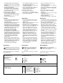
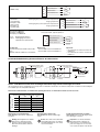
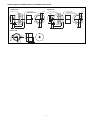
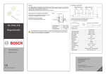
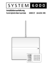
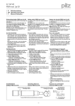
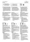
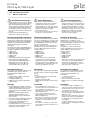
20 915-06
PSEN 2.2p-20, PSEN 2.2p-21
4
4
4
D
Betriebsanleitung
GB Operating instructions
F
Manuel d'utilisation
Sicherheitsbestimmungen
Safety Regulations
Conseils préliminaires
• Das Gerät darf nur von Personen installiert
und in Betrieb genommen werden, die mit
dieser Betriebsanleitung und den geltenden Vorschriften über Arbeitssicherheit und
Unfallverhütung vertraut sind. Beachten
Sie die VDE- sowie die örtlichen Vorschriften, insbesondere hinsichtlich Schutzmaßnahmen.
• Entfernen Sie die Schutzkappe erst
unmittelbar vor Anschluss des Geräts
• The unit may only be installed and
operated by personnel who are familiar
with both these instructions and the
current regulations for safety at work and
accident prevention. Follow VDE and local
regulations especially as regards
preventative measures.
• Do not remove the protective cap until you
are about to connect the device.
• La mise en oeuvre de l'appareil doit être
effectuée par une personne spécialisée en
installations électriques, en tenant compte
des prescriptions des différentes normes
applicables (NF, EN, VDE..), notamment
au niveau des risques encourus en cas de
défaillance de l'équipement électrique.
• Veuillez retirer le cache de protection
avant de raccorder l’appareil.
Bestimmungsgemäße Verwendung
Authorized applications
Domaines d'utilisation
Die Sicherheitsschalter PSEN 2.2p-20 und
PSEN 2.2p-21 sind bestimmt für den Einsatz
in Sicherheitsstromkreisen nach EN 60204-1
(VDE 0113-1) und IEC 60204-1 (Stellungsüberwachung beweglicher Schutzeinrichtungen).
Der Sicherheitsschalter erfüllt EN 60947-5-3
nur zusammen mit dem Betätiger PSEN 2.220 und den folgenden Auswertegeräten:
• PNOZ e3.1p
• PNOZ e3vp 10s
• PNOZ e3vp 300s
• PNOZ e5.13p
• PNOZmulti
• Sicherheitssteuerung der Systemfamilie
PSS zusammen mit dem Standardfunktionsbaustein SB066 (MBS-Pakete
Exzenterpressen, Best.-Nr. 301 172;
Hydraulikpressen, Best.-Nr. 301 173;
Transferstraßen, Best.-Nr. 301 175)
The safety switch PSEN 2.2p-20 and PSEN
2.2p-21 are intended for use in safety circuits
in accordance with EN 60204-1 (VDE 01131) and IEC 60204-1 (position monitoring of
moveable safety devices).
The safety switch meets the requirements of
EN 60947-5-3 only in conjunction with the
actuator PSEN 2.2-20 and the following
evaluation devices:
• PNOZ e3.1p
• PNOZ e3vp 10s
• PNOZ e3vp 300s
• PNOZ e5.13p
• PNOZmulti
• Safety control system from the PSS
system range in conjunction with the
standard function block SB066 (MBS
packages Eccentric Press, Order No. 301
172; Hydraulic Press, Order No. 301 173;
Transfer Line, Order No. 301 175)
Les capteurs de sécurité PSEN 2.2p-20 et
PSEN 2.2p-21 sont adaptés pour une
utilisation dans les circuits de sécurité selon
les normes EN 60204-1 (VDE 0113-1) et IEC
60204-1 (Surveillance de protecteurs
mobiles).
Le capteur de sécurité ne répond aux
exigences EN 60947-5-3 qu'en liaison avec
l'aimant PSEN 2.2-20 et les unités de
contrôles suivantes :
• PNOZ e3.1p
• PNOZ e3vp 10s
• PNOZ e3vp 300s
• PNOZ e5.13p
• PNOZmulti
• Automates de sécurité de la gamme PSS
avec le bloc fonction standard SB066
(Progiciel Presse Excentrique, réf. 301
172; Presses hydrauliques, réf. 301 173;
Ligne de transfert , réf.301 175)
Gerätebeschreibung
Description
Description de l'appareil
Zu den Sicherheitsschaltern PSEN 2.2p-20
und PSEN 2.2p-21 gehört jeweils der
Betätiger (Magnet) PSEN 2.2-20.
Merkmale:
• 2 Reedkontakte (1 Öffner/1 Schließer)
• Wirkweise magnetisch
• Schaltspannung 30 V DC
• PSEN 2.2p-21: mit LED zur Anzeige des
Schaltzustands
The safety switch PSEN 2.2p-20 and PSEN
2.2p-21 include the actuator (magnet) PSEN
2.2-20.
Features:
• 2 reed contacts (1 N/C / 1 N/O contact)
• Magnetic operation
• Switching voltage 30 V DC
• PSEN 2.2p-21: with LED for switch status
display
Les capteurs de sécurité PSEN 2.2p-20 et
PSEN 2.2p-21 sont utilisés en liaison avec
l'actionneur (aimant) PSEN 2.1-10.
Particularités :
• 2 contacts reed (1 O/1F)
• Action magnétique
• Tension de commutation 30 V DC
• PSEN 2.2p-21 : avec LED pour affichage
status
Montage
Installation
Installation
• Die Montagelage ist beliebig. Sicherheitsschalter und Betätiger müssen so montiert
werden, dass die beiden Kerben genau
gegenüberliegen (siehe Abbildung "Schaltabstände").
• Eine Nase auf dem Betätiger dient als
Sicherung gegen Verdrehen (siehe
Abbildung "Abmessungen"). Bohrdurchmesser: 2 mm.
• Sicherheitsschalter und Betätiger möglichst
nicht auf ferromagnetisches Material
montieren. Es sind Änderungen der
Schaltabstände zu erwarten.
• Der Abstand zwischen zwei Systemen aus
Sicherheitsschalter und Betätiger muss
mindestens 25 mm betragen.
• The mounting position can be freely
selected. Safety sensor and actuator have
to be installed in a way that the two
indentations are exactly opposite (see Fig.
"Switching distances").
• A nose on the actuator is to secure it
against twisting (see Fig. "Dimensions").
Diameter drilled: 2 mm.
• If possible, do not install the safety switch
and actuator on ferromagnetic material.
Changes of the switch offsets are to be
anticipated.
• Two systems consisting of a safety sensor
and a actuator must have a distance of at
least 25 mm.
• Le sens de montage est indifférent. Le
capteur de sécurité et l'aimant doivent être
montés de telle façon que leur encoches
soient exactement face à face.
• Un détrompeur sur l'actionneur garantie le
sens de montage (voir fig. "Dimensions").
diamètre : 2 mm.
• Si possible, évitez d'installer le capteur et
l'aimant sur du matériel ferromagnétique.
Les distances de commutation peuvent
être modifiées.
• La distance minimale entre 2 systèmes
complets( capteur et aimant) doit être d'au
moins 25 mm.
-1-
• Zwei Muttern M30 zur Befestigung des
Sicherheitsschalter sind im Lieferumfang
enthalten.
• Das Anzugsdrehmoment der Mutter M30
beträgt maximal 300 Ncm.
• Befestigen Sie den Betätiger mit einer
Schraube M4 oder M5. Verwenden Sie
eine Schraube aus nicht-magnetischem
Material (z. B. Messing).
Sicherheitsschalter und Betätiger
• von Eisenspänen fernhalten
• keinen starken Magnetfeldern aussetzen
• keinen starken Stößen oder Schwingungen aussetzen
• nicht als Anschlag benutzen
• Two nuts M30 for fixing the safety sensor
are included in the package.
• The torque setting of the nut M30 may be
a maximum of 300 Ncm.
• Fix the actuator with an M4 or M5 screw.
Use a screw that is made from nonmagnetic material (e.g. brass).
Safety switch and actuator:
• keep away from iron cuttings
• do not expose to strong magnetic fields
• do not expose to strong shocks or vibration
• do not use as dead stop
• Deux écrous M30 sont livrés avec le
capteur pour sa fixation.
• Le couple de serrage des écrous M30 est
au max. de 300 Ncm.
• Fixer l'aimant à l'aide d'une vis M4 ou M5.
Utiliser une vis en métal non magnétiques
(par ex. laiton).
Le capteur de sécurité et l'actionneur :
• doivent être éloignés des copeaux
métalliques
• ne doivent pas être exposés à des champs
magnétiques élevés
• ne doivent pas subir des chocs et
vibrations importants
• ne doivent pas être utilisés comme butée
Justage
Adjustment
Ajustement
• Der Sicherheitsschalter darf nur mit dem
zugehörigen Betätiger PSEN 2.2-20
verwendet werden.
• Prüfen Sie die Funktion immer mit einem
der zugelassenen Auswertegeräte.
• Beim PSEN 2.2p-21 leuchtet die LED bei
unbetätigten Reedkontakten (Schutzeinrichtung geöffnet oder Sicherheitsschalter
und Betätiger falsch justiert). Die LED
befindet sich im Öffnerkreis des
Sicherheitsschalter. Bei betätigten
Reedkontakten erlischt die LED.
• Die angegebenen Schaltabstände (siehe
technische Daten) gelten nur, wenn die
beiden Kerben am Sicherheitsschalter und
Betätiger gegenüberliegend ausgerichtet
montiert sind. Andere Anordnungen
können zu abweichenden Schaltabständen führen.
• Beachten Sie den maximal zulässigen
Seiten- und Höhenversatz (siehe "Schaltabstände" und "Max. Seiten- und Höhenversatz"). Die Werte gelten nur bei nach
oben ausgerichteten Kerben von
Sicherheitsschalter und Betätiger.
• The safety switch must only be used in
conjunction with its respective actuator
PSEN 2.2-20.
• Always check the functions with one of the
approved evaluation devices.
• On PSEN 2.2p-21 the LED lights when
the reed contacts are not operated (safety
device is open or safety switch and
actuator are adjusted incorrectly). The
LED is in the N/C contact circuit of the
safety sensor. When the reed contacts
are operated, the LED will go out.
• The stated switch offsets (see technical
data) are only valid, when the two
indentations at the safety sensor and
actuator are mounted so that they are
aligned opposite each other. Different
layouts may lead to deviating switching
gaps.
• Please note the maximum permissible
lateral and height offset (see "Switching
distances" and "Max. lateral and height
offset"). These values are only valid for
top-aligned indentations of the safety
sensor and actuator.
• Le capteur de sécurité ne peut être utilisé
qu'avec l'actionneur (aimant) PSEN 2.2-20.
• Testez la fonction uniquement avec une
des unités de contrôle autorisées.
• Sur le PSEN 2.2p-21, la LED est allumée
quand les contacts reed ne sont pas
actionnés (protecteur ouvert ou mauvais
alignement du capteur et de l'actionneur).
La LED est insérée dans le contact à
ouverture du capteur de sécurité. Quand
les contacts Reed sont actionnés, la LED
s'éteint.
• Les distances de commutation indiquées
(voir caractéristiques techniques) ne sont
valables que si, lors du montage, les
encoches du capteur et de l'aimant sont
face à face. Un autre montage peut
entraîner la modfication des distances de
commutation.
• Veuillez noter les valeurs des décalages
latéraux et en hauteur toléréés (voir
"Distances de commutation" et "décalage
latéral max. et décalage en hauteur
max."). Les valeurs ne sont valables que
pour un montage avec les encoches vers
le haut du capteur et de l'aimant.
Anschlüsse
Connections
Raccordement
Notice: The colour marking of the
connection cables only applies to
cables available from Pilz as an
accessory.
Wichtig: Die Farbkennzeichnung für
die Anschlussleitung gilt nur für die als
Zubehör erhältlichen Kabel von Pilz
Der Sicherheitsschalter ist in unbetätigtem
Zustand dargestellt
Belegung des
4pol. M8-Stiftsteckers/
Configuration of the 4pin M8 connector/
Repérage du
connecteur M8 4 br.
Anschluss an Auswertegerät
• PNOZ e3.1p
• PNOZ e3vp 10s
• PNOZ e3vp 300s
1
3
2
4
Important : Les repérages des
couleurs ne sont valables que pour les
câbles fournis par Pilz.
The safety switch is shown in not operated
mode.
Le capteur de sécurité est représenté en
position non actionnée.
PSEN 2.2p-20
ohne/without/sans LED
PSEN 2.2p-21
mit/with/avec LED
1
1
2
2
3
3+
4
4
Connection to evaluation device
Raccordement à l'unité de contrôle
S11
S12
S23
S24
braun/brown/marron 1
weiß/white/blanc
2
blau/blue/bleu
3
schwarz/black/noir
4
-2-
A1
S32
• PNOZ e5.13p
A1
S44
• Beispiel für
Sicherheitssteuerung PSS
• Example of PSS
safety system
• Exemple pour
automate PSS
braun/brown/marron 1
weiß/white/blanc
2
blau/blue/bleu
3
schwarz/black/noir
4
Taktausgang/Test pulse output/Sortie impulsionnelle
O 16
Eingang/Input/Entrée
I 00
Taktausgang/Test pulse output/Sortie impulsionnelle
O 17
Eingang/Input/Entrée
I 01
braun/brown/marron 1
weiß/white/blanc
2
blau/blue/bleu
3
schwarz/black/noir
4
Schutztür, Schaltertyp 2/Safety gate, switch type 2/
Protecteur mobile, type du capteure 2
• Beispiel für PNOZmulti
• Example of PNOZmulti
• Exemple pour PNOZmulti
T0
I0, I1: Eingänge/Inputs/Entrées
T0, T1: Taktausgänge/Test pulse
outputs/Sorties impulsionnelle
I0
T1
I1
Beachten Sie:
• Schließerkontakt des PSEN an I0 anschließen
• Öffnerkontakt des PSEN an I1 anschließen
braun/brown/marron 1
weiß/white/blanc
2
blau/blue/bleu
3
schwarz/black/noir
4
Please note:
• Connect N/O contact from PSEN to I0
• Connect N/C contact from PSEN to I1
Important :
• raccordement du contact à fermeture du
PSEN à I0
• raccordement du contact à ouverture du
PSEN à I1
Schaltabstände/Switching distances/Distance de commutation
Seitenversatz/Lateral offset/
Décalage latéral sar = 26
sao = 8
somin = 0,5
aktive Fläche
active area
surface active
Höhenversatz/Height offset/
Décalage en hauteur
Kerbe
Indentation
Enchose
Ein/On/Marche
Aus/Off/Arrêt
Seiten- und Höhenversatz/Lateral and height offset/Décalage latéral et Décalage en hauteur
(Die angegebenen Werte sind gültig bei einer Temperatur von 20°C/The stated values are valid at a temperature of 20°C/Les valeurs indiquées
sont valables pour une température de 20°C.)
Seitenversatz/Lateral offset/
Décalage latéral
Gesicherter Schaltabstand Sao in mm/Assured operating distance Sao in mm/Portée de travail assurée Sao en mm
Höhenversatz/Height offset/Décalage en hauteur
0,5
1,0
1,0
7,5
7,5
2,0
7,0
7,0
3,0
6,5
6,5
4,0
6,0
6,0
5,0
5,0
5,0
6,0
4,5
4,5
Gesicherter Ausschaltabstand Sar :
max. 26 mm bei allen Höhen- und Seitenversätzen
Wichtig: Die Angaben in der Tabelle
"Max. Seiten- und Höhenversatz"
gelten bei oben liegenden Kerben
beim Sicherheitsschalter und beim
Betätiger.
Assured release distance Sar :
max. 26 mm with all lateral and height
offsets
Notice: The entries in the table "Max.
lateral and height offset" are valid for
top-aligned indentations of the safety
sensor and actuator.
-3-
Portée de déclenchement assurée Sar :
max. 26 mm pour tous les décalages latéral
et les décalages en hauteur
Important : les valeurs du tableau
"Décalage latéral et décalage en
hauteur max" ne sont valables que
pour un montage avec les encoches
vers le haut du capteur et de l'aimant.
Technische Daten
Technical Data
Caractéristiques techniques
Technische Daten
Hysterese typ.
PSEN 2.2-20
Schaltabstände
Gesicherter Schaltabstand sa
Min. Schaltabstand somin
Gesicherter Ausschaltabstand sar
Schaltspannung
Innenwiderstand
Max. Schaltstrom Sicherheitskontakte
Max. Schaltleistung Sicherheitskontakte
Max. Schaltfrequenz
Betätiger
Umgebungstemperatur
Schwingungen nach EN 60947-5-2
Frequenz
Amplitude
EMV
Schockbeanspruchung
Verschmutzungsgrad
Bemessungsisolationsspannung
Bemessungsstoßspannungsfestigkeit
Anschlussart
Technical data
Hysteresis typ.
PSEN 2.2-20
Switching distances
Assured operating distance sao
Min. operating distance somin
Assured release distance sar
Switching voltage
Internal resistance
Max. switching current for safety
contacts
Max. breaking capacity for safety
contacts
Max. switching frequency
Actuator
Ambient temperature
Vibration to EN 60947-5-2
Frequency
Amplitude
EMC
Shock stress
Pollution degree
Rated insulation voltage
Rated impulse withstand voltage
Connection type
Caractéristiques techniques
Hystérésis env.
PSEN 2.2-20
Distances de commutation
Portée de travail assurée sao
Portée de travail min. somin
Portée de déclenchement assurée sar
Tension de commutation
Résistance interne
Courant max. de commutation des
contacts de sécurité
Puissance max. de commutation des
contacts de sécurité
Fréquence de commutation max.
Actionneur
Température ambiante
Vibrations selon EN 60947-5-2
Fréquence
Amplitude
CEM
Résistance aux chocs
Niveau d'encrassement
Tension assignée d'isolement
Tension assignée de tenue aux
chocs
Type de connection
Leitung
Schutzart
Gehäusematerial
Abmessungen
Cable
Protection type
Housing material
Dimensions
Câble
Degré de protection
Matériau du boîtier
Dimensions
Gewicht
Sicherheitsschalter
Betätiger
Sicherheitstechnische Kenndaten
B10d nach EN ISO 13849-1 und
EN IEC 62061
Lambdad/Lambda nach
EN IEC 62061
Weight
Safety switch
Actutator
Safety-realted characteristic
data
B10d in accordance with
EN ISO 13849-1 and EN IEC 62061
Lambdad/Lambda in accordance with
EN IEC 62061
Poids
Capteur de sécurité
Actionneur
Caractéristiques techniques
de sécurité
B10d selon EN ISO 13849-1 et
EN IEC 62061
Lambdad/Lambda selon
EN IEC 62061
Es gelten die 2007-03 aktuellen Ausgaben
der Normen.
INFO
Bestellnummern und Zubehör finden
Sie im Technischen Katalog oder auf
unserer Internetseite www.pilz.com.
The version of the standards current at
2007-03 shall apply.
INFORMATION
Order numbers and accessories can
be found in the Technical Catalogue or
on our Internet site www.pilz.com.
6 mm
8 mm
0,5 mm
26 mm
24 V DC
100 Ohm
10 mA
0,3 W
1 Hz
PSEN 2.2-20
-25 ... +70 °C
10 ... 55 Hz
1 mm
EN 60947-5-3
30 g, 11 ms
3
25 V
0,33 kV
4pol. M8-Stiftstecker/
4-pin M8 connector/
connecteur M8, 4 br.
LiYY 4 x 0,25 mm2
IP65/IP67
PBT
siehe Zeichnung/see
drawing/voir figure
35 g
20 g
2.000.000
0,90
Se référer à la version des normes en vigeur
au 2007-03.
INFORMATION
Vous trouverez les références et les
accessoires dans le catalogue
technique ou sur notre site
www.pilz.com.
EG-Konformitätserklärung:
EC Declaration of Conformity:
Déclaration de conformité CE :
Diese(s) Produkt(e) erfüllen die Anforderungen der Richtlinie 2006/42/EG über Maschinen des europäischen Parlaments und des
Rates.
Die vollständige EG-Konformitätserklärung
finden Sie im Internet unter www.pilz.com
Bevollmächtigter: Norbert Fröhlich,
Pilz GmbH & Co. KG, Felix-Wankel-Str. 2,
73760 Ostfildern, Deutschland
This (these) product(s) comply with the
requirements of Directive 2006/42/EC of the
European Parliament and of the Council on
machinery.
The complete EC Declaration of Conformity
is available on the Internet at www.pilz.com
Authorised representative: Norbert Fröhlich,
Pilz GmbH & Co. KG, Felix-Wankel-Str. 2,
73760 Ostfildern, Germany
Ce(s) produit(s) satisfait (satisfont) aux
exigences de la directive 2006/42/CE relative
aux machines du Parlement Européen et du
Conseil.
Vous trouverez la déclaration de conformité
CE complète sur notre site internet
www.pilz.com
Représentant : Norbert Fröhlich,
Pilz GmbH & Co. KG, Felix-Wankel-Str. 2,
73760 Ostfildern, Allemagne
-4-
Abmessungen in mm/Dimensions in mm/Dimensions en mm
PSEN 2.2p-21
PSEN 2.2p-20
Kerben oben
Indentations on top
Encoches vers le haut
M8x1
6,7
4
29
7
36
8,9
1,75
30
PSEN 2.2-20
14
16
2
-5-
M8x1
28
M30x1,5
28
4
Kerben oben
Indentations on top
Encoches vers le haut
SW36
LED
5,5
M30x1,5
SW36
29
36
7
-6-
20 915-06-2009-12 Printed in Germany
D Pilz GmbH & Co. KG, Sichere Automation, Felix-Wankel-Straße 2, 73760 Ostfildern, Deutschland, ✆ +49 711 3409-0, Fax: +49 711 3409-133,
E-Mail: [email protected]
Originalbetriebsanleitung/Original instructions/Notice originale
A Pilz Ges.m.b.H., ✆ 01 7986263-0, Fax: 01 7986264 AUS Pilz Australia, ✆ 03 95446300, Fax: 03 95446311 B L Pilz Belgium, ✆ 09 3217570,
Fax: 09 3217571
BR Pilz do Brasil, ✆ 11 4337-1241, Fax: 11 4337-1242
CH Pilz lndustrieelektronik GmbH, ✆ 062 88979-30, Fax: 062 88979-40
DK Pilz Skandinavien K/S, ✆ 74436332, Fax: 74436342 E Pilz lndustrieelektronik S.L., ✆ 938497433, Fax: 938497544 F Pilz France Electronic,
✆ 03 88104000, Fax: 03 88108000 FIN Pilz Skandinavien K/S, ✆ 09 27093700, Fax: 09 27093709
GB Pilz Automation Technology, ✆ 01536 460766,
Fax: 01536 460866
I Pilz ltalia Srl, ✆ 031 789511, Fax: 031 789555 IRL Pilz Ireland Industrial Automation, ✆ 021 4346535, Fax: 021 4804994
J Pilz Japan Co., Ltd., ✆ 045 471-2281, Fax: 045 471-2283 MEX Pilz de Mexico, S. de R.L. de C.V., ✆ 55 5572 1300, Fax: 55 5572 4194
NL Pilz Nederland, ✆ 0347 320477, Fax: 0347 320485 NZ Pilz New Zealand, ✆ 09- 6345-350, Fax: 09-6345-352 P Pilz Industrieelektronik S.L.,
✆ 229407594, Fax: 229407595
PRC Pilz China Representative Office, ✆ 021 62494658, Fax: 021 62491300 ROK Pilz Korea, ✆ 031 8159541,
Fax: 031 8159542
SE Pilz Skandinavien K/S, ✆ 0300 13990, Fax: 0300 30740 TR Pilz Elektronik Güvenlik Ürünleri ve Hizmetleri Tic. Ltd. Şti.,
✆ 0224 2360180, Fax: 0224 2360184
USA Pilz Automation Safety L.P., ✆ 734 354-0272, Fax: 734 354-3355 www www.pilz.com