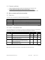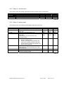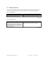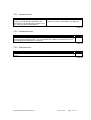
1
SULLAIR MICROVISOR
P2
T1
H
Service
F
M1 / M2
Auto
Status
Power
Page
Manuel d’utilisation FRANÇAIS
2
User Manual ENGLISH 11
MICROVISOR Manual 68562144
Page 1 of 19
Table des matières
1 INTERFACE UTILISATEUR ................................................................................................................. 3
1.1
1.2
1.3
2
MESSAGE ........................................................................................................................................ 3
BOUTONS ........................................................................................................................................ 4
LED’S TE) ...................................................................................................................................... 4
MENUS DE BASE ET FONCTIONS................................................................................................. 5
2.1
CODE ACCES / MODIFICATION DES PARAMETRES ............................................................................. 5
2.1.1
Code entrée menu 1,2 ............................................................................................................ 5
2.1.2
Code entrée menu 3 ................................................................................................................ 5
2.1.3
Modification des parmètres .................................................................................................... 6
2.2
MENUS, PARAMETRES ET FONCTIONS ............................................................................................. 6
2.2.1
Menu de base .......................................................................................................................... 6
2.2.2
Menu 1 - menu utilisateur...................................................................................................... 6
2.2.3
Menu 2 - Menu maintenance .................................................................................................. 7
2.2.4
Menu 3 - Réglage usine .......................................................................................................... 7
Autres parametres.................................................................................................................. 8
3.3.1
Tempo étoile / triangle............................................................................................................ 8
3.3.2
Tempo rédémarrage ............................................................................................................... 8
3.3.3
Tempo phase arrêt .................................................................................................................. 9
3.3.4
Tempo démarrage à vide ........................................................................................................ 9
3.3.5
Démarrage par heure ............................................................................................................. 9
3.3.6
Table type de réglage............................................................................................................ 10
3.3.7
Micro coupures .................................................................................................................... 10
2
MICROVISOR Manual 68562144
Janvier 2003
Page 2 sur 19
1 Interface Utilisateur
Message
Vue
Marche
P2
T1
Stop
H
Service
Haut
F
M1 / M2
Bas
Auto
Status
Power
Reset
LED indicatrices
1.1
Message
Messages :
Message
Run
LoAd
AirF
OIL
---StoP
≡
P co
Signification
Heures de fonctionnement
Heures en charge .
Heures restantes avant maintenance du filtre à air .
Heures restantes avant maintenance du filtre à huile.
Défaut capteur.
Arrêt d’urgence.
Micro coupure sur le réseau électrique
Dépassement de la Pression sur le réseau
Table 1
MICROVISOR Manual 68562144
Janvier 2003
Page 3 sur 19
1.2
Boutons
Bouton
Vue
Marche
Arrêt
Haut
Bas
Reset
Fonction
Active le menu déroulant sélectionné.
Marche du compresseur locallement.
Arrêt du compresseur locallement.
Incrémente la valeur actuellement affichée.
Décrémente la valeur actuellement affichée.
Retour au menu principal ou
Efface un défaut / une alarme.
Table 2
1.3
LED
•
•
•
Continu: fonctionement correct
Clignotement lent: alarme
Clignotement rapide : arrêt .
LED
P2
Etat
• Continu
• Clignotement Lent
T1
•
•
•
Continu
Clignotement Lent
Clignotement rapide
H
Service
•
•
•
•
•
•
•
•
•
•
•
continu
Continu
Clignotement Lent
Clignotement Lent
Clignotement rapide
Continu
Clignotement rapide
Continu
Clignotement Lent
Clignotement rapide
Continu
F
M1 / M2
Auto
Status
Power
Explication
• Affichage de la pression
• Arrêt par une pression haute.
• Un clignotement rapide et des traits indiquent un
défaut du capteur de pression.
• Affichage de la température.
• Alarme température
• Arrêt température .
Un clignotement rapide et des traits indiquent un
défaut du capteur de température.
• Affichage des heures de fonctionnement.
• Heures restantes avant maintenance.
• Alarme : Faire la maintenance du filtre air ou huile
• Non utilisé.
• Arrêt : Thermique moteur principal / ventilateur.
• Démarrage auto / distance
• Alarme : le compresseur va redémarrer
• Compresseur fonctionne.
• Alarme : Le compresseur est à vide.
• Alarme : le compresseur va redémarrer
• Le Contrôleur est sous tension.
Table 3
!
Note: Toutes les LEDS clignotent et l’afficheur affiche StoP: l’arrêt d’urgence est actionné. Les
nouvelles valeurs rentrées seront mémorisées.
2 Menus / paramètres et fonctions
2.1
Code accès / Modification des paramètres
2.1.1 Code accès menu 1 et menu 2
MICROVISOR Manual 68562144
Janvier 2003
Page 4 sur 19
•
•
•
•
Appuyer sur les touches "haut" et "bas" en même temps pendant 5 secondes ( étape 1).
Quand il apparaît “-00- “ sur l’afficheur, sélectionner avec le touches haut / bas le nombre 1
(étape 2).
Après affichage du nombre 1, ne plus toucher à d’autres touches ( étape 3).
Le premier paramètre va automatiquement s’afficher.
Etape 2
P2
T1
H
Service
F
M1 / M2
Auto
Status
Etape 1 et 3
Power
2.1.2 Code accès menu 3
•
•
•
•
Appuyer sur les touches "haut" et "bas" en même temps pendant 5 secondes ( étape 1).
Quand il apparaît “-00- “ sur l’afficheur, sélectionner avec le touches haut / bas le nombre 3
(étape 2).
Après affichage du nombre désiré, appuyer sur la touche stop ( étape 4).
Maintenir appuyer la touche stop jusqu’à l’affichage du premier paramètre (étape 4).
Etape 2
P2
Etape 4
T1
Run/Load hours
Service
F
M1 / M2
Auto
Etape 1 and 3
Status
Power
MICROVISOR Manual 68562144
Janvier 2003
Page 5 sur 19
2.1.3 Modification des paramètres
•
•
•
•
2.2
Sélectionner le paramètre désiré à l’aide de la touche vue.
Modifier la valeur du paramètre à l’aide des touches haut et bas.
La nouvelle valeur sera mémorisée dès que la valeur ne clignotera plus.
Passer au paramètre suivant.
Menus, paramètres et fonctions
2.2.1 Menu de base
LED / Message
P2
T1
H run
H load
Service Air f
Service Oil
Fonction
Affichage de la pression.
Affichage de la température.
Affichage des heures de fonctionnement
Affichage des heures en charge
Heures restantes avant maintenance du filtre à air.
Heures restantes avant maintenance du filtre à huile
Table 4
2.2.2 Menu 1 – Menu utilisateur
LED /
Message
P2
Fonction
Defaut
Min.
Max.
Le compresseur passe à vide, pression haute.
P2
Le compresseur passe en charge, pression basse.
F
M1 / M2
Auto
Durée de purge du drain séparateur de condensats.
Intervalle de purge du drain séparateur de condensats.
Tempo de redémarrage après une coupure secteur
(évite le démarrage de plusieurs compresseurs en
même temps).
Temps de mise à vide avant arrêt du compresseur.
Numéro du compresseur ( si réseau RS485 ).
7.5 Bar
109 PSI
6 Bar
87 PSI
5sec
30sec
0
Load
level
5 Bar
73PSI
0.5sec
10sec
9sec
15 Bar
218 PSI
Unload
level
10sec
120sec
240sec
10min
1
1min
1
240Min
32
Status
Ad 1
Table 5
Note: Le drain est inactif en marche à vide ou à l’arrêt.
MICROVISOR Manual 68562144
Janvier 2003
Page 6 sur 19
2.2.3 Menu 2 – Menu maintenance
LED /
message
Service air f
Sevice oil
Fonction
Defaut
Min.
Max.
Changement du filtre à air en heures
Changement du filtre à huile en heures
500
500
0 hours
0 hours
2000
4000
Table 6
2.2.4 Menu 3 – Réglage usine
LED / Message
P2 bar
P2 maxi
Fonction
Selectionne l’unité de pression.
Pression maxi sortie utilisateur, arrêt
T2 cels
T2 maxi
Selectionne l’unité de température
Température maxi sortie ail / huile, arrêt
Alert
•
TP 7
H run
H load
Alarme : Le relais n’est pas alimenté en
cas de défaut .
• Contrôle : Le relais est activé quand le
compresseur est disponible ( marche est
activée et il n’ y a pas de défaut ).
Selon le type de réglage, certains paramètres
sont automatiquement réglés ( voir Table 13 )
Heure total de fonctionnement
Heure total en charge
Defaut
Bar
7.5 Bar
109 PSI
cels
110°C
230 F
Alr
Min.
Bar
6 Bar
87 PSI
cels
90°C
194 F
ALr
Max.
PSI
16 Bar
232 PSI
FarH
125°C
257 F
Cont
1
1
18
0
0
0
0
100000
100000
Table 7
MICROVISOR Manual 68562144
Janvier 2003
Page 7 sur 19
2.3
Autres parametres
Certains de ces paramètres suivant sont modifiés automatiquement modifiés selon la table 15.
D’autres ne peuvent d’être modifiés que par changement de la mémoire.
2.3.1 Tempo Etoile Triangle
Fonction
Temps de passage de étoile à triangle
Réglage
Voir table 15
Table 8
2.3.2 Tempo rédémarrage
Fonction
C’est le temps nécessaire après un arrêt du
compresseur pour que la pression du
séparateur soit à zéro, elle évite un
redémarrage en charge du compresseur.
Réglage
Voir table 15
Table 9
MICROVISOR Manual 68562144
Janvier 2003
Page 8 sur 19
2.3.3 Tempo phase arrêt
Fonction
C’est le temps pendant lequel le compresseur
tournera à vide après un appui sur la touche
stop. Cette fonction permet arrêt hors charge
du compresseur
Réglage
Voir Table 15
Table 10
2.3.4 Tempo démarrage à vide
Function
C’est le temps pendant lequel le compresseur restera à vide au démarrage. Ce temps
doit-être supérieur au temps étoile triangle.
Defaut
2sec
Table 11
2.3.5 Démarrage par heure
Fonction
Limite le nombre de démarrage par heure.
Defaut
0
Table 12
.
MICROVISOR Manual 68562144
Janvier 2003
Page 9 sur 19
2.3.6 Table type de réglage
Les paramètres listés ci-dessous sont automatiquement entrés par le type selectionné.
Type
Etoile
triangle (s)
Tempo
rédémarrge
1
2
3
4
5
6
7
8
9
10
11
12
13
14
15
16
17
18
3.0
4.0
3.0
4.0
3.0
4.0
5.0
6.0
5.0
6.0
5.0
6.0
8.0
9.0
8.0
9.0
8.0
9.0
60
120
60
120
60
120
120
180
120
180
120
180
120
180
120
180
120
180
Tempo
phase arrêt
(s)
10
10
10
10
10
10
10
10
10
10
10
10
10
10
10
10
10
10
Pression en
charge (bar)
Pression à
vide (bar)
Pression
max. (bar)
6.0
6.0
8.5
8.5
11.5
11.5
6.0
6.0
8.5
8.5
11.5
11.5
6.0
6.0
8.5
8.5
11.5
11.5
7.5
7.5
10.0
10.0
13.0
13.0
6.5
6.5
10.0
10.0
13.0
13.0
7.5
7.5
10.0
10.0
13.0
13.0
8.5
8.5
11.0
11.0
14.0
14.0
8.5
8.5
11.0
11.0
14.0
14.0
8.5
8.5
11.0
11.0
14.0
14.0
Table 13
2.3.7 Micro coupures
Fonction
Le contrôleur détecte les micro-coupures. Le compresseur sera arrêté si une
micro-coupure supérieure à 40 ms est détectée, 3 traits horizontaux seront
Affichés.
Réglage par
défaut
40ms
Table 14
MICROVISOR Manual 68562144
Janvier 2003
Page 10 sur 19
Table of contents
1 USER INTERFACE................................................................................................................................ 12
1.1
1.2
1.3
2
DISPLAY ........................................................................................................................................ 12
PUSH BUTTONS .............................................................................................................................. 13
LED’S ........................................................................................................................................... 13
BASIC SOFTWARE MENUS AND FUNCTIONS......................................................................... 14
2.1
MENU CODE ENTRY / PARAMETER MODIFICATION ......................................................................... 14
2.1.1
Entering menu 1,2............................................................................................................... 141
2.1.2
Entering menu 3.................................................................................................................... 14
2.1.3
Parameter modification ........................................................................................................ 15
2.2
MENUS, PARAMETER AND FUNCTION DESCRIPTION ....................................................................... 15
2.2.1
Basic menu............................................................................................................................ 15
2.2.2
Menu 1 - user parameter menu............................................................................................. 15
2.2.3
Menu 2 - service menu.......................................................................................................... 16
2.2.4
Menu 3 - factory menu.......................................................................................................... 16
2.3
ADDITIONAL PARAMETERS ............................................................................................................ 17
3.3.1
Star delta time....................................................................................................................... 17
3.3.2
Blow down time .................................................................................................................... 17
3.3.3
Unload run time.................................................................................................................... 18
3.3.4
Acceleration time .................................................................................................................. 18
3.3.5
Starts per hour ...................................................................................................................... 18
3.3.6
Type selection table .............................................................................................................. 19
3.3.7
Micro power interruptions.................................................................................................... 19
1
MICROVISOR Manual 68562144
Janvier 2003
Page 11 sur 19
1 Interface User
Display
View
Start
P2
T1
Stop
H
Service
Up
F
M1 / M2
Down
Auto
Satus
Power
Reset
Indication LEDS
1.1
Display
Messages :
Message
Run
LoAd
AirF
OIL
---StoP
≡
P co
Meaning
Running hours
Loaded hours .
Remaining hours to air filter service are being displayed.
Remaining hours to oil service are being displayed.
Indicating a sensor error;
Indicating that the emergency stop input has been opened.
A micro power interruption has been detected
Indicating an excess internal pressure fault.
Table 15
MICROVISOR Manual 68562144
Janvier 2003
Page 12 sur 19
1.2
Push buttons
Button
View
Start
Stop
Up
Down
Reset
Function
Scrolling through a selected menu.
Starting the compressor locally.
Stopping the compressor locally.
Increase of the value on the display.
Decrease of the value on the display.
Return to the basic menu or
Reset of the controller whenever an alarm/warning has
occurred.
Table 16
1.3
LED’s
•
•
•
Continuous: showing data / information; everything OK.
Slow blinking: warning indication; check the compressor.
Fast blinking: shut down indication; the controller has taken action.
LED
P2
Status
• Continuous
• Fast blinking
T1
•
•
•
Continuous
Slow Blinking
Fast blinking
H
Service
•
•
•
continuous
continuous
Slow Blinking
F
M1 / M2
Auto
•
•
•
•
•
•
•
•
Slow Blinking
Fast blinking
continuous
Fast blinking
continuous
Slow Blinking
Fast blinking
continuous
Satus
Power
Explanation
• Pressure is being displayed.
• Shut down : the pressure has reached shut down
level.
• A fast blinking led in combination with dashes on the
display, a pressure sensor error is indicated.(see also
Table 1 on page 3).
• Temperature is being displayed.
• Warning : temperature has reached alarm level
• Shut down : the temperature has reached shut down
level.
• A fast blinking led in combination with dashes on the
display, a temperature sensor error is indicated
(see also Table 1 on page 3).
• Running / loaded hours are being displayed.
• Remaining hours to service are being displayed.
• Warning : service is required (the display will toggle
between the remaining hours and the items that need
to be serviced).
• Not used
• Shut down : main motor winding temperature too high.
• Either auto restart or remote control has been enabled
• Warning : machine will start as soon as it is allowed to
• Motor running.
• Warning : machine is blowing down.
• Warning : machine will start as soon as it is allowed to
• Controller is powered.
Table 17
!
Note: when all the LEDS are blinking and the display shows StoP, this means the emergency stop
input has been opened. Remember also that new values will be stored into the memory while
the emergency stop input is opened.
MICROVISOR Manual 68562144
Janvier 2003
Page 13 sur 19
2 Basic software menus and functions
2.1
Menu code entry / parameter modification
This paragraph explains how to select one of the menu’s and scroll through the different parameters.
The 5 Microvisor menus can be accessed very easily. However, menu 3,4 and 5 are password
protected.
2.1.1 Entering menu 1,2
•
•
•
•
Press up and down button at the same time for 5 seconds (step 1).
When “-00- “ appears on the display, select with the up and down button number 1 (step 2).
After number 1 is set, do not touch any buttons (step 3).
Automatically the first parameter of the first menu is shown.
Step 2
P2
T1
H
Service
F
M1 / M2
Step 1 and 3
Auto
Satus
Power
2.1.2 Entering menu 3
•
•
•
•
Press up and down button at the same time for 5 seconds (step 1).
When “-00- “ appears on the display (step 2), select with the up and down button the desired
number that corresponds with the menu to be entered (step 3).
After the desired number is set, push the stop button (step 4).
Keep the stop button pushed until the first parameter of the selected menu is shown (step 4).
Step 2
P2
Step 4
T1
H
Service
F
M1 / M2
Auto
Step 1 and 3
Satus
Power
MICROVISOR Manual 68562144
Janvier 2003
Page 14 sur 19
2.1.3 Parameter modification
•
•
•
•
2.2
Select the desired parameter by means of the view button in the respective menu.
Change the parameter’s value with the up / down push button.
The new value is only stored into the memory when the value stops blinking.
When a steady value is displayed, go to the next parameter or return to the basic menu.
Menus, parameter and function description
2.2.1 Basic menu
In the basic menu, the operator can obtain the following information:
LED / Message
P2
T1
H run
H load
Service Air f
Service Oil
Function
Line pressure is displayed.
Temperature is being displayed.
Total amount of running hours are being displayed.
Total amount of loaded hours are being displayed.
Remaining hours to air filter service are being displayed.
Remaining hours to oil service are being displayed.
Table 18
2.2.2 Menu 1 - user parameter menu
In the user parameter menu, the operator can make some modifications according to his requirements.
The following parameters can be accessed and changed by the operator in this menu:
LED /
Message
P2
Function
Default
Min.
Max.
From this level the machine starts working offload.
P2
From this level the machine starts working load.
F
Opening time of the drain to release the moisture
of the after cooling process.
Opening interval of the drain.
Automatic restart of the machine after a power
failure in case when the machine was running
before the power failure.
The amount of time that the motor keeps on
running idle before it stops.
Address of the controller in an RS485 network.
7.5 Bar
109 PSI
6 Bar
87 PSI
5sec
Load
level
5 Bar
73PSI
0.5sec
15 Bar
218 PSI
Unload
level
10sec
30sec
0
10sec
9sec
120sec
240sec
10min
1min
240Min
1
1
32
M1 / M2
Auto
Status
Ad 1
Table 19
Note: When the machine is not running or running offload, the drain is kept closed.
MICROVISOR Manual 68562144
Janvier 2003
Page 15 sur 19
2.2.3 Menu 2 - service menu
In the service menu the following programmed service timers can be set and reset:
LED /
Message
Service air f
Service oil
Function
Default
Min.
Max.
Air filter time.
Oil filter life time.
500
500
0 hours
0 hours
2000
4000
Table 20
2.2.4 Menu 3 - factory menu
In the factory menu, the following fundamental parameters can be set:
LED / Message
P2 bar
P2 maxi
T1 cels
T1 maxi
Alert
TP 7
H run
H load
Function
Selection of the pressure unit.
The pressure limit on which the machine is
shut down.
Selection of the temperature unit.
The temperature limit on which the machine is
shut down.
Automatically the warning level is set
10°C/85°F lower.
• Alarm : the relay is not powered in case
an error or fault occurs.
• Control : the relay is powered when the
machine is available (meaning: the start
button has been pushed and there are no
errors on the machine).
According to the type selection certain
parameters are set automatically (see Table
13 on page 10).
Total amount of the machine’s running hours.
Total amount of the hours that the machine
has been working loaded.
Default
Bar
7.5 Bar
109 PSI
cels
110°C
230 F
Min.
Bar
6 Bar
87 PSI
cels
90°C
194 F
Max.
PSI
16 Bar
232 PSI
FarH
125°C
257 F
Alr
ALr
Cont
1
1
18
0
0
0
0
100000
100000
Table 21
MICROVISOR Manual 68562144
Janvier 2003
Page 16 sur 19
2.3
Additional parameters
Some of the below-described parameters are set automatically when a type is selected (see Table 13
on page 10). Other parameter require a software change in order to change the default setting.
2.3.1 Star delta time
Function
The star delta time is the time the star relay is
powered before powering the delta relay.
Set up
This time is set automatically when a type of
machine in chosen. (See Table 13 on page 10 ).
Table 22
2.3.2 Blow down time
Function
The blow down time is the required time to
depressurize the machine internally when the
motor has stopped running. This time must be
expired before the machine can start again in
order to avoid a start procedure against a too
high internal pressure.
Set up
This time is set automatically when a type of
machine in chosen. (see Table 13 on page 10).
Table 23
MICROVISOR Manual 68562144
Janvier 2003
Page 17 sur 19
2.3.3 Unload run time
Function
The unload run time is the time that the motor
keeps on running after the stop button has
been pushed. By stopping the machine in this
way, internal pressure is decreased.
Set up
This time is set automatically when a type of
machine in chosen. (see Table 13 on page 10)
Table 24
2.3.4 Acceleration time
Function
The acceleration time is the time between the powering the delta relay and the powering
of the load/unload solenoid valve. This acceleration time makes sure that the motor is at
its full speed before loading the compressor.
Default
2sec
Table 25
2.3.5 Starts per hour
Function
This safety function prevents the compressor from starting too often within a time span of
1 hour.
Default
0
Table 26
MICROVISOR Manual 68562144
Janvier 2003
Page 18 sur 19
2.3.6 Type selection table
The parameters that are listed below are automatically set when a type or model is selected .
Type
Star delta
time (s)
Blow down
time (s)
Unload run
time (s)
Default load
pressure
(bar)
1
2
3
4
5
6
7
8
9
10
11
12
13
14
15
16
17
18
3.0
4.0
3.0
4.0
3.0
4.0
5.0
6.0
5.0
6.0
5.0
6.0
8.0
9.0
8.0
9.0
8.0
9.0
60
120
60
120
60
120
120
180
120
180
120
180
120
180
120
180
120
180
10
10
10
10
10
10
10
10
10
10
10
10
10
10
10
10
10
10
6.0
6.0
8.5
8.5
11.5
11.5
6.0
6.0
8.5
8.5
11.5
11.5
6.0
6.0
8.5
8.5
11.5
11.5
Default
unload
pressure
(bar)
7.5
7.5
10.0
10.0
13.0
13.0
6.5
6.5
10.0
10.0
13.0
13.0
7.5
7.5
10.0
10.0
13.0
13.0
Max.
pressure
(bar)
8.5
8.5
11.0
11.0
14.0
14.0
8.5
8.5
11.0
11.0
14.0
14.0
8.5
8.5
11.0
11.0
14.0
14.0
Table 27
2.3.7 Micro interruption of the power supply
Function
The Microvisor is standard equipped with a device that detects a micro
interruption of the power supply. Compressor will be stopped if the miointerruption is > 40 sec, 3 horizontal dashes will be displayed.
Default setting
40ms
Table 28
MICROVISOR Manual 68562144
Janvier 2003
Page 19 sur 19