1
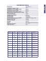
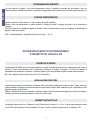
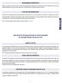
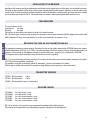
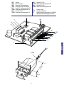
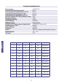
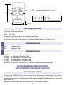
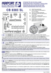
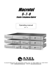
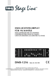
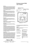
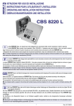
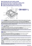
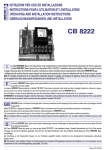
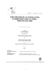
ISTRUZIONI PER USO ED INSTALLAZIONE
INSTRUCTIONS POUR L’UTILISATION ET L’INSTALLATION
OPERATING AND INSTALLATION INSTRUCTIONS
GEBRAUCHSANWEISUNGEN UND INSTALLATION
TAC 11 RKA PLUS
TAC 12 RKA PLUS
TAC 14 RKA PLUS
La ditta FERPORT S.a.s. non risponde per errati collegamenti e/o manomissioni delle centrali e tantomeno le riterrà in garanzia.
La ditta FERPORT S.a.s. precisa di aver depositato il Mod. TAC 11RKA/12RKA/14RKA-PLUS. Il medesimo sarà quindi tutelata in tutte le
sue parti a norma di legge. Nessuna parte del contenuto di questo manuale può essere riprodotta senza autorizzazione scritta della FERPORT S.a.s.
I collegamenti alla centrale devono essere eseguiti solo da personale specializzato e dopo aver attentamente letto le istruzioni sopra riportate.
N.B.: E’ richiesto l’inserimento di un interruttore onnipolare presso la centrale, con distanza di apertura minima dei contatti di 3 mm, per lo spegnimento
della stessa prima dell’apertura per manutenzione (CEI 64-8).
I
La maison FERPORT S.a.s. dégage toute responsabilité en cas de mauvaises connexions et/ou endommagement des unités. En pareil cas
la garantie n’est pas valable.
La maison FERPORT S.a.s.a déposé le Modèle TAC 11RKA/12RKA/14RKA-PLUS. Toute pièce composant cette unité sera donc protégée d'après les
normes en vigueur. Aucune partie de ce manuel d’utilisation ne peut être reproduite sans l’autorisation écrite de FERPORT S.a.s.
Les connexions à l’unité ne seront effectuées que par des techniciens qualifiés et après avoir attentivement lu les instructions ci-dessus.
ATTENTION! Il est nécessaire d’équiper l’unité d’un interrupteur omnipolaire, avent une distance d’ouverture minimum des contacts de 3 mm. ce qui
permet la mise hors service de celle-ci avant l’ouverture lors des opérations l’entretien (CEI 64-8).
F
S.a.s. is not liable for damages due to incorrect connections and/or tampering of the receivers neither are such damages covered
GB byFERPORT
guarantee.
Model TAC 11RKA/12RKA/ 14RKA-PLUS is a registered trademark of FERPORT S.a.s. Such devices and all its parts are protected according to the
existing laws.
No part of this guide may be reproduced without the prior written permission of FERPORT S.a.s.
The connections to the terminal board are to be carried out by qualified people after having read the above mentioned instructions.
NB: An omnipolar switch is required in the terminal with contacts having a minimum distance of 3 mm, in order to switch it off before servicing (CEI
64-8).
Die Firma FERPORT S.a.s. steht nicht für falsche Verbindungen und/oder Verletzungen der Steuereinheiten ein und wird sie auf jeden Fall
nicht in der Garantie einbeziehen.
Die Firma FERPORT S.a.s. gibt genau an, dass sie das Modell TAC 11RKA/12RKA/14RKA-PLUS hat patentieren lassen. Dieselbe Steuereinheit und
all ihre Teile werden deswegen auf Grund des Gesetzes geschützt. Man darf kein Teil dieses Handbuchs ohne die schriftliche Genehmigung der Firma
FERPORT S.a.s. vervielfältigen.
Die Anschlüsse an die Steuereinheit müssen nur von Fachleuten ausgeführt werden, nachdem sie die obengenannten Anweisungen aufmerksam
gelesen haben.
NB: Man braucht, einen allpoligen Schalter an die Steuereinheit mit mindestem Öffnungsabstand zwischen den Kontakten von 3 mm einzusetzen, der
die Steuereinheit vor der Instandhaltungsöffnung ausschaltet. (CEI 64-8)
D
1
Rev. 001 09/03
ITALIANO
ANT
GND
GND
ALIM
NA 1
COM1
NA 2
COM2
NA 3
antenna
massa antenna
negativo alimentazione
alimentazione 12/24V ac/dc
contatto N.A. CH1
comune CH1
contatto N.A. CH2
comune CH2
contatto N.A. CH3
COM3
NA 4
COM4
comune CH3
contatto N.A. CH4
comune CH4
P
ANT
J1
pulsante funzioni
attacco antenna
Chiuso alim. 12V ac/dc
Aperto alim. 24V ac/d
P
L1
L3
ANT
L2
L4
ANT
GND
GND
ALIM
COM 1
NA 1
COM 2
NA 2
COM 3
NA 3
COM 4
NA 4
J1
O RING
92,
5m
m
85 m
m
37 mm
2
Alimentazione
Assorbimento a riposo a 12 VAC
Assorbimento con relé eccitato a 12 VCC
Assorbimento a riposo a 24 VAC
Assorbimento con relé eccitato a 24 VCC
Massima potenza commutabile dai relé a 24 VAC
Ritardo nell’eccitazione
Ritardo alla diseccitazione
Oscillatore locale
Ricevitore di tipo
Sensibilità misurata con segnale ON-OFF
Banda passante a -3 dB
Radiazione in antenna
Decodifica
Antenna
Temperatura di esercizio
Grado di protezione
12/24 VAC VCC
20 mA
35,3 mA
33,7 mA
69,2 mA
24VA
140 mS
140 mS
433,42 MHz
Superterodina
>=110 Dbm s/n 17 dB mod. 100%
500 KHz
>-65 dBm
tramite uP
Stilo 1/4 facente parte integrale del sistema
-20° ÷ + 70°
IP 55
IMPULSO
LED L1
LED L2
LED L3
LED L4
MODALITÁ
1
ON
OFF
OFF
OFF
Monostabile CH1
2
OFF
ON
OFF
OFF
Bistabile CH1
3
ON
ON
OFF
OFF
Temporizzato CH1
4
OFF
OFF
ON
OFF
Monostabile CH2
5
ON
OFF
ON
OFF
Bistabile CH2
6
OFF
ON
ON
OFF
Temporizzato CH2
7
ON
ON
ON
OFF
Monostabile CH3
8
OFF
OFF
OFF
ON
Bistabile CH3
9
ON
OFF
OFF
ON
Temporizzato CH3
10
OFF
ON
OFF
ON
Monostabile CH4
11
ON
ON
OFF
ON
Bistabile CH4
12
OFF
OFF
ON
ON
Temporizzato CH4
3
ITALIANO
CARATTERISTICHE TECNICHE
PROGRAMMAZIONE RICEVENTE
ITALIANO
Una volta premuto il pulsante P nel modo programmazione voluto e constatato l’accensione del led premere il tasto sul
radiocomando che si desidera memorizzare e constatare lo spegnimento del led a questo punto la ricevente sarà pronta per l’uso.
FUNZIONE TEMPORIZZATORE
Premere il pulsante P sulla ricevente n. x volte a seconda del canale desiderato.
Premere il tasto sul radiocomando, in questo momento la scheda ha iniziato il conteggio del tempo (i led si accendono in
sequenza).
Trascorso il tempo da noi desiderato premere nuovamente il tasto sul radiocomando premuto in precedenza, la scheda radio ha
appreso il tempo da noi settato.
N.B.: il funzionamento è possibile averlo sia sul relè 1 - 2 o 4.
DESCRIZIONE RICEVENTI AUTOAPPRENDIMENTO
E TRASMETTITORI TAC2K/4K A DIP
POSSIBILITÀ DI IMPIEGO
Il radiocomando TAC2K/4K trova il suo miglior impiego nel comando a distanza di porte, portoni e cancelli motorizzati, sistemi di
antifurto e in tutte quelle situazioni dove sia necessaria un’attivazione a distanza. La portata è di 150-200 mt (distanza di
funzionamento tra trasmettitori e ricevitore). La portata é legata a una corretta installazione nella ricevente dotata di antenna.
N.B.: (Non installare mai due ricevitori a meno di mt 2,5 l’uno dall’altro.
INSTALLAZIONE RICEVITORE
L’installazione del ricevitore e dell’antenna in dotazione deve essere fatta possibilmente nel punto più alto e visibile, lontano da
strutture metalliche. Il fissaggio del ricevitore da esterno avviene tramite la propria staffa, fissandolo con viti o tassellandolo a muro
tenendo presente la messa in bolla.
Effettuati i collegamenti e richiuso il coperchio è sufficiente avvitare l’antenna in dotazione nell’apposito foro situato sul coperchio.
L’antenna deve essere avvitata manualmente e stretta con minimo sforzo.
TRASMETTITORI A DIP 2K-4K
I trasmettitori vengono forniti con 12 dip-switch. I primi 10 servono per la codifica. Il n. 11 e il n. 12 servono per assegnare il canale
al tasto CH2 (vedi illustrazione) sia sul trasmettitore a 2 che a 4 canali. La tabella qui riportata serve a configurare il CH.
4
CH 2
CH 3
CH 4
CH2
11
11
11
11
DIP
ON
123456789101112
Tasto configurabile attraverso i DIP 11 e 12
OFF
OFF
ON
ON
-
12
12
12
12
OFF
ON
OFF
ON
CH2
CH2
CH2
CH2
=
=
=
=
CH1
CH3
CH4
differente dagli altri 3 canali
OFF
43,5 mm
18,5 mm
RICEVITORE A SCHEDA
I ricevitori a scheda potranno essere:
monocanali: un relè
bicanali:
due relè
Le funzioni di questi canali saranno identiche a quelle del ricevitore da esterno.
N.B.: con questo tipo di ricevitori è necessario per una buona portata usare un’antenna esterna (AN433) dotata di cavo coassiale
RG58 (impedenza 50 ohm avente una lunghezza max di mt 10 (quella in dotazione all’antenna è di mt 5).
VERSIONI TRASMETTITORI
TAC2K Trasmettitori
TAC4K Trasmettitori
2 tasti
4 tasti
VERSIONI RICEVENTI
TAC10RKA
Ricev. aut. a scheda 1 relè
TAC10RKA/2 Ricev. aut. a scheda 2 relè
TAC11RKA
Ricev. aut. in cont. c/antenna 1 relè
TAC12RKA
Ricev. aut. in cont. c/antenna 2 relè
TAC14RKA
Ricev. aut. in cont. c/antenna 4 relè
N.B.: tutte le versioni dei ricevitori hanno incorporato le funzioni monostabile-bistabile-temporizzato.
DESCRIZIONE RICEVENTE AUTOAPPRENDIMENTO
E TRASMETTITORI TAC2KA/4KA/8KA “INFRACODE”
POSSIBILITÀ DI IMPIEGO
Il radiocomando TAC2KA/4KA trova il suo miglior impiego nel comando a distanza di porte, portoni e cancelli motorizzati, sistemi
di antifurto e in tutte quelle situazioni dove sia necessaria un’attivazione a distanza. La portata è di 50-100 mt (distanza di
funzionamento tra trasmettitori e ricevitore). La portata é legata a una corretta installazione nella ricevente dotata di antenna.
N.B.: (Non installare mai due ricevitori a meno di mt 2,5 l’uno dall’altro.
5
ITALIANO
78 mm
CH 1
ITALIANO
INSTALLAZIONE RICEVITORE
L’installazione del ricevitore e dell’antenna in dotazione deve essere fatta possibilmente nel punto più alto e visibile, lontano da
strutture metalliche. Il fissaggio del ricevitore da esterno avviene tramite la propria staffa, fissandolo con viti o tassellandolo a muro
tenendo presente la messa in bolla.
Effettuati i collegamenti e richiuso il coperchio è sufficiente avvitare l’antenna in dotazione nell’apposito foro situato sul coperchio.
L’antenna deve essere avvitata manualmente e stretta con minimo sforzo.
RICEVITORE A SCHEDA
I ricevitori a scheda potranno essere:
monocanali: un relè
bicanali:
due relè
Le funzioni di questi canali saranno identiche a quelle del ricevitore da esterno.
N.B.: con questo tipo di ricevitori è necessario per una buona portata usare un’antenna esterna (AN433) dotata di cavo coassiale
RG58 (impedenza 50 ohm avente una lunghezza max di mt 10 (quella in dotazione all’antenna è di mt 5).
APPRENDIMENTO DEL CODICE SUL TRASMETTITORE 2KA/4KA
L’apparecchio possiede un ricevitore all’infrarosso. L’apprendimento del codice e la relativa memorizzazione su EEPROM viene
effettuato usando un codificatore emettitore all’infrarosso TAC1SC o VS CODE). Questo emette la sequenza di bit da memorizzare
tramite un diodo emettitore all’infrarosso. La sequenza di bit viene ricevuta dal nostro apparecchio tramite un ricevitore all’infrarosso
e, “trattata” dal uP, viene memorizzata in EEPROM.
Questa sequenza di bit (codice) verrà trasmessa tutte le volte che si azionerà il telecomando.
N.B.: Per un corretto funzionamento e un più velore apprendimento del codice da parte del trasmettitore, assicurarsi che la batteria
contenuta nel codificatore (TAC1SC) e nel trasmettitore sia efficiente.
Possibilità di codifica con batteria nuova circa 90 trasmettitori. Usare pile mini stilo 12V alcaline. Con questo tipo di codificatore e
trasmettitore è possibile assegnare un codice diverso su ogni tasto del telecomando.
VERSIONI TRASMETTITORI
TAC2KA Trasmettitore mini
TAC4KA Trasmettitore mini
TAC8KA Trasmettitore mini
2 tasti
4 tasti
4 tasti x 2 (con switch)
VERSIONI RICEVENTI
TAC10RKA
TAC10RKA/2
TAC11RKA
TAC12RKA
TAC14RKA
Ricev. aut. a scheda 1 relè
Ricev. aut. a scheda 2 relè
Ricev. aut. in cont. c/antenna 1 relè
Ricev. aut. in cont. c/antenna 2 relè
Ricev. aut. in cont. c/antenna 4 relè
N.B.: tutte le versioni dei ricevitori hanno incorporato le funzioni monostabile-bistabile-temporizzato.
6
ANT
GND
GND
ALIM
NA 1
COM1
NA 2
COM2
antenna
masse antenne
masse aliment.
aliment. 12Vcc 24 Vac
norm. ouvert CH1
commum CH1
norm. ouvert CH2
commum CH2
NA 3
COM3
NA 4
COM4
norm. ouvert CH3
commum CH3
norm. ouvert CH4
commum CH4
P
bouton push bottom
ANT
branchenment d’antenne
J1
fermature 12V ac/dc
ouverture 24V ac/d
P
L1
FRANÇAISE
L3
ANT
L2
L4
ANT
GND
GND
ALIM
COM 1
NA 1
COM 2
NA 2
COM 3
NA 3
COM 4
NA 4
J1
O RING
92,
5m
m
85 m
m
37 mm
7
FRANÇAISE
CARACTERISTIQUES TECHNIQUES
Alimentation
Absorption au repos 12 VCC
Absorption avec realys excité 12 VCC
Absorption au repos 24 VAC
Absorption avec realys excité 24 VCC
Puissance maximum commutabile par relais 24 VAC
Retard à l’excitation
Retard à l’desexcitation
Oscillateur local
Ricepteur type
Sensibilité relevé par signal ON-OFF
Bande passante a -3 dB
Rayonnement en antenne
Décodega
Antenne
Tempèrature de marche
Degré de protection
12/24 VAC VCC
20 mA
35,3 mA
33,7 mA
69,2 mA
24VA
140 mS
140 mS
433,42 MHz
Superterodina
>=110 Dbm s/n 17 dB mod. 100%
500 KHz
>-65 dBm
tramite uP
Style 1/4 falsant partie intégrale du groupe
-20° ÷ + 70°
IP 55
IMPULSE
VOYANT L1
VOYANT L2
VOYANT L3
VOYANT L4
MODALITÉ
1
ON
OFF
OFF
OFF
Monostable CH1
2
OFF
ON
OFF
OFF
Bistable CH1
3
ON
ON
OFF
OFF
Temporisé CH1
4
OFF
OFF
ON
OFF
Monostable CH2
5
ON
OFF
ON
OFF
Bistable CH2
6
OFF
ON
ON
OFF
Temporisé CH2
7
ON
ON
ON
OFF
Monostable CH3
8
OFF
OFF
OFF
ON
Bistable CH3
9
ON
OFF
OFF
ON
Temporisé CH3
10
OFF
ON
OFF
ON
Monostable CH4
11
ON
ON
OFF
ON
Bistable CH4
12
OFF
OFF
ON
ON
Temporisé CH4
8
PROGRAMMATION RÉCEPTEUR
Après avoir pressé le bouton P dans le mode de programmation désiré et lors de l’activation des leds pressez le bouton de la
radiocommande que vous souhaitez mémoriser. Les leds éteints, le récepteur est prêt à l’usage.
FONCTION CHRONOMETRIQUE
N.B.: Le fonctionnement peut être obtenu à travers le relais 1, 2 ou 4
DESCRIPTION DES RECEPTEURS AUTOPROGRAMME
ET DES EMETTEURS TAC2K/4K A DIP
CHAMPS D’ACTION
La radiocommande TAC2K/4K a pour fonction la commande à distance: des portes, des portillons, des portails automatiques, des
systèmes d’alarmes. C’est à dire tous les domaines où il est nécessaire d’activer à distance. La portée enregistrée est de 150 à
200 mètres (distance de fonctionnement entre l’émetteur et le récepteur). Cette portée dépend, d’une installation correcte du
récepteur pourvu d’une antenne.
N.B.: (Ne jamais installer deux récepteurs à moins de 2,5 métrés l’un de l’autre).
INSTALLATION DU RECEPTEUR
L’installation du récepteur et de l’antenne fournie avec l’appareil doit se réaliser au point le plus haut possible et bien visible, loin
des structures métalliques. La fixation du récepteur à l’extérieur se fait par l’intermédiaire d’une bride en le vissant ou tamponnant
au mur tout en tenant compte de la mise en bulle. Les raccordements effectués et le couvercle fermé, il suffit de visser l’antenne
au trou situé sur le couvercle.
L’antenne est à visser manuellement et sans effort.
EMETTEURS POURVUS D’INTERRUPTEURS DIP 2K-4K
Les émetteurs sont pourvus de 12 interrupteur dip. Les 10 premiers permettent le codage. Les n. 11 et n. 12 permettent d’attribuer
le canal à la touche CH2 (cf. photo ci-contre) aussi bien dans l’émetteur à 2 canaux qu’à cellui à 4 canaux. Le tableau montre
comment configurer la touche CH2.
9
FRANÇAISE
Le bouton P du récepteur peut être pressé plusieurs fols afin de trouver le canal désiré. Au moment où l’on appuie sur le bouton,
la fiche électrique commence le décompte (les leds s’activent en séquence). Le temps enregistré écoulé, appuyez de nouveau sur
le mémé bouton, la fiche radio enregistre la durée que nous avons choisie.
78 mm
CH 1
CH 2
CH 3
CH 4
CH2
11
11
11
11
DIP
ON
123456789101112
Touche configurable en travers DIP 11 et 12
OFF
OFF
ON
ON
-
12
12
12
12
OFF
ON
OFF
ON
CH2
CH2
CH2
CH2
=
=
=
=
CH1
CH3
CH4
différent des autres 3 canaux
FRANÇAISE
OFF
43,5 mm
18,5 mm
RECEPTEUR A CARTE
Les récepteur à carte peuvent être:
monocanaux:
un relais
bicanaux:
deux relais
La fonction de ces canaux sera identique à ceux des récepteurs externe sous boîtier plastique.
N.B.: Avec types de récepteurs, pour avoir une bonne portée, il est nécessaire d’utiliser une antenne extérieure (AN433) dotée
d’une câble coaxiale RG58 (indépendance 50 OHM) d’une longueur de 5 à 10 mètres maximum.
VERSIONS DES EMETTEURS
TAC2K
TAC4K
Mini émetteur
Mini émetteur
2 touches
4 touches
VERSION DES RECEPTEURS
TAC10RKA
Récepteur aut. à fiche 1 relais
TAC10RKA/2 Récepteur aut. à fiche 1 relais
TAC11RKA
Récepteur aut. avec antenne 1 relais
TAC12RKA
Récepteur aut. avec antenne 2 relais
Récepteur aut. avec antenne 4 relais
TAC14RKA
N.B.: Dans chaque version des récepteurs sont incorporées les fonctions-impulsion-télérrupteur-temporisé.
Le constructeur n’est pas responsable des dommages causés par des utilisations aux quelles les appareils ne sont pas destinés.
DESCRIPTION DES RECEPTEURS AUTOPROGRAMME
ET DES EMETTEURS TAC2KA/4KA/8KA “INFRACODE”
CHAMPS D’ACTION
La radiocommande TAC2KA/4KA a pour fonction la commande à distance: des portes, des portillons, des portails automatiques,
des systèmes d’alarmes. C’est à dire tous les domaines où il est nécessaire d’activer à distance. La portée enregistrée est de 50
à 100 mètres (distance de fonctionnement entre l’émetteur et le récepteur). Cette portée dépend, d’une installation correcte du
récepteur pourvu d’une antenne.
N.B.: (Ne jamais installer deux récepteurs à moins de 2,5 métrés l’un de l’autre).
10
INSTALLATION DU RECEPTEUR
L’installation du récepteur et de l’antenne fournie avec l’appareil doit se réaliser au point le plus haut possible et bien visible, loin
des structures métalliques. La fixation du récepteur à l’extérieur se fait par l’intermédiaire d’une bride en le vissant ou tamponnant
au mur tout en tenant compte de la mise en bulle. Les raccordements effectués et le couvercle fermé, il suffit de visser l’antenne
au trou situé sur le couvercle.
L’antenne est à visser manuellement et sans effort.
Les récepteur à carte peuvent être:
monocanaux:
un relais
bicanaux:
deux relais
La fonction de ces canaux sera identique à ceux des récepteurs externe sous boîtier plastique.
N.B.: Avec types de récepteurs, pour avoir une bonne portée, il est nécessaire d’utiliser une antenne extérieure (AN433) dotée
d’une câble coaxiale RG58 (indépendance 50 OHM) d’une longueur de 5 à 10 mètres maximum.
PROGRAMMATION DU CODE DE L’EMETTEUR 2KA/4KA
L’appareil possède un récepteur à infrarouge. La programmation du code et la relative mémorisation sur EEPROM est effectué,
grâce à l’utilisation d’un émetteur codeur à infrarouge (TAC1SC ou VS CODE). celui-ci émet une séquence de bits, à l’aide d’une
diode émettrice infra-rouge afin de mémoriser. La séquence de bits est captée par notre appareil grâce à un récepteur à infrarouge, et “traitée” par UP, elle sera ensuite mémorisée par EEPROM. Cette séquence de bits (codifiée) sera transmise toutes les
fois que s’actionnera le télécommande.
N.B.: Pour un correcte fonctionnement de l’emetteur et une plus grande rapideté dans la programmation du code, il faut s’assurer
que les batteries contenu faut s’assurer que les batteries contenu dans le codeur (TAC1SC) et dans les émetteurs, sont bien
rechargées. Avec des nouvelles batteries, la capacité de condifier est d’environs 90 émetteurs. Utilisé des petites piles de 12V
alkaline, avec ces types de codeurs et d’emetteurs, il sera possible d’attribuer un code diffèrent sur chaque bouton de la
télécommande.
VERSIONS DES EMETTEURS
TAC2KA Mini émetteur
TAC4KA Mini émetteur
TAC8KA Mini émetteur
2 touches
4 touches
4 touches x 2 (avec switch)
VERSION DES RECEPTEURS
TAC10RKA
TAC10RKA/2
TAC11RKA
TAC12RKA
TAC14RKA
Récepteur aut. à fiche 1 relais
Récepteur aut. à fiche 1 relais
Récepteur aut. avec antenne 1 relais
Récepteur aut. avec antenne 2 relais
Récepteur aut. avec antenne 4 relais
N.B.: Dans chaque version des récepteurs sont incorporées les fonctions-impulsion-télérrupteur-temporisé. Le constructeur n’est
pas responsable des dommages causés par des utilisations aux quelles les appareils ne sont pas destinés.
11
FRANÇAISE
RECEPTEUR A CARTE
ANT
GND
GND
ALIM
NA 1
COM1
NA 2
COM2
antenna
mass antenna
mass feeder
feeder 12Vcc 24Vac
na CH1
common CH1
na CH2
common CH2
NA 3
COM3
NA 4
COM4
na CH3
common CH3
na CH4
common CH4
P
ANT
J1
button push bottom
bomier plug
closed 12V ac/dc
open 24V ac/d
P
L1
L3
ANT
L2
L4
ENGLISH
ANT
GND
GND
ALIM
COM 1
NA 1
COM 2
NA 2
COM 3
NA 3
COM 4
NA 4
J1
O RING
92,
5m
m
85 m
m
37 mm
12
12/24 VAC VCC
20 mA
35,3 mA
33,7 mA
69,2 mA
24VA
140 ms
140 ms
433,42 MHz
Superheterodyne
>=110 Dbm s/n 17 dB mod. 100%
500 KHz
>-65 dBm
tramite uP
1/4 Stylus as a part of the system
-20° ÷ + 70°
IP 55
Mass antenna
Consumption quiesecent 12 VCC
Consumption with energised relays at 12 VCC
Consumption quiesecent 24 VAC
Consumption with energised relays at 24 VAC
Max power commutable from relays at VAC
Energizing delay
De-energisid delay
Oscillator
Riceiver
Sensitivity measured with ON-OFF signal
Pass-bande at -3 dB
Antenna radiation
Decoding
Antenna
Operation temperature
Protection degree
IMPULSION
LED L1
LED L2
LED L3
LED L4
MODALITY
1
ON
OFF
OFF
OFF
Monostable CH1
2
OFF
ON
OFF
OFF
Bistable CH1
3
ON
ON
OFF
OFF
Timed CH1
4
OFF
OFF
ON
OFF
Monostable CH2
5
ON
OFF
ON
OFF
Bistable CH2
6
OFF
ON
ON
OFF
Timed CH2
7
ON
ON
ON
OFF
Monostable CH3
8
OFF
OFF
OFF
ON
Bistable CH3
9
ON
OFF
OFF
ON
Timed CH3
10
OFF
ON
OFF
ON
Monostable CH4
11
ON
ON
OFF
ON
Bistable CH4
12
OFF
OFF
ON
ON
Timed CH4
13
ENGLISH
TECHNICAL SPECIFICATIONS
RECEIVING PROGRAMMING
Once the button P in the desired programming mode has been pressed and the switching on of the led noted, press the key on the
radio control that you wish to memorise and note the switching-off of the led/s, at this point the receiver is ready to use.
TIMER
Press the button P of the receiver x number of times according to the channel desired. Press the key on the radio control at this
moment the card begins the countdown (the LED subsequently turn on). Once the desired time has passed, press again the key
of the radio control: the radio card registers the time set.
ENGLISH
N.B.: Operation is possible with either relay 1-2 or 4.
DESCRIPTION OF SELF-RECORDING RECEIVERS
AND TRANSMITTERS TAC2K/4K A DIP
POSSIBLE USE
The radio control TAC2K/4K is best used commanding from a distance doors, large doors and motorised gates, alarm systems and
in all those situations where activation at a distance is necessary. The range is 150-200 mt (working distance between transmitter
and receiver). The range is tied to proper installation of the receiver equipped with an antenna.
N.B.: (never install two receivers at a distance less than 2,5 mt).
INSTALLATION OF THE RECEIVER
Installation of the receiver and the provided antenna must be done at the highest and most visible point, far from metallic structures.
Fixing the receiver is possible carried out by using the proper bracket, attaching it with screws or doweling it to the wall and ensuring
a correct level. Once the connections have been carried out and the lid replaced it is sufficient that the provided antenna is screwed
into the suitable hole situated on the lid. The antenna must be screwed in manually and tightened with minimum force.
DIP TRANSMITTER 2K-4K
The transmitteurs are suplied with 12 dip-switches. The first 10 are for coding. Number 11 and 12 are for CH2 assign (see figure)
both on the 2 and 4 channel transmitters.
The table below is for CH2 configuration.
14
78 mm
CH 1
CH 2
CH 3
CH 4
CH2
11
11
11
11
DIP
ON
123456789101112
Configurabile key through DIP 11 and 12
OFF
OFF
ON
ON
-
12
12
12
12
OFF
ON
OFF
ON
CH2
CH2
CH2
CH2
=
=
=
=
CH1
CH3
CH4
different to the others 3 channels
OFF
43,5 mm
18,5 mm
The card receivers can be:
monochannel:
one relay
bichannel:
two relay
The functions of these channel are identical to those of the external receiver.
N.B.: With these types of receivers for good range it is necessary to use an external antenna (AN433) equipped with coaxial cable
RG58 (impedance 50 ohm) with a max length of 10 mt (the one provided with the antenna is 5 mt).
TRANSMITTER VERSIONS
TAC2K
TAC4K
Mini transmitters
Mini transmitters
2 keys
4 keys
RECEIVER VERSION
TAC10RKA
Aut. card receiver 1 relay
TAC10RKA/2 Aut. card receiver 2 relay
TAC11RKA
Aut. cont. receiver antenna 1 relay
TAC12RKA
Aut. cont. receiver antenna 2 relay
TAC14RKA
Aut. cont. receiver antenna 4 relay
N.B.: All the versions of the receivers have incorporated-monostable-bistable timing functions.
The producer is not responsible for possible damage caused by improper use the said apparatus.
DESCRIPTION OF SELF-RECORDING RECEIVERS
AND TRANSMITTERS TAC2KA/4KA/8KA “INFRACODE”
POSSIBLE USE
The radio control TAC2KA/4KA is best used commanding from a distance doors, large doors and motorised gates, alarm systems
and in all those situations where activation at a distance is necessary. The range is 50-100 mt (working distance between
transmitter and receiver). The range is tied to proper installation of the receiver equipped with an antenna.
N.B.: (never install two receivers at a distance less than 2,5 mt).
15
ENGLISH
CARD RECEIVERS
INSTALLATION OF THE RECEIVER
Installation of the receiver and the provided antenna must be done at the highest and most visible point, far from metallic structures.
Fixing the receiver is possible carried out by using the proper bracket, attaching it with screws or doweling it to the wall and ensuring
a correct level. Once the connections have been carried out and the lid replaced it is sufficient that the provided antenna is screwed
into the suitable hole situated on the lid. The antenna must be screwed in manually and tightened with minimum force.
CARD RECEIVERS
The card receivers can be:
monochannel:
one relay
bichannel:
two relay
The functions of these channel are identical to those of the external receiver.
N.B.: With these types of receivers for good range it is necessary to use an external antenna (AN433) equipped with coaxial cable
RG58 (impedance 50 ohm) with a max length of 10 mt (the one provided with the antenna is 5 mt).
ENGLISH
RECORDING THE CODE ON THE TRANSMITTER 2KA/4KA
The apparatus possesses an infrared receiver. Recording the code and the relative memorisation EEPROM takes place using an
infrared codifier-emitter (TAC1SC or VS CODE). This emits the sequence of bit to memorise using an infrared diode emitter. The
sequence of bit is receiver by the apparatus through an infrared receiver and, “treated” by uP, is memorised in EEPROM.
This sequence of bit (code) is transmitted every time the remote control is operated.
N.B.: For correct functioning and faster recording of the code by the transmitter, ensure that the battery contained in the codifier
(TAC1SC) and in the transmitter are efficient.
It is possible to codify with a new battery (about 90 transmitters). Use mini style batteries 12V alkaline.
Whit this type of codifier and transmitter it is possible to assign different code on each key of the remote control.
TRANSMITTER VERSIONS
TAC2KA Mini transmitters
2 keys
TAC4KA Mini transmitters
4 keys
TAC8KA Mini transmitters 4 keys x 2 (with switch)
RECEIVER VERSION
TAC10RKA
TAC10RKA/2
TAC11RKA
TAC12RKA
TAC14RKA
Aut. card receiver 1 relay
Aut. card receiver 2 relay
Aut. cont. receiver antenna 1 relay
Aut. cont. receiver antenna 2 relay
Aut. cont. receiver antenna 4 relay
N.B.: All the versions of the receivers have incorporated-monostable-bistable timing functions.
The producer is not responsible for possible damage caused by improper use the said apparatus.
16
ANT
GND
GND
ALIM
NA 1
COM1
NA 2
COM2
Antenne
Erde der Antenne
Negativ der Stromversorgung
Stromversorgung 12/24V Ws/Gs
Kontakt N.O – normalerweise offen. CH1
Gemeinsame Erdungseinheit CH1
Kontakt N.O. CH2
Gemeinsame Erdungseinheit CH2
NA 3
COM3
NA 4
COM4
Kontakt N.O. CH3
Gemeinsame Erdungseinheit CH3
Kontakt N.O. CH4
Gemeinsame Erdungseinheit CH4
P
ANT
J1
Funktions-Taste
Anschluss der Antenne
Schließung der Stromversorgung. 12V Ws/Gs
Öffnung der Stromversorgung 24V Ws/Gs
P
L1
L3
ANT
L2
L4
ANT
GND
GND
ALIM
COM 1
NA 1
COM 2
NA 2
COM 3
NA 3
COM 4
NA 4
DEUTSCH
J1
O RING
92,
5m
m
85 m
m
37 mm
17
TECHNISCHE EIGENSCHAFTEN
12/24 VAC VCC
20 mA
35,3 mA
33,7 mA
69,2 mA
24VA
140 ms
140 ms
433,42 MHz
Superheterodyne
>=110 Dbm s/n 17 dB mod. 100%
500 KHz
>-65 dBm
tramite uP
Fühler 1/4 als integrierendes Bestandteil des Systems
-20° ÷ + 70°
IP 55
DEUTSCH
Stromversorgung
Stromaufnahme in Ruhestellung 12 VAC
Stromversorgung mit erregtem Relais bei 12 V Gs
Stromaufnahme in Ruhestellung bei 24 V Ws
Stromaufnahme mit erregtem Relais bei 24 V Gs
Max. durch die Relais zu 24 V Ws umschaltbare Leistung
Erregungsverzögerung
Aberregungsverzögerung
Lokaler Schwinger
Empfänger vom Typ
Durch das ON-OFF Signal gemessene Empfindlichkeit
Durchlassbereich zu -3 dB
Antennenstrahlung
Decodierung
Antenne
Betriebstemperatur
Schutzgrad
IMPULS
LED L1
LED L2
LED L3
LED L4
MODALITÄT
1
ON
OFF
OFF
OFF
Monostabil CH1
2
OFF
ON
OFF
OFF
Bistabil CH1
3
ON
ON
OFF
OFF
Takmässig CH1
4
OFF
OFF
ON
OFF
Monostabil CH2
5
ON
OFF
ON
OFF
Bistabil CH2
6
OFF
ON
ON
OFF
Takmässig CH2
7
ON
ON
ON
OFF
Monostabil CH3
8
OFF
OFF
OFF
ON
Bistabil CH3
9
ON
OFF
OFF
ON
Takmässig CH3
10
OFF
ON
OFF
ON
Monostabil CH4
11
ON
ON
OFF
ON
Bistabil CH4
12
OFF
OFF
ON
ON
Takmässig CH4
18
PROGRAMMIERUNG DES EMPFÄNGER
Ist die Taste P im Mode Programmierung gedrückt und das Aufleuchten der Led festgestellt worden, einen Kanal an der
Funksteuerung drücken, der gespeichert werden soll, und das Erlöschen der Led feststellen, danach ist der Empfänger bereit.
FUNKTION TAKTGEBER
Die Taste P auf dem Empfänger mehrere Male je nach dem gewünschten Kanal drücken.
Die Taste auf der Funksteuerung drücken, in diesem Moment hat der Datenträger begonnen, die Zeit zu zählen (die Led leuchten
in Reihenfolge auf)
Ist die gewünschte Zeit vergangen, erneut die Taste auf der Funksteuerung drücken, der Radio-Datenträger hat die von uns
eingestellte Zeit aufgenommen.
ANM.: Der Betrieb ist sowie an Relais 1 als auch an 2 oder 4 möglich.
ANWENDUNGSMÖGLICHKEITEN
Die Funksteuerung TAC2K/4K findet seine beste Anwendung in der Fernsteuerung von motorbetriebenen Türen und Toren,
Alarmanlagen und all den Situationen, in denen eine Fernsteuerung notwendig ist. Die Reichweite beträgt 150-200 m (Entfernung
zwischen Sender und Empfänger). Die Reichweite hangt mit der korrekten Installierung des Empfängers zusammen, der mit einer
Antenne versehen ist.
ANMERKUNG: nie zwei Empfänger nebeneinander installieren, einen Abstand von mind. 2,5 m voneinander halten.
INSTALLIERUNG EMPFÄNGER
Die Installierung des Empfängers und der mitgelieferten Antenne sollte möglichst am höchsten uns übersichtlichsten Punkt
erfolgen, entfernt von Metallstrukturen. Der Außenempfänger wird mit seiner eigenen Halterung befestigt, indem er nach der
Nivellierung an die Wand angeschraubt wird
Sind die Verbindungen hergestellt und der Deckel geschlossen worden, genügt es, die Antenne in dem eigens dazu bestimmten
Loch auf dem Deckel manuell anzuschrauben.
FUNKSENDER MIT DIP 2K-4K
Die Funksender werden mit 12 dip-switch geliefert. Die ersten 10 dienen zur Kodierung, Nr. 11 und 12 dienen dazu, der Taste CH2
den Kanal zuzuteilen (siehe Abb.), sei es auf dem Sender mit 2 als auch mit 4 Kanälen. Die hier angeführte Tabelle dient zur
Gestaltung der CH.
19
DEUTSCH
BESCHREIBUNG EMPFÄNGER SELBSTLERNEN
UND FUNKSENDER TAC2K/4K A DIP
78 mm
CH 1
CH 2
CH 3
CH 4
CH2
11
11
11
11
DIP
ON
123456789101112
Darstellen Stoßtaste durch DIP 11 und 12
OFF
OFF
ON
ON
-
12
12
12
12
OFF
ON
OFF
ON
CH2
CH2
CH2
CH2
=
=
=
=
CH1
CH3
CH4
anders als die anderen Kanäle
OFF
43,5 mm
18,5 mm
EMPFÄNGER MIT DATENTRÄGER
Die Empfänger mit Datenträger können sein:
Monokanal: ein Relais
Bikanal:
zwei Relais
Die Funktionen diese Kanäle sind identisch mit denen des Außenempfängers.
ANMERKUNG: mit dieser Art Empfänger ist es notwendig, eine Außenantenne anzuwenden (AN433), mit einem mindestens 10 m
langen, koaxialen Kabel RG58 (50 Ohm Impedanz). Das mitgelieferte Kabel der Antenne hat eine Länge von 5 m.
DEUTSCH
FUNKSENDERVERSIONEN
TAC2K
TAC4K
Empfänger 2 Tasten
Empfänger 4 Tasten
EMPFÄNGERVERSIONEN
TAC10RKA
Aut. Empfänger mit Datenträger 1 Relais
TAC10RKA/2 Aut. Empfänger mit Datenträger 2 Relais
TAC11RKA
Aut. Empfänger in Kont. mit Antenne 1 Relais
TAC12RKA
Aut. Empfänger in Kont. mit Antenne 2 Relais
TAC14RKA
Aut. Empfänger in Kont. mit Antenne 4 Relais
ANMERKUNG: alle Versionen der Empfänger haben die Funktionen monostabil-bistabil-taktmässig eingebaut.
BESCHREIBUNG EMPFÄNGER SELBSTLERNEN
UND FUNKSENDER TAC2KA/4KA/8KA “INFRACODE”
ANWENDUNGSMÖGLICHKEITEN
Die Funksteuerung TAC2KA/4KA findet seine beste Anwendung in der Fernsteuerung von motorbetriebenen Türen und Toren,
Alarmanlagen und all den Situationen, in denen eine Fernsteuerung notwendig ist. Die Reichweite beträgt 50-100 m (Entfernung
zwischen Sender und Empfänger). Die Reichweite hangt mit der korrekten Installierung des Empfängers zusammen, der mit einer
Antenne versehen ist.
ANMERKUNG: nie zwei Empfänger ohne einen Abstand von mind. 2,5 m voneinander installieren.
20
INSTALLIERUNG EMPFÄNGER
Die Installierung des Empfängers und der mitgelieferten Antenne sollte möglichst am höchsten uns übersichtlichsten Punkt
erfolgen, entfernt von Metallstrukturen. Der Außenempfänger wird mit seiner eigenen Halterung befestigt, indem er nach der
Nivellierung an die Wand angeschraubt wird
Sind die Verbindungen hergestellt und der Deckel geschlossen worden, genügt es, die Antenne in dem eigens dazu bestimmten
Loch auf dem Deckel manuell anzuschrauben.
EMPFÄNGER MIT DATENTRÄGER
Die Empfänger mit Datenträger können sein:
Monokanal:
ein Relais
Bikanal:
zwei Relais
Die Funktionen diese Kanäle sind identisch mit denen des Außenempfängers.
ANMERKUNG: mit dieser Art Empfänger ist es notwendig, eine Außenantenne anzuwenden (AN433), mit einem mindestens 10 m
langen, koaxialen Kabel RG58 (50 Ohm Impedanz). Das mitgelieferte Kabel der Antenne hat eine Länge von 5 m.
AUFNAHME DES CODES AUF DEM FUNKSENDER 2KA/4KA
ANMERKUNG: Für einen korrekten Betrieb des Funksenders und eine schnellere Aufnahme des Codes muss die Batterie im
Kodierer (TAC1SC) einwandfrei sein. Kodierungsmöglichkeit mit neuer Batterie: ca. 90 Sender. 12V-Minibatterien benutzen.
Mit dieser Art Kodierer ist es möglich, jeder Taste der Fernsteuerung einen anderen Code zuzuteilen.
FUNKSENDERVERSIONEN
TAC2KA
TAC4KA
TAC8KA
Minisender 2 Tasten
Minisender 4 Tasten
Minisender 4 Tasten x 2 (mit switch)
EMPFÄNGERVERSIONEN
TAC10RKA
TAC10RKA/2
TAC11RKA
TAC12RKA
TAC14RKA
Aut. Empfänger mit Datenträger 1 Relais
Aut. Empfänger mit Datenträger 2 Relais
Aut. Empfänger in Kont. mit Antenne 1 Relais
Aut. Empfänger in Kont. mit Antenne 2 Relais
Aut. Empfänger in Kont. mit Antenne 4 Relais
ANMERKUNG: alle Versionen der Empfänger haben die Funktionen monostabil-bistabil-taktmässig eingebaut.
21
DEUTSCH
Das Gerät ist mit einem Infrarot-Empfänger ausgestattet. Die Aufnahme des Codes und die diesbezügliche Speicherung auf
EEPROM wird durch einen Kodierer-Emitter mit Infrarotstrahlung (TAC1SC oder VS CODE). Ausgeführt. Dieser sendet die BitFrequenz, die gespeichert werden soll, durch eine Infrarot-Sendediode. Die Bitsequenz wird von unserem Gerät durch einen
Infrarot-Empfänger aufgenommen und dann, vom uP „behandelt“, in EEPROM gespeichert
Diese Bitsequenz (Code) wird jedes Mal gesendet, wenn die Funksteuerung in Betrieb gesetzt wird.
NOTE
22
NOTE
23
24
STUDIO GRAFICO IMMAGINE (tel. 030.9913938)
Via Chienti, 10 - 20052 Monza (MI) Italy
Tel. +39.039.734095 - Fax +39.039.734951
web site: www.ferport.it - e-mail: [email protected]