1
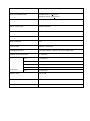
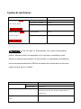
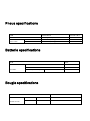
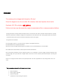
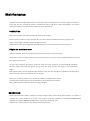
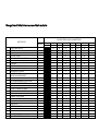
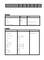
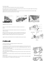
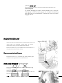
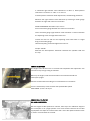
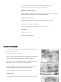
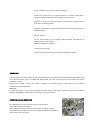
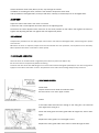
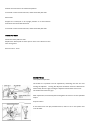
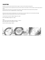
IMPORTANT Manuel d’utilisateur en cours de modification/traduction Pour toutes informations contactez-nous via le formulaire dans la rubrique contact de notre site internet. CHER CLIENT ASIAWING - Permettez-nous de vous féliciter sincèrement d’avoir porté votre choix sur une moto ASIAWING. Elle vous apportera beaucoup de plaisir si vous appliquez correctement les instructions de maintenance et d’entretien. Attention cependant toutes les informations du présent document sont fournies sans aucun engagement. Sous réserve de modifications, de suppression sans substitution ou d’adaptation aux in exigences locales des informations techniques, des tarifs, ainsi que d’un arrêt de fabrication définitif d’un modèle donné sans avis préalable ni indication d’un motif quelconque par la société ASIAWING. Maintenance Le respect des travaux de maintenance, d’entretien et de réglage du moteur et de la partie-cycle figurant dans le présent manuel d’utilisation constitue la condition préalable au parfait fonctionnement de la moto et permet d’éviter l’usure précoce. Un réglage incorrect de la partie-cycle risque d’entraîner des dégâts sur cette dernière ou la rupture de composants. Une utilisation de la moto dans des conditions extrêmes, telles que sur les pistes, un terrain très boueux ou détrempé, risque d’entrainer une usure plus importante de composants comme la chaîne ou les freins. De ce fait, il est possible que certains travaux de maintenance n’ait été atteinte. De plus respecter les temps de rodage ainsi que les intervalles de contrôle et de maintenance, prolonge de manière notable la durée de vie de la moto. Garantie La durée de garantie est de 1 ans hors compétition. Elle couvre le cadre les suspensions et le moteur, uniquement en usage hors compétition. Les travaux prévus dans le plan d’entretien doivent impérativement être réalisés par un concessionnaire ASIAWING agréé et doivent être confirmés dans le carnet d’entretien ou par une facture avec le numéro de série châssis. Le cas échéant, la garantie est annulée. La garantie peut être nul et non pris en charge en cas de dommages et conséquences résultant de manipulations et/ou modifications sur le véhicule. Transport Danger d’endommagement, si le véhicule en stationnement est susceptible de rouler accidentellement ou tomber. Il faut toujours stationner le véhicule sur un sol plan et stable. Remarque • Risque d’incendie pendant le fonctionnement, certaines parties du véhicule deviennent brûlantes. • Ne pas stationner la moto à proximité de matériaux facilement inflammables ou combustibles. Ne poser aucun objet sur la moto lorsqu’ il est chaud. Toujours attendre que la moto ait refroidi. • Arrêter le moteur. • Tourner le robinet d’essence en position OFF. Environnement Ce sport peut avoir des répercussions potentielles sur l’environnement et être source de conflits avec des tiers. Une utilisation responsable de la moto permet toutes fois d’éviter des problèmes et conflits. Pour ne pas mettre en danger l’avenir du sport moto, s’assurer que l’utilisation de la moto soit conforme à la loi et respecte l’environnement ainsi que les droits d’autrui. Fiche technique TE C H NI C A L D A TA I TE M O F FR O A D MO TA R D O V E R A L L L E N G TH 2175m m O V E R A L L WI D TH D I ME N S I ON S 810m m O V E R A L L H EI G H T 1240m m F /R W H E L L A XI S D I S - 1505m m TA N C E S EAT H E I G H T 960m m G R O UN D C L E A R AN C E 320m m N .W 118k g F R A ME TY P E A L U MI N IU M A L L OY F R ON T TI R E S IZ E 80/ 100-21 110/ 70-17 R EAR 1 1 0 / 9 0 - 1 9 ’’ 140/ 70-17 TIR E SI Z E F R ON T S U S P E N SI O N 130k g TWI N - S P AR I N V E R TE D C AR TR ID G E F O R K WI TH R E B O U N D C O MP R E S SI O N -D A MP I N G A DJ U S T R EAR SU S P E N SI O N MO N O S H O C K WI TH S P RI N G- P R E L O A D, R E - B O U N D A ND C O MP R E S S I ON - D A MP IN G AD - C H AS S I S J U ST F U E L TA N K C A P AC I TY 8 . 0 L WI TH R E S E R V E V A L V E TY PE SINGLE CY LINDER, 4-STROKE, LIQUID COOLED MA X POWER 32KW / 7500R PM : 4 3. 5 H P/ 7 5 0 0 R P M MOTEUR RATED POWER 3 0 . 5 K W / 7 0 0 0R P M COUPLE MAX 4 2 . 5 N M/ 6 5 0 0 R P M IDLE SPEED 1700±150 RPM CONSOMMATION ≤340 g/kW.h BORE X STROKE 96×62.1 mm DISPLACEMENT 449 ml COMPRESSION RATIO 11:1 VALVE TRAIN CHAIN DRIVE SOHC FOUR VALVE LUBRICATION TY PE PRESSURE SPRAY LUBRICATION OIL TY PE SAE 10W-40 IGNITION ADVANCE DEGREE 12°BTDC [3000RPM] VALVE CLEARANCE(COOL) INTAKE VALVE: 0.16+0.03 mm EXHAUST VALVE: 0.28+0.03 mm DECOMPRESS CLEARANCE EX VALVE CLEARANCE (0.28mm)+0.15mm=0.43mm SPARK DENSO IK24/IK27 PLUG TY PE DIMENSIONS 350mm×297mm×423 mm DRIVE TY PE CHAIN DRIVE SPROCKET 13T CLUTCH TY PE MANUAL, MULTI-WET TRANSMISSION TY PE CONSTANT MESH, 5 SPEED, LEFT FOOT OPERATED PRIMARY ADJUCTION RATIO 2.739(63/23) GEAR RATIO 1ST 2.230(29/13); 2ND 1.625(26/16) 3RD 1.235(21/17) 4TH 1.000(19/19) 5TH 0.826(19/23) IGNITION TY PE DC/AC CDI STARTER KICK / ELECTRIC STARTING CAPACITY ≤15 s Système de lubrification I TE M D A TA HUILE MOTEUR 8 7 0 m l API SG or higher A T D R A IN IN G 670 m l A T F I L TE R C H AN G E 700m l A T D I S A S S E MB L Y 870m l A T D R A IN IN G 850m l A T D I S A S S E MB L Y 9 0 0 m l ( Approx imately O n e Q u a r t ) S AE 1 0 W-4 0 HUILE DE BOITE 9 5 0 m l API SG or higher SAE 10W-40 ATTENTION : Low Oil level in Transmission can cause transmission failure. Warranty Void if transmission oil is not kept at mandatory level. Failure to change transmission oil and oil filter on scheduled maintenance and at recommended level of 950ml can cause the transmission to lock and cause serious injury or death. I TE M C O O L A N T C A P AC I TY D A TA AT C H AN G E 1. 11 lit er D I S A S S E MB L Y 1. 20 lit er A N TI FR E E Z E H I G H Q U A LI TY E THY L E N E G LY C O L A N TIF R E EZ E C O N TA I NI N G S I LI C A TE - FR E E C O RR O S I ON I N H I B I TO R S S TA N D A R D S C O O L AN T C ON C EN TR A TI O N 1 : 1 MI XTU R E WI TH D I S TI L L ED W A TE R Pneus specifications I TE M C O LD S TA N D A R D S TIR E PR E S S UR E MA X L O A D R E P A I R L I MI T 3 3 / 2 . 3 ( ps i / b a r ) F R ON T 430 / 1 9 5 ( l b s/ k gs ) R EAR 548 / 2 6 5 ( l b s/ k gs ) Batterie specifications I TE M B A TTE R Y D A TA C A P A C I TY 1 2 V - 6Ah C UR R E N T C ON S U MP TI O N MA X 0 . 1 m A V O L TA G E ( 2 0 0 / 6 8 0 F ) 13. 0-13. 2V F U LL Bougie specifications I TE M S PA R K P L U G D A TA S TA N D A R D S D EN SO I K24 O P TI O N A L N GK I FR 8 H - 1 1 INSPECTION AVANT UTILISATION Inspection Item Inspection Objective Engine oil Inspect for proper f ill lev el Huile de boite a vitesse Inspecter pour le bon niveau(900ml) Coolant Inspect for proper f ill lev el Fuel Be sure there is enough fuel to ride planned distance Cooling system Inspect for leaks, cracks, and fluid f low Check f or free travel of throttle grip and that the throttle grip has a smooth Throttle operation and in both the forward and back to the closed position Clutch Adjust the clutch cable to fully disengaged Steering Be sure the bars move freely from lock to lock and steering head is tight Brake Inspect for free travel of pedal and lever and that there is full braking power Tire Check tire pressure and inspect tires for cracks Spokes Inspect and tighten loose spokes if necessary Other Bolts and Parts Inspect attachment points and other bolts to ensure they are tight Exhaust muffler Inspect for loose bolts and the exhaust is secure RODAGE The motorcycle is shipped with break in Oil onl y! Once the engine is run for an initial 30 minutes, drain and replace the oil with: Synthetic API SG or higher SAE 10W-40 Failure to do so may decrease the engine transmission life or cause premature failure. During initial break-in newly machined surfaces will be in contact with each other and these surfaces will wear in quickly. Break-in maintenance at 150km is designed to compensate for this initial minor wear. Timely performance of the break-in maintenance will ensure optimum service life and performance from the engine. The general rules as follows: Start the engine and let it run at idle until the engine is thoroughly warmed up. Avoid full-throttle starts and rapid acceleration. Maximum continuous engine speed during the first 150km must not exceed 5,000 rpm (or 10 hours Max) After 150km ride maintenance the machine per the maintenance schedule. After the break-in procedure has been properly carried out, the motorcycle is ready for regular operation. However, since premature high r/min (rpm) will lead to engine trouble, take care to use the necessary skill and technique in operating the motorcycle. Never run the engine with full throttle at low speed operation. This rule is applicable not only during break-in but at all times. This procedure should be followed each time: Piston is replaced Piston rings are replaced Cylinder is replaced Crankshaft or crank bearing are replaced Maintenance The Maintenance Schedule specifies how often you should have your motorcycle served, and what things need attention. It is essential that your motorcycle be served as scheduled to retain its high level of safety, dependability, and emission control performance. Remember, proper maintenance is your responsibility. PR ECAUTION Make sure the engine is off before you begin any maintenance or repairs. Exhaust contains poisonous carbon monoxyde. Be sure there is adequate ventilation whenever you operate the engine. Let the engine and exhaust system cool before touching Be careful when working around gasoline. Keep cigarettes, spark, and flames away from all fuel related parts Règles de maintenances Place the motorcycle on the firm level ground using optional work stand or equivalent support Use genuine or recommend part and lubricants or other equivalents. Parts that do not meet design specifications may cause dam- age to the motorcycle Use only metric tools when servicing the motorcycle, metric nuts, bolts, screws are not interchangeable with British fasteners. Always replace with new gaskets, O-rings, cotter pins, piston pin clips, snap rings, etc after disassemble engine When tightening bolts and nuts, begin with larger diameter or inner bolt first. Then tighten to specified torque diagonally in incre-mental steps unless a particular sequence is specified. Clean parts in cleaning solvent upon disassembly, lubricate and sliding surface before assembly. Always inspect all parts for proper installation and operation after reassemble Route all electrical wires, cables and harness routing as designed. ENTRETIEN Required maintenance schedule is based upon average riding condition. Sustained high speed operation, or operation in unusually wet or dusty conditions, will require more frequent service than specified in the REQUIRED MAINTENANCE SCHEDULE. See SPECIA L MAINTANCE SCHEDULE for competition maintenance need. Perform the Pre-ride inspection at each scheduled maintenance period Symbol in maintenance schedule means: I Verifier et, laver,si necessaire lubrifier remplacer . C Laver R Remplacer A Ajuster L Lubrifier * Unless the rider is mechanically qualified and has proper tools, see authorized dealer for service ** Special maintenance strongly recommend to look for authorized dealer service. NOTE1. Clean after every ride for dusty conditions NOTE2. Replace every 2 years. Replacement requires mechanical skill NOTE3. Replace after the first break-in ride NOTE4. Inspect after the first break-in ride NOTE5. Replace the transmission oil once change the clutch plate Required Maintenance Schedule ENTRETIEN EN KILOMETRES ARTICLES NOTE * HUILE MOTEUR * FILTRE A AIR HUILE DE BOITE FILTRE A AIR RADIATOR COOLANT * JEU AU SOUPAPES BOUGIE ** FILTRE A ESSENCE * CABLE DE GAZ * POIGNEE DE GAZ SYSTÈME DE REFROIDISSEMENT SECONDARY AIR SUPPLY DECOMPRESSOR SYSTEM ENGINE IDLE SPEED DRIVE CHAIN DRIVE CHAIN SLIDER ENGINE IDLE SPEED BRAKE PAD WEAR BRAKE SYSTÈME HEADLIGHT FOCUS * EMBRAYAGE BEQUILLE * SUSPENSIONS SILENCIEUX VISSERIE ROUES/PNEUS * ROULEMENTS CHASSIS heures 10 km 150 1500 3500 6000 9000 12000 15000 R R R R R R R R R R R R I I I I R R R R R I R C I I R R R R I I I I I R C I I I I I I I I I I I I,L I I I I I I I I I I I I I I I I,L I I I I I I I I I I I I I I I I,L I I I I I I I I I I I I I I I I,L I I I I I I I I I I I I I I I I,L I I I I I I I I I I I I I I I I,L I I I I I I I I I I I I I I I I,L I I I I I I I I I I I I I I I SPECIAL ENTRETIEN ENDURO FREQUENCY About About About About About ITEMS 2.5hs 7.5 hs 15hs 22.5hs 30hs THROTTLE OPERATION I START SY STEM I NOT E AIR FILTER (NOTE1) C CRANKCASE BREATHER I SPARK PLUG I RADIATOR COOLANT (NOTE2) COOLING SY STEM I I VALVE CLEARANCE/DECOMPRESSOR (NOTE4) ENGINE OIL (NOTE3) ENGINE OIL FILTER (NOTE3) I I R R TANSMISSION OIL I ENGINE IDLE SPEED I R PISTON AND RING R PISTON PIN R DRIVE CHAIN I,L DRIVE CHAIN SLIDER I DRIVE CHAIN ROLLER I DRIVE/DRIVEN SPROCKET I BRAKE FLUID (NOTE2) I BRAKE PADS WEAR I BRAKE SY STEM I CLUTCH SY STEM (NOTE5) I CONTROL CABLES I,L EXHAUST PIPE/ MUFFLER I SUSPENSION I SWING ARM/SHOCK LINKAGE FORK TUBE/SLIDER FORK OIL DAMPER R L (NOTE3) R R NUTS . BOLTS. FASTENERS I WHEELS / TIRES I STEERING HEAD BEARINGS I MOTEUR ITEM CAUSE REMARK Cylinder head gasket Compression leak Replace whenever disassembled Wear or discoloration Leakage Clutch disc Damage Cylinder gasket Replace whenever disassembled Right crankcase cover gasket Replace whenever disassembled CHASSIS ITEM CAUSE REMARKS Front / rear tire wear Minimum knob height:8mm Front / rear brake pad wear Minimum thickness:1mm Sub-frame mounting bolts Fatigue or damage Wear Chain guide plate or damage Damage Damage Side cover Damage Front number plate Front / rear f ender Free play or damage Clutch lever / holder Free play or damage Brake lever Free play or damage Air throttle lever Free play or damage Bends Handlebar Damage Throttle housing Damage Grip rubber Damage pedal Damage Gearshift Brake pedal Chain adjuster / bolt Air cleaner Damage or cracks NOTE: These parts and their possible replacement schedule are based upon average riding conditions. Machines subjected to severe use require more frequent servicing. SYSTÈME DE CARBURATION Inspect the fuel line for damage or leak, if necessary replace fuel line. FILTRE A ESSENCE Remove the fuel tank. Drain the gasoline into a container and remove the fuel line, nuts ,and the clamps. Wash the fuel filter and reinstall the O-ring and reinstall components onto the fuel tank. Reinstall the fuel tank on the motorcycle . Make sure the tank does not leak. THROTTLE OPE RATION Check for smooth throttle grip at full opening and automatic full closing in all steering positions. Check the throttle cable and replace them if they are deteriorated, kinked or damaged. Lubricate the throttle cable if throttle operation is not smooth. Measure the free play at the throttle grip flange. FREE PLAY 3 -5mm(1/ 8-3/ 16in) Throttle grip free play can be adjusted at either end of the throttle cable. Minor adjustments are made with the upper adjuster. Remove the dust cover from the adjuster. Adjust the free play by Loosening the lock nut and turning the adjuster. Tighten the lock nut after making the adjustment. Reinstall the dust cover and recheck the throttle operation. Major adjustments are made with the carburetor end of cable. LEVIER STARTER FREE PLAY: 2-3 mm(1/8 -3/1 6in) Check for smooth choke lever operation and lubricate the cable if required. Inspect the cable for cracks which could allow moisture to enter. Replace the cable if necessary. Measure the choke lever free play at the lever end. Choke lever free play can be adjusted at the choke cable. Remove the dust cover from the ad- juster. Adjust the free play by loosening the lock nut and turning the ad- juster. Tighten the lock nut. Reinstall the dust cover. Recheck the free play at the lever. FILTRE A AIR Loosen the air cleaner retaining bolt. Remove the air filter. Remove the air filter from the holder. Thoroughly wash the air filter in clean non-flammable or high flash-point cleaning solvent. Then wash the element again in a solution of hot water and dishwashing liquid soap. Clean the inside of the air cleaner housing. After cleaning, be sure there is no dirt or sand trapped between the inner and outer layer of the cleaner. Wash again if necessary. Allow the air cleaner to dry thoroughly. After drying, soak the air filter in clean Foam Filter Oil or an equivalent. Apply air filter oil to the entire surface of the air filter and rub it with both hands to saturate the element with oil. Gently squeeze out excess oil. It is important not to over oil or under oil the element. Apply a thin coat of grease or an equivalent to the sealing surface. Assemble the air filter and the holder .Slip the air cleaner retaining bolt through the assembly. Tighten the retaining bolt securely. NOTICE : If the air filter assembly is not installed correctly ,dirt and dust may enter the engine resulting in wear of the piston ring and cylinder. CRAN KCA SE BREATHER Remove the breather hose drain plug, then drain any fluids or dirt from the hose into a proper container. Reinstall the drain plug. SPARK PLUG REMOVAL Remove the fuel tank and disconnect the spark plug cap. Remove The spark plug and inspect it for damage Clean around the spark plug base with compressed air before removing and be sure that no debris is allowed to enter the combustion chamber. INSPECTION Check the following and replace if necessary: 1) insulator for damage 2) electrodes for wear 3) burnt or discoloration If the electrode is contaminated with accumulated debris or dirt replace the spark plug. (this motorcycle’s spark plug is equipped with an iridium center electrode. Re- place the spark plug if the electrode is contaminated.) Replace the plug if the center electrode is rounded as shown in the picture. (Always use the specified spark plugs on this motorcycle) RECOMMENDED SPARK PLUG (OR EQUIVALENT) Standard: DENSO: IK24 Optional : DENSO: IK27 Check the gap between the center and side electrodes with a wire Type feeler gauge (To prevent damaging the iridium center electrode, use a wire type Feeler gauge to check the spark plug gap. Do not adjust the spark Plug gap if the gap is out of specification , replace with a new one.) Spark plug gap: 0.4 mm RADIATOR COOLANT Inspect the level of the radiator coolant should be between “upper” and “lower” when the motorcycle running under the normal temperature. If need , put recommended coolant fluid in: Remove the radiator cap . Put standard coolant concentration 1:1 to the upper line and then reinstall the cap. Recommended antifreeze Professional coolant or an equivalent high quality ethylene glycol antifreeze containing silicate free corrosion inhibitors. COOLING SYSTEM Remove the radiator grills. Check the radiator air passage for clogs or damage. Inspect the hoses for cracks and deteriorations. Use low pressure water and a soft brush to wash off any dirt that may be stuck in the radiator core. Replace if necessary. Check the tightness of the hose clamps and radiator mounting bolts. VALVE CLEANCE / DECOMPRESSOR SYSTEM VALVE CLEARANCE INSPECTION Inspect and adjust the valve clearance while the engine is cold (below 35℃/950 f) Remove the cylinder head cover. Remove the crankshaft hole cap and O-ring. Turn the crankshaft clockwise to align the punch mark with the index mark on the right crankcase cover. Make sure the piston is at TDC (Top Dead Center) on the compression stroke. Check that the index line on the cam sprocket aligns with the ”△” mark on the cam holder. SOUPAPE D’ADMISSION JEU: Insert the feeler gauge between the valve lifter and the cam lube. Check the valve clearance for the intake valves using a feeler gauge. Valve clearance IN: 0 .16+ 0.0 3mm SOUPAPE D’ÉCHAPPEMENT JEU: Insert the feeler gauge between the rocker arm and shim. Check the valve clearance for the exhaust valves using a feeler gauge. Valve clearance Ex: 0.28+0 .03mm VALVE CLEARANCE ADJUSTMENT: Remove the camshaft holder assembly The shims my stick to the inside of the valve lifter. Do not allow the shims to fall into the crankcase. The shims can be easily removed with tweezers or a magnet. Clean the valve shim contact area in the valve lifter with compressed air. Measure the shim thickness and record it. Seventy-three different shim series are available from 1.2000m m to 3. 000m m in intervals of 0.025mm. Calculate the new shim thickness using the equation below: A=(B-C)+D A: new shim thickness B: recorded valve clearance C: specified valve clearance D: old shim thickness Make sure of the correct shim thickness by measuring the shim using a micrometer Reface the valve seat if carbon deposits result in a calculated dimension of over 3.000mm. Install the valve lifters into the camshaft holder assembly. Install the camshaft holder assembly With the valve clearance adjusted, check and adjust the decompressor clearance Reinstall the cap and hand tighten, then torque to specification. Torque: 15N .m(1.5kgf, 11 lbf.ft) DECOMPRESSOR CLEARANCE INSPECTION / ADJUSTMENT: Inspect and adjust the decompressor clearance while the engine is cold (below 350 C/950 F) Remove the crankshaft hole cap. Turn the crankshaft clockwise to align the punch mark with the index mark on the right crankcase cover. Make sure that the piston is at Top Dead Center on the compression stroke. Measure the decompressor arm clearance by inserting a feeler gauge between the decompressor arm adjusting screw and right side rocker arm. DECOMPRESSOR CLEARANCE: RIGHT SIDE EXHAUS T VALVE C LEARANCE+ 0.15 mm EXAMPLE: If measured right exhaust valve clearance is 0.28m m, decompressor clearance is: 0.28mm +0. 15m m =0 .43 mm If decompressor clearance needs adjustment, see following procedure. Measure the right exhaust valve clearance by inserting a feeler gauge between the right side rocker arm and shim. VALVE CLEARANCE: EX:0.28m m±0. 03m m Pull out the feeler gauge between the rocker arm and shim Insert the feeler gauge (right exhaust valve clearance +0.15mm between the adjusting screw and right side rocker arm. Loosen the lock nut and turn the adjusting screw until there is a slight drag on the feeler gauge. Hold the adjusting screw and tighten the lock nut. Couple: 10N.M Recheck the decompressor clearance. Reinstall the cylinder head and the cap. ENGINE IDLE SPEED The engine must be warm for an accurate idle inspection and adjustment. Ten minutes of stop and go riding is sufficient. Warm up the engine, shift the transmission into neutral and hold the motorcycle upright. Connect a tachometer according to its manufacturer’s instructions. Turn the throttle stop screw to obtain the specified idle speed. IDLE SPEED: 1, 500 +10 0 rpm ENGINE OIL / OIL FILTER OIL LEVEL INSPECTION Run the engine at idle speed for 3 minutes, then stop it for 3 Minutes. Support the motorcycle in an upright position on a level surface. Remove the oil filter cap/dipstick and wipe the oil with clean cloth. Insert the dipstick without screw in, take it out and check the oil level. If the oil level is lower or near the lower level line on the stick, add Recommended oil to the upper level line through the hole. Reinstall the engine oil filter cap (Other viscosities shown in the chart may be used when the average temperature in your riding area is within the indicated range) RECOMMENDED ENGINE OIL: HP4M (with molybdenum additives) 4-stroke oil, or equivalent motor oil API service classification: SG or higher JASO T 90 3 STANDARD: MA or M B, viscosity: SEA 10 W - 40 OIL CAPACITY 0 .67liter at draining 0 .70liter at oil filter change ENGINE OIL & FILTER CHANGE Run the engine for 3 minutes. Stop the engine for 3 minutes and remove the oil filter cap. Remove the left side engine guard. Place an oil pan under the engine to catch the oil and remove the engine oil drain bolt and sealing washer to drain the engine oil. Operate the kick starter pedal several times while pushing the engine stop switch, so the engine oil completely drains. Remove the bolts and oil filter cover. Remove the oil filter and spring. Install the engine oil drain bolt with a new sealing washer. Tighten the engine oil drain bolt to the specified torque. TORQUE: 16N.m Apply grease to the filter side of the spring end. Install the spring into the oil filter as shown. Install the oil filter with the “OUT SIDE” mark f acing out. Installing the oil filter backwards will result in severe engine damage. Apply engine oil to a new O-ring and install it to the oil filter cover. Install the oil filter cover and tighten the bolt to the specified torque. Fill the engine with the recommended engine oil and Install the oil filter cap. Start the engine and let it idle f or a few minutes. Stop the engine and recheck the oil level and check f or leaks. Install the engine left side guard ENGINE OIL CAPACITY: 0.67 litre at drain 0.70 litre at change TRANSMISSION OIL CHE CKING OIL Run the engine at Idle for 3minutes, turn off engine and wait 3 minutes. Support the motorcycle on a level surface and remove the transmission oil filler cap, engine check bolt and sealing washer from the right crankcase cover. A small amount of oil should flow out of the check bolt hole. If no oil flow out, fill with recommended transmission oil through fueling hole until it can flow out of the hole. Reinstall the oil check bolt and engine oil filler cap. Repeat steps above After checking the oil level or filling, install the oil check bolt with a new sealing washer, tighten the oil check bolt and oil filler cap. CHANGING ENGINE OIL Run the engine to let it get hot before draining oil. Support the motorcycle in an upright position on a level surface and remove the engine oil filler cap from the right crankcase cover Place an oil drain pan under the engine to catch the oil. Then remove the drain bolt and sealing washer. After the oil has drained, install the drain bolt with a new sealing bolt to the specified torque Couple: 22N .M Fill the recommend oil to the engine. Recommended transmission oil: APLGL Viscosity: SAE 10w-40 Capacity: 0.85 liter at draining 0.900 liter at removing Inspect the oil level as the steps of oil level checking procedure. DRIVE CHAIN The drive chain must be checked, adjusted, and lubricated in accordance with the Maintenance Schedule. If the chain becomes badly worn or maladjusted, being either too loose or too tight the chain could jump off the sprockets or break. Under severe usage, or when the vehicle is ridden in unusually dusty or muddy areas, more frequent maintenance will be necessary. WARNING: A chain that breaks or jumps off the sprockets could snag on the engine sprocket or lock the rear wheel, severely damaging the motorcycle and causing it to go out of control. DRIVE CHAIN SLACK INSPECTION Turn the engine off, raise the rear wheel off the ground by placing the optional work stand. (Don’t inspect and adjust the drive chain when the engine running) Check slack in the upper drive chain run midway between the sprockets. Drive chain slack: 2 5-3 5mm Notice: Excessive chain slack (50mm/2.0in) may damage the vehicle. In addition to checking the slack, rotate the rear wheel to inspect the drive chain and sprockets for damaged rollers, loose pin and links, unevenly or excessively worn or damaged teeth. ADJUSTMENT Adjust the chain if the slack is too much or too little. Loosen the axle nut and adjuster lock nuts and turn the adjusting bolts. Check that the chain adjuster index marks are in the same position on both sides, then tighten the axle nut.. Tighten the adjusting bolt lock nut against the axle adjustment plates. REPLACEMENT If adjustment procedure can not apply proper chain slack or the chain has damaged rollers, loose fitting links, replace with new one. Whenever the chain is replaced, inspect both the countershaft and rear sprockets, and replace them if necessary. Worn sprockets will cause a new chain to wear quickly. CLEANING AND LUBRICATION Clean the chain in non-flammable or high flash-point solvent by soft brush. Wipe it dry. Be sure the chain is completed dry before lubricating. Lubricate the drive chain with #80-90 gear oil or drive chain lubricant designed specifically for use with O-ring chains. Apply oil to the side of the rollers so that it will penetrate to the rollers and bushings. Wipe off any excess oil. DRIVE CHAIN SLIDERS Chain slider Inspect the drive chain slider for excessive wear. Service limit: 5.0 mm from upper surface Notice: If the chain slider becomes worn though to the swing arm, the chain will wear against the swing arm. Check the chain guide and chain guide slider for alignment, wear or damaged. Replace the chain guide if it is damaged or worn. Replace the chain guide slider if the chain is visible through the wear inspection window. DRIVE CHAIN ROLLER Inspect the drive chain roller for excessive wear or binding. Service limit : Mini mum roller O.D: Upper: 39m m/Lower: 35 mm Replace the roller if necessary, and tighten the roller bolt/nut to the specified torque. (The sign”→” means installing the drive chain roller outside) Torque: Upper bolt: 12N. m Lower nut: 1 2N.m DRIVE/DRIVEN SPROCKETS Inspect the drive and driven sprocket teeth for wear or damage and replace if necessary. Do not install the new drive chain on worn sprocket. The chain and sprockets must be in good condition, or the new chain will wear rapidly. Inspect the bolts and nuts on the drive and driven sprockets. Tighten them when they become loosened. Torque: Drive sprocket bolt: 31N.m Driven sprocket nut: 32N .m BRAKE FLUID Notice Avoid spilling fluid will damage the plastic or rubber parts. Place a rag over these parts whenever the system is serviced. Do not mix different types of fluid, as they are not compatible with each other. Do not allow foreign material to enter the system when filling the reservoir. Fluid level inspection When the fluid level is low, check the brake pads for wear. A low fluid level may be due to wear of the brake pads. If the brake pads are worn, the caliper piston is pushed out, and this accounts for a low reservoir level. If the brake pads are not worn and the fluid level is low, check the entire system for leaks. Front brake Position the site level in the horizontal position. If the level is near the low level line, check the brake pad wear. Rear brake Support the motorcycle in an upright position on a level surface and check the rear brake fluid level. If the level is near the low level line, check the brake pad wear. BRAKE PAD WEAR Check the brake pads for wear. Replace the brake pads if either pad is worn to the bottom of the wear limit groove. Service limit: 1. 0mm BRAKE SYSTEM Level position inspection The brake lev el position can be adjusted by loosening the lock nut and turning the adjuster. Turning the adjuster clockwise moves the brake lever farther away from the grip; turning the adjuster counterwork wise moves The brake lever closer the grip. After adjustment, hold the adjuster and tighten the lock nut to the specified torque. Torque: 5.9N.m If the brake lever free play exceeds 20mm, there is air in the system that must be bled. Brake pedal height Adjust the brake pedal to the desired height by loosening the lock nut and turning the pedal height adjusting bolts. Standard height: 79.6mm Tighten the lock nut to the specified torque Couple: 5.9N.m SWINGARM/SHOCK LINKAGE Raise the rear wheel off the ground by placing a work stand or equivalent under the engine. Check for worn swing arm bearings by grabbing the rear swing arm and attempting to move the swing arm side-to -side. Replace the bearing if excessively worn. Check the shock linkage and replace any damaged needle bearings. Disassemble, clean, and inspect the swing arm and shock linkage pivot bearing and related seals every three races or about 7.5 hours of operation. ROUES/PNEUS Support the frame by the bracket under the engine, so that the front wheel off the ground. Grab the bottom of front suspension and rock the front wheel on both sides to check whether the front wheel axle is loose. Grab the rocker and rock the rear wheel on both sides to check whether the rear wheel axle has problem. Check the tires for cuts, embedded nails, or other damage. Check the cold tire pressure (Remember to do it when the tire is cold). Check the rims and spoke for damage. Tighten all the loose wheel spokes and lock (valve nut) Torque Specs Tire pressure Front wheel :98kPa(1.0kgf/cm2 ,14psi) Rear wheel:98kPa(1.0kgf/cm2 ,14psi) Tools: Torque Front wheel spoke:3.68N.m(0.4kgf. m,2. 7lbf.ft) Rear wheel spoke:3.7N.m(0.4kgf.m,2 .7lbf.ft) Valve nut:13N.m(1.2kgf.m, 9lbf.ft) SHANDONG ASIAWING MOTORS CO.,LTD Address:Taian City, Shandong Province PC:271000 Tel:0538-6366706/6366708 Fax:0538-6366702