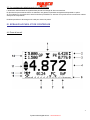
1
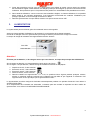
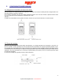
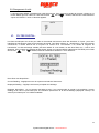
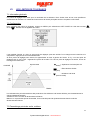
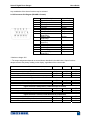
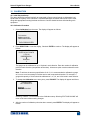
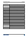
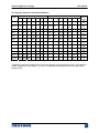
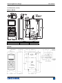
Contrôle de dureté des
métaux et élastomères
Rugosimètres, Vidéo 2D
Projecteurs de profils
Dinamomètre DIGITAL
Série 5
Manuel d'Utilisation
Microscope loupes
systèmes optiques
Mesure des forces
Pesage
Instrumentation
Mesure à main
Niveaux électronqiues
www.someco.fr
Page sur 16
2
Dynamomètre digital série 5 - www.someco.fr
Nous vous remercions d’avoir choisi notre DYNANOMETRE
DIGITAL SERIE 3 MARK 10 conçu pour évaluer la force de
compression et de traction de 0.5 N à 2500N à pleine échelle.
SERIE 3 est un composant essentiel d’un système de test de
force, il peut-être couplé à un banc d’essais, une pince de
préhension, et un logiciel de collecte de données.
Avec l’utilisation appropriée, vous obtiendrez de nombreuses
années de bon service grâce à ce produit.
Le DYNANOMETRE MARK 10 est de construction robuste pour
garantir de nombreuses années de service dans les laboratoires
ou les industries.
Ce manuel d’utilisation fournit les instructions à suivre afin
d’utiliser votre appareil, ainsi que les règles de sécurité à prendre
en compte.
Les dimensions et les caractéristiques sont aussi fournies. Si
vous avez des questions, n’hésitez pas à nous contacter, notre
service technique et notre équipe d’ingénieurs seront ravis de
vous aider.
Avant toutes utilisations, toute personne qui utilise le
DYNANOMETRE MARK 10 devra être formé aux règles de
sécurité et à l’utilisation de l’appareil.
TABLE DES MATIERES
VUE D’ENSEMBLE
4
CAPACITES
4
CONFIGURATION MECANIQUE
6
ECRAN D’ACCUEIL ET COMMANDES
7
MODE OPERATOIRE
10
CHANGER LES UNITES
13
FILTRE DIGITAL
13
LES LIMITES DE TOLERANCE
14
Page sur 16
3
Dynamomètre digital série 5 - www.someco.fr
I.
VUE D’ENSEMBLE
1.1 Listes d’articles inclus.
Description
Mallette de transport
Chargeur
Accumulateur (dans le dynamomètre)
Rallonge
Embout conique
Embout biseauté
Embout en V
Embout plat
Embout crochet
Raccordement
Certificat de calibration
Câble USB
CD (pilotes et manuels)
1.2 Règles de sécurité.
Attention !
Vérifier les capacités du dynamomètre avant l’utilisation et assurez vous que celles-ci ne dépassent pas la
limite.
Une surcharge de plus de 150% de la capacité du dynamomètre peut endommager la cellule de charge
interne.
De nombreux matériaux peuvent être testés avec ce dynamomètre. Les instruments ne doivent pas être utilisés avec
des substances ou produits potentiellement inflammables, les articles peuvent se détruire et provoquer des risques.
Les règles de sécurité et les procédures à suivre avant et pendant l’opération :
1. Ne jamais toucher le dynamomètre si il y a des dégâts visibles sur le chargeur.
2. Assurer vous, à tout moment, que le dynamomètre est gardé loin de l’eau ou d’autres liquides électriquement
conducteurs.
3. Le dynamomètre doit être manipulé par un technicien formé. Le chargeur doit être déconnecté et le
dynamomètres peut être éteins.
4. Toujours considéré les caractéristiques de l’échantillon avant de faire un test. Une évaluation de risque
devrait être effectuée à l’avance pour assurer que toutes les mesures de sécurité ont été adressées et mises
en œuvre.
Page sur 16
4
Dynamomètre digital série 5 - www.someco.fr
5. Porter des protections pour les yeux et le visage quand vous utilisez le produit, surtout quand vous utilisez
des échantillons fragiles. Faites attention aux dangers posés par les énergies qui peuvent s’accumuler durant
l’utilisation. Des protections pour le corps doivent être portées car une défaillance est possible durant un test
6. Dans certaines utilisations, comme un test sur des échantillons fragiles, ou d’autres utilisations, il est possible
d’être amené à une situation dangereuse, il est fortement recommandé de cartériser l’installation pour
protéger l’opérateur et son entourage de tessons ou débris.
7. Quand le dynamomètre n’est pas utilisé, assurez vous que le bouton soit sur OFF.
II.
ALIMENTATION
Le dynamomètre peut fonctionner grâce à une batterie interne rechargeable.
Après une longue période d’utilisation ou de stockage, il est nécessaire de recharger la batterie.
Connecter le chargeur fourni au dynamomètre (voir image ci-dessous) et brancher le chargeur au secteur.
Le temps de charge de la batterie sera approximativement de 8heures.
Port USB
Attention !
N’utilisez pas de batteries, ni de chargeur autres que ceux fournis, au risque de provoquer des défaillances.
Si le chargeur est branché, un icône apparaît en bas à gauche de l’écran :
Si le chargeur n’est pas branché, l’état de charge de la batterie se divise en cinq étapes :
1.
2.
3.
4.
5.
Supérieure à 75%, l’icône est ainsi :
Entre 50% et 75%, l’icône est ainsi :
Entre 25% et 50%, l’icône est ainsi :
Inférieure à 25%, l’icône est ainsi :
Quand la batterie est approximativement à 2%, le quatrième icône clignote pendant quelques minutes,
ensuite un message apparaît, indiquant que la batterie est trop faible et que l’appareil va s’éteindre. Puis
l’appareil émet un son qui indique que le dynamomètre s’éteint.
Le dynamomètre peut être configuré à s’éteindre automatiquement pendant une période d’inactivité. Vous referez à
AUTRES REGLAGES
Si le remplacement de la batterie est nécessaire, la batterie peut être accédé en séparant les deux moitiés du
dynamomètre. Vous referez à CONFIGURATION MECANIQUE.
Page sur 16
5
Dynamomètre digital série 5 - www.someco.fr
III.
CONFIGURATION MECANIQUE.
3.1 Chargement d’orientation de l’axe de la cellule.
Afin de permettre une variété de tests plus importants, l’orientation de l’axe de la cellule peut être configuré dans l’une
des deux positions montrées ci-dessous.
Pour changer l’orientation de l’axe de la cellule, desserrez les deux vis sur le dos du boîtier, séparez les deux cotés
du boîtier, faites tourner de 180 degrés et rassemblez les cotés.
Attention !
Lorsque vous rassemblez les deux parties du boîtier, assurez vous que des fils internes ne s’immiscent pas.
Embout de Cellule en haut en haut
Embout de cellule en bas
3.2 Plaque de montage.
Bien que le dynamomètre puisse être utilisé manuellement, un montage approprié est nécessaire s’il est fixé à un
banc de contrôle. L’insert cylindrique au dos du boîtier permet de résister à une charge importante pendant un test.
Une goupille devra être utilisée (voir l’image ci-dessous). Le système de fixation MARK-10 inclus la goupille et quatre
trous taraudés sur le dos du boîtier. En option il est possible d’avoir deux trous supplémentaires pour insérer des vis
métriques. Ces trous permettent aux vis de fixer le dynamomètre (vis fournies.) Les vis ne doivent pas être utilisé
pour d’autres montages.
Un mauvais montage de la goupille pourrait s’avérer dangereux.
Dos du boîtier
Goupille
Plaque de montage
Page sur 16
6
Dynamomètre digital série 5 - www.someco.fr
3.3. Le montage des attachements du dynamomètre.
L’embout de cellule taraudé du dynamomètre permet le montage de divers accessoires.
En plus des cinq accessoires fournis en standard, une gamme importante est également disponible en option.
Si vous utilisez un accessoire d’un autre fournisseur que MARK-10, assurez vous qu’elle soit de construction robuste
ainsi que ces composants.
N’utilisez pas d’écrou de blocage ou d’outils pour serrer les prises.
IV. ECRAN D’ACCUEIL ET DE CONTROLES
4.1 Ecran d’accueil
Page sur 16
7
Dynamomètre digital série 5 - www.someco.fr
Tableau 1 :
Indicateurs de
compression
et tractions
Indique la direction de la compression.
Indique la direction de la traction.
Ces indicateurs sont dans le menu
2&
3
Peak
Permet de figer l’affichage de traction et compression. Ces mesures sont réinitialisé si on appuie sur
ZERO ou si on éteint l’appareil.
4
Lecture principale
5
Barre de charge
6
Unités
Les unités de mesures :
IbF = les livres
kgF = les kilogrammes
gF = les grammes
N = les Newton
Tous les dynamomètres ne possèdent pas toutes ces unités. Referez vous aux capacités du produit
dans SPECIFICATION
7
Mode
Les modes de mesures :
RT (Real time) = Affichage en temps réel.
PC = Peak de compression
PT = Peak de traction.
Referez vous dans MODE OPERATOIRE pour plus de détails sur les modes.
9
Batterie/ chargeur
L’icône de la batterie dépend de l’état de charge de l’appareil. Referez vous à CAPACITES pour plus de
détails
11
Tolérance
Correspond aux points de réglages programmés, les indicateurs sont :
= Supérieure à la limite.
= Entre les limites.
= Inférieure à la limite.
12
Point de réglage
Suivant les paramètres programmés, on peut avoir 1,2 ou aucun indicateur à l’écran.
8
10
Nbre de points
stocké
Témoin de sortie
de données
automatique
La force appliquée s’affiche à l’écran. Referez vous au MODE OPERATOIRE (p8), pour plus de détails.
L’indicateur permet d’aider à identifier si une condition de surcharge est imminente. La barre
augmente à droite ou a gauche du graphique. Si elle augmente à droite cela indique une charge de
compression, en revanche à gauche cela indique une charge de traction.
Si les point de réglages sont activés, des repères triangulaires s’affichent à l’écran.
Cet indicateur reflète le chargement actuel qui peut ne pas correspondre à la lecture principale (selon
les modes opératoires choisi). La touche ZERO ne réinitialise pas la barre de charge. Referez vous au
MODE OPERATOIRE pour plus de détails (p8)
Indique le nombre de données stockées dans la mémoire, jusqu'à 1000. Montré
seulement si On permet le Stockage de mémoire dans la clé de DONNÉES
Si on a permis la sortie Auto dans le paramétrage du port / USB, cet indicateur
est affiché. Quand la sortie de données automatique arrive, l'icône devient
animée. Voir la section de Communications pour des détails
Page sur 16
8
Dynamomètre digital série 5 - www.someco.fr
4.2 Contrôles
Touches
Fonction première
Touches
Fonction seconde
Appuyer sur cette touche pour allumer et
éteindre le dynamomètre
Permet de sélectionner. Différents menus ou
sous-menus
Remet à 0 le peak et le réinitialise.
Vers le haut entre menus et sous menus
Appuyer pour entrer dans le menu principal
Retourner en arrière dans le menu
Permet sélectionner les modes de mesure
(PC,RT, PT)
Vers le bas entre menus et sous menus
Stocke une valeur dans mémoire, transmet la
valeur lue à un dispositif externe, et-ou
amorce la sortie de données automatique,
selon la configuration. (Clé USB)
Change l’affichage pendant la calibration, et
bascule entre les directions de tractions et de
compressions en configurant les points de
réglages
Permet de basculer d’une unité vers une
autre
Active ou désactive le mode SUPPRIMER, tout
en regardant des données stockées.
Note : Les unités de mesures sont configurées dans le menu, referez à la colonne 6 du tableau 1 (Mode) pour plus de
détails.
4.3 L’essentiel pour naviguer dans le menu
La plupart des fonctions et des paramètres du dynamomètre se configure grâce au menu. Pour accéder au menu,
appuyez sur MENU. Utilisez les touches
UP (monter) et
DOWN (descendre) pour choisir le sous-menu
désiré, appuyez sur ENTER pour entrer dans le sous-menu, puis utilisez
UP et
DOWN pour choisir la
fonction à paramétrer, appuyez sur ENTER pour sélectionner cette fonction.
Pour sélectionner ou désélectionner des paramètres, appuyez sur ENTER. Un astérisme (*) s’affiche lorsque le
paramètre est sélectionné.
Pour les paramètres où il est nécessaire d’insérer des valeurs numériques, utilisez
UP et
DOWN pour
activer ou désactiver une valeur. En restant appuyé sur la touche, les valeurs s’incrémentent automatiquement.
Ensuite cliquer sur ENTER pour valider l’activation, puis revenez au menu principal grâce à la touche ESCAPE.
Referez vous au sections suivantes pour plus de détails.
Page sur 16
9
Dynamomètre digital série 5 - www.someco.fr
V.
MODE OPERATOIRE.
Attention !
Dans n’importe quel mode, si la capacité de l’appareil est dépassé de plus de 110%, l’écran affichera OVER afin
d’indiquer une surcharge de l’appareil. Une alerte sonore peut être activé dans le menu.
Trois modes opératoires sont possibles avec le dynamomètre SERIES 3, pour naviguer entre les modes, appuyez
sur MODE quand vous êtes à l’écran d’accueil.
5.1 (RT- Real time) Affichage en temps réel.
La lecture principale correspond à la mesure indiquée.
5.2 Peak de compression (PC)
La lecture principale correspond au pic de compression observée. Si la force décroît, la valeur maximale sera
enregistrée sur la lecture principale.
Pour réinitialiser la valeur, appuyez sur ZERO.
5.3 Peak de Traction/Cœfficient statique de friction (PT)
De même que pour le peak de compression, mais pour la compression
Pour le dynamomètre M5-2COF, la lecture dans ce mode représente le coefficient statique de frottement.
NB : Le coefficient statique est toujours représenté dans le coin juste supérieur de l'affichage par la tension
maximale
Valeur, indépendamment du mode d'exploitation
5.4 Mode moyenne/ Coefficient de frottement statique (AVG)
Le mode moyen est utilisé pour obtenir une force moyenne
durant une période indiquée de temps. Cette lecture
représente aussi le coefficient cinétique de friction dans le cas
du dynamomètre modèle M5-2-COF.
Les applications incluent la mesure de force de pelure, COF,
la force de muscle, la force frictionnelle et d'autres tests
exigeant des lectures moyennées de temps.
Avant que les paramètres de Mode Moyen ne peuvent être
configurés, on doit le permettre. Pour faire ainsi, choisir
Le mode Moyen du menu, le rouleau pour Permettre et
presser ENTRER. L'affichage apparaît comme suit :
Alors, se déplacer dans le paramétrage et appuyer ENTRER pour configurer les paramètres. Les paramètres sont
affichés comme suit :
Page sur 16
10
Dynamomètre digital série 5 - www.someco.fr
Paramètres
Temporisation initiale
Durée de la séquence de
moyennes
Force de déclenchement
Description
Départ différé, en second, avant le départ d’une séquence de moyennes
Durée, en secondes, de la séquence de moyenne
La force minimale exigée pour commencer l'ordre de pondération (séquence de
moyennes). Interrupteur à bascule entre compression et directions de tension en
appuyant sur la touche de DIRECTION. Le retard initial suit la force de
déclenchement.
Après que les paramètres ont été configurés et le menu a été quitté, presser la tocuhe MODE jusqu'à ce que
l'AVG (la MOYENNE) soit affiché. Alors presser ZÉRO. Le mode moyen est maintenant activé et l'ordre de
pondération commencera quand la force de déclenchement sera atteinte. Le statut actuel de l'ordre moyen est
affiché au-dessous de la lecture principale, comme suit :
Niveau
1
2
3
Abréviation du statut
TRIG WAIT
INIT DLY
AVERAGING
4
AVRG DONE
Description
La force de déclenchement n’est pas atteinte
La temporisation initiale est en cours
Le dynamomètre collecte les données. Le statut clignotera tant que la
pondération ne sera pas achevée.
La pondération est achevée. La force moyenne est affichée à l’écran
principale
À l'achèvement de l'ordre de pondération, les valeurs maximales sont conservées jusqu'à ce que le ZÉRO n’a pas
été appuyé.
Un autre ordre de pondération peut être commencé après que la touche ZÉRO aura été pressée. Pour quitter le
mode Moyen, presser MODE et sélection le mode de mesure désiré.
5.5 Coefficient poids frottement (pour M5-2-COF uniquement)
Le M5-2-COF exécute des calculs COF en divisant la force par le poids de frottement. Par exemple, une force de
100 gF divisés par 200 g égale 0.5 COF. Bien que beaucoup de COF le test de d'applications exige un poids de
frottement de 200 g, le dynamomètre permet à l'utilisateur de changer le poids de frottement pour respecter
d'autres exigences.
Modifier le poids de frottement, choisiraient COF du menu. L'affichage apparaît comme suit :
5.6 Déclenchement externe (ET)
Ce mode de fonctionnement est utile pour mesurer la force d'activation de contact électrique aussi bien que la
synchronisation d'instruments multiples pour une vue "instantanée" de forces appliquées. Il est possible de
capturer la lecture avec un contact normalement ouvert (haut à la transition basse du signal de déclenchement) ou
un contact normalement fermé (transitionbas vers haut du signal de déclenchement).
Avant que les paramètres de Mode de Détente Externe ne puissent être configurés, on doit le permettre. Pour
cela, entrez dans le menu principal, choisissez la DECLENCHEMENT EXTERNE, se déplacer dans le menu
déroulant et choisir l’une des options 1 à 4 et presser ENTRE.
Les options sont comme suit :
Page sur 16
11
Dynamomètre digital série 5 - www.someco.fr
Option
Ponctuelle Haut -> Bas
Ponctuelle Bas -> Haut
Haut maintenu
Bas maintenu
Description
L'affichage gèlera la lecture capturée jusqu'à ce que ZÉRO soit pressé. S'applique à
transition du signal de déclenchement d’une valeur haute vers une valeur basse.
L'affichage gèlera la lecture capturée jusqu'à ce que ZÉRO soit pressé. S'applique à
transition du signal de déclenchement d’une valeur basse vers une valeur haute.
L'affichage montrera la lecture capturée tant que le signal Haut est maintenu.
L'affichage montrera la lecture capturée tant que le signal Bas est maintenu.
Après que la sélection a été faite et le menu a été quitté, presser la touche MODE jusqu’à l’affiche « ET ».
Le mode de déclenchement Externe est maintenant actif. Référez-vous au diagramme de connexion dans la
section de Communications pour des informations de connexion.
Quitter le mode de déclenchement Externe, presser MODE et choississez le mode de mesure désiré.
NB : Lorsqu’on a activé le mode de déclenchement externe, il est toujours actif même si le dynamomètre est en
mode « temps réel ». Après les gels d'affichage, n'importe quels points d'ensemble programmés seront actifs.
Cependant, si la jauge est dans le mode de Déclenchement Externe, n'importe quels points d'ensemble
programmés seront inactifs.
5.7 Déclenchement externe, schéma
Page sur 16
12
Dynamomètre digital série 5 - www.someco.fr
5.8 Changement d’unité
Le dynamomètre SERIE 3 possède trois unités de mesures. Pour changer les unités de mesures, cliquez sur la
touche MENU puis sur UNITS, à l’aide des touches
UP et
DOWN, sélectionnez l’unité désirée et
cliquez sur ENTER. L’écran ci-dessous apparaît :
VI.
FILTRE DIGITAL.
Les filtres numériques sont inclus pour aider à l’exactitude des lectures dans des situations où il peut y avoir des
interférences mécaniques dans l’environnement de travail. Ces filtres utilisent un « amortisseur » pour des lectures
consécutives, a lecture affichée est la moyenne du contenu d’un « amortisseur ». En variant la longueur de
l’amortisseur, un effet de lissage variable peut être réalisé. Si vous mettez l’un des deux filtres sur 1, celui-ci sera
désactivé. Pour accéder aux réglages du filtre digital, cliquez sur la touche MENU, sélectionnez FILTERS puis à l’aide
des touches
UP et
DOWN, faites les modifications désirées. L’écran affichera :
Deux filtres sont disponibles :
Current Reading : s’applique au taux de capture maximale de l’instrument.
Displayed Reading : s’applique à la lecture principale de l’affichage.
Réglages disponibles : 1,2,4,8,16,32,64,128,256,512,1024. Il est recommandé de garder le d’acquisition (current
reading) à sa valeur la plus basse pour une meilleure performance et le filtre d’affichage (displayed current) à sa
valeur la plus haute pour une meilleure stabilité.
Page sur 16
13
Dynamomètre digital série 5 - www.someco.fr
VII.
LES LIMITES DE TOLERANCE.
7.1 Information générale
Les points de réglages sont utiles pour la vérification de la tolérance. Deux limites, haut et bas, sont spécifiés et
stockés dans la mémoire non-volatile de l’instrument et la lecture principale est donc comparée à ces limites.
7.2 Configuration
Pour configurer les points de réglages, cliquez sur MENU puis sélectionnez SET POINTS à l’aide des touches
UP et
DOWN, l’écran apparaît donc ainsi :
Il est possible d’activer un, deux ou aucun point de réglages, peut être activés. Pour changer entre la traction et la
compression, appuyez sur la touche DIRECTION.
Si deux points de réglages sont activés, ils apparaissent en haut à gauche de l’écran. Si il y a un seul point de
réglage activé, le mot « OFF » apparaît à la place de la valeur. Et si aucun point de réglage n’est activé, l’écran en
haut à gauche reste blanc.
= Supérieure à la limite (NO GO
CHARGE
HIGH)
= Entre les deux limites
(GO)
= Inférieure à la limite
(NO GO LOW)
TEMPS
Les indicateurs de point d'ensemble et des productions font référence à la lecture affichée, pas nécessairement la
charge instantanée actuelle.
Interactions avec le mode de déclenchement Externe
Même si on a permis des points d'ensemble, ils sont inactifs quand le dynamomètre est dans le mode de
déclenchement Externe.
7.3 Paramétrage points de sortie, schéma
Page sur 16
14
Dynamomètre digital série 5 - www.someco.fr
Page sur 16
15
Dynamomètre digital série 5 - www.someco.fr
7.4 Utilisation du paramétrage de points pour contrôler un banc motorisé ESM301
En utilisant le paramétrage de points de ARRET/CYCLE de déplacement du croisillon sur un stand ESM301, le point
paramétré supérieur doit toujours être une valeur dans la direction de tension et le point le plus bas doit toujours être
une valeur dans la direction de compression.
Les deux points paramétré doivent être mis, même si l’application destinée doit ARRET/CYCLE à seulement un des
points paramétré. Le point paramétré opposé devrait être une valeur suffisamment grande pour qu'il ne puisse pas
déclenché durant le test.
Sur certains bancs d’essais Mark, la traction et la compression sont inversées.
Page sur 16
16
Dynamomètre digital série 5 - www.someco.fr
Series 5 Digital Force Gauges
User’s Guide
7.4 Using Set Points to Control a Mark-10 ESM301 Motorized Test Stand
When using set points to stop/cycle crosshead motion on an ESM301 stand, the upper set point must
always be a value in the tension direction, and the lower set point must always be a value in the
compression direction. Both set points must be set, even if the intended application is to stop/cycle at
only one of the set points. The opposite set point should be a value sufficiently large that it does not get
triggered during the course of the test.
For certain other Mark-10 test stands, the tension and compression directions are reversed.
8 DATA MEMORY AND STATISTICS
Series 5 gauges have storage capacity of 1,000 data points. Readings may be stored, viewed, and output
to an external device. Individual, or all, data points may be deleted. Statistics are calculated for the data
presently in memory.
To enable memory storage, select DATA Key from the menu, then scroll to Memory Storage and press
ENTER. Then exit the menu. In the home screen, the data record number 0000 will appear below the
primary reading. Press DATA at any time to save the displayed reading. The record number will
increment each time DATA is pressed. If DATA is pressed when memory is full the message “MEMORY
FULL” will be flashed at the bottom of the display and a double audio tone will be sounded.
To view, edit, and output stored readings and statistics, select Memory from the menu. The screen
appears as follows:
MEMORY
View Data
View Statistics
Output Data
Output Statistics
Output Data & Stats
Clear All Data
8.1 View Data
All the saved data points may be viewed. The record number is displayed, along with the corresponding
value and presently set unit of measurement. Any readings may be deleted individually. To do so, scroll
to the desired reading and press DELETE. The letter “D” will appear to the left of the record number,
indicating that the gauge is in Delete mode, as follows:
0001
0002
0003
0004
D 0005
0006
0007
2.458 lbF
2.224 lbF
2.446 lbF
1.890 lbF
2.098 lbF
1.998 lbF
2.042 lbF
Press ENTER to delete the value. To exit Delete mode, press DELETE again. Any number of readings
may be individually deleted, however, all readings may also be cleared simultaneously. Refer to the Clear
All Data section for details.
8.2 Statistics
Statistical calculations are performed for the saved values. Calculations include number of readings,
minimum, maximum, mean, and standard deviation.
12
Series 5 Digital Force Gauges
User’s Guide
8.3 Output Data
Press ENTER to output data to an external device. The display will show, “SENDING DATA…”, then
“DATA SENT”. If there was a problem with communication, the display will show, “DATA NOT SENT”.
Saved data can be downloaded by some Mark-10 data collection programs. Refer to their respective
user’s guides for details.
8.4 Output Statistics
Press ENTER to output statistics to an external device. The display will show, “SENDING STATS…”, then
“STATS SENT”. If there was a problem with communication, the display will show, “STATS NOT SENT”.
8.5 Output Data & Stats
Press ENTER to output data and statistics to an external device. The display will show, “SENDING
DATA”, then “SENDING STATS…”, then “DATA SENT”, then “STATS SENT”. If there was a problem with
communication, the display will show, “DATA NOT SENT” and/or “STATS NOT SENT”.
8.6 Clear All Data
Press ENTER to clear all data from the memory. A prompt will be shown, “CLEAR ALL DATA?”. Select
Yes to clear all the data, or No to return to the sub-menu.
For output of data and/or statistics, RS-232 or USB output must be enabled. Data formatting is
<CR><LF> following each value. Units can be either included or excluded. Output of data via the Mitutoyo
output is possible, however, output of statistics is not. Refer to the Communications section for details.
Note: Data is not retained while the gauge is powered off. However, the gauge protects against
accidental or automatic power-off. If manually powering the instrument off, or if the inactivity time limit for
the Automatic Shutoff function has been reached, the following warning message will appear:
*** WARNING ***
DATA IN MEMORY
WILL BE LOST
CANCEL
POWER OFF
If no option is selected, this screen will be displayed indefinitely, or until battery power has been depleted.
9 COMMUNICATIONS
Communication with Series 5 force gauges is achieved through the micro USB or 15-pin serial ports
located at the bottom of the instrument, as shown in the illustration in the Power section. Communication
is possible only when the gauge is in the main operating screen (i.e. not in a menu or configuration area).
9.1 Installing the USB driver
Caution!
It is recommended that the USB driver be installed before physically connecting the tester to the
PC with a USB cable.
For installation instructions, refer to the Mark-10 USB Driver user’s guide, supplied on the Resource CD
or downloadable from www.mark-10.com.
9.2 Serial / USB
To set up RS-232 and USB communication, select Serial/USB Settings from the menu. The screen
appears as follows:
13
Series 5 Digital Force Gauges
User’s Guide
SERIAL/USB SETTINGS
* RS232 Selected
USB Selected
+ Baud Rate
+ Data Format
+ Auto Output
Select either RS-232 or USB input (output is always simultaneous through both the USB and RS-232
ports). RS-232 must be selected when communicating through a Mark-10 test stand controller. When
communicating from the gauge directly to a PC or data collector, either RS-232 or USB can be selected
as required. Press DATA to transmit individual data points or to commence an automatic output
sequence (see Automatic Output sub-section for details). Single point or continuous data may also be
requested via ASCII commands from an external device (see Command Set sub-section for details).
Communication settings are permanently set to the following:
Data Bits:
8
Stop Bits:
1
Parity:
None
Other settings are configured as follows:
9.2.1 Baud Rate
Select the baud rate as required for the application. It must be set to the same value as the receiving
device. When communicating with a Mark-10 test stand controller, the baud rate must be set to 9,600.
9.2.2 Data Format
Select the desired data format. The screen appears as follows:
*
DATA FORMAT
Numeric + Units
Numeric Only
Invert Polarity
Omit Polarity
Selection
Numeric + Units
Numeric Only
Invert Polarity
Omit Polarity
Description
Output format includes the value and unit of measure. Compression values have
positive polarity, tension values have negative polarity.
Output format includes the value only. Polarity same as above.
Compression values have negative polarity, tension values have positive polarity.
May be selected in addition to the Numeric + Units / Numeric Only selection.
Both directions are formatted with positive polarity. May be selected in addition to
the Numeric + Units / Numeric Only selection.
9.2.3 Automatic Output
The gauge has the ability to output data continuously via RS-232 or USB. To enable automatic output,
select Auto Output from the Serial/USB Settings sub-menu. The screen appears as follows:
14
Series 5 Digital Force Gauges
User’s Guide
AUTO OUTPUT
*
Disabled
Enabled
Outputs per Sec.
10
Select Enabled to activate automatic output. The number of outputs per second can be set to 1, 2, 5, 10,
25, 50, 125, or 250. The capabilities of the receiving device should be considered when selecting the data
output rate.
After the settings have been saved, revert to the home screen. An icon will appear in the lower left corner
of the display, as follows:
This indicates that automatic data output has been armed. Automatic
output of data may be initiated by pressing DATA or by sending the appropriate ASCII command from an
external device (see Command Set sub-section for details). The icon will become animated, signaling
that automatic output is occurring. Press DATA again to end the data transmission.
9.3 Mitutoyo BCD settings
This output is useful for connection to data collectors, printers, multiplexers, or any other device capable
of accepting Mitutoyo BCD data. Individual data points may be transmitted by pressing DATA or by
requesting it from the Mitutoyo communication device (if available). To enable Mitutoyo output, select the
desired format – either with polarity or without polarity. The screen appears as follows:
MITUTOYO BCD
*
Disabled
Ena w/o Polarity
Ena w/Polarity
9.4 Analog Output
This output can be used for chart recorders, oscilloscopes, data acquisition systems, or any other
compatible devices with analog inputs. The output produces ±1 volt at full scale of the instrument. The
polarity of the signal is positive for compression and negative for tension.
9.5 DATA Key Functions
The DATA key can be configured to perform several functions. To configure the DATA key, select DATA
Key from the menu. The display will appear as follows:
DATA KEY
*
RS232/USB Output
Mitutoyo Output
Memory Storage
Three options are available:
Selection
Function when pressing DATA
Outputs data via the serial and USB ports
RS232/USB Output
Outputs data via Mitutoyo (Digimatic) through the serial port
Mitutoyo Output
Stores a reading to memory (refer to the Memory section for details)
Memory Storage
15
Series 5 Digital Force Gauges
User’s Guide
Any combination of the above functions may be selected.
9.6 I/O Connector Pin Diagram (DB-9HD-15 female)
Pin No.
1
2*
3
4
5
6
7*
8
9
10
11 **
12 **
13 **
14
15
Description
Signal Ground
Tension Overload *
RS-232 Receive
RS-232 Transmit
+12V DC
Analog Output
Compression Overload *
Mitutoyo Clock
Output Bit 2
Mitutoyo Data
Output Bit 0
Mitutoyo Request
Input Bit 3
Set Point Pin 1 **
Set Point Pin 2 **
Set Point Pin 3 **
External Trigger
Mitutoyo Ready
Output Bit 1
Input / Output
--Output
Input
Output
Output
Output
Output
Output
Output
Input
Output **
Output **
Output **
Input
Output
* Maximum voltage: 40V.
** The output assignments depend on several factors described in the table below. Output functions
always reference the primary reading on the display, regardless of the current mode.
Force
Pin 11
Pin 12
Pin 13
Off
Off
On
Off
On
Off
On
Off
Off
Off
On
Off
Upper and Lower Set Points are Compression
Greater than or equal to upper set point
Between upper and lower set points
Less than or equal to lower set point
On
Off
Off
Upper and Lower Set Points are Tension
Greater than or equal to upper set point
Between upper and lower set points
Less than or equal to lower set point
Off
Off
On
Upper Set Point is Compression, Lower Set Point is Tension
Greater than or equal to upper set point, in compression
Off
On
Between upper and lower set points
Off
Off
Greater than or equal to lower set point, in tension
On
Off
Upper Set Point is Tension, Lower Set Point is Compression
Greater than or equal to upper set point, in tension
Off
On
Between upper and lower set points
Off
Off
Greater than or equal to lower set point, in compression
On
Off
Off
On
Off
Off
On
Off
16
Series 5 Digital Force Gauges
User’s Guide
9.7 Command Set / Gauge Control Language 2 (GCL2)
Series 5 force gauges may be controlled by an external device through the RS-232 or USB channel. The
following is a list of supported commands and their explanations. All commands must be terminated with
a Carriage Return character or with a Carriage Return/Line Feed combination. The gauge responses are
always terminated with a Carriage Return/Line Feed.
Request Readings
?
Request the displayed reading (dependant on operating mode)
?C
Request the current (real time) reading
?PT
Request the peak tension reading
?PC
Request the peak compression reading
?ET
Request the reading obtained during the External trigger mode
?A
Request the average reading obtained during the Average mode
Units
LB
OZ
KG
G
N
MN
KN
Switch units to pound-force
Switch units to ounce-force
Switch units to kilogram-force
Switch units to gram-force
Switch units to Newtons
Switch units to Milli-Newtons
Switch units to Kilo-Newtons
Basic Functions
CUR
Current mode (real time mode) for primary reading
PT
Peak Tension mode for primary reading
PC
Peak Compression mode for primary reading
CLR
Clear peaks
Z
Zero display and perform the CLR function
Filters
FLTCn
FLTPn
Digital filter for displayed readings
Digital filter for current readings
n= 0-10, filter = 2n, ex: n=0= no filter, n=10=1024 samples averaged
Memory & Statistics
MEM
Transmit all stored readings
STA
Transmit statistics
Set Points
SPHD
SPLD
SPHn
SPLn
Disable high set point
Disable low set point
High set point. n=value (+ for compression, - for tension)
Low set point. n=value (+ for compression, - for tension)
Note: High set point value must be greater than low set point value if both values
are set to the same polarity.
USB/RS-232 Communication
FULL
USB/RS-232 transmission with units
NUM
USB/RS-232 transmission without units (only numeric values)
AOUTn
Auto-transmit n times per second n=1,2,5,10,25,50,125,250. 0=disabled
Note: n = 1 = yields 50 times per second. This is provided for backward
compatibility with legacy gauges.
17
Series 5 Digital Force Gauges
IPOLn
OPOLn
User’s Guide
Invert polarity of output. n=1=invert polarity. n=0=normal (default)
Note: Normal polarity is positive for compression and negative for tension.
Omit polarity of output. n=1=omit polarity. n=0=include polarity (default)
Note: The “+” sign is always omitted. A “–“ sign is sent when polarity is enabled.
Mitutoyo Communication
MIT
Enable Mitutoyo output
MITD
Disable Mitutoyo output
POL
Mitutoyo output with polarity (+ for compression, - for tension)
NPOL
Mitutoyo output without polarity (absolute value)
PM
Print/send data to a Mitutoyo-compatible device
Averaging
A
AD
AM
ATn
DELn
TRFn
Enable Average mode
Disable Average mode
Select Average mode (if enabled) for primary reading
Average time. n=0.1-300.0 seconds
Initial delay. n=0.1-300.0 seconds
Trigger force. n=value (+ for compression, - for tension)
External Trigger
ETH
Enable high level-triggered External trigger mode
ETL
Enable low level-triggered External trigger mode
ETHL
Enable reading captured on a high to low transition
ETLH
Enable reading captured on a low to high transition
ETD
Disable External trigger mode
Input / Output Bits
Sn
Set output bit (open drain, pull to ground). n=0,1,2
Cn
Clear output bit. n=0,1,2
Rn
Read current status of output bit or level of input pin. n=0,1,2,3
Personality
RN
RM
RV
RS
Read product name
Read model number
Read firmware version number
Read serial number
Other Commands
AOFFn
Auto-shutoff. n=0-30 minutes. 0=auto shutoff disabled
SAVE
Save current settings in nonvolatile memory
LIST
List current settings and status
Following is an example LIST output:
V1.00;LBF;CUR;FLTC8;FLTP1;AOUT00;AOFF5;FULL;IPOL0;OPOL0;MIT;POL;B0
All fields are separated by “;”. The first field shows the firmware version, the last field shows the remaining
battery power (B0=full charge, B3=minimum power). All other fields show the status of settings and
features using the same abbreviations as the commands to set them.
Any detected errors are reported back by means of the following error codes:
*10
*11
*21
*22
Illegal command
Not applicable
Invalid specifier
Value too large
18
Series 5 Digital Force Gauges
User’s Guide
19
Series 5 Digital Force Gauges
User’s Guide
10 CALIBRATION
10.1 Initial Physical Setup
The gauge should be mounted vertically to a test stand or fixture rugged enough to withstand a load
equal to the full capacity of the instrument. Certified deadweights or master load cells should be used,
along with appropriate mounting brackets and fixtures. Caution should be taken while handling such
equipment.
10.2 Calibration Procedure
1. Select Calibration from the menu. The display will appear as follows:
CALIBRATION
To invert the
display, press the
DIRECTION button.
THEN PRESS ENTER
2. Press DIRECTION to invert the display, if desired. ENTER to continue. The display will appear as
follows:
CALIBRATION
ENTER # CAL POINTS
(1 TO 10)
COMPRESSION:
5
TENSION :
5
The gauge can be calibrated at up to 10 points in each direction. Enter the number of calibration
points for each direction (compression and tension). At least one point must be selected for each
direction.
Note: To achieve the accuracy specification of ±0.1%, it is recommended to calibrate the gauge
at 5 or more even increments in both the tension and compression directions. For example, a
gauge with capacity of 10 lbF should be calibrated at 2, 4, 6, 8, and 10 lb loads in each direction.
3. To escape the Calibration menu at any time, press ESCAPE. The display will appear as follows:
CALIBRATION
NOT COMPLETE
CANCEL
EXIT W/O SAVING
Selecting “CANCEL” will revert back to the Calibration setup. Selecting “EXIT W/O SAVING” will
return to the menu without saving changes.
4. After the number of calibration points has been entered, press ENTER. The display will appear as
follows:
20
Series 5 Digital Force Gauges
User’s Guide
CALIBRATION
OFFSET
Place force gauge
horizontal
THEN PRESS ZERO
5. Place the force gauge horizontally on a level surface free from vibration, then press ZERO. The
gauge will calculate offsets, and the display will appear as follows:
CALIBRATION
OFFSET
Please wait…
CALIBRATION
OFFSET
CALIBRATION
OFFSET
Sen.Offset Adj.Passed
Ana.Offset Adj.Passed
Sen.Offset Adj.Failed
Ana.Offset Adj.Failed
If failed:
6. The following screen appears after the offsets have been calculated:
CALIBRATION
COMPRESSION
Attach necessary
weight fixtures.
THEN PRESS ENTER
Attach weight fixtures (brackets, hooks, etc), as required. Do not yet attach any weights or apply
any calibration loads. Then press ENTER.
7. The display will appear as follows:
CALIBRATION
COMPRESSION
Optionally exercise
load cell a few times.
THEN PRESS ENTER
Optionally exercise the load cell shaft several times (at full scale, if possible), then press ENTER.
8. The display will appear as follows:
21
Series 5 Digital Force Gauges
User’s Guide
CALIBRATION
COMPRESSION
GAIN ADJUST
APPLY FULL SCALE LOAD
10.000 LBF +/-20%
THEN PRESS ENTER
Apply a weight equal to the full scale of the instrument, then press ENTER.
9. After displaying “PLEASE WAIT…” the display will appear as follows:
CALIBRATION
COMPRESSION
ENSURE NO LOAD
THEN PRESS ZERO
Remove the load applied in Step 8, leave the fixtures in place, then press ZERO.
10. The display will appear as follows:
CALIBRATION
COMPRESSION
APPLY LOAD
1 OF 5
ENTER LOAD:
2.000 LBF
THEN PRESS ENTER
Use the UP and DOWN keys to adjust the load value as required. The load values default to even
increments, as indicated by the previously entered number of data points (even increments are
recommended for best results). For example, if a 50 lbF capacity gauge is calibrated, and 5 data
points were selected, the load values will default to 10, 20, 30, 40, and 50 lb. Apply the calibration
load. Then press ENTER.
Repeat the above step for the number of data points selected.
11. After all the compression calibration points have been completed, the display will appear as
follows:
CALIBRATION
COMPRESSION COMPLETE
REVERSE DIRECTION
FOR TENSION
Attach necessary
weight fixtures.
THEN PRESS ENTER
Press ENTER.
12. The display will appear as follows:
22
Series 5 Digital Force Gauges
User’s Guide
CALIBRATION
To invert the
display, press the
DIRECTION button.
THEN PRESS ENTER
Reverse the orientation of the load cell shaft by rotating the gauge 180 degrees. Press
DIRECTION to invert the display. Then attach weight fixtures. The following screens will step
through the same procedure as with the compression direction. Proceed in the same manner.
13. At the completion of the tension calibration, the display will appear as follows:
CALIBRATION
COMPLETE
SAVE & EXIT
EXIT W/O SAVING
To save the calibration information, select “SAVE & EXIT”. To exit without saving the data select
“EXIT W/O SAVING”.
14. Any errors are reported by the following screens:
CALIBRATION
Units must be gF.
PLEASE TRY AGAIN
PRESS ENTER
Displayed at the start of calibration if a disallowed unit is selected.
LOAD NOT STABLE
PLEASE TRY AGAIN
Ensure that the load is not swinging, oscillating, or vibrating in any manner. Then try again.
CALIBRATION
COMPRESSION
LOAD TOO LOW
PLEASE TRY AGAIN
23
Series 5 Digital Force Gauges
User’s Guide
The calibration weight does not match the set value.
CALIBRATION
TENSION
LOAD TOO CLOSE
TO PREVIOUS
PLEASE TRY AGAIN
The entered calibration point is too close to the previous point.
11 PASSWORDS
Two separate passwords may be set to control access to the Calibration section and to the menu and
other keys. To access the passwords setup screen, select Passwords from the menu. The display will
appear as follows:
PASSWORDS
Calibration
Menu Key
Units Key
Mode Key
Zero Key
Data Key
11.1 Calibration Password
Select Calibration from the sub-menu. The display will appear as follows:
CALIBRATION PASSWORD
* Disabled
Enabled
Set Password
(0000 – 9999)
5000
To set the password, select Enabled , then Set Password. Use the UP and DOWN keys to increment
and decrement the value, from 0 to 9999. When the desired value has been selected, press ENTER, then
ESC to exit the sub-menu.
11.2 Menu Key Password
If enabled, every time the MENU key is selected, a password must be provided. Select Menu Key from
the sub-menu. Follow the same procedure as described in section 10.1.
11.3 Locking Out Other Keys
Other keys may be locked out individually. Select any combination of keys (UNITS, MODE, ZERO,
DATA) by pressing ENTER in the Passwords sub-menu. Pressing a locked key will prompt the message
“KEY PROTECTED” and then revert to the previous screen.
11.4 Password Prompts
If passwords have been enabled, the following will be displayed when pressing the MENU key or
accessing the Calibration section:
24
Series 5 Digital Force Gauges
User’s Guide
ENTER PASSWORD
(0000 – 9999)
5000
Use the UP and DOWN keys to select the correct password, then press ENTER to continue.
If the incorrect password has been entered, the display will appear as follows:
INCORRECT PASSWORD
Reset password
Request code:
XXXX
Press ENTER or ESC
To re-enter the password, press ESC to exit to the home screen. Then, access the desired function and
enter the password again when prompted.
If the password has been misplaced, it can be reset. Press ENTER to generate a request code. The
request code must be supplied to Mark-10 or a distributor, who will then provide a corresponding
authorization code. Enter the activation code to disable the password.
12 OTHER SETTINGS
12.1 Automatic Shutoff
The gauge may be configured to automatically power off following a period of inactivity while on battery
power. Inactivity is defined as the absence of any key presses or load changes of 100 counts or less. To
access these settings, select Automatic Shutoff from the menu. The display will appear as follows:
AUTOMATIC SHUTOFF
* Disabled
Enabled
Set Minutes
5
Select Disabled to disable automatic shutoff. Select Enabled to enable it. The length of time of inactivity
is programmed in minutes via the Set Minutes parameter. Available settings: 5-30, in 5 minute
increments.
Note: If the AC adapter is plugged in, the gauge will ignore these settings and remain powered on until
the POWER key is pressed.
25
Series 5 Digital Force Gauges
User’s Guide
12.2 Backlight
Although the backlight may be turned on and off at any time by pressing the BACKLIGHT key, there are
several available initial settings (applicable upon powering on the gauge). To access these settings,
select Backlight from the menu. The display will appear as follows:
BACKLIGHT
Off
On
* Auto
Set Minutes
1
Select Off for the backlight to be off upon powering on the gauge.
Select On for the backlight to be on upon powering on the gauge.
Select Auto for the backlight to be on upon powering gauge, but will shut off after a period of inactivity (as
defined in the Automatic Shutoff sub-section). The backlight will turn on again when activity resumes.
The length of time of inactivity is programmed in minutes via the Set Minutes parameter. Available
settings: 1-10, in 1 minute increments.
Note: If the AC adapter is plugged in, the gauge will ignore these settings and keep the backlight on,
unless the BACKLIGHT key is pressed. Selecting the On or Off setting in the Backlight menu will
manually turn the backlight on or off as if the Backlight button were pressed.
12.3 LCD Contrast
The contrast of the display may be adjusted. Select LCD Contrast from the menu. The screen will appear
as follows:
LCD CONTRAST
Set Contrast
10
Press ENTER to modify the contrast. Select a value from 0 to 25, 25 producing the most contrast.
12.4 Beeps
Audible tones can be enabled for all key presses and alerts, such as overload, set point value reached,
etc. The Set Point alert can be configured to be either a momentary tone or a continuous tone (until the
load is restored to a value between the set points). To configure the functions for which audible tones will
apply, select Beeps from the menu. The screen will appear as follows:
BEEPS
Keys
* Alerts
Set Points
* Momentary
Continuous
26
Series 5 Digital Force Gauges
User’s Guide
12.5 Initial settings
This section is used to configure the initial settings upon powering on the gauge. The initial units of
measurement and the primary reading measurement mode may be configured. To access these settings,
select Initial Settings from the menu. The screen will appear as follows:
INITIAL SETTINGS
Units
LBF
Mode
Real Time
The default values are LBF and Real Time.
12.6 Information / Welcome Screen
The following screen is displayed at power up and can be accessed at any time by selecting Information
from the menu:
Digital Force Gauge
Series 5
Model No: M5-50
Serial No: 1234567
Version: 1.0
(c) Mark-10 Corp.
27
Series 5 Digital Force Gauges
User’s Guide
13 SPECIFICATIONS
13.1 General
Accuracy:
Sampling rate:
Power:
Battery life:
Measurement units:
Outputs:
Configurable
settings:
Safe overload:
Weight (gauge only):
Included accessories:
Environmental
requirements:
Warranty:
±0.1% of full scale ±1 digit
7,000 Hz
AC or rechargeable battery. Low battery indicator appears when battery level is low, and
gauge powers off automatically when power reaches critical stage.
Backlight on: up to 7 hours of continuous use
Backlight off: up to 24 hours of continuous use
lbF, ozF, gF, kgF, N, kN, mN, COF (depending on model)
USB / RS-232: Fully configurable up to 115,200 baud. Includes Gauge Control Language
2 for full computer control.
Mitutoyo (Digimatic): Serial BCD suitable for all Mitutoyo SPC-compatible devices.
Analog: ±1 VCD, ±0.25% of full scale at capacity,
General purpose: Three open drain outputs, one input.
Set points: Three open drain lines.
Digital filters, outputs, automatic output (via USB/RS-232), automatic shutoff, default
settings, averaging mode, external trigger, passwords, key tones, audio alarms, backlight,
calibration, sled weight (M5-2-COF only)
150% of full scale (display shows “OVER” at 110% and above)
M5-012 - M5-100, M5-2-COF: 1.0 lb [0.45 kg]
M5-200 - M5-500: 1.2 lb [0.54 kg]
M5-1000: 1.8 lb [0.82 kg]
Carrying case, chisel, cone, V-groove, hook, flat, extension rod, thread adapter (M5-1000
only), AC adapter, battery, USB cable, resource CD (USB driver, MESUR Lite software,
MESURgauge DEMO software, and user’s guide), NIST-traceable certificate of calibration
with data
40 - 100°F, max. 96% humidity, non-condensating
3 years (see individual statement for further details)
28
Series 5 Digital Force Gauges
User’s Guide
13.2 Factory Settings
Parameter
Set points
Upper
Lower
Filters
Current
Displayed
Average mode
Initial Delay
Trigger Force
Averaging Time (sec.)
External Trigger
DATA Key Functions
RS-232/USB Output
Mitutoyo Output
Memory Storage
Backlight
Minutes
Serial/USB
RS-232 Output Selected
USB Output Selected
Baud Rate
Data Format
Auto Output
Outputs per Sec.
Mitutoyo BCD Output
Automatic Shutoff
Minutes
Beeps
Keys
Alerts
Set Points
LCD Contrast
Initial Settings
Units
Mode
COF (M5-2-COF only)
Sled Weight
Passwords
Setting
Disabled (defaults to 80% of full scale, compression, when enabled)
M5-2-COF: Disabled (defaults to 0.8 COF [tension] when enabled)
Disabled (defaults to 40% of full scale, compression, when enabled)
M5-2-COF: Disabled (defaults to 0.4 COF [tension] when enabled)
8
1024
Disabled (enabled for M5-2-COF gauge)
0
10% of full scale
5.0
Disabled
Enabled
Disabled
Enabled
Auto
1
Enabled
Disabled
9,600
Numeric + units
Disabled
125
Disabled
Enabled
5
Enabled
Enabled
Momentary
10
lbF
M5-2-COF: COF
Real Time
M5-2-COF: Average
Enabled
200 g
All passwords disabled
29
Series 5 Digital Force Gauges
User’s Guide
13.3 Capacity, Resolution & Load Cell Deflection
Model
Capacity
lbF
ozF
kgF
M5-012
0.12
2
50
M5-025
0.25
4
M5-05
0.5
8
M5-2*
2
32
M5-5
5
M5-10
Resolution
gF
N
kN
mN
lbF
ozF
0.5
500
0.00002
100
1
1000
250
2.5
2500
1
1000
80
2.5
10
160
M5-20
20
M5-50
kgF
gF
N
kN
mN
0.0005
0.01
0.0001
0.1
0.00005
0.001
0.02
0.0002
0.2
0.0001
0.002
0.05
0.0005
0.5
10
0.0005
0.01
0.0002
0.2
0.002
2500
25
0.001
0.02
0.0005
0.5
0.005
5
5000
50
0.002
0.05
0.001
1
0.01
320
10
10000
100
0.005
0.1
0.002
2
0.02
50
800
25
25000
250
0.01
0.2
0.005
5
0.05
M5-100
100
1600
50
50000
500
0.02
0.5
0.01
10
0.1
M5-200
200
3200
100
1000
1
0.05
1
0.02
0.2
0.0002
M5-500
500
8000
250
2500
2.5
0.1
2
0.05
0.5
0.0005
M5-1000
1000
16000
500
5000
5
0.5
10
0.2
2
0.002
Load Cell
Deflection
in [mm]
0.005
[0.13]
0.010
[0.25]
0.010
[0.25]
0.010
[0.25]
0.010
[0.25]
0.010
[0.25]
0.010
[0.25]
0.010
[0.25]
0.010
[0.25]
0.010
[0.25]
0.010
[0.25]
0.015
[0.38]
* Model M5-2-COF also includes the COF unit, with capacity of 5 and resolution of 0.001. The capacity is
variable, depending on sled weight. The value of 5 represents the capacity based on the default sled
weight of 200 g.
30
Series 5 Digital Force Gauges
User’s Guide
13.4 Dimensions (IN [MM])
M5-012 – M5-500
M5-012 – M5-100, M5-2-COF
M5-200 – M5-500
Thread
#10-32M UNF
5/16-18M UNC
Flat
5/16 [7.94]
5/16 [7.94]
M5-1000
31