1
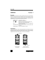
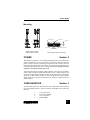
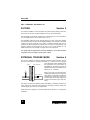
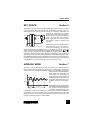
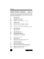
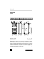
Series BG
DIGITAL FORCE GAUGES
User's Guide
User's Guide
TABLE OF CONTENTS
GENERAL - SECTION 1 .................................................................... 2
Controls ................................................................................ 2
Orientation ............................................................................ 2
Mounting ............................................................................... 3
POWER - SECTION 2 ........................................................................ 3
CONFIGURATION - SECTION 3 ......................................................... 3
FILTERS - SECTION 4 ....................................................................... 6
EXTERNAL TRIGGER MODE - SECTION 5 ....................................... 6
SET POINTS - SECTION 6 ................................................................. 7
AVERAGE MODE - SECTION 7 ......................................................... 7
GAUGE CONTROL LANGUAGE - SECTION 8 ................................... 8
OUTPUTS - SECTION 9 ................................................................... 10
RS-232 ................................................................................ 10
Mitutoyo BCD ...................................................................... 10
Analog ................................................................................. 10
I/O connector pin diagram ................................................... 10
CALIBRATION - SECTION 10 ........................................................... 11
SPECIFICATIONS - SECTION 11 ..................................................... 11
General ............................................................................... 11
Capacity x graduation .......................................................... 11
Dimensions ......................................................................... 12
WARRANTY - SECTION 12 ............................................................. 12
3
Series BG
GENERAL
Section 1
Controls
Six keys on the front panel are used for all functions and control of the instrument.
Some have more than one function, depending on the mode of operation. The main
functions are labeled above the keys and the secondary functions are below the keys
in smaller type. In the list below the secondary functions are in parenthesis. For a
detailed description of the secondary functions see Section 3.
POWER (ENTER)
UNITS (
)
ZERO (
)
Turns power on and off
Selects units of measurement
Zeroes any tare value (up to the full capacity of the
instrument) and clears the peak readings
DATA
Initiates a data transmission sequence (if equipped with
the communication option)
MODE (ADVANCE) Switches the display between normal and peak modes
of operation
CLEAR (ESCAPE) Clears peak readings from memory
Orientation
In order to accomodate a variety of testing requirements, the orientation of the loading
shaft may be set up in either of the two positions shown below. In order to change the
loading shaft orientation, simply unscrew two screws on the back side of the housing,
separate the two housing halves, rotate one half 180° and reassemble.
Loading shaft
SERIES
BG
SERIES
BG
POWER
UNITS
ZERO
POWER
UNITS
ZERO
DATA
MODE
CLEAR
DATA
MODE
CLEAR
ADVANCE
ESCAPE
ADVANCE
ESCAPE
Loading shaft
Upright orientation
(as supplied)
4
Alternate orientation
(for stand mounting, etc.)
User's Guide
Mounting
SERIES
BG
BOTTOM PLATE
DOWEL PIN
0.125 [3.2]
Ø 0.187 [4.75]
Gauge shown mounted
on Model TSC test stand
MOUNTING PLATE
Recommended use of a dowel pin
POWER
Section 2
The
gauge is powered by a 7.2-volt NiCd rechargeable battery. Since batteries are
subject to self-discharge, it may be necessary to recharge the unit after a prolonged
period of storage. Plug the accompanying charger into the AC outlet and insert the
charger plug into the receptacle on the gauge. The gauge may be operated for 8-10
hours after approximately 16-18 hours of charging. Do not use chargers other than
supplied or instrument damage may occur.
There are three levels of low battery voltage indication. At the first level, the display
shows a steady "LO BAT" indicating approximately one hour of charge remaining. The
second level is indicated by a flashing "LO BAT". At the third level, the whole display
except the "LO BAT" indicator will flash for three seconds after which time the gauge
will turn itself off. This prevents the instrument from working at voltages too low for
reliable operation.
CONFIGURATION
Section 3
The Series BG gauges have several features with programmable options allowing
many user-specified choices. In order to access the configuration menu, perform the
following:
1.
2.
3.
4.
Turn off the gauge
Press and hold MODE
Turn on the gauge
Release MODE
5
Series BG
The software version number will be displayed for a short time followed by "FLtA". The
following secondary functions of keys are used during the configuration process.
ADVANCE
ENTER
ESCAPE
Step through menu choices
Select a menu choice
Quit any function (no change)
Increment or decrement displayed values
&
The following list shows all configuration options. Italics indicate factory settings.
FLtA - Analog filter
FA 0
FA 1
2.5 Hz RC filter disabled
2.5 Hz RC filter enabled
FLTd - Digital filters
FC 1
FC 2
FC 4
FC 8
FP 1
FP 2
FP 4
FP 8
No filtering of current (displayed) readings
Average of 2 samples for each reading
Average of 4 samples for each reading
Average of 8 samples for each reading
No filtering of peak readings
Average of 2 samples for each peak reading
Average of 4 samples for each peak reading
Average of 8 samples for each peak reading
232 - RS-232 settings
232d
232E
Output Disabled
Output Enabled
300
600
1200
2400
4800
9600
300 baud
600 baud
1200 baud
2400 baud
4800 baud
9600 baud
7-1E
7-1o
7-2E
7-2o
7-2n
8-1E
8-1o
8-1n
8-2n
7
7
7
7
7
8
8
8
8
Ft F
Ft n
Full data (numeric + units)
Numeric data only
data bits, 1 stop bit, even parity
data bits, 1 stop bit, odd parity
data bits, 2 stop bits, even parity
data bits, 2 stop bits, odd parity
data bits, 2 stop bits, no parity
data bits, 1 stop bit, even parity
data bits, 1 stop bit, odd parity
data bits, 1 stop bit, no parity
data bits, 2 stop bits, no parity
out - Outputs selection (other than RS-232)
SP d
SP E
6
Set point outputs disabled
Set point outputs enabled
User's Guide
bcd d
bcd E
nPOL
POL
Mitutoyo BCD output disabled
Mitutoyo BCD output enabled
Mitutoyo readings without polarity (absolute value)
Mitutoyo readings with polarity; positive for compression, negative for tension
Et d
Et E
Et L
External trigger disabled
External trigger enabled in edge mode
External trigger enabled in level mode
EtHL
EtLH
Data capture during high to low transition of trigger signal
Data capture during low to high transition of trigger signal
Aout - Automatic output (RS-232)
no
1
2
4
8
16
32
64
128
Automatic output disabled
Every sample transmitted
Every 2nd sample transmitted
Every 4th sample transmitted
Every 8th sample transmitted
Every 16th sample transmitted
Every 32nd sample transmitted
Every 64th sample transmitted
Every 128th sample transmitted
AoFF - Automatic shutoff settings
no
1
5
10
20
30
Disabled
1-minute automatic shutoff
5-minute automatic shutoff
10-minute automatic shutoff
20-minute automatic shutoff
30-minute automatic shutoff
init - Initial (default) settings
LB
KG
N
Pounds as default units
Kilograms as default units
Newtons as default units
A
EtE/EtL
TC
PEAK T
PEAK C
Average mode at turn on
External trigger mode at turn on
Real time display at turn on
Peak tension display at turn on
Peak compression display at turn on
A - Average mode settings
AE
Ad
Average mode enabled
Average mode disabled
dEL
At
trF
Initial delay prompt
Average time prompt
Trigger force value prompt
7
Series BG
CAL - Calibration. See Section 10.
FILTERS
Section 4
For maximum flexibility in noise suppression and peak capturing ability of the instrument, there are two types of filters available to the user: analog and digital.
The analog filter is a simple RC network with a cutoff frequency of 2.5 Hz and attenuation of 20 dB/decade. It can be either turned on or off.
The digital filter utilizes the moving average technique in which consecutive readings
are "pushed" through a buffer and the displayed reading is the average of the buffer
contents. By varying the length of the buffer, a variable smoothing effect can be
achieved. The BG is equipped with a buffer which can hold up to eight readings. The
number of readings to be averaged can be set to 1,2,4 or 8. The selection of 1 will
disable the filter since the average of a single value is the value itself.
The analog and the digital filters should be disabled or set to their minimum
acceptable values for highest peak capture speed.
EXTERNAL TRIGGER MODE
Section 5
This mode of operation is useful for measuring electrical contact activation force as
well as synchronization of multiple instruments for a "snap-shot" view of applied
forces. When this mode is enabled through
USER - SUPPLIED
GAUGE
the configuration menu (see Section 3),
the MODE key will sequence through an
additional state which is indicated by the
flashing "C" or "T" indicator.
+5V
47K
SWITCH UNDER TEST
TRIG
3
GND
5
When in this mode, the instrument stops
updating the display when the trigger signal is applied. It is possible to capture the
reading with a normally open contact (high
to low transition of the trigger signal) or a
normally closed contact (low to high transition).
The display will show the captured reading until ZERO or CLEAR is pressed if the
"edge" mode is set. The "level" mode provides for the display to hold the reading only
until the trigger signal returns to its original state.
Please refer to the diagram for connection details and to Section 3 for configuration
information.
8
User's Guide
SET POINTS
Section 6
This feature is useful for tolerance checking (GO/NO GO) or alarm indication in process
control applications. Two limits, high and low, are specified and stored in the nonvolatile memory of the instrument and all readings are compared to these limits. The
results of the comparisons are indicated
40 ma MAX
through the three open-collector outputs proOUT
4
2N3904
vided on the 9-pin connector, thus providing
LOAD
SAME
8
"under", "in range" and "over" signaling.
AS ABOVE
9
These outputs can be connected to indica+
24V MAX
tors, buzzers or relays as required for the
_
application.
5
GND
After the Set Point mode is enabled through
the configuration menu (see Section 3),
pressing the MODE key will sequence
through an additional step indicated by "SP" on the display. To enter or change the
values of the set points press ENTER. The high set point is displayed. Use and
keys to increase or decrease the value and MODE for changing between tension and
compression. When the desired value is displayed, press ENTER and repeat the above
steps for the low set point. After entering both values "donE" will appear on the display.
Press ENTER to store the changes or ESCAPE to quit. In either case "SP" will appear on
the display and the ENTER key may be used for re-entering the set point change mode
or the MODE key for proceeding with the normal operation of the gauge.
USER - SUPPLIED
GAUGE
Section 7
AVERAGE MODE
This mode is used for obtaining an average force reading over a specified period of
time. Applications include measurement of peel force, muscle strength, frictional force
and any other tests requiring time-averaged readings. There are three user-programmable parameters associated with this
mode: trigger force, initial delay and
FORCE
average time. The programming of
these parameters and the enabling of
PEAK
the Average mode are done during the
AVG
AVE
gauge setup. Please refer to the "Configuration" section for more informaTRIGGER
FORCE
tion.
Press MODE until "A" is displayed and
then CLEAR or ZERO to begin testing.
The process of averaging begins as
soon as the programmed trigger force
is reached and is indicated by a flashing "A". The conclusion of the test is indicated by
an alternating "A" and the calculated value. The readings obtained during the initial
delay will not be part of the average, but the peak value is stored for later recall. A new
test may be started by pressing CLEAR or ZERO.
TIME
DELAY
AVERAGE TIME
9
Series BG
GAUGE CONTROL LANGUAGE
Section 8
The instrument can be controlled by an external device through the RS-232 channel.
The following is a list of supported commands and their interpretations. All commands
must be terminated with a Carriage Return character (hex 0D) or with a Carriage
Return/Line Feed combination (hex 0D+0A). The gauge responses are always terminated with a Carriage Return/Line Feed.
A
AD
AM
ATn
DELn
TRFn
Enable Average mode
Disable Average mode
Select Average mode (if enabled)
Average time. n=0.1-300.0 seconds
Initial delay. n=0.1-300.0 seconds
Trigger force. n=value (+ for compression, - for tension)
SP
SPD
SPHn
SPLn
Enable Set Point mode
Disable Set Point mode
High set point. n=value (+ for compression, - for tension)
Low set point. n=value (+ for compression, - for tension)
AOFFn
AOUTn
Auto-shutoff. n=0,1,5,10,20,30 minutes. 0=always on
Auto-transmit every nth reading. n=0,1,2,4,8,16,32,64,128. 0=disabled
LB
KG
N
G
Switch
Switch
Switch
Switch
ET
ETD
ETE
ETL
HL
LH
Enable External trigger mode
Disable External trigger mode
Edge triggered External trigger mode
Level triggered External trigger mode
Reading captured on a high to low transition
Reading captured on a low to high transition
CUR
PT
PC
CLR
Z
Current mode (real time display)
Peak Tension mode
Peak Compression mode
Clear peaks, start a new average, or external trigger test
Zero display and perform the CLR function
?
?C
?PT
?PC
?ET
?A
Request the displayed reading
Request the current reading
Request the peak tension reading
Request the peak compression reading
Request the reading obtained during the External trigger mode
Request the average reading obtained during the Average mode
FLTCn
FLTPn
FLTAn
Digital filter for current (displayed readings). n=1,2,4,8
Digital filter for peak readings. n=1,2,4,8
Analog filter (2.5 Hz). n=1,2. 1=on, 0=off
10
units to pounds
units to kilograms
units to Newtons
units grams
User's Guide
FULL
NUM
RS-232 transmission with units
RS-232 transmission without units (only numeric values)
MIT
MITD
POL
NPOL
PM
Enable Mitutoyo output
Disable Mitutoyo output
Mitutoyo outputs with polarity. (+ for compression, - for tension)
Mitutoyo outputs without polarity (absolute value)
Print/send data to a Mitutoyo compatible device
Sn
Cn
Rn
Set output bit (open collector, pull to ground). n=0,1,2
Clear output bit. n=0,1,2
Read current status of output bit or level of input pin. n=0,1,2,3
SAVE
CAL
LIST
Save current settings in nonvolatile memory
Enter Calibration mode. See Section 10 for more information
List current settings and status. Here is a typical LIST output:
V3.00;LB;PC;FLTC8;FLTP1;FLTA1;AOUT00;AOFF05;FULL;MIT;POL;B0
All fields are separated by ";". The first field shows the software version, the
last field shows the remaining battery power (B0=full charge, B3=minimum
power). All other fields show the status of settings and features using the
same abbreviations as the commands to set them.
Any detected errors are reported back by means of the following error codes.
*10
*11
*21
*22
*30
*31
*50
*51
Illegal command
Not applicable; e.g. SPHn command without enabling the set points
Invalid specifier; e.g. AOFF2
Value too large
Calibration weight too high
Calibration weight too low
Communication error
Command string too long
Following is a sample BASIC program illustrating the use of some commands. It switches
the units to kilograms and sets the display to zero. Press any key to get a reading on the
screen. Use "ESC" to exit the program.
10
20
30
40
50
60
70
80
90
100
CLS: OPEN "COM1:9600,N,8,1,RS,CS,DS,CD,LF" AS #1
PRINT #1 "KG"
PRINT #1 "Z"
PRINT "PRESS ANY KEY FOR READING OR <ESC> TO EXIT"
KEYPRS$=INKEY$: IF KEYPRS$="" THEN 50
IF KEYPRS$=CHR$(27) THEN SYSTEM
PRINT #1 "?"
LINE INPUT #1,A$
PRINT A$
GOTO 40
11
Series BG
OUTPUTS
Section 9
RS-232
The data transmission can be initiated by pressing the DATA key or by an external
device by sending ASCII "?" to the gauge. The gauge will respond by sending the
current reading in either full or numeric format, depending on the configuration settings
(see Section 3). Polarity sign indicates tensile (-) or compressive (+) forces. The
transmitted string has the following format:
[POLARITY (SPACE OR -)][DATA][SPACE][UNITS (IF ENABLED)][CRLF]
The display will flash "Err" and no data will be transmitted if DATA is pressed during the
average computation while in the Average mode or during the input scanning in the
External trigger mode.
Mitutoyo BCD
This output is useful for connection to data collectors, printers, multiplexers or any
other device capable of accepting Mitutoyo BCD data. The transmission is initiated by
the DATA key or by the receiving device (see Section 3 for settings).
Analog
This output can be used for chart recorders, oscilloscopes, data acquisition systems,
or any other compatible devices with analog inputs. The output produces ±1 volt at full
scale of the instrument. The polarity of the signal is positive for compression and
negative for tension.
I/O connector pin diagram
1
2
3
1
2
6
3
7
4
8
DB-9P
5
9
4
5
6
7
8
9
12
RS-232 receive
RS-232 transmit
Mitutoyo request
External trigger
Input bit 3
Mitutoyo clock
"Within" set point output
Output bit 2
Signal ground
+Analog signal
+12V DC
Mitutoyo ready
"Under" set point output
Output bit 1
Mitutoyo data
"Over" set point output
Output bit 0
Input
Output
Input
"
"
Output
"
"
--Output
Output
Output
"
"
Output
"
"
User's Guide
CALIBRATION
Section 10
Mount the gauge firmly with the loading shaft pointing downward. Go into the configuration mode as described in the previous section and select the calibration sub-menu
by pressing ENTER three times when the display shows 'CAL'. After the display shows
'null' press ZERO, while insuring that there is no weight on the loading shaft other than
the weight of the required attachments (hooks, etc.). The next displayed prompt is
'SPAn' at which time apply the exact weight equal to the full capacity of the gauge
in pounds and press ENTER. A successful calibration procedure is indicated by 'donE'
on the display. Press ENTER to save the new calibration data and to return to normal
operation. In some cases the display will show 'nnnn' or 'uuuu' to indicate excessive or
insufficient calibration weight. This can be caused by incorrect weights, tare weight of
over 10% of the full capacity of the gauge or an overloaded sensor. The calibration
procedure may be aborted without changing the previous calibration information at
any time by pressing ESCAPE.
SPECIFICATIONS
Section 11
General
Accuracy:
Tare capacity:
Overload capacity:
Sampling rate:
Display update:
Display:
Load cell deflection:
Outputs:
RS-232:
Mitutoyo:
Analog:
Connector:
Power:
Battery life:
Weight:
±0.2% of full scale ±1 count
110% of capacity. Display shows "----" at 110%
150% of capacity. Display shows "----" at 110%
65 samples per second
2.5-10 times per second in normal mode, depending on
filter settings. 65 times per second in peak mode
4-1/2-character LCD 0.3" [7.6 mm] high
Maximum 0.010" [0.25 mm] at full scale
Baud rates between 300 and 9600
Standard Mitutoyo SPC BCD output
±1 VDC ±0.25% FS
9-pin D-type male
7.2 NiCd battery or included AC adapter/charger
8-10 hours per charge
0.9 lbs [0.4 kg]
Capacity x graduation
BG012
BG025
BG05
BG2
BG5
BG10
BG20
BG50
BG100
BG200
BG500
0.12 x 0.00005 lbF
0.25 x 0.0001 lbF
0.5 x 0.0002 lbF
2 x 0.001 lbF
5 x 0.002 lbF
10 x 0.005 lbF
20 x 0.01 lbF
50 x 0.02 lbF
100 x 0.05 lbF
200 x 0.1 lbF
500 x 0.2 lbF
50 x 0.02 gF
100 x 0.05 gF
250 x 0.1 gF
1 x 0.0005 kgF
2 x 0.001 kgF
5 x 0.002 kgF
10 x 0.005 kgF
25 x 0.01 kgF
50 x 0.02 kgF
100 x 0.05 kgF
250 x 0.1 kgF
0.5 x 0.0002 N
1 x 0.0005 N
2 x 0.001 N
10 x 0.005 N
25 x 0.01 N
50 x 0.02 N
100 x 0.05 N
250 x 0.1 N
500 x 0.2 N
1000 x 0.5 N
2500 x 1 N
13
Series BG
Dimensions
in [mm]
MODEL
BG025-BG200
BG012-BG200
BG500
ØA
0.200 [5.8]
0.312 [7.9]
B
0.19 [4.8]
0.44 [11.2]
ØA
B
C
0.35 [8.9]
0.31 [7.9]
THREAD
#10-32
5/16-18
0.420 [10.7]
THREAD
C
SERIES
BG
0.88 [22.4]
2.250 [57.2]
5.90 [149.9]
POWER
DATA
UNITS
4.500 [114.3]
ZERO
MODE
CLEAR
ADVANCE
ESCAPE
Ø 0.188 [4.8]
#6-32 X4
2.53 [64.3]
WARRANTY
1.50 [38.1]
2.130 [54.0]
Section 12
Mark-10 Corporation expressly warrants to its buyer for three (3) years from the date
of delivery that the goods sold are free from defects in workmanship and materials.
Mark-10 Corporation will, at its option, repair or replace or refund the purchased price
of goods found to be defective. This remedy shall be the buyer's sole and exclusive
remedy. Any modification, abuse, exposure to corrosive environment or use other than
intended will void this warranty. This warranty is in lieu of all other warranties, including implied warranties of merchantability and fitness for an intended purpose. In no
event shall Mark-10 Corporation be liable for any incidental and consequential damages
in connection with goods sold or any part thereof.
14
User's Guide
15
.com
Mark-10 Corporation has been an innovator in the force and torque
measurement fields since 1979. We strive to achieve 100% customer satisfaction through excellence in product design, manufacturing and customer support. In addition to our standard line of products we can provide modifications and custom designs for OEM
applications. Our engineering team is eager to satisfy any special
requirements. Please contact us for further information or suggestions for improvement.
We Make A Measurable Difference In Force & Torque Measurement
Mark-10 Corporation
11 Dixon Avenue
Copiague, NY 11726 USA
1-888-MARK-TEN
Tel: 631-842-9200
Fax: 631-842-9201
Internet: www.mark-10.com
E-mail: [email protected]
REV 2 1004
32-1005