1
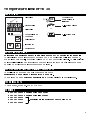
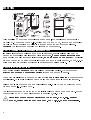
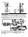
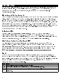
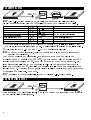
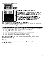
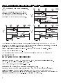
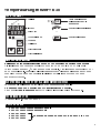
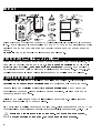
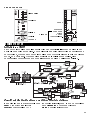
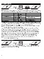
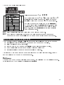
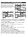
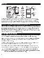
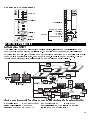
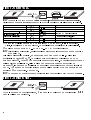
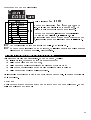
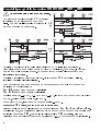
Temperature limiter TB 40 Temperaturbegrenzer TB 40 Limiteur de température TB 40 Operating instructions Bedienunganleitung Mode demploi 9499-040-24601 valid from/gültig ab/valable depuis: 8270 Page 1 ENGLISH DEUTSCH Seite 9 FRANCAIS Page 17 Front view ............................. 1 Frontansicht ......................... 9 Vue de la face avant ......... 17 Safety instructions .............. 1 Sicherheitshinweise ........... 9 Notices de sécurité .......... 17 Eelctromagnetic compat.... 1 Elektromag. Verträglichk. .. 9 Compatib. électromagn.... 17 Technical data ..................... 1 Technische Daten ............... 9 Caractéristiques techn. ... 17 Versions ................................ 1 Ausführungen ...................... 9 Versions .............................. 17 Mounting............................... 2 Montage.............................. 10 Montage ............................. 18 Earth terminal....................... 2 Erdanschluß ....................... 10 Borne de terre ................... 18 Electrical connections........ 2 Elektrischer Anschluß ...... 10 Raccordem. électrique .... 18 Operating structure............. 3 Bedienstruktur ................... 11 Structure dutilisation ....... 19 Operating level..................... 4 Bedien-Ebene .................... 12 Niveau «utilisation» .......... 20 Parameter level ................... 6 Parameter-Ebene .............. 14 Niveau «paramétrage» .... 22 Configuration level .............. 6 Konfigurations-Ebene....... 14 Niveau «configuration».... 22 Maintenance ........................ 7 Wartung .............................. 15 Entretien ............................. 23 Special versions .................. 8 Besondere Ausführung.... 16 Versions spéciales............ 24 à a Symbols used on the device EU conformity mark Attention, follow the operating instructions! à a Symbole auf dem Gerät EU-Konformitätskennzeichnung Achtung, Bedienungsanleitung beachten! à a Symbols à linstrument Estampille du conformité UE Attention, tenir comte du mode demploi. Tous droits sont réservés. Toute Alle Rechte vorbehalten. Ohne All rights reserved. No part of répresentation ou reproduction, vorhergehende schriftliche this documentation may be reproduced or published in any Genehmigung ist der Nachdruck, auch intégrale ou partielle, par quelque procédé que ce soit, faite sans le die auszugsweise fotomechanische form or by any means without consentement préalable par écrit oder anderweitige Wiedergabe, prior written permission from de lauteur, est interdite. dieses Dokumentes nicht gestattet. the copyright owner. A publication of Dies ist eine Dokumentation von Une publication de PMA Prozeß- und Maschinen-Automation GmbH P.O.Box 310 229 D-34058 Kassel Germany Temperature limiter TB 40 FRONT VIEW Alert alarm Actuate key or press as long as indicated Process value S.I.L. switch closed Limit value LED red (alarm 1) S.I.L. switch open LED green Selection key Increase key Decrease key SAFETY INSTRUCTION Following the enclosed safety instructions (9499 047 07101) is indispensable! The insulation of the instrument conforms to EN 61 010-1 with pollution degree 2, overvoltage category II, operating voltage 300 V and protection class I. Additional with horizontal installation: a protection to prevent live parts from dropping into the open housing of a withdrawn instrument must be fitted. ELECTROMAGNETIC COMPATIBILITY (89/336/EEC) The following European Generic Standards are met: Emission: EN 50081-1 and Immunity: EN 50082-2. The unit can be used without restrictions for residential and industrial areas. TECHNICAL DATA r Data sheet, order no. 9498 737 15333 VERSIONS 9404 9404 9404 9404 9404 407 407 407 407 407 46021 housing with dark front 46022 housing with light front 46031 46032 special versions without test to DIN 3440 46051 1 MOUNTING Ü With a sealing between controller front and panel, the panel reaches protection mode IP 54. For access to the S.I.L. switches REL1 and LOCK, remove the controller module from the housing by pulling it forwards at the top and bottom cut-outs. Caution! The instrument contains ESD-hazarded components. EARTH TERMINAL (for grounding interferences) If outside interference voltages act on the instrument, functional troubles may be caused (concerns also high-frequency interferences). For grounding interferences and ensuring the electromagnetic immunity, an earth must be connected: Terminal 6 must be connected to earth potential by means of a short cable (approx. 20 cm, e.g. to switch cabinet ground)! Keep this cable separate from mains cables. ELECTRICAL CONNECTIONS Keep mains cables separate from signal and measuring cables. We recommend twisted and screened measuring cables (screen connected to earth). Connected final elements must be equipped with protective circuits to manufacturer specification. This avoids voltage peaks which can cause trouble to the instrument. Relay 1 and logic output can be used simultaneously. Relay 1 can be switched off by means of the S.I.L. switch REL1. The instrument must be protected by an individual or common fuse for a max. power consumption of 10 VA per unit (standard fuse ratings, min. 1 A)! a 2 Signal and measurement circuits may carry max. 50 V r.m.s. against ground, mains circuits may carry max. 250 V r.m.s. between terminals. CONNECTING DIAGRAM Mains Alert alarm Reset Relay 1 Logic output Input Earth terminal Voltage Current Pt 100 Thermocouple OPERATING STRUCTURE Initialization (INIT) After supply voltage switch-on, the instrument is initialized and starts functioning at operating level. In order to prevent faulty function before settlement of input circuits, the functions are delayed by approx. 15 s after switch-on or re-configuration ( *). During this time, the relays are de-energized. This means an interruption of the energy supply and a alert alarm at relay 3. Access to the instrument levels and limit value adjustment 1=operating level 2=parameter level 3=configuration level E=end of access GW= limit value X=process value after TIMEOUT = modification effective LOCK= S.I.L. switch LOCK Con1= Configuration word 3 OPERATING LEVEL The process value is indicated in the upper display line, the limit value is indicated in the lower display line. Before initial adjustment, e.g. before commissioning, set the parameters and configure the instrument, if necessary ( configuration level). r parameter level, Behaviour of the instrument Task of the instrument is the interruption of the energy supply when reaching the limit value. Relay 1 switches the energy supply. De-energization is followed by locking. As long as the process value is below the limit value, relay 1 remains energized and the green LED is on. When the process value reaches or exceeds the limit value, relay 1 is de-energized and the energy supply is locked. Locking remains effective, also when the process value re-decreases below the limit value. Reset is only possible, when the sensor temperature has decreased below the limit value by the amount of the hysteresis (for reset r section Reset). Indicator LEDs Terature below the limit value (within limits). The red LED is on with relay 1 de-energized (limit value reached). The green LED extinguishes. When the proces value re-decreases below the limit value, the green LED will be lit additionally with the energy supply interrupted. The yellow LED provides limit value signalling. Alert alarm (relay 3 and yellow LED) LCL The alert alarm is adjustable relatively to the limit value in parameter and switches relay 3. Relay 3 is energized with the process value below the threshold + LCL (limit value - parameter LCL). When the process value reaches or exceeds the threshold, relay 3 is de-energized. This alert alarm is signalled via the yellow LED. The alert alarm must be used only for signalling and not for control purposes! Reset When the temperature re-decreases below the limit value (hysteresis 1 digit), the green LED lights up again and the red LED remains on. Resetting is only possible in this condition, either via the front panel keys (by pressing via an external contact parameter Loc 0 1 2 3 4 M and I simultaneously) or Ü across terminals 9 and 10. Selection is by means of Loc (r parameter level). Reset Ü Ü Reset only via the front panel keys (factory setting). Reset only by closing the external contact Reset only via the front panel keys and no process value display * Reset only by closing the external contact display . * across terminals 9 and 10. . across terminals 9 and 10 and no process value Ü The external contact is evaluated dynamically and a continuously closed contact (e.g. a switch) does not lead to resetting. Only a transition to closed position will cause resetting. The contact must be closed during at least 200 ms. * The process value display is swiched off, when neither an alert alarm was reached nor the energy supply was interrupted. Process value display is only with alert alarm and/or limit value reached. After resetting, the red LED is off and relay 1 is re-energized. With the green LED not lit when actuating the keys or activating the contact for resetting, the locking is not reset. In this case, relay 1 remains de-energized. Failure of the supply voltage will not lead to unlocking automatically. Behaviour with sensor break / measurement loop error For thermocouples, Pt 100 resistance thermometers and 4...20 mA inputs: FbF POL With sensor break, (or with Pt 100) is displayed and the instrument behaves as with process value higher than limit value: relay 1 is de-energized and the red LED is on. After removal of the error, the green LED is on again and reset is possible. For 0...20mA and 0...10V inputs: 0 is displayed with open input and sensor fail alarm is not possible. Behaviour with power supply failure Locking is stored in a non-volatile memory. In case of power supply failure after response of temperature limiting, relay 1 remains locked until reset after power recovery. + + Adjusting the limit value Only possible with S.I.L. switch LOCK=closed ( r Mounting). After pressing key M during min. 3 seconds, the upper display line changes from PASS. 0 is displayed in the lower line. Now, press keys I or D for adjusting the 2-digit pass number in the lower display line to 45 and confirme by M. If no key is pressed within 30 seconds, display PASS disappears and the process value to current process value will be displayed again. For adjusting the limit value, re-start from the beginning. PASS After correct entry of the pass number, will disappear from the upper display line. The current process value is displayed. The still unchanged effective limit value is displayed in the lower line. Now, the new limit value can be adjusted within its value range by means of M I or D. This adjustment can be confirmed with key or the new limit value will be effective after time-out (30 s). Subsequently, further adjustment is possible only after repetition of the above-mentioned procedure. If the pass number was not adjusted correctly, limit value adjustment remains locked. With S.I.L. switch LOCK open, limit value adjustment is locked. 5 PARAMETER LEVEL + With S.I.L. switch LOCK open, transition to parameter level is permitted. Display of parameters is with the symbol in the 1st and the value in the 2nd line. LCL Ü Loc r SPL 0 100 r SPH 0 100 dP * InL * InH * Ü When adjusting parameter LCL below 1 by pressing D, ---- is displayed and Parameter Symbol Value range Remark Alert alarm rel. 1 ... 9999 Reset 0 .. 3 meaning Lower adjustment limit x ... x measuring range dependent of input Upper adjustment limit x ... x type ( Decimal point (comma) 0 or 1 (0 = no decimal point) Lower sensor limit - 999 ... 9999 x0 span start Upper sensor limit - 999 ... 9999 x100 span end + reset configuration level) the alert alarm function is switched off. The alert alarm is relative to the limit value. * Only with input 0/4 ...20 mA and 0 ...10 V (r configuration level) Dependent of configuration, only the parameters relevant for the instrument function are displayed. Dependent of selected configuration, a parameter can be changed within the I or D. The adjustment will be effective after 2 s time-out or after pressing key M. Press key M for entry of the next parameter. The last parameter is followed by the operating level. Unless parameter adjustment is finished by pressing key M, transition to operating level is made automatically after a time-out of 30 s. Changing over to configuration level is possible from each parameter by pressing M during min. 5 seconds. permitted range by pressing keys + Transition to parameter level is locked by closing S.I.L. switch LOCK. CONFIGURATION LEVEL After transition to configuration level, the 2nd display line are indicated. 6 Con in the 1st and configuration word 0X00 in Structure of configuration code: 0 1 2 3 0 4 5 6 7 8 9 ++ Default value on delivery Input type L (0...900°C) Con1 type J (0...900°C) type K (0...1350°C) type N (0...1300°C) type S (0...1760°C) type R (0...1760°C) Pt 100 (-99...500°C) 0...20 mA lin. 4...20 mA lin. Con1= 0000 0 0 I D Configuration word can be changed within the permissible range by pressing keys and . The required adjustment is finished after pressing key . r M After changing, the instrument will be initialized ( Operation, Initialization). If the configuration was not changed before pressing key , transition to operating level without initialization is made. M 0...10 V lin. Exit from the configuration level is not via time-out. With input type re-configuration, parameters must be checked and matched to the new measuring range, if necessary. MAINTENANCE / BEHAVIOUR IN CASE OF TROUBLE The instrument needs no maintenance. The rules to be followed in case of trouble are: Check mains (voltage, frequency and correct connections), q q q q q check, if all connections are correct, check the correct function of the sensors and output elements, check the configuration word for required function and check the adjusted parameters for required operation. If the instrument still does not work properly after these checks, shut down the instrument and replace it. Cleaning Housing and front can be cleaned by means of a dry, lint-free cloth. No use of solvents or cleansing agents! 7 Special features of versions 9404 407 46031 / ... 46032 / ... 46051 a The test to DIN 3440 is omitted. LF With the additional parameter , the operation of both relays is determined. The drawings show the operations depending on the adjusted parameter. green red yellow green green red yellow red yellow When leaving the alarm or limiter range, relay 1 is locked. Reset (*) can be done as r described ( Reset ), however, the external contact is evaluated statically. A continuously closed contact will cause immediate reset. Relay 3 (alert alarm) will not be locked. With an operates at the limit value (GW). LCL setting of ---- , relay 3 The behaviour with sensor break / measurement loop error can be adjusted at configuration level: Con1 = 0xxx as process value > limit value Con1 = 1xxx as process value < limit value With input types 0...20 mA, 4...20 mA and 0...10 V, the response time is approx. 150 ms. With the other versions, it is 1 s. With Pt 100 input, the range is -99...600°C. FIL (filter, adjustable at parameter level) Effective only for process value display with Con1 = x7xx / x8xx / x9xx. For Parameter display, short-time process value variations can be reduced by adjustment of FIL parameter . Effect: the lower the adjusted value of, the higher the suppression of variations (adjustment range: 0.1...5.0 Hz; limiting frequency). 8 Temperaturbegrenzer TB 40 FRONTANSICHT Voralarm Taste betätigen oder so lange drücken wie angegeben Istwert Drahtschalter geschlossen Grenzwert LED rot (Alarm 1) Drahtschalter offen LED grün Wahltaste Wert vergrößern Wert verkleinern SICHERHEITSHINWEIS Beiliegende Sicherheitshinweise (9499 047 03601) sind unbedingt beachten! Die Isolierung des Gerätes entspricht der Norm EN 61 010-1 (VDE 0411-1) mit Verschmutzungsgrad 2, Überspannungskathegorie II, Arbeitsspannungsbereich 300 V und Schutzklasse I. Zusätzlich gilt bei waagerechtem Einbau: Bei gezogenem Gerät muß ein Schutz gegen das Hereinfallen leitender Teile in das offene Gehäuse angebracht werden. ELEKTROMAGNETISCHE VERTRÄGLICHKEIT (89/336/EWG) Es werden die folgenden Europäischen Fachgrundnormen erfüllt: Störaussendung: EN 50081-1 und Störfestigkeit: EN 50082-2. Das Gerät ist uneingeschränkt für Wohn- und Industriegebiete anwendbar. TECHNISCHE DATEN r Datenblatt Nr. 9498 737 15333 AUSFÜHRUNGEN 9404 9404 9404 9404 9404 407 407 407 407 407 46021 Gehäusefront dunkel 46021 Gehäusefront hell 46031 46032 Sonderausführungen ohne Prüfung nach DIN 3440 46051 9 MONTAGE Ü Mit der Dichtung zwischen Front und Schalttafel erhält die Tafelfront die Schutzart IP 54. Zum Zugriff auf die Drahtschalter REL1 und LOCK muß der Geräteeinschub mit kräftigem Zug an den Aussparungen des Frontrahmens aus dem Gehäuse gezogen werden. Achtung! Das Gerät enthält ESD-gefährdete Bauelemente. ERDANSCHLUSS (zum Ableiten von Störeinflüssen) Wenn von außen Störspannungen (auch hochfrequente) auf das Gerät einwirken, so kann dies zu Funktionsstörungen führen. Um Störungen abzuleiten und die Störfestigkeit sicherzustellen, muß eine Erde angeschlossen werden. Der Anschluß 6 muß mit einer kurzen Leitung mit Erdpotential verbunden werden (ca. 20 cm, z.B. an Schaltschrankmasse)! Diese Leitung ist getrennt von Netzleitungen zu verlegen. ELEKTRISCHER ANSCHLUSS Netzleitungen getrennt von Signal- und Meßleitungen verlegen. Wir empfehlen verdrillte und abgeschirmte Meßleitungen (Abschirmung mit Erde verbunden). Angeschlossene Schaltglieder sind mit Schutzbeschaltungen nach Angabe des Herstellers zu versehen. Dies vermeidet Spannungsspitzen, die eine Störung des Gerätes verursachen können. Relais 1 und Logikausgang können gleichzeitig benutzt werden. Relais 1 ist über internen Drahtschalter (REL 1) abschaltbar. Die Geräte sind zusätzlich entsprechend einer max. Leistungsaufnahme von 10 VA pro Gerät einzeln oder gemeinsam abzusichern (Standard-Sicherungswerte, min. 1 A)! a 10 Meß- und Signalstromkreise dürfen max. 50 Veff gegen Erde führen, Netzstromkreise dürfen max. 250 Veff gegeneinander führen. ANSCHLUSSPLAN Hilfsenergie Voralarm Reset Relais 1 LogikAusgang Eingang Meßerde Spannung Strom Pt 100 Thermoelem. BEDIENSTRUKTUR Initialisieren (INIT) Nach dem Einschalten der Hilfsenergie wird das Gerät initialisiert und beginnt in der Bedien-Ebene mit der Funktion. Um Fehlfunktionen beim Einschwingen der Eingänge zu vermeiden, werden nach dem Einschalten oder Umkonfigurieren ( *) die Funktionen um ca. 15 s verzögert. Während dieser Zeit sind die Relais abgeschaltet. Dies bedeutet eine Unterbrechung der Energiezufuhr und einen Voralarm an Relais 3. Zugriff auf die Geräteebenen und Grenzwerteinstellung 1=Bedien-Ebene 2=Parameter-Ebene 3=Konfigurations-Ebene E=Ende Durchlauf GW= Grenzwert X=Istwert nach Timeout = Änderung wirksam LOCK= Drahtschalter LOCK Con1= Konfigurationswort 11 BEDIEN-EBENE Die obere Anzeigezeile zeigt den Istwert, die untere Zeile zeigt den Grenzwert. Zur r erstmaligen Einstellung, z. B. vor der Inbetriebnahme, ist das Gerät zu parametrieren und evtl. zu konfigurieren ( Parameter-Ebene, Konfigurations-Ebene). Verhalten des Gerätes Aufgabe des Gerätes ist die Unterbrechung der Energiezufuhr bei Erreichen des Grenzwertes. Relais 1 schaltet die Energiezufuhr. Nach dem Ansprechen erfolgt eine Verriegelung. Solange der Istwert kleiner als der Grenzwert ist, bleibt Relais 1 angezogen und die grüne LED leuchtet. Erreicht oder überschreitet der Istwert den Grenzwert, so fällt Relais 1 ab und bleibt verriegelt, auch wenn der Istwert inzwischen wieder unter den Grenzwert fällt. Eine Rückstellung ist erst möglich, wenn die r Fühlertemperatur um den Betrag der Schaltdifferenz unter den Grenzwert gesunken ist (Rückstellung Abschnitt Rückstellung). LED-Anzeige Die grüne LED leuchtet, wenn die Temperatur kleiner als der Grenzwert ist (Gutbereich). Die rote LED leuchtet bei abgefallenem Relais 1 (Grenzwert erreicht), die grüne LED wird zunächst ausgeschaltet. Wenn der Istwert inzwischen wieder unter den Grenzwert fällt, leuchtet im verriegelten Zustand zusätzlich die grüne LED. Die gelbe LED zeigt einen Voralarm an. Voralarm (Relais 3 und gelbe LED) Der im Parameter + LCL relativ zum Grenzwert frei einstellbare Voralarmkontakt schaltet Relais 3. Relais 3 ist angezogen, wenn der Istwert kleiner als der Schaltpunkt LCL (Grenzwert, Wert des Parameters LCL) ist. Bei Gleichheit oder darüber fällt Relais 3 ab. Diesen Voralarm zeigt die gelbe LED an. Der Voralarm darf nur zur Signalisierung und nicht zur Regelung benutzt werden! Rückstellung Sinkt die Temperatur wieder unter den Grenzwert (Hysterese 1 Digit), so leuchtet die M grüne LED wieder auf, die rote LED bleibt weiterhin an. Nur in diesem Zustand kann I oder Ü eine Rückstellung erfolgen, entweder mit gleichzeitigem Drücken der Tasten Die Auswahl erfolgt im Parameter Loc 0 1 2 3 12 Loc (r Parameter-Ebene). beim Schließen eines externen Kontaktes und an den Anschlüssen 9 und 10. Reset Rückstellung nur über die Fronttasten (Auslieferzustand) Rückstellung nur über das Schließen des externen Kontaktes Ü Ü * Rückstellung nur über das Schließen des externen Kontaktes Ausblendung der Istwertanzeige . * (Anschlüsse 9 und 10) Rückstellung nur über die Fronttasten und Ausblendung der Istwertanzeige . (Anschlüsse 9 und 10) und Ü * Der externe Kontakt wird dynamisch ausgewertet, sodaß ein dauernd geschlossener Kontakt (z.B. ein Schalter) nicht zur Rückstellung führt. Nur der Übergang beim Schließen führt zur Rückstellung (min. 200 ms schließen). Die Istwertanzeige wird ausgeblendet, wenn weder ein Voralarm erreicht noch die Energierzufuhr unterbrochen ist. Der Istwert wird nur angezeigt, wenn der Voralarm und/oder der Grenzwert erreicht ist. Nach der Rückstellung verlischt die rote LED und das Relais 1 wieder an. Leuchtet die grüne LED nicht und es wird eine Rückstellung versucht (Tasten oder externer Kontakt), so erfolgt keine Rückstellung der Verriegelung und Relais 1 bleibt abgefallen. Ein Ausfall der Hilfsenergie führt nicht zur selbsttätigen Entriegelung. Verhalten bei Fühlerbruch / Meßkreisfehler Für Thermoelemente, Widerstandsthermometer (Pt100) und 4...20mA-Eingänge: Bei Fühlerbruch steht FbF (oder POL bei Pt 100) in der Anzeige, und das Gerät verhält sich wie bei Istwert größer Grenzwert: Relais 1 fällt ab und die rote LED leuchtet. Nach Beheben des Meßkreisfehlers leuchtet die grüne LED wieder auf, und die Rückstellung ist möglich. Für 0...20mA und 0...10V-Eingänge: 0 wird angezeigt (Eingang offen) und die Meldung Fühlerfehler ist nicht möglich. Verhalten bei Netzausfall Der Verriegelungsfall wird netzausfallsicher gespeichert. Wenn nach Ansprechen des Gerätes ein Spannungsausfall erfolgt und die Spannung wiederkehrt, so bleibt die + + Verriegelung des Relais 1 bis zur Rückstellung bestehen. Einstellung des Grenzwertes Nur möglich, wenn Drahtschalter LOCK= geschlossen (r Montage). M PASS. Die untere Anzeige zeigt 0. Nun kann mit I oder D die 2-stellige Passzahl in der unteren Anzeige auf 45 eingestellt und mit M bestätigt Nach längerem Drücken (min. 3 Sekunden) der Taste wechselt die obere Anzeige vom Istwert zu werden. Wird innerhalb 30 Sekunden keine Taste betätigt, verlischt die Anzeige PASS und es wird der aktuelle Istwert angezeigt. Zur Einstellung des Grenzwertes muß von vorn begonnen werden. Nach korrekter Passzahl-Eingabe verlischt in der oberen Anzeigezeile PASS. Der aktuelle Istwert wird angezeigt. In der unteren Zeile wird der noch unveränderte wirksame Grenzwert angezeigt. Nun kann mit I oder D M der neue Grenzwert innerhalb seines Wertebereiches einge- stellt werden. Die Einstellung kann mit bestätigt werden oder der neue Grenzwert wird nach Timeout (30s) wirksam. Danach ist eine weitere Verstellung erst nach Wiederholung der oben genannten Prozedur möglich. Wurde die Passzahl nicht korrekt eingestellt, bleibt die Verstellung des Grenzwertes verriegelt. Die Verstellung des Grenzwertes ist bei geöffnetem Drahtschalter LOCK blockiert. 13 PARAMETER-EBENE + Bei offnem Drahtschalter LOCK ist der Übergang in die Parameterebene möglich. Das Parameter-Symbol wird in der 1. Zeile und der Wert in der 2. Zeile angezeigt. Parameter LCL Ü Loc r SPL 0 100 r SPH 0 100 dP * InL * InH * LCL mit D kleiner 1, so zeigt die Anzeige ---- und die Symbol Voralarm Wertebereich Bemerkung rel. 1 ... 9999 Rückstellung Untere Einstellgrenze GW Obere Einstellgrenze GW Dezimalpunkt (Komma) 0 .. 3 Bedeutung x ... x Meßbereich entsprechend Eingangsart x ... x ( 0 oder 1 untere Sensorgrenze obere Sensorgrenze Rückstellung Konfiguration-Ebene) (0 = kein Dezimalpunkt ) - 999 ... 9999 x0 Meßbereichsanfang - 999 ... 9999 x100 Meßbereichsende Ü Stellt man den Parameter Funktion Voralarm ist ausgeschaltet. Der Voralarmkontakt ist relativ zum Grenzwert. * Nur bei Eingang 0/4 ...20 mA und 0 ...10 V (r Konfiguration-Ebene) + In Abhängigkeit von der Konfiguration werden nur die für die jeweilige Gerätefunktion relevanten Parameter angezeigt. I D Je nach gewählter Konfiguration kann ein Parameter mit den Tasten oder im zugelassenen Bereich veränder werden. Die Einstellung wird nach 2 s Timeout oder M M nach Drücken von wirksam. Mit gelangt man zum nächsten Parameter. Nach dem letzten Parameter gelangt man zur Bedienebene. Wird die Parametereinstellung M nicht mit der Taste beendet, so wird nach einer Timeout von 30 s automatisch in die Bedien-Ebene übergegangen. Von jedem Parameter aus ermöglicht längeres + (min. 5 Sekunden) Drücken von M einen Wechsel in die Konfigurations-Ebene. Der Übergang in die Parameterebene wird über den geschlossenen Drahtschalter LOCK gesperrt. KONFIGURATIONS-EBENE Nach Übergang in die Konfigurationsebene zeigt die 1. Anzeigenzeile 2. Zeile das Konfigurationswort 14 0X00. Con1 und die Aufbau des Konfigurations-Codes: 0 1 2 3 0 4 5 6 7 8 9 ++ Auslieferungszustand Eingang Typ L (0...900°C) Con1 Typ J (0...900°C) Typ K (0...1350°C) Typ N 0...1300°C) Typ S (0...1760°C) Typ R (0...1760°C) Pt 100 (-99...500°C) 0...20 mA lin. 4...20 mA lin. 0...10 V lin. Con1= 0000 0 0 I Das Konfigurationswort läßt sich mit und im zulässigen Bereich verändern. Die gewünschte Einstellung wird nach Drücken von gespeichert. r M D Nach einer Veränderung wird das Gerät initialisiert ( Abschnitt Bedienung, Initialisierung). Wurde die Konfiguration vor dem Drücken der Taste nicht verändert, wird ohne Initialisierung in die BedienEbene übergegangen. M Die Konfigurations-Ebene wird nicht über Timeout beendet. Nach einer Konfigurationsänderung der Eingangsart müssen Parameter überprüft und gegebenenfalls an den neuen Meßbereich angepaßt werden. WARTUNG / VERHALTEN BEI STÖRUNG Das Gerät ist wartungsfrei. Im Falle einer Störung sind folgende Punkte zu prüfen: die Hilfsenergie auf Spannung, Frequenz und korrekten Anschluß, q q q q q alle Anschlüsse auf Korrektheit, die Sensoren und Ausgangsschaltglieder auf einwandfreie Funktion, das Konfigurationswort auf benötigte Wirkungsweise und die eingestellten Parameter auf erforderliche Wirkung. Arbeitet das Gerät nach diesen Prüfungen immer noch nicht einwandfrei, so ist es außer Betrieb zu nehmen und auszutauschen. Reinigung Gehäuse und Front können mit einem trockenen, fusselfreien Tuch gereinigt werden. Kein Einsatz von Lösungs- oder Reinigungsmitteln! 15 Besonderheiten der Ausführungen 9404 407 46031 / ... 46032 / ... 46051 a Die Prüfung nach DIN 3440 entfällt. LF Mit dem zusätzlichen Parameter wird die Arbeitsweise der beiden Relais festgelegt. Die Zeichnungen zeigen die Wirkungsweise in Abhängigkeit des Parameters. grün rot gelb grün grün rot gelb rot gelb Das Relais 1 wird beim Verlassen des Alarm- bzw. Begrenzerbereichs verriegelt. Die r Rückstellung (*) kann wie beschrieben durchgeführt werden ( Rückstellung), der externe Kontakt wird jedoch statisch ausgewertet. Ein ständig geschlossener Kontakt führt zu sofortiger Rückstellung. Das Relais 3 (Voralarm) wird nicht verriegelt. Ist der arbeitet das Relais 3 am Grenzwert (GW). LCL auf ---- eingestellt, so Das Verhalten bei Fühlerbruch/ Meßkreisfehler ist in der Konfigurations-Ebene einstellbar: bei bei Con1 = 0xxx wie Istwert > Grenzwert Con1 = 1xxx wie Istwert < Grenzwert Bei den Eingangsarten 0...20 mA, 4...20 mA und 0...10 V beträgt die Ansprechzeit ca. 150 ms, bei den anderen Geräten ist sie 1 s. Bei der Eingangsart Pt 100 ist der Meßbereich -99...600°C. FIL (Filter, in der Parameter-Ebene einstellbar) Wirkt nur für die Istwertanzeige bei Con1 = x7xx / x8xx / x9xx. Für die Anzeige Parameter können kurzzeitige Schwankungen des Istwertes durch Einstellung des Parameters FIL reduziert werden. Wirkung: Je kleiner der eingestellte Wert ist, umso stärker werden Schwankungen unterdrückt (Einstellbereich: 0,1...5,0 Hz; Grenzfrequenz). 16 Limiteur de température TB 40 VUE DE LA FACE AVANT Préalarme Taper la touche ou lenfoncer tant que spécifié Valeur de la mesure Contact à crochet fermé Valeur limite LED rouge (alarme 1) Contact à crochet ouvert LED verte Touche de sélection Augmenter la valeur Diminuer la valeur NOTICES DE SECURITE Tenir compte des notices de sécurité (9499 047 03601) ci-jointes! Le isolement de lappareil conforme à la norme EN 61 010-1 avec degrée de pollution 2, catégorie de surtension II, gamme de tension service 300 V et classe de protection I. Additionelen position horizontale: lorsque lappareil est retiré, prévoir un dispositif pour empêcher des pièces sous tension de tomber dans le boîtier ouvert. COMPATIBILITE ELECTROMAGNETIQUE (89/336/CEE) Lappareil, répond aux normes génériques européennes suivantes: EN 50081-1 «Emission de parasites» et EN 50082-2 «Résistance au brouillage». Lappareil peut être utilisé sans réserve dans des zones industrielles et dhabitation. CARACTERISTIQUES TECHNIQUES r fiche technique no. 9498 737 15333 VERSIONS 9404 9404 9404 9404 9404 407 407 407 407 407 46021 46022 46031 46032 46051 Boîtier/face avant foncé Boîtier/face avant clair Versions spéciales sans contrôle selon DIN 3440 17 MONTAGE Ü Un joint détanchéité entre la face avant et le panneau permet au panneau une protection selon IP 54. Pour accéder aux contacts à crochet REL1 et LOCK, saisir le module par les découpes sup. et inf. et lenlever du boîtier en le tirant vers lavant. Attention! Lappareil contient des pièces sensibles à la décharge électrostatique. BORNE DE TERRE (pour la mise à la terre des interférences) Si lappareil est sous linfluence dinterférences ext., lappareil risque dêtre mis en panne (ceci concerne également les interférences à haute fréquence). Afin de mettre les interférences à la terre et de garantir la résistance au brouillage, une borne de mis à la terre doit être connectée: Relier la borne 6 au potentiel de terre au moyen dun câble court (environ 20 cm, p.ex. à la terre de larmoire de commande)! Ce câble doit être maintenu séparé des câbles secteur. RACCORDEMENTS ELECTRIQUES Maintenir les câbles secteur séparés des câbles signal et mesure. Nous recommandons des câbles de mesure torsadées et blindées (blindage relier à la terre). Si lon connecte des organes de commutation, il faut prévoir des cicuits de protection selon la spécification du fabricant, pour éviter des pics de tension qui risquent de mettre lappareil en panne. Le relais 1 et la sortie logique peuvent être utilisés simultanément. Le relais 1 peut être supprimé par lintermédiaire dun contact à crochet (REL 1). Protéger les unités par un fusible supplémentaire individuel ou commun pour une consommation de puissance max. de 10 VA par unité (calibres standard, min. 1 A)! a 18 Le potentiel max. admissible par rapport à la terre dans les circuits de mesure et du signal est de 50 Veff. Le potentiel max. admissible entre les bornes des circuits du secteur est de 250 Veff. SCHEMA DE RACCORDEMENT Secteur Préalarm Annulation Relais 1 Sortie logique Entrée Borne de terre Tension Courant Pt 100 Thermocouple STRUCTURE DUTILISATION Initialisation (INIT) Après lenclenchement de la tension dalimentation, linstrument est initialisé et se met à fonctionner au niveau «utilisation». Pour éviter des défauts avant léquilibrage des circuits de sortie, les fonctions sont temporisées denviron 15 s après lenclenchement ou la reconfiguration (*). Pendant ce temps, les relais sont désexcités. Cela se traduit par une interruption de lénergie et une préalarme sur le relais 3. Accès au niveaux de fonctionnement avec réglage de la valeur limite: 1=«utilisation» 2=«paramétrage» 3=«configuration» E=fin accès GW= valeur limite X=mesure après time-out = modification effective LOCK= contact à crochet LOCK Con1= mot de configuration 19 NIVEAU «UTILISATION» La valeur de la mesure est indiquée dans la ligne supérieure de laffichage, la valeur limite est indiquée dans la ligne inférieure. Avant le réglage initial, p.ex. avant la mise r en service, régler les paramètres et configurer lappareil, si nécessaire ( «paramétrage», «configuration»). Comportement de linstrument La tâche de linstrument consiste à couper lénergie lorsque la valeur limite est atteinte. Lalimentation dénergie est commutée par le relais 1. Lorsque celui-ci tombe au repos, lalimentation dénergie est interdite. Tant que la mesure est inférieure à la valeur limite, le relais 1 reste excité et la LED verte est allumée. Lorsque la mesure atteint ou dépasse la valeur limite, le relais 1 est désexcité et lalimentation dénergie est interdite. Linterdiction reste effective également lorsque la mesure rediminue sous la valeur limite. Lannulation de linterdiction est possible seulement, lorsque la r température du capteur a diminué sous la valeur limite du montant de lhystérésis (pour lannulation paragraphe Annulation). Témoins LED La LED verte est allumée lorsque la température est inférieure à la valeur limite (à lint. des limites). La LED rouge est allumée lorsque le relais 1 est désexcité (valeur limite atteinte). La LED verte séteind. Lorsque la mesure rediminue sous la valeur limite, la LED verte est également allumée à létat dinterdiction. La LED jaune indique une préalarme. Préalarme (relais 3 et LED jaune) La préalarme est réglable par rapport à la valeur limite dans le paramètre + LCL. Elle commute le relais 3. Le relais 3 est excité lorsque la mesure est inférieure au seuil LCL (valeur limite - paramètre LCL). Lorsque la mesure atteint ou dépasse le seuil, le relais 3 est désexcité. Cette préalarme est signalée par lintermédiaire de la LED jaune. Utiliser la préalarme seulement pour la signalisation et non pas pour la régulation! Annulation Lorsque la température est de nouveau inférieure à la valeur limite (hystérésis 1 digit), M la LED verte se rallume et la LED rouge reste allumée. Lannulation est possible seule- I ou en fermant un contact externe Ü sur les bornes 9 et 10. Ce choix seffectue à laide du paramètre Loc (r «paramétrage»). Loc 0 1 Ü 2 * ment dans cet état, par lintermédiaire des touches dans la face avant (en tapant simultanément) Annulation Annulation seulement par lint. des touches dans la face avant (réglé à lusine) Annulation seulement en fermant le contact externe aux bornes 9 et 10 . Annulation seulement par lint. des touches dans la face avant. La mesure nest pas affichée 3 20 . * Annulation seulement en fermant le contact externe La mesure nest pas affichée . Ü aux bornes 9 et 10 et Ü Le contact externe est évalué dynamiquement et un contact fermé continuellemt (p.ex. un commutateur) ne conduit pas à lannulation. Lannulation est réalisée seulement par le * passage dans la position fermée. Le contact doit être fermé pendant min. 200 ms. La mesure nest pas affichée, lorsque ni une préalarme a été atteinte ni lalimentation dénergie a été coupée. La mesure est affiché seulement lorsque la préalarme et/ou la valeur limite ont été atteintes. Après lannulation, la LED rouge est éteinte, et le relais 1 est de nouveau excité. Si la LED verte nest pas allumée lorsquon tape les touches ou active le contact pour lannulation, linterdiction nest pas annulée. Dan un tel cas, le relais 1 reste désexcité. Une défaillance de lalimentation ne provoque pas automatiquement le déblocage. Comportement en cas de rupture du capteur / erreur de mesure Pour les entrées par thermocouple, sonde à résistance (Pt 100) et 4...20 mA: En cas de rupture du capteur, FbF est affiché (et POL avec Pt 100) linstrument comporte comme en cas de mesure inférieure à la valeur limite. Le relais 1 est désexcité et la LED rouge est allumée. Après lenlèvement de lerreur, la LED verte sest rallumée et lannulation est possible. Pour les entrées 0...20mA et 0...10V: 0 est affiché (entrée ouverte) et lalarme capteur nest pas possible. Comportement en cas de défaillance de lalimentation Linterdiction est mise dans une mémoire non volatile. Dans le cas dune défaillance de lalimentation après la réponse de la limitation de température, le relais 1 reste + + interdit jusquà lactivation de lannulation après le retour de lalimentation. Réglage de la valeur limite change de la mesure à pendant min. 3 secondes, la ligne daffichage supérieure 45 et confirmé à laide de la touche M. ou à LOCK=fermé (r Montage). PASS. 0 est affiché dans la ligne inférieure. Taper ensuite I Après appui sur la touche D M Possible seulement lorsque le contact à crochet pour régler le numéro de passe à 2 chiffres dans la ligne inférieure de laffichage Si aucune touche nest tapée pendant 30 secondes, laffichage PASS disparaît. La mesure actuelle est affichée de nouveau. Pour le réglage de la valeur limite, répéter la procédure. Après lentrée correcte du numéro de passe, PASS disparaît de la ligne supérieure de laffichage. La mesure actuelle est affichée. Dans la ligne inférieure, la valeur limite effective encore inchangée est affichée. I D M La valeur limite nouvelle peut alors être réglée à lint. de sa plage de réglage en tapant ou . Ce réglage peut être confirmé en pressant ou la valeur limite nouvelle sera effective après «time-out» (30 s). Ensuite, le réglage peut être poursuivi seulement après la répétition de la procédure mentionnée ci-avant. Si le numéro de passe na pas été réglé correctement, le réglage de la valeur limite reste interdit. Lorsque le contact à crochet LOCK est ouvert, le réglage de la valeur limite est bloqué. 21 NIVEAU «PARAMETRAGE» + Lorsque le contact à crochet LOCK est ouvert, le passage en «paramétrage» est autorisé. Laffichage des paramètres seffectue avec le symbole dans la 1° et la valeur dans la 2° ligne. LCL Ü Loc r SPL 0 100 r SPH 0 100 dP * InL * InH * Ü Lorsquon règle le paramètre LCL inférieur à 1 en tapant D, ---- est affiché. Paramètre Symbole Plage Remarque Préalarme rel. 1 ... 9999 Annulation 0 .. 3 Signification Limite de réglage inf. x ... x gamme de mesure selon le type Limite de réglage sup. x ... x dentrée ( Annulation «configuration») Point décimal (virgule) 0 ou 1 (0 = sans point décimal) Limite inférieure capteur - 999 ... 9999 x0 début de gamme Limite supérieure capteur - 999 ... 9999 x100 fin de gamme + * r Ainsi, la préalarme à été supprimée. La préalalarme est relative à la valeur limite. Seulement pour entrée 0/4 ...20 mA et 0...10 V ( «configuration») Suivant la configuration, seulement les paramètres importants pour une fonction sont affichés. I D M M Selon la configuration choisie, un paramètre peut être changé à lint. de la plage admissible en tapant après appui sur M M ou . Taper . Le réglage sera effectif après «time-out» de 2 s ou pour entrer le paramètre suivant. Le dernier paramètre est suivi du niveau «utilisation». Si le réglage des paramètres nest pas terminé en + pressant , le passage en «utilisation» est réalisé automatiquement après «time-out» de 30 s. Le passage en «configuration» est possible à partir de chaque paramètre par appui sur pendant min. 5 secondes. Le passage en «paramétrage» est interdit en fermant le contact à crochet LOCK. NIVEAU «CONFIGURATION» Après le passage en «configuration», dans la 2° ligne sont affichés. 22 Con dans la 1° et le mot de configuration 0X00 Structure du code de configuration: 0 1 2 3 0 4 5 6 7 8 9 ++ Réglé à lusine: Entrée Con1= 0000 type L (0...900°C) Con1 type J (0...900°C) type K (0...1350°C) type N (0...1300°C) type S (0...1760°C) type R (0...1760°C) Pt 100 (-99..500°C) 0...20 mA lin. 4...20 mA lin. 0...10 V lin. 0 0 I D M Le mot de configuration peut être changé à lint. de la plage admissible en tapant et . Le réglage requis est terminé après appui sur . r M Après un changement, linstrument sera initialisé ( paragraphe Utilisation, Initialisation). Si la configuration na pas été changée avant dappuyer sur , lappareil passe en «utilisation» sans initialisation. La «configuration» nest pas terminée par lint. de «time-out». En cas de reconfiguration du type dentrée, vérifier les paramètres et les adapter à la gamme de mesure nouvelle, si nécessaire. ENTRETIEN / COMPORTEMENT EN CAS DE PANNE Linstrument nexige pas dentretien. En cas de panne, vérifier: lalimentation, fréquence et raccordement corrects? q q q q q si les connexions sont en bon état, si les capteurs et éléments finaux fonctionnent correctement si le mot de configuration est approprié pour la fonction requise et si les paramètres réglés ont leffet désiré. Si lappareil ne fonctionne toujours pas correctement après cela, le mettre hors circuit et le remplacer. Nettoyage Boîtier et face avant peut être nettoyé par un torchon sèche et non pelucheux. Ne pas utilise du solvant ou détergent! 23 Caractéristiques spéciales des versions 9404 407 46031 / ... 46032 / ... 46051 a Le contrôle selon DIN 3440 est omis. LF Le paramètre supplémentaire détermine le principe de fonctionnement des deux relais. Les croquis illustrent le fonctionnement en fonction du paramètre. verte rouge jaune verte verte rouge rouge jaune jaune Le relais 1 est bloqué lorsque la plage dalarme ou de limitation est quittée. r Lannulation (*) peut se faire comme décrit ( Annulation), cependant, le contact externe est évalué statiquement. Un contact fermé continuellement provoque lannulation immédiate. Le relais 3 (préalarme) nest pas bloqué. Si le contact le relais 3 travaille à la valeur limite. LCL est réglé à ----, Le comportement en cas de rupture du capteur/erreur de boucle de mesure est réglable en «configuration»: Con1 = 0xxx comme mesur Con1 = 1xxx comme m e > valeur limite esure < valeur limite Pour les entrées 0...20 mA, 4...20 mA and 0...10 V, le temps de réponse est denviron 150 ms. Sur les autres versions, il est 1 s. Pour entrée Pt 100, la gamme de mesure est -99...600°C. Paramètre FIL (filtre, réglable au «paramétrage») Con1 7 8 9 Efficace seulement pour laffichage de mesure lorsque = x xx / x xx / x xx. Pour laffichage, des variations de la mesure de courte durée peuvent être réduites en FIL FIL réglant le paramètre . Effet: plus la valeur réglée est faible, plus des variations sont supprimées (gamme de réglage: 01,...5,0 Hz; fréquence de limitation). 24 25 Subject to alterations without notice. © PMA Prozeß- und Maschinen-Automation GmbH Bei Änderungen erfolgt keine Mitteilung. P.O.B. 310 229, D-34058 Kassel, Germany Modifications sans avertissement réservées. Printed in Germany 9499-040-24601 (9811) A6