1
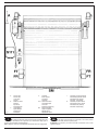
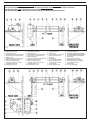
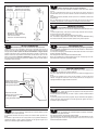
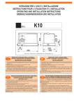
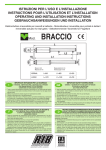
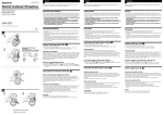
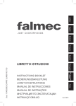
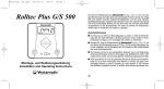
ISTRUZIONI PER L'USO E L’INSTALLAZIONE
INSTRUCTIONS POUR L'UTILISATION ET L’INSTALLATION
OPERATING AND INSTALLATION INSTRUCTIONS
GEBRAUCHSANWEISUNGEN UND INSTALLATION
JOLLY SIDE
Elettroriduttore per Serrande Industriali non bilanciate - Moto-réducteur pour Grilles Industrielles
Actuator for Industrial Shutters - Elektrogetriebemotor für die Automation von Industriesträger
Mod.
Misure in mm
Mesures en mm
Measurements in mm
Abmessungen in mm
IMPORTANTI ISTRUZIONI PER LA SICUREZZA
ATTENZIONE - É IMPORTANTE PER LA SICUREZZA DELLE PERSONE
CHE VENGANO SEGUITE TUTTE LE ISTRUZIONI
CONSERVARE CON CURA QUESTE ISTRUZIONI
1° - Tenete i comandi dell'automatismo (pulsantiera, telecomando etc.) fuori dalla portata dei bambini.
I comandi devono essere posti ad un’altezza minima di 1,5mt dal suolo e fuori dal raggio d’azione
delle parti mobili.
2° - Effettuare le operazioni di comando da punti ove l'automazione sia visibile.
3° - Utilizzare i telecomandi solo in vista dell'automazione.
4° - Avvertenze: Sulle altre misure di Protezione contro rischi attinenti l'installazione o l'utilizzazione
del Prodotto vedi, a completamento di questo libretto di Istruzioni, le Avvertenze RIB allegate.
Qualora queste non siano pervenute chiederne l'immediato invio all'Ufficio Commerciale RIB.
LA DITTA RIB NON ACCETTA NESSUNA RESPONSABILITÀ per eventuali danni provocati dalla
mancata osservanza nell'installazione delle norme di sicurezza e le leggi attualmente in vigore.
I
INSTRUCTIONS IMPORTANTES POUR LA SECURITE
IL EST IMPORTANT POUR LA SECURITE DES PERSONNES
DE SUIVRE ATTENTIVEMENT TOUTES INSTRUCTIONS
GARDER MODE D’EMPLOI
1° - Gardez les commandes de l'automatisme (boutons poussoirs, telecommande etc.) hors de la
portée des enfants. Les commandes doivent être placées au minimum à 1,5 m du sol, et hors de
rayon d’action des pièces mobiles.
2° - Il faut donner les commandes d'un lieu, où on peut voir l'automatisme.
3° - Il faut utiliser les émetteurs seulement si on voit le portail.
4° - Avertissements: Sur les autres mesures de Protection contre les risques relatifs a l'installation ou
l'utilisation du Produit, voir, à titre de complément de ce livret d'instructions, les Avertissements
RIB ci-jointes. Dans le cas où celles-ci ne vous seraient pas parvenues, en demander l'envoi
immédiat au Bureau Commercial Etranger RIB (Ufficio Commerciale Estero RIB).
L'ENTREPRISE R.I.B. N'ACCEPTE AUCUNE RESPONSABILITÉ pour des dommages éventuels
provoqués par le manque d'observation lors de l'installation des normes de sécurité et lois
actuellement en vigueur.
F
IMPORTANT SAFETY INSTRUCTIONS
WARNING - IT IS IMPORTANT FOR THE SAFETY OF PERSONS
TO FOLLOW ALL INSTRUCTIONS
SAVE THESE INSTRUCTIONS
1° - Keep the automatism control (push-button, remote control, etc) out of the reach of children. The
control systems must be installed at a minimum hight of 1.5 mt from the groundsurface and not
interfere with the mobile parts.
2° - Command pulses must be given from sites, where You can see the gate.
3° - Use transmitters only if You can see the gate.
4° - Warnings: when you have finished reading this instruction booklet, please refer to the RIB
instructions attached for the other precautionary measures against risks connected with the
installation or use of the product. If you have not received these, ask RIB Export Office to send
them immediately.
R.I.B. ACCEPTS IS NOT LIABLE for any damage caused by the not abiding ofthe safety regulations
and laws at present in force not being observed during installation.
GB
WICHTIGE GEBRAUCHSANWEISUNGEN FÜR DIE SICHERHEIT
ACHTUNG - UM PERSONEN VOLLKOMMEND GARANTIEREN ZU KöNNEN IST ES
WICHTIG DASS ALLE INSTALLLATIONSVORSCHRIFTEN BEOBACHTET WERDEN
1° - Bewahren Sie die Geräte für die automatische Steuerung (Drucktaster,
Funksender, u.s.w.) an einem für Kinder unzugänglichen Platz auf. Die Steuerungen müssen
mindestens auf einer minimal Höhe von 1,5 mt gestellt werden und sich ausserhalb der Raum der
bewegenden Teile befinden.
2° - Die Betätigung der automatischen Steuerungs soll nur ausgeführt werden wenn die automatische
Anlage sichtbar ist.
3° - Die Funksender nur inn den Fällen benützen wenn die automatische Anlage sichtbar ist.
4° - Achtung: Für weitere Schutzmaßnahmen im Rahmen der Installation und Anwendung der
Produkte siehe die beiliegenden RlB-Sicherheitshinweise, die diese Gebrauchsanleitung
ergänzen. Sollten Sie diese nicht erhalten haben, fördern Sie sie bitte sofort bei der RlB
Exportabteilung an. DIE FIRMA R.I.B. HAFTET NICHT für eventuelle Schäden, die bei der
Installation durch Nichtbeachtung der zur Zeit gültigen Sicherheitsvorschriften vertrommen
entstanden sind.
D
AKLFig. 1
Antenna radio
Antenne radio
Tuned aerial
Antenne
Selettore a chiave
Selecteur
Key selector
Schlusselschalter
Lampeggiatore
Signal electrique
Flashing lamp
Blinkleuchte
Pulsaniera
Bouton poussoir
Push button
Druchtaste
S111 - Quadro di comando
Coffret électronique
Control box
Elektronische Steuerung
SM - Sensore magnetico
Capteur magnetique
Magnetic sensor
Magnetischer Sensor
P-
CONTROLLO PRE-INSTALLAZIONE
La struttura portante della serranda deve risultare sufficientemente solida
e poco deformabile al fine di garantire il buon funzionamento degli organi di
guida, di quelli di sicurezza e dell'elettroriduttore.
N.B. È obbligatorio uniformare le caratteristiche della serranda alle norme e leggi vigenti.
I
IB-
Fotocellule per protezione interna
Photocellules p/protection interne
Photoelectric cells (internal)
Photozelle - Torinnenseitig
Fotocellule per protez. esterna
Photocellules p/protec. externe
Photoelectric cells (external)
Photozelle Toraussenseitig
PRE-INSTALLATION CHECKS
The shutter must be placed on a solid base for the runners, electric
reducer and safety devices to operate properly.
ATTENTION: It is compulsory to conform the shutter characteristics to the current
regulations and laws.
GB
CONTROLE PRE-INSTALLATION
La structure portante du la grille doit être suffisamment solide et peu
déformable pour garantir le bon fonctionnement des organes de glissière, de
l'electroréducteur et des organes de sécurité.
N.B.: Il est obligatoire d’adapter les caracteristiques de la grille aux normes et lois en
vigueur.
F
CARATTERISTICHE TECNICHE MOTORIDUTTORE
Jolly Side è un motoriduttore irreversibile, dotato di finecorsa elettrici
micrometrici, adatto a movimentare serrande industriali non bilanciate.
Se le serrande hanno peso fino a 350 Kg può essere utilizzata la versione con motore
monofase, altrimenti se queste hanno peso fino a 750 Kg, può essere utilizzata la
versione con motore trifase.
Il motore è protetto da surriscaldamenti grazie a una sonda termica (monofase) o due
(trifase) che in caso di utilizzo prolungato, ne interrompono momentaneamente
l'alimentazione.
Il gruppo riduttore con corona e vite senza fine a bagno d'olio è dotato di un freno
incorporato per mantenere un'efficace posizione della serranda.
In caso di mancanza di corrente un pratico sblocco a manovella permette di muovere
manualmente la serranda.
I
CARACTERISTIQUES TECHNIQUES MOTOREDUCTEUR
Jolly Side est un motoréducteur irréversible, doté de fins de course
électriques micrométriques, conçu pour actionner des rideaux industriels non
équilibrés.
Si les rideaux pèsent 350 kg, on peut utiliser la version avec moteur monophasé. Au
contraire, si les rideaux pèsent 750 kg, on utilise la version avec moteur triphasé.
Le moteur est protégé contre les surchauffes par une sonde thermique (monophasée) ou
deux (triphasées) qui, en cas d’utilisation prolongée, en interrompt momentanément
l’alimentation.
Le groupe réducteur à couronne et vis sans fin à bain d’huile est doté d’un frein
incorporé pour maintenir une position efficace du rideau.
En cas de coupure de courant, un déblocage pratique à manivelle permet d’abaisser ou
de soulever manuellement le rideau.
F
CARATTERISTICHE
TECNICHE
CARACTERISTIQUES
TECHNIQUES
PRÜFUNG VON DER MONTAGE
Die Träger des Gitters muß genug und fast undeformierbar sein um ein
gutes Funktionieren der Steuerung des elektrischen Torantriebes und der
Sicherheitsvorrichtungen zu garantieren.
ACHTUNG: Mann ist verpflichtet die Eigenschaften des Gitters zu die Gesetznormen in
Einklang zu bringen.
D
GEAR MOTOR - TECHNICAL FEATURES
Jolly Side is an non-reversible gearmotor, equipped with electric
micrometric limit stops, designed to open and close non-balanced industrial rolling gates.
For gates weighing up to 350 kg., the single-phase motor version can be used; for
weights of up to 750 kg., the three-phase motor can be utilized.
The motor is protected from overheating by a single (single-phase) or double (threephase) heat sensor which temporarily cuts off the power supply should the motor be
used for too long a time.
The crown-and-worm oil-bath gear motor unit is equipped with an incorporated brake to
maintain the rolling gate at the correct position.
When power is out, a practical crank release permits manual lifting and lowering of the
gate.
GB
TECHNISCHE EIGENSCHAFTEN DES ANTRIEBS
Jolly Side ist ein selbsthemmender Getriebemotor mit mikrometerfeinen
Endschaltern für den Antrieb industrieller Rolläden ohne Gegengewicht.
Für Rolläden bis zu 350 kg Gewicht steht die Ausführung mit Einphasenmotor zur
Verfügung, schwerere Rolläden bis zu 750 kg lassen sich dagegen mit dem
Drehstrommotor betreiben.
Durch einen bzw. zwei Thermofühler (jeweils ein- bzw. dreiphasig) wird die
Stromversorgung der Motoren bei Gefahr einer Überhitzung sofort unterbrochen.
Das Schneckengetriebe im Ölbad ist mit einer wirksamen Bremse zur Sicherung der
Rolladenposition ausgestattet.
Eine bequeme Kurbelentriegelung sorgt für den Handbetrieb des Rolladens bei
Stromausfall.
D
TECHNICAL
DATA
TECHNISCHE
EIGENSCHAFTEN
Capacità di sollevamento in Kg. Capacité de soulevement en Kg. Lifting capacity in Kg. with shaft Hubleistung in Kg ... mit
con palo avvolgitore di Ø esterno avec axe enrouleur de Ø of .... external Ø
Walzenaußendurchmesser
extérieur
Capacità avvolgimento finecorsa
Giri albero di traino
Declachement fin de corse
Winding limit-switch capacity
N. de tours minute
Turns towing-shaft
Puissance moteur
Motor capacity
Condensateur
Capacitor
Alimentazione e frequenza CEE
Alimentation et frequence CEE EEC Power supply
Assorbimento
Absorption
Potenza motore
Condensatore
n° di cicli
Alimentazione e frequenza
Potenza motore
Assorbimento
n° di cicli
Tipo di olio
Nbre de cycles
Alimentation et frequence
Puissance moteur
Absorption
Nbre de cycles
Type d'huile
Power absorbed
No. cycles
Power supply
Motor capacity
Power absorbed
No. cycles
Lubrification
Aufrollkapazität Endschalter
Drehzahl Antriebswelle
rpm
Motorleistung
W
Kondensator
µF
Stromspannung und frequenz CEE
Stromaufnahme
n°
Motorleistung
W
Anzahl der Zyklen
n°
Stromspannung und frequenz
Stromaufnahme
Ölsorte
Poids maximun
Weight of electroreducer
Motorgewicht
Volume
Volume
Volume
Volumen
Grado di protezione
Bruit
Indìce de protection
Noise
Protection
A
Anzahl der Zyklen
Peso max
Rumorosità
Ø
101,6
133
159
193,7
244,5
A
Kg
Geräusch
db
Schutzart
IP
m3
Jolly Side
1P
Kg
320
240
200
165
130
Jolly Side
3P
11
7
230V~ 50Hz
615
3,2
40
5 - 120s/2s
400V 3~ 50Hz
1900
3
10 - 120s/2s
IP MELLANA 100
28
<70
0,0146
557
Kg
750
600
500
400
300
I
IMPORTANTI ISTRUZIONI DI SICUREZZA
PER L’INSTALLAZIONE
ATTENZIONE - UNA SCORRETTA INSTALLAZIONE PUÓ PORTARE A DANNI RILEVANTI
SEGUIRE TUTTE LE ISTRUZIONI PER UNA CORRETTA INSTALLAZIONE
1° - Questo libretto d'istruzioni è rivolto esclusivamente a del personale
specializzato che sia a conoscenza dei criteri costruttivi e dei dispositivi di
protezione contro gli infortuni per i cancelli, le porte e i portoni motorizzati (attenersi
alle norme e alle leggi vigenti).
2° - Se non é previsto nella centralina elettrica, installare a monte della medesima
un'interruttore di tipo magnetotermico (onnipolare con apertura minima dei contatti
pari a 3mm) che riporti un marchio di conformità alle normative internazionali.
3° - Per la sezione ed il tipo dei cavi la RIB consiglia di utilizzare un cavo di tipo NPI con
sezione minima di 1,5mm2 e comunque di attenersi alla norma IEC 364 e alle norme
di installazione vigenti nel proprio Paese.
F
IMPORTANT MODE D’EMPLOI DE SECURITE
POUR L’INSTALLATION
ATTENTION - UNE INSTALLATION INCORRECTE PEUT CAUSER DE GRANDS DOMMAGES
SUIVRE TOUTES INSTRUCTIONS POUR UNE CORRECTE INSTALLATION
1° - Ce manuel d'instruction est adresse seulement au personnel specialisé qui a
une connaissance des critères de construction et des dispositifs de protection contre
les accidents en ce qui concerne les portails, les portes et les portes cochères
motorisees (suivre les normes et les lois en vigueur).
2° - A fin de proceder al'entretien des parties electriques, connecter à l'installation un
distonteur differentiel magneto thermique (qui disconnait toutes les branchements de
la ligne avec ouverture min. des branchements de 3 mm ) et qui soit conforme aux
normes internationales.
3° - Pour la section et le type des câbles à installer nous vons conseillons di utiliser un
cable <HAR> avec une section min de 1,5 mm2 en respectant quand même la norme
IEC 364 et les normes nationales d'installation.
IMPORTANT SAFETY INSTRUCTION
FOR INSTALLATION
GB
WARNING -INCORRECT INSTALLATION CAN LEAD TO SEVERE INJURY
FOLLOW ALL INSTALLATION INSTRUCTIONS
1° - This instruction booklet is exclusively dedicated to specialized staff who are
aware of the construction criteria and of the accident prevention protection devices
for motorized gates and doors (according to the current regulations and laws).
2° - To maintain electrical parts safely it is advisable to equip the installation with a
differential thermal magnetic switch (onnipolar with a minimum opening of the
contacts of 3mm) and must comply with the international rules.
3° - As for electric cable type and section RIB suggests cable type <HAR> with minimum
section of 1,5mm2 and however respect IEC 364 rule and general national security
regulations.
D
WICHTIGE SICHERHEITSVORSCHRIFTEN
FÜR DIE INSTALLATION
ACHTUNG - EINE FALSCHE INSTALLATION KANN ZU BEDEUTENDE SHADEN FÜHREN.
FÜR EINE KORREKTE ANLAGE ALLE GEBRAUCHSANWEISUNGEN FOLGEN
1° - Diese Montageanweisung kann ausschließlich von der Fachleuten gebraucht
werden, die die Instandsetzung und die Schutzvorrichtungen zur Verhinderung von
Unfällen bei motorisierten Toren kennen (nach die aktuellen Normen und Gesetze).
2° - Für die Wartung der elektrischen Teile ist es ratsam, zwischen der Anlage und dem
Netzanschluß einen magnetisch-thermischen Differenzialschalter (mit der minimale
Öffnung allen Kontakte von 3 mm) unterbricht die ein Konformitätzeichen aller
internationaler Normen vorträgt.
3° - Für den Kabelguerschnitt und die Kabeltypen halten Sie sich an den Normen IEC
364 (minimale Kabelquerschnitt von der 1,5 mm2 mit der Bezeichnung <HAR>) und
für die Montage an die Normen des jeweiligen Landes.
L - LARGHEZZA SERRANDA
LARGEUR RIDEAU
GATE WIDTH
SECTIONALTORBREITE
Fig. 2
FISSAGGIO STRUTTURA SERRANDA E MOTORE
1° - Saldare gli alberi di traino (E) e i piattelli di contenimento (F) nel tubo
avvolgi serranda (chiavetta all'esterno del tubo), lasciando sporgere l'albero (E)
almeno 18cm.
2° - Stabilita l'altezza dove fissare il tubo avvolgi serranda, fissare al muro le due
squadre di ancoraggio e supporto (G).
3° - Montare sulle squadre di ancoraggio il tubo avvolgi serranda con il rispettivo gruppo
supporto UCP lato elettroriduttore (C) e gruppo supporto UCP lato paracadute (D).
4° - Montare le chiavette 8x50 nelle cave dell'albero di traino (E) ed infilare
l'elettroriduttore da un lato, e dall'altro il paracadute (B).
N.B.: Montando il paracadute fate attenzione a posizionarlo con la scritta "ALTO"
rivolta verso l'alto.
Possono essere montati sia a destra che a sinistra sia l'uno che l'altro (Fig.3).
Qualora Jolly Side venga montato con traino a catena fissatelo alla culla d'ancoraggio e
supporto (H) e montate l'ingranaggio Z30 (L) sul palo della serranda al posto del
motoriduttore.
Infilate l'ingranaggio Z17 con l'albero (I) nel foro del Jolly Side, e utilizzate la catena
doppia 5/8" x 3/8" (M) per collegarlo all'ingranaggio Z30 (Fig.4).
I
FIXATION STRUCTURE RIDEAU ET MOTEUR
1 - Souder les arbres d’entraînement (E) et les plateaux de contenance
(F) dans le tube d’enroulement rideau (clé àl’extérieur du tube), en laissant
l’arbre (E) saillir de 18 cm environ.
2 - Définir la hauteur pour fixer le tube d’enroulement rideau, fixer au mur les deux
équerres d’ancrage et support (G).
3 - Monter sur les équerres d’ancrage le tube d’enroulement rideau avec le groupe
support UCP respectif côté électroréducteur (C) et groupe support UCP côté parachute
(D).
4 - Monter les clés 8x50 dans les rainures de l’arbre d’entraînement (E) et enfiler
l’électroréducteur d’un côté et de l’autre le parachute (B).
N.B.: En montant le parachute, le positionner avec l’inscription “haut” tournée
vers le haut. Ils peuvent être montés l’un et l’autre à droite comme à gauche
(Fig.3).
Au cas où Jolly Side serait monté avec entraînement à courroie, le fixer au berceau
d’ancrage et support (H) et monter l’engrenage Z30 (L) sur le poteau du rideau à la place
du motoréducteur. Enfiler l’engrenage Z17 avec l’arbre (I) dans l’orifice du Jolly Side et
utiliser la chaîne double 5/8” x 3/8” (M) pour le relier à l’engrenage Z30 (Fig.4).
F
I
SICUREZZE ELETTRICHE
F
SECURITES ELECTRIQUES
É obbligatorio installare 2 coppie di fotocellule e coste in numero
sufficiente a coprire eventuali punti di schiacciamento e convogliamento (Fig. 1).
Le fotocellule devono essere poste a un'altezza variabile da 40 a 60 cm.
Una coppia di fotocellule deve essere posta all'interno del fabbricato, l'altra coppia deve
essere posta all'esterno tra le colonne.
Eventuali altri punti di tranciamento o di convogliamento devono essere comunque
protetti o segregati (vedi coste meccaniche o pneumatiche o a fotocellula
"FOTOCOSTA") (Norme UNI 8612).
Il movimento della serranda deve essere sempre segnalato da un lampeggiatore.
Per i collegamenti ed i dati tecnici degli accessori attenersi ai relativi libretti.
Il est obligatoire d'installer 2 couples de photocellules et des montants
mobiles en nombre suffisant pour occuper tous les espaces dangereux (fig. 1).
Les photocellules doivent être installé à une hauteur variant de 40 à 60 cm.
Un couple de photocellules doit être installé à l'interieur de l'habitation.
L'autre couple de photocellules doit être installé à l'extérieur entre les colonnes du
portail.
Les autre points tranchants ou d'entraînement éventuels doivent dans tous les cas être
protégés ou isolés (voir profils mécaniques ou pneumatiques).
Le mouvement du rideau doit toujours œetre signalé par une lampe clignotant installé à
proximité.
FITTING MOTOR AND GATE STRUCTURE
1) Weld the drive shafts (E) and caps (F) in the gate winding tube (key
outside the tube), letting the shaft (E) extend by at least 18 cm.
2) Establish the height at which the the gate winding tube should be installed, and mount
the two anchor and support brackets (G) on the wall.
3) Mount the gate winding tube on the anchoring brackets with respective gearmotor side
UCP support unit (C) and grip side UCP support unit (D).
4) Fit the 8x50 splines in the drive shaft grooves (E) and insert the reducer unit on one
side and the grip (B) on the other.
N.B. : When installing the grip, be sure to fit it with the word “ALTO” (= UP) facing
upwards.
Both units can be mounted either on the right or on the left. (Fig.3)
If Jolly Side is to be installed with a chain-type drive, fasten it to the support and
anchoring cradle (H) and fit gear Z30 (L) on the gate tube in place of the gear motor.
Insert gear Z17 with the shaft (I) in the hole on the Jolly Side, and use the double chain
5/8” x 3/8” (M) to connect it to gear Z30 (Fig.4).
GB
MONTAGEANLEITUNGEN
1. Die Antriebswellen (E) und die Führungplatten (F) im Aufrollrohr
verschweißen (Keil an der Außenseite des Rohrs); die Welle (E) muß mindestens 18 cm
üherstehen.
2. Nach Bestimmung der Befestigungshöhe des Aufrollrohres die beiden (?) der
Befestigungswinkel und die Halterung (G) an der Wand befestigen.
3. Das Aufrollrohr mit den jeweiligen UCP-Halterungseinheiten auf der
Elektrogetriebseite (C) bzw. auf die Bremsenseite (D) an die Befestigungswinkel
montieren.
4. Die Keile (8 x 50) in die Nuten der Antriebswelle (E) einsetzen und auf der einen Seite
den Elektrogetriebemotor, auf der anderen Seite die Bremsvorrichtung (B) montieren.
Sicherstellen, das leztere Vorrichtung senkrecht eingebaut wird. Beide Teile können
sowohl auf der rechten als auch auf der linken Seite montiert werden (Bild.3).
Falls der Elektrogetriebemotor mit einer Antriebskette eingesetzt werden soll, ist der
Verankerungsrahmen und die Halterung (H) sowie das Kettenrad Z 30 (L) anstelle des
Elektrogetriebemotors zu montieren.
Das Kettenrad Z 17 mit Welle (I) in die Bohrung des Elektrogetriebemotors einführen und
die Doppelkette 5/8 x 3/8 (M) befestigen (Bild.4).
D
GB
ELECTRIC SAFETY DEVICES
D
ELEKTRISCHE SICHERHEITSVORRICHTUNGEN
It is obligatory to fit 2 pairs of photocells and mobile sensors in such a
way as to protect any potentially dangerous openings in the gate (fig. 1).
The photocells must be located at a height of between 40 cm and 60 cm.
One pair of photocells must be located inside the premises and adjusted so that they
cover the entire travel distance of the gate, while the other pair must be located
externally between the gateposts.
Any other shear points or entanglement/crushing points must be protected or covered
(see mechanical or pneumatic sensors).
Shuter movement must be signalled by a flasher unit installed nearby.
Für ein Schiebetor mit einem Gewicht über 300 kg sind 2
Fotozellempaare und eine entsprechende Anzahl von verstellbaren Sicherheitssensoren
zur Verriegelung eventueller Zwischenraume zu installieren (Bild 1).
Die Fotozellen sind auf einer variablen Hohe zwischen 40 und 60 cm zu montieren. Ein
Fotozellenpaar wird innerhalb des eingezäunten Geländes installiert, wo es den
gesamten Fahrweg des Tores abdecken soll.
Das andere Paar ist außerhalb zwischen den Torpfosten anzubringen.
Eventuelle weitere Zonen, in deinem Quetsch - oder Schneidgefahr besteht, sind zu
sichern oder zu verkleiden (siehe mechanische oder pneumatische
Sicherheitssensoren).
Die Bewegung des Rolltre ist stets durch eine in unmittelbarer Nähe installierte
Warnleuchte anzuzeigen.
N.B. Il paracadute va obbligatoriamente sostituito qualora fosse intervenuto anche una sola volta per bloccare la serranda in caduta libera.
N.B. Le parachute doît être remplacer même s’il a été utiliser uniquement une fois pour bloquer le rideau en descente.
N.B. The paracadute must be replaced every time it has been used.
N.B. Der Fallshirm kann nur einhal gebrauch werden und muss nach Benuetz ausgewechselt werden.
Fig. 3
A - Elettroriduttore Jolly Side
B - Paracadute completo
C - Gruppo supporto UCP lato elettroriduttore
D - Gruppo supporto UCP lato paracadute
E - Albero di traino
F - Piattelli di contenimento albero di traino
G - Squadra d'ancoraggio e supporto
H - Culla d'ancoraggio e supporto
I - Ingranaggio catena Z=17 con albero
L - Ingranaggio catena Z=30
M - Catena doppia 5/8"x3/8"
Fig. 4
A - Moto-réducteur Jolly Side
B - Parachute complet
C - Groupe support UCP côté électroréducteur
D - Groupe support UCP côté parachute
E - Arbre d’entraînement
F - Plateaux de contenance arbre d’entraînement
G - Equerre d’ancrage et support
H - Berceau d’ancrage et support
I - Engrenage chaîne Z = 17 avec arbre
L - Engrenage chaîne Z = 30
M - Chaîne double 5/8” x 3/8”
A - Jolly Side gearmotor
B - Complete grip
C - Gearmotor side UCP support unit
D - Grip side UCP support unit
E - Drive shaft
F - Drive shaft caps
G - Anchor and support brackets
H - Anchor and support cradle
I - Z=17 chain gear with shaft
L - Z=30 chain gear
M - Double chain 5/8” x 3/8”
A - Vollständige Not-Bremse
B - Vollständige Not-Bremse aus Edelstahl
C - UCP-Halterungseinheit für Elektrogetriebemotor
D - UCP-Halterungseinheit für Not-Bremse
E - Antriebswelle
F - Führungsteller Antriebswelle
G - Befestigungswinkel und Halterung
H - Verankerungsrahmen und Halterung
I - Z=17 Kettenrad mit Welle
L - Z=30 Kettenrad
M - 5/8" X 3/8" Doppelkette
(cod.ACJ 9100) Paracadute completo in alluminio - Parachute complet en aluminium- Aluminium complete parachute - Alu-Träger Fallschirm
B
Paracadute per
Parachute pour
Safety Catch for
Fangvorrichtung für
Jolly-Side 1P
Max momento torcente
Moment de torsion maxi.
Max. torque
Max. Drehmoment
= 210 N.m
Paracadute per
Parachute pour
Safety Catch for
Fangvorrichtung für
Jolly-Side 3P
Max momento torcente
Moment de torsion maxi.
Max. torque
Max. Drehmoment
= 450 N.m
Max coppia intervento
Couple maxi. d’intervention
= 420 N.m
Max. torque per stroke
Max. Eingriffsmoment
(cod. ACJ 9150) Paracadute completo in acciaio - Parachute complet en acier - Stainless steel complete parachute - Stahlträger Fallschirm
B
Max coppia intervento
Couple maxi. d’intervention = 1000 N.m
Max. torque per stroke
Max. Eingriffsmoment
(cod. ACJ 9110) Gruppo supporto UCP lato eletroriduttore - Groupe support UCP cote reducteur - Support group UCP reducers side - UCP
C
(cod. ACJ 9130) Gruppo supporto UCP lato paracadute - Groupe support UCP cote parachute- Support group UCP parachute side - UCP Stützte Falschiermsseite
D
(cod. ACJ9170) Albero di traino - Arbre d' entrainement - Drive Shaft - Verlängerungsarm für Kurbelwelle
E
F
Piattelli di contenimento - Flasques
Renstrain Cap - Beilagescheiben
(cod. ACJ9180)
G
Squadra d'ancoraggio e supporto - Equerre d'ancrage et support
Angoragee and support square - Verankerung mit trägerplatte
Fig. 5
H
I
L
M
Fig. 6
Cod. ACJ9181
Culla d'ancoraggio e supporto
Berceau d'ancrage et support
Ancoragee and support cradle
Konsolle mit Trägerplatte
Cod. ACJ 9120 Ingranaggio catena
Engrenage chaine
Chaine gears
Kettenzahnrad
Z = 17
Z = 17
Z = 17
Z = 17
Ingranaggio catena
Engrenage chaine
Chaine gears
Kettenzahnrad
Z = 30
Z = 30
Z = 30
Z = 30
Cod. ACJ9190
Cod. ACS 9170 Catena doppia
Chaines double
Chains double
Doppelkette
5/8" x 3/8"
5/8" x 3/8"
5/8" x 3/8"
5/8" x 3/8"
I
CENTRALINA PER JOLLY SIDE (OPZIONALE)
ISTRUZIONI Dl COLLEGAMENTO
La centralina funziona solo ed esclusivamente "a uomo presente", perciò con pulsante
P1 o P2 sempre premuto per tutta la corsa di salita o discesa.
L'accensione del led verde indica il movimento di salita.
L'accensione del led rosso indica il movimento di discesa.
In caso di movimento del motore contrario alla segnalazione dei led, invertire V con W.
Verificare in fase di apertura che, premendo il finecorsa che deve intervenire in apertura,
la motorizzazione si fermi.
In caso contrario invertire il collegamento dei contatti normalmente chiusi e dei comuni
sui microinterruttori F1-F2 (7-6 al posto di 5-4 e viceversa).
Il lampeggiatore 230V deve essere collegato fra i morsetti U e T.
F
CENTRALE POUR JOLLY SIDE (OPTION)
INSTRUCTIONS DE BRANCHEMENT
La centrale fonctionne seulement et exclusivement en présence d’un opérateur, par
conséquent, avec le bouton-poussoir P1 ou P2 toujours pressé pendant toute la course
de montée ou de descente.
L’allumage de la led verte indique le mouvement de montée.
L’allumage de la led rouge indique le mouvement de descente.
En cas de mouvement du moteur contraire à la signalisation des led, inverser V avec W.
Vérifier en phase d’ouverture qu’en pressant le fin de course qui doit intervenir en
ouverture, la motorisation s’arrête.
En cas contraire, inverser le branchement des contacts normalement fermés et des
communs sur les micro-interrupteurs F1-F2 (7-6 à la place de 5-4 et vice versa).
Le clignotant 230V doit être relié entre les bornes U et T.
GB
JOLLY SIDE CONTROL UNIT (OPTIONAL)
CONNECTION INSTRUCTIONS
The control unit will only function “when a person is present,” that is, with pushbutton P1
or P2 depressed for the entire opening or closing stroke.
The green LED lights up to indicate opening (lifting).
The red LED lights up to indicate closing (lowering).
If the motor should be running opposite to LED indication, invert V and W.
Check during the opening phase that the motor unit effectively shuts off when the
opening limit switch is pressed.
If this is not the case, invert the connection of the normally-closed contacts and the
common contacts on microswitches F1 - F2 (7-6 switched with 5-4 and vice-versa).
The 230 V flasher must be connected between terminals U and T.
D
STEUERUNG FÜR JOLLY SIDE (SONDERZUBEHÖR)
ANLEITUNGEN ZUM ANSCHLUSS
Die Steuerung wird einzig im “Totmannbetrieb” bedient, d.h. Tasten P1, P2 während des
gesamten Hub-/Senktakts betätigt.
Die grüne Led zeigt die Hubbewegung an.
Die rote Led dagegen die Senkbewegung des Rolladens.
Läuft der Motor entgegen dieser Richtungsanzeige, V mit W vertauschen. Beim
Öffnungstakt die Wirkung des entsprechenden Endschalters überprüfen, u.z. den Stopp
des Antriebs.
Anderenfalls die Belegung von Öffnern und gemeinsamen Kontakten der Mikroschalter
F1-F2 (7-6 anstatt 5-6 und umgekehrt) ändern.
Der 230 V Warnblinker ist zwischen Klemmen U und T zu legen.
PRT-MAN = Protezione manovella
Protèction manivelle
Crank protection
Handrad schütz
T=
Fig. 7
Teleruttore di emergenza
Teleruptor de secours
Emergency Teleruptor
INSERITO (manovra manuale)
Disinserito
INSÉRÉ (manouvre manuelle)
Non inséré
ENGAGED (manual operation)
Disengaged
Nicht eingelegt EINGELEGT (manuelle Funktion)
Manovella per sblocco manuale
Manivelle pour le déblocage manuel
Crank for manual release
Handrad zur manuellen Entblockierung
MANOEUVRE DE SECOURS
Effectuer seulement apres avoir coupé l'alimentation.
L’électroréducteur est de type irréversible et maintient le rideau fermé sans l’aide de
serrure.
Pour ouvrir manuellement le rideau, en cas de coupure de courant, introduire la
manivelle dans le pivot, le pousser à l’intérieur et tourner la manivelle pour soulever le
rideau.
Pour rétablir la situation précédente, extraire le pivot avec la manivelle et enlever cette
dernière (fig. 8).
N.B.: Le déblocage est doté de micro-interrupteur de sécurité qui en position
d’"INSERE", désenclenche le contact électrique et protège la manoeuvre manuelle.
F
GB
EMERGENCY RELEASE
D
NOTENTRIEGELUNG
To be undertaken after disconnecting power supply.
The electric speed reducer is non-reversible and keeps the gate closed without the aid of
a lock.
To open the gate manually, in the case of a power outage, insert the crank into the pin,
push it in and turn the crank to lift the gate.
To return to electric control, extract the crank and remove it (fig. 8).
N.B.: The release is equipped with a mini safety switch, which at the "ENGAGED" setting
disconnects the electrical contact and protects operator during manual operation.
Fig. 8
SBLOCCO D'EMERGENZA
Da effettuare dopo aver tolto l'alimentazione elettrica al motore.
L'elettroriduttore è di tipo irreversibile e tiene chiusa la serranda senza l'ausilio di
serrature. Per poter aprire manualmente la serranda, qualora venisse a mancare
l'energia elettrica, svitare il pomolo di sblocco dell’elettrofreno. In seguito inserite
l'apposita manovella nel perno, spingetelo internamente e ruotate la manovella per
sollevare la serranda. Per ripristinare il funzionamento dovete estrarre il perno fino allo
scatto con la manovella e ribloccare l’elettrofreno (fig. 8). N.B.: Lo sblocco è dotato di
micro-interruttore di sicurezza che a posizione di "INSERITO" stacca il contatto elettrico
e protegge la manovra manuale
I
Die Wartungsarbeit nur nach der Ausschliessung der Spannung auszuführen.
Das Elektrogetriebe ist selbsthemmend und hält somit den Rolladen im Schließzustand
ohne zusätzliches Elektroschloß.
Zur manuellen Entriegelung des Rolladens bei Stromausfall die Kurbel in den Zapfen
einführen, andrücken und drehen.
Nach erfolgtem Hub Kurbel und Zapfen wieder abziehen (Bild.8).
Merke: Der "EINGELEGT" Sicherheits-Mikroschalter der Entriegelung trennt den
Stromkontakt und schützt somit die manuelle Funktion.
Registro finecorsa discesa
Registre de fin de course de descente
“Down” limitswitch register
Anschlag Endschalter Absenken
Registro finecorsa salita
Registre de fin de course de montée
“Up” limitswitch register
Anschlag Endschalter Anheben
REGLAGE FIN DE COURSE
N.B.: avant d’actionner les repérages fin de course, desserrer les
pommeaux bleu ciel situés sous le carter de protection.
Une fois le réglage effectué, les rebloquer pour éviter une variation des réglages dans le
temps.
Si l’accès aux repérages fin de course n’est pas possible, on peut tout de même
effectuer le réglage en enlevant le carter en tôle positionné du côté opposé aux
repérages et effectuer le réglage à l’aide d’un tournevis.
F
LIMIT SWITCH ADJUSTMENT
N.B. : Before setting the limit stop registers, loosen the light blue knobs
located under the protective casing.
Once the adjustors have been set, lock them in place to prevent unwanted variation
through time.
If you cannot get access to the limit stop registers, they can nevertheless be adjusted by
removing the plate casing positioned on the side opposite the registers and using a
screwdriver to adjust as necessary.
GB
Fig.9
REGOLAZIONE FINECORSA
N.B.: Prima di azionare i registri finecorsa si devono allentare i pomelli
azzurri situati sotto il carter di protezione.
A registrazione avvenuta ribloccarli per evitare una variazione delle regolazioni nel
tempo.
Se l'accesso ai registri finecorsa non fosse possibile si può ugualmente effettuare la
registrazione togliendo il carter in lamiera posizionato sul lato opposto ai registri e con
l'ausilio di un cacciavite a taglio effettuare la regolazione.
I
EINSTELLUNG DES ENDSCHALTERS
N.B.: Vor Betätigung der Endschalter-Regler die hellblauen Drehknöpfe,
unterhalb des Schutzgehäuses lockern.
Nach erfolgter Einstellung die Drehknöpfe wieder anziehen.
Falls kein Zugang zu den Endschalter-Reglern besteht, das Blechgehäuse auf der
gegenüberliegenden Seite der Regler abnehmen und diese mit Hilfe eines
Schlitzschraubendrehers einstellen.
D
MANUTENZIONE
N.B. Il paracadute va obbligatoriamente sostituito qualora fosse
intervenuto anche una sola volta per bloccare la serranda in caduta libera.
Da effettuare solamente da parte di personale specializzato dopo aver tolto
l'alimentazione elettrica al motore.
Una volta l'anno, pulire e ingrassare la guida di scorrimento della serranda e la catena di
trasmissione del movimento in caso quest'ultima venga utilizzata.
In caso di problemi nell'installazione consultare la
"TABELLA DEI POSSIBILI PROBLEMI"
I
F
ENTRETIEN
I
TABELLA DEI POSSIBILI PROBLEMI
N.B.Le parachute doît être remplacer même s’il a été utiliser
uniquement une fois pour bloquer le rideau en descente.
Effectuer soulement par personnel specialisé après avoir coupé l'alimentation.
Une fois par an, nettoyer et graisser le rail de coulissement du rideau et la chaîne de
transmission du mouvement au cas où cette dernière serait utilisée.
En cas de difficultés lors de l'installation, consulter le
"TABLEAU DES DIFFICULTES POSSIBLES"
Problema
Soluzione
MAINTENANCE
N.B.The paracadute must be replaced every time it has been used.
To be undertaken only by specialized staff after disconnecting power supply.
Once a year, clean and grease the rolling gate slides and the transmission chain, when
included.
If there are any problems during installation, consult the
"LIST OF POSSIBLE PROBLEMS"
GB
D
WARTUNG
GB
LIST OF POSSIBLE PROBLEMS
N.B. Der Fallshirm kann nur einhal gebrauch werden und muss
nach Benuetz ausgewechselt werden.
Die Wartungsarbeit nur durch spezialiesierten Fachleuten nach der
Ausschliessung der Spannung auszuführen.
Laufschiene und, sofern eingesetzt, ebenfalls die Antriebskette einmal jährlich reinigen
und schmieren.
Sofern Installationsprobleme auftreten, ziehen Sie die
"TABELLE VON EVENTUELLEN PROBLEMEN" zu Rate.
Problem
Solution
Jolly Side non apre, ma chiude
Invertire V con W
Jolly Side does not open, but closes
Invert on the motor V instead W
ll motore non funziona
Controllare l'alimentazione.
The motor does not work
Control the connections
Jolly Side non si ferma sui finecorsa
ll motore dopo pochi secondi si ferma
F
Invertire il filo 4 col filo 7 sul quadro
elettronico
Regolare il tempo di funzionamento sul
quadro elettronico
TABLEAU DES DIFFICULTES POSSIBLES
Problème
Jolly Side n'ouvre pas, mais il ferme
Solution
Inverser V avec W
Jolly Side ne s'ârrete pas sur les fins de Inverser 4 avec 7 sur le coffret
électronique
course
Le moteur ne fonctionne pas
Controler l'alimentation.
Le moteur s'ârrete après quelques Régler le temps de fonctionnement sur le
secondes.
coffret électronique.
I
N.B.:É obbligatoria la messa a terra dell'impianto
I dati descritti nel presente manuale sono puramente indicativi.
La RIB si riserva di modificarli in qualsiasi momento.
Quanto detto nel presente manuale non è vincolante, quindi, per gli impianti installati sul
territorio italiano attenersi alla normativa italiana UNI 8612 del giugno 1989 ed eventuali
modifiche successive.
N.B:La mise à la terre de l'installation est obligatoire
Les donnees techniques decrites dans ce present manuel
sont purement a titre indicatif.
La RIB se reserve le droit de les modifier à n'importe quel moment.
Pour vos installations consulter la norme NFP 25-362 Octobre 1992
F
Jolly Side does not stop on the limit Invert 4 instead 7 on the electronic panel
switches
The motor stops after few seconds
D
Adjust the operating timer on the control
box
TABELLE EVENTUELL AUFTRETENDER PROBLEME
Probleme
Lösung
Jolly Side offnet nicht, sondern schließt Invertieren Sie V und W.
nur
Jolly Side halt bei den Endschaltern nicht Invertieren sie 4 und 7 auf die
an
Anschlußklemme
Der Motor funktioniert nicht
Überprüfen Sie die Stromversorgung.
Der Motor hält nach wenigen Sekunden Stellen Sie den Timer richtig ein.
an.
N.B.: The system absolutely must be earthed.
The technical data given in this manual are only aproximate.
RIB reserves the right to modify technical data at any time without previous
notice.
GB
Bitte beachten Sie: Das Erden der Anlage ist obligatorish
Die in dem vorliegenden Handbuch angegebenen technischen
Dater sind rein informativ.
Firma RIB behalt sich das Rech vor, sie jederzeit zu ändern.
D
BA20000
BB00170
BB00180
BC00120
Elettrofreno Jolly Side
Quadro elettrico Jolly Side monofase
Quadro elettrico Jolly Side trifase
Scheda elettrofreno
CCU6010
CCU6204
CCU6205
Cuscinetto 6010 50x80x16
Cuscinetto 6204
Cuscinetto 6205 25x52x15
CCA1055
CCA1170
CCA1171
CCA1172
CEL1071
CEL1350
CEL1387
Lamierino di contrasto
Carter quadro elettrico J.S. 3P
Carter di protezione finecorsa
Carter quadro elettrico J.S. 1P
Pressacavo PG9
Microswitch a rotella
Condensatore 40µF
CME1030
CME1031
CME3035
CME3036
CME4044
CME4046
CME4074
CME4063
CME4064
CME4999
CME5000
CME5081
CME5099
CME5100
CME6046
CME8044
CME9029
Alberino sicurezza Jolly Side
Albero traino cavo
Coperchio riduttore
Flangia motore sicurezza
Ingranaggio Z=42
Ingranaggio finecorsa
Corona bronzo Z=46
Ingranaggio 1a trasmissionefinecorsa
Ingranaggio 2a trasmissionefinecorsa
Vite M8x20 x freno
Distanziale per ingranaggio 1a trasm.
Distanziale pignone
Blocchetto posteriore quadro elettrico
Blocchetto anteriore quadro elettrico
Pignone Z=10
Carcassa riduttore
Vite senza fine per camme
CPL1073
CPL1074
Serie nylon finecorsa
Porta micro regolabile
CMO1120
CMO1305
CMO1307
CRS62042R
CTC1077
CTC1081
CTC1096
CTC1104
CTC1105
CTC1108
CTC1134
CTC1136
CTC1159
CTC1176
CVA1003
CVA1004
CVA1023
CVA1057
CVA1067
CVA1071
CZM6006
DST10X20
Dir.89/336/CEE
Dir.73/23/CEE
Denominazione Particolare
25014 CASTENEDOLO (BS)-ITALY
Via Matteotti, 162
Telefono (030) 2732461 r.a.
Telefax (030) 2731990-2733295
Albero e rotore Jolly Side
Statore monofase
Statore trifase
Cuscinetto 6204/2RS
Molla richiamo camme dis1408
Molla premisfera dis3376
Paraolio 20x40x10
Paraolio 50 72 10
Paraolio 50 80 10
Paraolio 20 52 10
Seeger I52
Seeger I80
Spina elastica 5 25
Seeger E48
Spezzone guaina Ø4,5 L=5700
Cavetto acciaio Ø1,9 L=6000
Tappo livello olio TL4 20 1,5
Piastrina protezione
Vite forata M6
Sfera Ø 8
Cuscinetto 6006ZZ per motore
Grano M10x20
La presente macchina non può funzionare in modo
indipendente ed è destinata ad essere incorporata in
un impianto costituito da ulteriori elementi. Rientra
perciò nell'Art. 4 paragrafo 2 della Direttiva
89/392/CEE (Macchine) e successive modifiche, per
cui segnaliamo il divieto di messa in servizio prima che
l'impianto sia stato dichiarato conforme alle
disposizioni della Direttiva
Il Presidente
Cod. AA65001/65002/66001/66002 - 980122 - Rev. 05
Codice