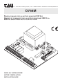
1
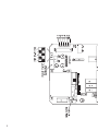
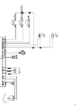
S.r.l. – Via E.Fermi, 23 Sandrigo (VI) Italy – TEL.++39444750190 FAX++39444750376 E-mail:[email protected]
D754M
SCHEDA COMANDO PER UN MOTORE MONOFASE 230 VAC
ARMOIRE DE COMMANDE POUR UN MOTEUR MONOPHASÉ 230 V.C.A.
230 VAC SINGLE-PHASE MOTOR CONTROL BOARD
GUIDA ALL’ INSTALLAZIONE
NOTICE D’INSTALLATION
INSTALLATION GUIDE
1
2
3
INSTALLAZIONE - INSTALLATION - INSTALLATION
I
L’INSTALLAZIONE DELL’APPARECCHIATURA DEVE ESSERE EFFETTUATA “A REGOLA D’ARTE “ DA PERSONALE QUALIFICATO COME DISPOSTO
DALLA LEGGE 46/90.
N.B.: si ricorda l’obbligo di mettere a massa l’impianto nonché di rispettare le
normative sulla sicurezza in vigore in ciascun paese.
LA NON OSSERVANZA DELLE SOPRAELENCATE ISTRUZIONI PUO’ PREGIUDICARE IL BUON FUNZIONAMENTO DELL’APPARECCHIATURA E CREARE PERICOLO PER LE PERSONE, PERTANTO LA CASA COSTRUTTRICE” DECLINA OGNI
RESPONSABILITA’ PER EVENTUALI MAL FUNZIONAMENTI E DANNI DOVUTI ALLA
LORO INOSSERVANZA.
F
L’INSTALLATION DE L’EQUIPEMENT DOIT ETRE REALISEE “SELON
LES REGLES E L’ART” PAR LE PERSONNEL COMPETENT AYANT LES QUALITES
REQUISES PAR LA LOI 46/90
N.B.: nous rappelons l’obligation de mettre l’installation à terre et de respecter les
normes de sècuritè en vigeur dans le pays d’installation.
LA NON OBSERVATION DES INSTRUCTIONS POURRAIT COMPROMETTRE LE
BON FONCTIONNEMENT DE L’APPAREILLAGE ET CREER UN DANGER POUR
LES PERSONNES, PAR CONSEQUENT LA MAISON DECLINE TOUTE
RESPONSABILITE POUR D’EVENTUALLES DETERIORATIONS DUES A UNE
UTILISATION NON APPROPRIEE OU NON CONFORME AU MODE D’EMPLOI.
GB
THE EQUIPMENT MUST BE INSTALLED “EXPERTLY” BY QUALIFIED
PERSONNEL AS REQUIRED BY LAW 46/90
N.B.: It is compulsory to earth the system and to observe the safety regulations that
are in force in each country.
IF THESE ABOVE INSTRUCTION ARE NOT FOLLOWED IT COULD PREJUDICE
THE PROPER WORKING ORDER OF THE EQUIPMENT AND CREATE HAZARDOUS
SITUATIONS FOR PEOPLE. FOR THIS REASON THE “MANUFACTURER”
DECLINES ALL RESPONSABILITY FOR ANY MALFUNCTIONING AND DAMAGES
THUS RESULTING.
4
INDICE
CONTENTS
INDEX
Pag. 6-7
Italiano
Pag. 8-9
Français
Pag. 10-11
English
Pag. 13
Garanzia
5
Italiano
LOGICA CON MICROPROCESSORE
LED DI AUTODIAGNOSI
PROTEZIONE INGRESSO LINEA CON FUSIBILE
LIMITATORE DI COPPIA ELETTRONICO INCORPORATO
CONTROLLO ELETTRONICO SPUNTO DI LAVORO
CIRCUITO LAMPEGGIO INCORPORATO
CONNETTORE PER SCHEDA RICEVENTE
•
•
•
•
•
•
•
COLLEGAMENTI ALLA MORSETTIERA
1-2
Ingresso alimentazione 230 Vac 50Hz.
3-4
uscita lampeggiante 230 Vac 50W max. Il segnale fornito è già opportunamente
modulato per l’uso diretto.La frequenza di lampeggio è leggermente superiore in
fase di chiusura.
5-6-7
8-9
uscita motore M1 monofase 230 Vac, 300 W max.
comune = 6; fase apertura = 5;fase chiusura = 7;
collegare il condensatore tra i morsetti 5 e 7.
uscita 24Vac,10W per l’alimentazione di fotocellule, ricevitori esterni, etc
11-12 uscita 24 Vac Max 3W per l’alimentazione relè aux per luce di cortesia. La luce si
accende ad inizio manovra e si spegne dopo 3 min circa.
15-16 Ingresso finecorsa di chiusura (contatto normalmente chiuso); 15 = COMUNE
Ingresso finecorsa di apertura (contatto normalmente chiuso); 15 = COMUNE
15-18 Ingresso pulsante STOP (contatto Normalmente Chiuso); il suo intervento provoca l’arresto del’automazione. Al comando successivo l’automazione va in apertura. 15 = COMUNE.
15-19 Ingresso bordo sensibile (costa meccanica) o altri dispositivi di sicurezza e/o
altro (fotocellule, coste meccaniche, etc.) 15 = COMUNE.
15-20 ingresso pulsante APRI-CHIUDI (contatto Normalmente Aperto) per le modalità
d’uso fare riferimento ai dip-switch nr.2 e 3, 15 = COMUNE.
21-22 Ingresso antenna 21 = SEGNALE. 22 = MASSA.
23-24 uscita 2° CANALE RADIO.
REGOLAZIONE LOGICHE DEL TRIMMER
T.L.
Regolazione Tempo di Lavoro: da 5 a 125 secondi.
T.C.A. Regolazione Tempo di Chiusura Automatica: da 5 a 125 secondi.(vedi dip switch
nr.1)
6
REGOLAZIONE LOGICHE DEI DIP-SWITCH
N°1
N°2
N°3
N°4
N°5
ESCLUSIONE RICHIUSURA AUTOMATICA:
OFF: esclusione richiusura automatica
ON: tempo di richiusura automatica inserito, (da regolare con il trimmer T.C.A.)
FUNZIONE 2 O 4 TEMPI:
ON: ad automazione funzionante, una serie di comandi di apertura-chiusura
induce il cancello ad una APERTURA-CHIUSURA-APERTURA-CHIUSURA,etc.
OFF: nelle stesse condizioni, la stessa serie di comandi induce il cancello ad una
APERTURA STOP-CHIUSURA-STOP-APERTURA-STOP, etc. (funzione passo-passo)
NO REVERSE:
OFF:l’automazione in fase di apertura ignora i comandi di chiusura.
ON: l’automazione si comporta secondo la regolazione del dip switch 2
FUNZIONE OROLOGIO:
OFF: è possibile utilizzare un timer (ex. settimanale) collegato all’ingresso del pulsante apre-chiude per mantenere aperto il cancello in determinate fasce orarie e
permetterne poi la richiusura automatica.
ON: l’ingresso pulsante apre-chiude mantiene il funzionamento standard.
ESCLUSIONE PRELAMPEGGIO:
OFF: il lampeggiante inizia il lampeggio quando viene alimentata l’automazione.
ON: il lampeggiante inizia il lampeggio alcuni secondi prima che venga alimentata
l’automazione
REGOLAZIONE DELLA POTENZA
La regolazione della potenza viene effettuata tramite un regolatore a quattro posizioni, che
va da 1 (minima potenza) a 4 (massima potenza). Agendo sul dispositivo è possibile regolare direttamente dalla centrale di comando la forza degli operatori.
LED DI DIAGNOSI:
I led verdi segnalano la presenza di contatti normalmente chiusi, pertanto devono rimanere
sempre accesi se non vi sono problemi sull’impianto. I led rossi segnalano invece dei contatti normalmente aperti, quindi si accendono solamente quando vengono utilizzati (ad
eccezzione del led 1 che rimane acceso per segnalare la presenza di alimentazione).
LED ROSSO L1= Segnala la presenza di alimentazione 24
LED VERDE
LED VERDE
LED VERDE
LED VERDE
LED ROSSO
L2= Segnala il funzionamento dell’ingresso FINECORSA DI CHIUSURA
L3= Segnala il funzionamento dell’ingresso FINECORSA DI APERTURA
L4= Segnala il funzionamento del comando di STOP
L5= Segnala il funzionamento dell’ingresso BORDO SENSIBILE
L6= segnala il funzionamento del comando APRE E CHIUDE
7
Français
•
•
•
•
•
•
•
LOGIQUE AVEC MICROPROCESSEUR
DIODE ÉLECTROLUMINESCENTE D’AUTODIAGNOSTIC
PROTECTION ENTRÉE LIGNE PAR FUSIBLE
LIMITEUR DE COUPLE ÉLECTRONIQUE INCORPORÉ
CONTRÔLE ÉLECTRONIQUE COUPLE DE TRAVAIL
CIRCUIT DE CLIGNOTEMENT INCORPORÉ
CONNECTEUR POUR RÉCEPTEUR
COLLEGAMENTI ALLA MORSETTIERA
1-2
Entrée alimentation 230 V.c.a. 50 Hz.
3-4
Sortie clignotant 230 V.c.a. 50 W max. Le signal fourni est déjà modulé pour
l’utilisation directe. La fréquence de clignotement est légèrement supérieure en
phase de fermeture.
5-6-7
8-9
Sortie moteur M1 monophasé 230 V.c.a., 300 W max.
commun = 6; phase ouverture = 5 ; phase fermeture = 7
connecter le condensateur entre les bornes 5 et 7.
Sortie 24V.c.a.,10 W pour l’alimentation de photocellules, récepteurs extérieurs, etc.
11-12 Sortie 24 V.c.a. Max 3 W pour l’alimentation relais auxiliaire pour éclairage automatique.
La lumière s’allume au début de la manœuvre et s’éteint au bout de 3 min. environ.
15-16 Entrée microinterrupteur de fermeture (contact normalement fermé); 15 = COMMUN
Entrée microinterrupteur de ouverture (contact normalement fermé); 15 = COMMUN
15-18 Entrée bouton STOP (contact Normalement Fermé); son intervention provoque l’arrêt de
l’automatisme. À la commande successive, l’automatisme va en ouverture. 15 = COMMUN.
15-19 Entrée bord sensible (barre palpeuse mécanique) ou autres dispositifs de sécurité
et/ou autre (photocellules, barres palpeuses mécaniques, etc.). 15 = COMMUN
15-20 Entrée bouton OUVRE-FERME (contact Normalement Ouvert) pour les modalités
de fonctionnement se référer aux dip-switchs n° 2 et 3, 15 = COMMUN.
21-22 Entrée antenne 21 = SIGNAL. 22 = MASSE.
23-24 sortie 2e CANAL RADIO.
RÉGLAGES LOGIQUES TRIMMER
T.L.
réglage Temps de Travail : de 5 à 125 secondes.
T.C.A. réglage Temps de Fermeture Automatique : de 5 à 125 secondes.
(voir dip-switch n° 1)
8
RÉGLAGES LOGIQUES DIP-SWITCHS
N°1
N°2
N°3
N°4
N°5
EXCLUSION REFERMETURE AUTOMATIQUE:
OFF: exclusion refermeture automatique
ON: temps de refermeture automatique activé (à régler avec le trimmer T.C.A.)
FONCTION 2 OU 4 TEMPS:
ON: avec l’automatisme en fonction, une série de commandes d’ouverturefermeture porte le volet à effectuer une OUVERTURE-FERMETURE-OUVERTUREFERMETURE, etc.
OFF: dans les mêmes conditions, la même série de commandes porte le volet à
effectuer une OUVERTURE-STOP-FERMETURE-STOP-OUVERTURE-STOP, etc.
(fonction pas-à-pas)
NO REVERSE :
OFF: l’automatisme en phase d’ouverture ignore les commandes de fermeture.
ON: l’automatisme se comporte comme l’établit le dip-switch 2
FONCTION HORLOGE:
OFF: il est possible d’utiliser un temporisateur (ex. hebdomadaire) connecté sur
l’entrée du bouton ouvre-ferme pour maintenir le portail ouvert dans certaines
plages horaires et pour en permettre ensuite la refermeture automatique.
ON: l’entrée bouton ouvre-ferme maintient le fonctionnement standard.
EXLUSION PRÉCLIGNOTEMENT:
OFF: le clignotement commence quand l’automatisme est alimenté.
ON: le clignotement commence quelques secondes avant que l’automatisme soit alimenté.
RÉGLAGE PUISSANCE
Le réglage de la puissance s’effectue à l’aide d’un dispositif de réglage à quatre positions,
qui va de 1 (puissance minimum) à 4 (puissance maximum). En agissant sur le dispositif, il
est possible de régler la force des opérateurs directement à partir de l’armoire de commande.
DEL DE DIAGNOSTIC
Les diodes électroluminescentes vertes signalent la présence de contacts normalement
fermés ; ils doivent par conséquent rester toujours allumés s’il n’y a pas de problèmes sur
l’installation. Les del rouges signalent au contraire des contacts normalement ouverts ; elles
ne s’allument donc que lorsqu’ils sont activées (à part la del 1 qui reste allumée pour signaler
la présence de l’alimentation).
LED ROUGE L1=Signale la présence d’alimentation 24
LED VERTE
LED VERTE
LED VERTE
LED VERTE
LED ROUGE
L2=Signale le fonctionnement de l’entrée MICROINTERRUPTEUR DE FERMETURE
L3=Signale le fonctionnement de l’entrée MICROINTERRUPTEUR DE OUVERTURE
L4=Signale le fonctionnement de la commande de STOP
L5=Signale le fonctionnement de l’entrée BORD SENSIBLE
L6=Signale le fonctionnement de la commande OUVRE ET FERME
9
English
MICROPROCESSOR-CONTROLLED LOGIC
DIAGNOSTIC LEDS
LINE INPUT PROTECTION WITH FUSE
INCORPORATED ELECTRONIC TORQUE LIMITER
ELECTRONIC PEAK LOAD CONTROL
INCORPORATED FLASHING LIGHT
CONNECTOR FOR RECEIVER BOARD
•
•
•
•
•
•
•
CONNECTION TO THE TERMINAL BOARD
1-2
power supply input 230 Vac 50Hz.
3-4
flashing light output 230 Vac 50W max. The signal delivered is already suitably
modulated for use as it is. The flashing frequency is slightly faster during closing.
5-6-7
8-9
230 Vac single-phase motor M1 output, 300 W max.
common = 6; opening = 5; closing = 7
connect the capacitor between terminals 5 and 7.
24Vac,10W output for powering photocells, outside receivers, etc.
11-12 24 Vac Max 3W output for powering aux relay for courtesy light. The light comes
on when the maneuver starts and goes off after about 3 minutes.
15-16 Input for closing limit switch (normally-closed contact); 15 = COMMON
Input for opening limit switch (normally-closed contact); 15 = COMMON
15-18 input for STOP button (normally-closed contact); pressing this button causes the
automation to stop.
The next command always triggers an opening cycle. 15 = COMMON
15-19 Input for pressure-sensitive edge (mechanical edge) or other safety and/or other
devices (photocells, mechanical edges, etc.) 15 = COMMON
15-20 input for OPEN/CLOSE button (normally-open contact); for its use, refer to DIP
switches 2 and 3, 15 = COMMON.
21-22 Input for aerial 21 = SIGNAL. 22 = EARTH.
23-24 output for 2nd RADIO CHANNEL
LOGIC ADJUSTMENTS TRIMMER
T.L.
adjusts operating time: from 5 to 125 seconds.
T.C.A. adjusts automatic re-closing time; from 5 to 125 seconds (see dip switch nr.1)
10
LOGIC ADJUSTMENTS DIP-SWITCHES
N°1
N°2
N°3
N°4
N°5
DISABLES AUTOMATIC RE-CLOSING:
OFF: the automatic closing after opening is disabled.
ON: automatic timer-controlled re-closing enabled (adjustable with the trimmer T.C.A.).
2- OR 4- STAGE OPERATION:
ON: with the automation enabled, a series of opening and closing commands
induces the shutter to perform an OPENING-CLOSING-OPENING-CLOSING type
of sequence.
OFF: in the same conditions, the same set of commands induces the shutter to
perform an OPENING STOPPING-CLOSING-STOPPING-OPENING-STOPPING
type of cycle (step-by-step operation)
NO REVERSE:
OFF: during opening the automation ignores any closing commands.
ON: the automation’s behavior depends on the position of dip switch 2.
TIMER FUNCTION:
OFF: a timer (e.g. weekly) can be connected to the input for the open/close button
to have the gate open at certain times of day and enable its subsequent automatic
closing again.
ON: the input for the open/close button continues to function normally.
PREFLASHING ON/OFF OPTION:
OFF: flashing begins when the automation is enabled.
ON: flashing begins a few seconds before the automation is enabled.
POWER CONTROL
The power is adjusted by means of a control with four positions, ranging from 1 (minimum
power) to 4 maximum power. This device is used to adjust the force of the operator directly
from the control unit.
DIAGNOSTIC LEDS
The green leds indicate the presence of normally-closed contacts, so they will always remain
on if there are no problems in the system. The red leds, on the other hand, indicate normallyopen contacts so they only come on if they are in use (with the exception of led 1 which
remains on to indicate that the circuit is powered).
LED RED
LED GREEN
LED GREEN
LED GREEN
LED GREEN
LED RED
L1= indicates the presence of the power supply 24
L2= Indicates the enabling of the input for the CLOSING LIMIT SWITCH
L3= Indicates the enabling of the input for the OPENING LIMIT SWITCH
L4= Indicates the enabling of the STOP command
L5= Indicates the enabling of the input for the PRESSURE-SENSITIVE EDGE
L6=indicates the enabling of the OPEN/CLOSE command
11
12
Garanzia TAU: condizioni generali
ITALIANO
Il cliente TAU ha diritto ad usufruire della garanzia qualora abbia compilato ed inviato entro 10 giorni dalla data di installazione dell’apparecchiatura l’apposito certificato.
La garanzia della TAU ha durata di un anno dalla data di installazione dei prodotti indicata nel certificato di garanzia e decadrà se, dalla
data di produzione dell’apparecchiatura, sono trascorsi più di 18 mesi. La data di fabbricazione è stampata, sotto forma di codice, su
un’etichetta adesiva al prodotto.
La contraffazione o la cancellazione della data impressa sul prodotto annulla la validità della garanzia.
La garanzia comprende la riparazione con sostituzione gratuita (franco sede TAU) delle parti che presentano difetti di lavorazione o vizi di
materiale riconosciuti dalla TAU.
In caso di intervento a domicilio, anche nel periodo coperto da garanzia, l’utente è tenuto a corrispondere il “Diritto fisso di chiamata” per
spese di trasferimento a domicilio, più manodopera.
La garanzia decade nei seguenti casi:
• Qualora il guasto sia determinato da un impianto non eseguito secondo le istruzioni fornite dall’azienda all’interno di ogni confezione;
• Qualora non siano stati impiegati tutti componenti originali TAU per l’installazione della automazione;
• Qualora i danni siano causati da calamità naturali, manomissioni, sovraccarico di tensione, alimentazione non corretta, riparazioni
improprie, errata installazione, o altre cause non imputabili alla TAU.
La riparazione o la sostituzione dei pezzi durante il periodo di garanzia non comporta un prolungamento del termine di scadenza della
garanzia stessa.
IMPORTANTE: durante l’installazione è fondamentale che l’installatore compili esattamente il certificato di garanzia. Il certificato dovrà
essere inviato alla TAU entro 10 giorni dalla data di installazione. In questo modo l’utente avrà la certezza che il prodotto installato potrà
godere della garanzia per la durata di 12 mesi.
Nel caso di un impianto comprendente più prodotti TAU soggetti a garanzia raggruppare le etichette adesive in un unico certificato di
garanzia o spedire in un’unica busta chiusa tutti i certificati di garanzia relativi ai prodotti utilizzati nell’impianto.
Garantie TAU: conditions générales
FRANÇAIS
Le client TAU a le droit de bénéficier de la garantie s’il a rempli et renvoyé dans les 10 jours qui suivent la date d’installation de l’appareil
le certificat de garantie prévu à cet effet.
La garantie TAU a une durée d’un an à compter de la date d’installation des produits indiqués dans le certificat de garantie et perdra effet
si plus de 18 mois
se sont écoulés par rapport à la date de production de l’automatisme. La date de fabrication est imprimée sous forme de code sur une
étiquette adhésive collée sur le produit. La contrefaçon ou l’effacement de la date imprimée sur le produit annule la validité de la garantie.
La garantie comprend la réparation avec remplacement gratuit (franco au siège TAU) des parties présentant des défauts de fabrication ou
de matériau reconnus par TAU. En cas d’intervention à domicile, y compris durant la période couverte par la garantie, l’utilisateur est tenu
de payer le «Droit fixe d’appel»
pour les frais de transfert à domicile, plus la main d’œuvre.
La garantie n’est plus applicable dans les cas suivants:
• Si la panne est due à une installation qui n’a pas été effectuée selon les instructions fournies par le constructeur à l’intérieur de chaque
emballage;
• S’il a été utilisé des composants non originaux TAU pour l’installation de l’automatisme;
• Si les dommages ont été causés par des calamités naturelles, des modifications, une surcharge de tension, une alimentation non
correcte, des réparations impropres, une installation erronée ou d’autres causes non imputables à TAU.
La réparation ou le remplacement des pièces dans la période couverte par la garantie n’entraînent pas le report de la date d’expiration de
la garantie.
IMPORTANT: Au moment de l’installation il est fondamental que l’installateur remplisse intégralement ce certificat de garantie. Le
certificat devra être envoyé à TAU dans les 10 jours qui suivent la date d’installation. De cette manière, l’utilisateur aura la certitude que le
produit installé pourra bénéficier d’une garantie de 12 mois.
Si une installation comprend plusieurs produits TAU sujets à garantie, regrouper les étiquettes adhésives sur un seul certificat de garantie
ou expédier dans une seule enveloppe fermée tous les certificats de garantie relatifs aux produits utilisés dans l’installation.
The TAU Guarantee: general conditions
ENGLISH
TAU customers may claim under this guarantee as long as they have filled in and sent the guarantee certificate within 10 days from the
date of installation
of the equipment.
The TAU guarantee lasts one year from the date of installation of the products indicated in the guarantee certificate and will become null
if more than 18 months have elapsed since the date of production of the equipment. The date of production is printed in code on an
adhesive label attached to the product. Any alterations or cancellation of the date printed on the product will cause the guarantee to
become null and void.
The guarantee covers the repair or replacement (free delivery to TAU) of the components which TAU recognises have manufacturing
defects or faulty materials. If work is carried out at the customers facilities, even during the guarantee period, the user must pay the “Fixed
Call-out charge” for travelling expenses, plus labour costs.
The guarantee will become null and void in the following cases:
• If the fault was determined by a system that was not installed according to the instructions provided by the company inside each pack;
• If any non-original TAU components were used to install the automatic system;
• If the damage was caused by natural disaster, tampering, voltage overload, incorrect power input, incorrect repairs, incorrect installation
or other reasons out of TAU’s control.
Repair or replacement of pieces during the guarantee period does not extend the expiry date of the guarantee.
IMPORTANT: during the installation, the installer must correctly fill in guarantee certificate. The certificate must be sent to TAU within 10
days from the date of installaiton. The user will thus be sure that the installed product will enjoy a 12 month guarantee.
In case of a system containing several TAU products under guarantee, collect the sticky labels in a single guarantee certificate and send
all the guarantee certificates concerning the products used in the plant in a closed envelope.
13
NOTE:
14
NOTE:
15
16
REV.02 DEL 04.02 n.r.ar/sch/uso/k754M