1
USER GUIDE
p.8
___________________________________________________________________________________________________
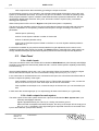
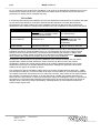
If the processor is placed at the mixing position a standard shielded cable is utilizable but without using
the shield as a conductor. The shield should be wired to the XLR4 chassis on the LS TDcontroller side by
the plug specific soldering pin (electrically linked to the TD chassis). Do not wire the shield on the amp
rack side as you may then create ground loops.
It is strongly advised to protect the amplifiers from short-circuits in the sense lines. It is recommended that
a 1 kOhm resistor with a power rating of at least three watts be inserted as close as possible to the output
terminals of the amps.
II.4.b. Connecting the audio outputs
Output stages are designed to withstand low load impedances, so that a large number of paralleled
devices or amplifiers can be driven ; however operating under load impedances lower than 600 Ohms
should be avoided (refer to the input impedance values stated the relevant manufacturers, if no precise
data are available 10 kOhms can be considered as a standard minimum value).
Please note that the levels on the two signal pins of the output are not the same relative to electric
ground : this is quite normal and does not affect the balanced nature of the output (this is intentional and
is concerned with stability considerations)
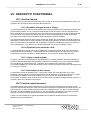
II.5. Parameter cards
II.5.a. Identification
The internal parameter card is an important part of the LS TDcontroller ; it contains sections whose
adjustments are specific to the type of LSub to be used. For that reason, it is very important to use an
appropriate parameter card : failure to do so will degrade acoustical performance and possibly result in
damage to the speakers.
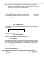
For easy identification, each parameter card has a label attached which can be seen from outside the
controller, through a small front panel window (inside the TD border). Five characters are used to identify
the card reference, according to a code explained below :
the first 2 characters are according to the type of LSub cabinets to which the card is dedicated :
the first character is 1 in case of LS1500, 2 in case of LS2000, the second character is a
complementary identification code for the cabinet (revision number).
the last 3 characters are relative to the crossover characteristics.
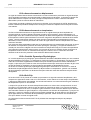
II.5.b. Changing the parameter card
Replacement of the internal parameter card can be done easily by the user, as follows :
1. unplug AC line and all input / output connectors
2. unfasten the 4 screws placed on the sides of the top cover and remove the cover by sliding it
backwards
3. remove the parameter card , holding it on each side and lifting it gently to disengage the card
from the two connectors
4. put the new card inside, with its identification label leaning against the second front panel, and
plug it in by pressing downward in front of the two connectors, taking care to align it correctly.
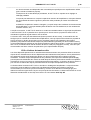
5. reposition the cover by sliding it from rear to front, its front edge coming against the aluminium
front panel and above the second steel front panel.
6. fasten and secure the cover with the 4 side screws
User manual
Release : 2.1
Date : 05/01/2005
LS TDcontroller