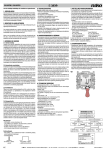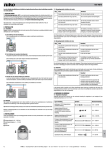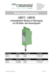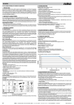
1
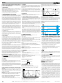
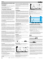
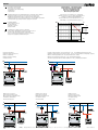
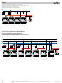
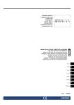
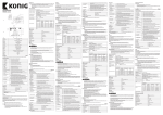
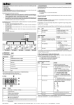
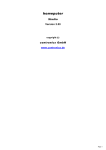
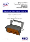
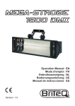
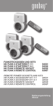
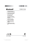
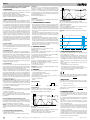
05-728
Lees de volledige handleiding vóór installatie en ingebruikname.
Bewaar deze handleiding zorgvuldig voor later gebruik.
1. BESCHRIJVING
Intensiteitsregeling (‘dimming’) van alle regelbare resistieve en inductieve
belastingen, met uitzondering van fluorescentielampen en capacitieve
belastingen (elektronische transformatoren...).
Resistieve belastingen: gloeilampen, 230V-halogeenlampen...
Inductieve belastingen: ferromagnetische (gewikkelde) transformatoren
Resistieve en inductieve lasten mogen gemengd worden.
2. WERKING EN GEBRUIK
De dimmer 05-728 werkt met een triac (fase-AANsnijding). De dimmer
wordt bediend op afstand door middel van één of meerdere N.O.-contacten
(170-0000X). Een korte druk op de toets schakelt het licht aan of uit (werkt
als een schakelaar). Een langere druk op de toets beveelt de dimwerking.
De regeltijd (gemeten bij gloeilampen) van een volledige cyclus bedraagt
± 4s. (min. - max. - stop). Een hernieuwde druk keert de dimrichting
om. De tijd tussen twee bedieningen moet min. 500ms. bedragen (zie
fig.1 en 2). De druktoetsen worden via een interne optocoupler met de
dimmer verbonden om storingen te vermijden. Een lamp die aangesloten
is via dimmers kan niet tot de max. lichtintensiteit gedimd worden. De
lichtopbrengst zal steeds kleiner zijn dan die van een identieke lamp die
rechtstreeks op het net aangesloten is. De dimmer is voorzien van een
systeem dat knipperen vermijdt bij plotse daling van de netfrequentie.
‘Frequentiedips’ tot 3Hz worden opgevangen door een vermindering
van de lichtintensiteit. De dimmer kan naar max. geregeld worden bij de
eerstvolgende bediening. Na inschakeling van de netspanning kan het
-afhankelijk van de netfrequentie- tot 20s. (40Hz) duren voor de dimmer
bediend kan worden.
2.1. Lokale bediening
De dimmer is voorzien van een lokale bedieningstoets op de voorkant.
Deze toets heeft dezelfde functie als de toetsen die op afstand verbonden
worden en kan gebruikt worden om de dimmer lokaal te testen of om de
geheugenfunctie (zie 2.3.) in te stellen.
2.2. Afstandsbediening
Afstandsbediening door N.O.-contacten (niet verlicht). Kort drukken voor
inschakelen/uitschakelen. Lang drukken voor opdimmen/neerdimmen.
Bij lang drukken wordt na elke onderbreking de richting omgekeerd
(opdimmen -> stop -> neerdimmen -> stop -> opdimmen -> ...). Eens de
maximumintensiteit bereikt is, blijft het niveau onveranderd, ook al wordt
de druktoets nog langer ingedrukt. Het laatste niveau wordt al dan niet in
een geheugen opgeslagen (zie 2.3.). Tot 30 N.O.-contacten (170-0000X)
kunnen in parallel aangesloten worden (max. afstand 50m). Verschillende
configuraties zijn mogelijk (zie schema's).
2.3. Geheugenfunctie
De dimmer kan zowel met als zonder geheugen gebruikt worden. Zonder
geheugenfunctie schakelt de dimmer in op max. lichtsterkte. Met geheugenfunctie schakelt de dimmer bij ingebruikneming in op min. lichtstand.
Daarna schakelt de dimmer in op de laatst ingestelde waarde.
De dimmer is standaard ingesteld met geheugenfunctie. Om deze functie
te wijzigen, volstaat het gedurende 10s. op de bedieningstoets te drukken.
Na 10s. daalt de lichtintensiteit van 100% tot 50% om aan te duiden dat de
standaardfunctie uitgeschakeld is. Los de druktoets onmiddellijk na deze
wijziging in lichtintensiteit. Herhaal deze procedure om de geheugenfunctie
weer in te schakelen. Deze functie wordt samen met de laatst ingestelde
lichtstand in een permanent geheugen bewaard. Zij gaan bij een spanningsonderbreking niet verloren.
In combinatie met Nikobus: Als de dimmer 05-728 samen met het
Nikobus-domoticasysteem gebruikt wordt, let er dan op dat de dimmer
05-728 ingesteld is zonder geheugenfunctie. Dit om te vermijden dat
de dimmer 05-728 met geheugenfunctie inschakelt als hij na een lange
stroomonderbreking opnieuw onder spanning komt. Dit is absoluut niet
aan te bevelen in combinatie met Nikobus.
2.4. Beveiligingen
Thermische beveiliging: indien de interne temperatuur 120°C overschrijdt,
zal deze beveiliging de dimmer uitschakelen. Zodra de temperatuur daalt,
is de dimmer weer regelbaar.
Softstart: de inschakelstroom wordt elektronisch beperkt.
Indien er ontstekingsproblemen zijn door zeer hoge inducties wordt de
triac uitgeschakeld. De dimmer herstart automatisch zodra de druktoets
bediend wordt.
2.5. Netaansluitingen: bovenaan van links naar rechts
Zie schema's. De twee klemmen aan de rechterzijde zijn intern doorverbonden. Draag er tijdens de installatie zorg voor dat de aansluitdraden zich
minimaal 5cm van de koelopeningen bevinden. Op geen enkel ogenblik
mogen de aansluitdraden de koelopeningen afdekken.
Opgelet: voor het inschakelen nazien of alle verbindingen goed aangespannen zijn. Bij onderhoud van de installatie moet men de druk op de
klemmen nazien. De dimmer moet in een kast met afscherming geplaatst
worden.
2.6. Sturingsaansluitingen: druktoetsbediening
Er zijn verschillende configuraties mogelijk: zie schema's:
- drukknop naar geregelde fase
- drukknop naar de fase: externe draadbrug toevoegen (niet geleverd)
2.7. Koeling
De koeling is essentieel voor een bedrijfszeker en veilig gebruik. De dimmer
produceert ±0,9% warmte t.o.v. het aangesloten verbruik. Bv. 1.000W
verlichting = 9W dissipatie. Zorg voor een aangepaste circulatie van
koele lucht t. o. v. het totaal gedissipeerd vermogen. Indien de natuurlijke
luchtcirculatie beperkt is, moet er een ventilator in de kast of in het lokaal
voorzien worden. Behoud 2cm onderlinge afstand indien meerdere dimmers
naast elkaar geplaatst worden.
Nominale omgevingstemperatuur: 35°C.
2.8. Ontstoring
Storing over de voedingskabels: de ontstoringsgraad beantwoordt aan de
Europese standaard (EN55015).
3. WAARSCHUWINGEN BIJ GEBRUIK
-Deze toestellen zijn niet geschikt voor het regelen van motoren tenzij de
specifieke veiligheidseisen door externe systemen gewaarborgd worden
(automatisch herstarten na netonderbreking is in dit geval niet toegelaten).
-Opmerking i.v.m. inductieve lasten: als de dimmer aangesloten wordt
op gewikkelde transformatoren mogen enkel transformatoren gebruikt
worden die geschikt zijn voor dimming. De transformatoren moeten min.
75% belast zijn.
-Het verbruik van ferromagnetische transformatoren moet met rendementsverlies vermeerderd worden (bv. rendement 80% = max. belasting
800W). Als het rendement niet gekend is, moet de max. belasting met
20% verminderd worden.
-Het gebruik van ringkerntransformatoren kan gebrom veroorzaken.
-De dimmer wordt door een bediening van de sturing nooit elektrisch van
het net gescheiden. Alle delen, incl. de lampen, blijven onder spanning,
ook al is het licht ‘uit’. Signalen die via het net verstuurd worden, kunnen
de werking van de dimmer storen. De storing treedt enkel op als dit
signaal over het net verstuurd wordt. De dimmer is voorzien van een
ingebouwde filter om dit effect te onderdrukken.
4. TECHNISCHE GEGEVENS
Voedingsspanning: 230V~ ±10%, frequentie 40 tot 60Hz
Afmetingen: H 89 x B 70 x D 54,5mm
Gewicht: 0,280kg
Voor de regeling van gloeilampen, halogeenlampen 230V~ en Ohmse
belastingen (max. 1.000W, min. 40W).
Voor halogeenlampen zeer lage spanning 12V~, 24V~ enz. met gewikkelde
transformatoren (E- kern) (max. 1.000VA, min. 50VA)
Ingebouwde drukknop voor bediening
Meerdere regelpunten door middel van drukknoppen N.O. (170-0000X),
max. 30
Thermische overbelastingsbeveiliging met automatische herstelfunctie
Mogelijkheid om de laatste lichtintensiteit te bewaren
Voorzien van een smeltpatroon F5AH (02- 920- 20), met vlugge werking
(volgens DIN 41660 of IEC 127- 2)
2 reservezekeringen ingebouwd
Belangrijk: de max. belasting is hoofdzakelijk afhankelijk van de omgevingstemperatuur (zie fig.4).
5. ONDERHOUD
Deze toestellen zijn gemaakt voor gebruik in volgende omstandigheden:
- een omgevingstemperatuur van 35°C
- een niet-condenserende luchtvochtigheidsgraad
- een netspanning van 230V
Regelmatig nazicht, van op zijn minst het volgende, is aangewezen na
volledige uitschakeling van de netvoeding:
- druk van de aansluitklemmen
- ventilatie
Kort <400ms = aan/uit
Lang >400ms = stijgen/dalen
Max.
Min.
3
4
5
6
7
Max.
Min.
1
2
3
4
5
6
7
8
9 10 11 12 13 14 15 16 17 18 19 20 21 22 23 24 25
s
Omschakeling van functie:
Dim op tot max. lichtsterkte en houd de drukknop ingedrukt.
Na 10s. max. licht daalt de lichtsterkte tot 50%. Los op dit moment de
drukknop (dimmer schakelt uit).
De functie is omgeschakeld.
Indien men de drukknop niet onmiddellijk loslaat, wordt de functie niet
omgeschakeld (dimmer blijft op 50%).
De laatste functie blijft behouden na spanningsonderbreking.
Voorbeeld: omschakelen van 'zonder geheugen' naar geheugenfunctie.
fig.3
Max.
50%
Mem.
Min.
1
2
3
4
5
6
7
8
9 10 11 12 13 14 15 16 17 18 19 s
6. WAARSCHUWINGEN VOOR INSTALLATIE
-- De installatie moet worden uitgevoerd door een erkend installateur en
volgens de geldende voorschriften.
-- Deze handleiding moet aan de gebruiker worden overhandigd. Het moet
bij het dossier van de elektrische installatie worden gevoegd en worden
overgedragen aan eventuele nieuwe eigenaars. Bijkomende exemplaren
zijn verkrijgbaar via de website of supportdienst van Niko. Op de Niko
website is altijd de meest recente handleiding van het product terug
te vinden.
-- T ijdens de installatie moet rekening gehouden worden met (nietlimitatieve lijst):
-- de geldende wetten, normen en reglementen.
-- de stand van de techniek op het moment van de installatie.
-- deze handleiding die alleen algemene bepalingen vermeldt en moet
worden gelezen in het kader van elke specifieke installatie.
-- de regels van goed vakmanschap.
Dit product voldoet aan alle toepasselijke Europese richtlijnen en verordeningen. Indien van toepassing, vind je de EG-verklaring van overeenstemming
met betrekking tot dit product op www.niko.eu.
7. NIKO SUPPORT
8
9 10 11 12 13 14 15 16 17 18 19 20 21 22 23 24 25
•• België: +32 3 778 90 80
•• Nederland: +31 880 15 96 00
8. GARANTIEBEPALINGEN
min 500ms
2
min 500ms
Contactgegevens en meer informatie vind je op www.niko.eu onder de
rubriek “Hulp en advies”.
Zonder geheugen:
Bij stijgen: de dimmer stopt op maximale lichtsterkte.
Bij dalen: de dimmer stopt 2s. op min. en dimt daarna opwaarts.
Een hernieuwde (lange) druk keert de dimrichting om.
fig.1
1
<300ms
Heb je twijfel? Of wil je het product omruilen in geval van een eventueel
defect? Neem dan contact op met je groothandel of de Niko supportdienst:
Druktoetsbediening
<300ms
fig.2
s
Met geheugen:
Kort drukken = aan-/uitschakelen op geheugen
Lang drukken bij 'uit'-toestand = de dimmer dimt opwaarts vanaf 0%.
Bij stijgen: de dimmer stopt op max. lichtsterkte
Bij dalen: de dimmer stopt 2s op min. en dimt daarna opwaarts.
Een hernieuwde (lange) druk keert de dimrichting om.
-- D e garantietermijn bedraagt vier jaar vanaf leveringsdatum. Als
leveringsdatum geldt de factuurdatum van aankoop van het product
door de consument. Als er geen factuur voorhanden is, geldt de
productiedatum.
-- De consument is verplicht Niko schriftelijk te informeren over het gebrek
aan overeenstemming, en dit uiterlijk binnen de twee maanden na
vaststelling.
-- In geval van een gebrek aan overeenstemming heeft de consument
alleen recht op een kosteloze herstelling of vervanging van het product,
wat door Niko bepaald wordt.
-- Niko is niet verantwoordelijk voor een defect of schade als gevolg van
een foutieve installatie, oneigenlijk of onachtzaam gebruik, een verkeerde
bediening, transformatie van het product, onderhoud in strijd met de
onderhoudsvoorschriften of een externe oorzaak zoals vochtschade
of schade door overspanning.
-- De dwingende bepalingen in de nationale wetgeving over de verkoop van
consumptiegoederen en de bescherming van consumenten in landen
waar Niko rechtstreeks of via zuster- of dochtervennootschappen,
filialen, distributeurs, agenten of vaste vertegenwoordigers verkoopt,
hebben voorrang op bovenstaande bepalingen.
nv Niko sa Industriepark West 40, BE-9100 Sint-Niklaas, Belgium — tel. +32 3 778 90 00 — fax +32 3 777 71 20 — e-mail: [email protected] — www.niko.eu
PM005-72800R14363
05-728
Veuillez lire le mode d’emploi entièrement avant l’installation et
la mise en service. Veuillez conserver ce mode d’emploi afin de
pouvoir le consulter ultérieurement.
1. DESCRIPTION
Variation de l’intensité lumineuse de toutes les charges résistives et
inductives réglables, à l’exception de lampes fluorescentes et de charges
capacitives (transformateurs électroniques…)
Charges résistives: lampes incandescentes, halogènes 230V~…
Charges inductives: transformateurs ferromagnétiques (bobinés)
Les charges résistives et inductives peuvent êtres mixtes.
2. FONCTIONNEMENT ET UTILISATION
Le variateur Niko 05-728 utilise des triacs (contrôle de phase). Ces variateurs
sont commandés à distance par un ou plusieurs contacts libres de potentiel
N.O. (170-0000X). Une brève pression sur la touche permet d’allumer ou
d’éteindre la lumière (fonctionnement comme un interrupteur). Une pression
plus soutenue commande la variation lumineuse. La durée du cycle est de
± 4s pour le réglage de lampes à incandescence (min. - max. - stop). Une
nouvelle pression inverse le sens de la variation. L’attente min. entre deux
commandes est de 500Ms (voir fig.1 et 2). La télécommande est raccordée
via un opto-coupleur interne pour éviter les interférences. Les lampes qui
sont reliées à des variateurs ne peuvent pas être allumées jusqu’à leur
niveau de luminosité max. L’intensité lumineuse max. sera toujours moins
élevée que celle d’une lampe directement connectée au réseau.
Le variateur est pourvu d’un système empêchant le scintillement lors de
brusques baisses de fréquence. Des sauts de fréquence jusqu’à 3Hz sont
rattrapés en diminuant l’intensité lumineuse. Le variateur sera replacé à
sa valeur max. dès la commande suivante. Il se peut également que dès
l’enclenchement de la tension et ce en fonction de la fréquence, le variateur
ne puisse être commandé avant 20s. (40Hz).
2.1. Commande locale
Le variateur est pourvu d’un bouton-poussoir à l’avant du boîtier pour
commande locale. Ce bouton-poussoir a la même fonction que ceux
raccordés à distance et peut servir pour un test ou la sélection de fonction
de mémorisation (voir 2.3.).
2.2. Télécommande
Commande par bouton-poussoir N.O. (non éclairé). Une pression brève
pour allumer/éteindre et une pression soutenue pour augmenter/diminuer.
L’action est inversée après chaque coupure (augmenter > arrêt > diminuer
> arrêt > augmenter > etc.). Le niveau reste inchangé une fois la valeur
max. atteinte, même si une pression est maintenue sur le bouton-poussoir.
Le dernier niveau lumineux peut être mémorisé (voir 2.3.). Jusqu’à 30
boutons-poussoirs 170-0000X peuvent être connectés en parallèle (distance max. 50m). Diverses configurations sont possibles (voir schémas).
2.3. Fonction de mémorisation
Sans mémorisation, le variateur enclenche l’éclairage à la tension max.
Avec mémorisation, le variateur se positionne à un niveau d’éclairage min.
au premier enclenchement. L’enclenchement suivant appelle la dernière
valeur régulée. Cette fonction est activée au moment de la livraison du
variateur. Il suffit de maintenir une pression de plus de 10s pour désactiver
cette fonction. L’éclairage diminue de la valeur max. à 50% pour indiquer
la désactivation de la fonction de mémorisation. Arrêter la pression dès
que le niveau d’éclairage passe à 50%. Répéter cette procédure pour
réactiver la fonction de mémorisation. Cette fonction ainsi que la dernière
valeur d’éclairage sont maintenues dans une mémoire permanente et sont
sauvegardées pendant une interruption éventuelle du secteur.
En combinaison avec le Nikobus: lorsque le variateur 05-728 est
utilisé avec le système domotique Nikobus, veillez à ce que le variateur soit
réglé sans mémorisation. Ceci est nécessaire afin d’éviter que le variateur
05-728 n’enclenche une valeur mémorisée lorsqu’il est réactivé après
une longue coupure de courant. Ceci n’est absolument pas recommandé
avec le Nikobus.
2.7. Ventilation
Une ventilation adéquate est primordiale pour un emploi fiable et sûr. Le
variateur dissipe ±0,9% de chaleur par rapport à sa charge nominale.
Exemple: 1.000W de puissance d’éclairage produit une dissipation calorifique de 9W.
Il y a donc lieu de bien ventiler l’appareil en fonction de sa charge. Si
la ventilation naturelle est réduite, veillez à placer un ventilateur dans
l’armoire de distribution ou dans le local technique. Température nominale
de fonctionnement: 35°C.
Maintenir 2cm de distance dans le sens de la largeur entre chaque variateur.
2.8. Déparasitage
Perturbations sur les câbles d’alimentation: le degré de déparasitage est
conforme aux prescriptions européennes (EN 55015).
3. AVERTISSEMENTS LORS DE L'UTILISATION
-Ces appareils ne conviennent pas pour la régulation de vitesse de moteurs
sauf si des systèmes externes garantissent les exigences de sécurité
spécifiques (le redémarrage automatique après coupure de courant est
explicitement défendu).
-Note pour charges inductives: au cas où le variateur est raccordé à des
transformateurs ferromagnétiques: n’utilisez que des transformateurs
destinés à être réglés par un variateur. Les transformateurs doivent être
chargés à un min. de 75% de la valeur nominale.
- la consommation de ceux-ci doit être augmentée par la perte de rendement
(p. ex. rendement 80% = charge max. 800W).
Diminuez la charge max. de 20% si le rendement n’est pas précisé.
-La variation de transformateurs toroïdaux peut provoquer un bourdonnement.
-Les variateurs ne sont jamais entièrement déconnectés du réseau par
la télécommande. Toutes les armatures et les lampes restent en permanence connectées au réseau même si l’éclairage est coupé. Des signaux
superposés au réseau peuvent occasionner un mauvais fonctionnement
du variateur. Ceci n’intervient uniquement que lorsque les signaux sont
envoyés sur le réseau. Un filtre est incorporé pour atténuer cet effet.
4. DONNÉES TECHNIQUES
Tension d’alimentation: 230V~ ±10%, fréquence 40 à 60Hz
Dimensions: H 89 x l 70 x P 54,5 mm
Poids: 0,280 kg
Pour le réglage de lampes à incandescence, lampes aux halogènes 230V~
et charges résistives (max. 1.000W, min. 40W)
Pour lampes aux halogènes très basse tension 12V~, 24V~ etc. avec
transformateurs bobinés (ferromagnétiques) (max. 1.000VA, min. 50VA)
Bouton-poussoir de commande incorporé
Commandes supplémentaires par bouton-poussoir N.O., (170-0000X),
max. 30
Protection contre surcharges à réarmement automatique
Possibilité de mémorisation de la dernière intensité lumineuse
Fusible incorporé F5AH (02- 920- 20), fusion rapide (suivant DIN 41660
ou IEC 127- 2)
2 fusibles de réserve incorporés
Attention: la charge max. admise est principalement fonction de la
température ambiante (voir fig.4).
2.5. Raccordement au réseau: de gauche à droite sur la partie
supérieure
Voir schémas. Les deux bornes à l’extrême droite sont pontées dans
l’appareil. Veuillez vous assurer que le câblage reste à min. 5cm de
distance par rapport à la fente d’aération. Les câbles ne peuvent obstruer
les fentes à aucun moment.
Attention: contrôlez si toutes les connections sont bien serties avant le
branchement au secteur. Vérifiez la pression des bornes à chaque entretien.
Le variateur doit être installé dans une armoire avec protection.
2.6. Raccordement de la télécommande: par bouton-poussoir
Plusieurs configurations possibles: voir schémas:
- bouton-poussoirs raccordés à la phase régulée
- bouton-poussoirs raccordés à la phase: pontage externe (non fourni)
<300ms
min 500ms
Max.
Min.
1
2
3
4
5
6
7
8
9 10 11 12 13 14 15 16 17 18 19 20 21 22 23 24 25
s
Modification du mode de fonctionnement
Variez jusqu’à la tension max. et maintenez le contact. Le niveau d’éclairage
descend jusqu’à 50% après 10s., lâchez immédiatement le contact
(variateur éteint). Le mode de fonctionnement ne sera pas modifié au cas
où le contact n’est pas lâché immédiatement (variateur à 50%).
La fonction choisie reste active après une interruption du secteur.
Exemple: modification du mode 'sans' mémorisation vers le mode 'avec'
mémorisation
fig.3
Max.
50%
Mem.
Min.
1
2
3
4
5
6
7
8
9 10 11 12 13 14 15 16 17 18 19 s
6. MISES EN GARDE CONCERNANT L’INSTALLATION
-- L’installation doit être effectuée par un installateur agréé et dans le
respect des prescriptions en vigueur.
-- Ce mode d’emploi doit être remis à l’utilisateur. Il doit être joint au dossier
de l’installation électrique et être remis aux nouveaux propriétaires
éventuels. Des exemplaires supplémentaires peuvent être obtenus sur
le site Web ou auprès du service support de Niko. Sur le site Web de
Niko, vous trouverez toujours le mode d’emploi le plus récent du produit.
-- Il y a lieu de tenir compte des points suivants pendant l’installation
(liste non limitative) :
-- les lois, les normes et les réglementations en vigueur.
-- l’état de la technique au moment de l’installation.
-- ce mode d’emploi qui stipule uniquement des dispositions générales
et doit être lu dans le cadre de toute installation spécifique.
-- les règles de l’art.
5. ENTRETIEN
Ces appareils sont conçus pour une utilisation dans les circonstances
suivantes:
- une température ambiante de 35°C
- un degré hygroscopique de l’air ne prêtant pas à la condensation
- une tension de 230V
Un entretien avec vérification minimale de ce qui suit est nécessaire
régulièrement (coupez l’alimentation préalablement):
- pression sur les contacts des bornes
- ventilation
Télécommande par bouton-poussoir:
2.4. Protections
Protection thermique: si la température interne dépasse 120°C, la protection débranche le variateur. Le variateur réagit à nouveau au contact
de télécommande dès que la température s’abaisse.
Softstart: le courant d’appel est limité électroniquement à l’enclenchement.
Le triac est débranché dans le cas d’un fonctionnement aléatoire dû à des
inductions trop importantes. Le variateur est réenclenché automatiquement
dès l’actionnement du bouton-poussoir.
Variation montante: le variateur s’arrête à la tension max.
Variation descendante: la variation s’arrête 2s. au min. pour remonter ensuite.
Un contact long, après interruption, inverse le sens de variation.
fig.2
Contact court <400ms = marche/arrêt
min 500ms
Max.
Min.
1
2
3
4
5
6
7
8
9 10 11 12 13 14 15 16 17 18 19 20 21 22 23 24 25
Avec mémorisation
Contact court = allumage/extinction au niveau mémorisé
Contact long depuis extinction = variation montante
7. SUPPORT DE NIKO
En cas de doute ou si vous voulez échanger le produit en cas de défaut
éventuel, veuillez prendre contact avec votre grossiste ou avec le service
support de Niko :
•• Belgique : +32 3 778 90 80
•• France : +33 820 20 66 25
Vous trouverez les coordonnées et de plus amples informations sur le site
www.niko.eu, sous la rubrique “Aide et conseils”.
8. DISPOSITIONS DE GARANTIE
contact long >400ms = montée/descente
Sans mémorisation
Montée: la variation s’arrête à la tension max.
Descente: la variation s’arrête 2s. au min. pour remonter ensuite.
Un contact long, après interruption, inverse le sens de variation.
fig.1
<300ms
Ce produit est conforme à l’ensemble des directives et règlements européens
applicables. Le cas échéant, vous trouverez la déclaration CE de conformité
relative à ce produit sur le site www.niko.eu.
s
-- Le délai de garantie est de quatre ans à partir de la date de livraison. La
date de la facture d’achat par le consommateur est considérée comme la
date de livraison. En l’absence de facture, la date de fabrication est valable.
-- Le consommateur est tenu de prévenir Niko par écrit de tout défaut de
conformité, dans un délai maximum de deux mois après constatation.
-- En cas de défaut de conformité, le consommateur peut uniquement
prétendre à la réparation gratuite ou au remplacement gratuit du produit,
selon l’avis de Niko. -- Niko ne peut être tenu pour responsable d’un défaut ou de dégâts
résultant d’une installation fautive, d’une utilisation impropre ou
négligente, d’une commande erronée, d’une transformation du produit,
d’un entretien contraire aux consignes d’entretien ou d’une cause
externe telle que de l’humidité ou une surtension.
-- L es dispositions contraignantes de la législation nationale ayant
trait à la vente de biens de consommation et à la protection des
consommateurs des différents pays où Niko procède à la vente directe
ou par l’intermédiaire d’entreprises sœurs, de filiales, de succursales,
de distributeurs, d’agents ou de représentants fixes, prévalent sur les
dispositions susmentionnées.
nv Niko sa Industriepark West 40, BE-9100 Sint-Niklaas, Belgium — tel. +32 3 778 90 00 — fax +32 3 777 71 20 — e-mail: [email protected] — www.niko.eu
PM005-72800R14363
05-728
Gebrauchsanleitung vor Montage und Inbetriebnahme vollständig
durchlesen. Bewahren Sie diese Gebrauchsanleitung sorgfältig für
einen späteren Gebrauch auf.
1. BESCHREIBUNG
Intensitätsregelung (‚Dimmung’) von allen regelbaren ohmschen und induktiven
Lasten unter Ausschluss von Leuchtstofflampen und kapazitiven Lasten
(elektronischen Transformatoren...).
Ohmsche Lasten: Glühlampen, Halogenlampen 230V, …
Induktive Lasten: gewickelte Transformatoren
Ohmsche und induktive Lasten dürfen gemischt betrieben werden.
2. FUNKTIONSWEISE UND ANWENDUNG
Der 05-728 Dimmer arbeitet mit einem Triac (Phasenanschnitt) und wird von
einem oder mehreren Schließerkontakten (170‑0000X) angesteuert. Ein kurzer
Druck auf die Taste schaltet das Licht ein oder aus (gleiche Funktionsweise
wie bei einem Schalter). Ein längerer Druck auf die Taste aktiviert die
Dimmfunktion. Der gesamte Dimm-Zyklus (bei Glühlampen) beträgt ±4s.
(Min. - Max. - Stop). Ein erneuter Tastendruck kehrt die Dimmrichtung um. Die
Mindestzeit zwischen zwei Bedienungen muss 500ms betragen (siehe Abb.1
und 2). Der Tasterstromkreis ist über einen internen Optokoppler galvanisch
getrennt, um Störungen zu vermeiden. Gedimmte Leuchten können nicht auf
den Maximalwert der Helligkeit gedimmt werden. Der max. Helligkeitswert
einer gedimmten Leuchte ist immer niedriger als der einer Leuchte die
direkt ans Netz angeschlossen ist. Der Dimmer enthält ein Regelsystem zur
Unterdrückung von Lichtflackern bei plötzlichen Netzfrequenzveränderungen.
Frequenzeinbrüche bis zu 3Hz werden ausgeregelt ohne Lichtintensitätsverlust.
Der Dimmer kann bei der nächsten Betätigung auf Max. geregelt werden.
Nach dem Einschalten der Netzspannung kann es je nach Netzfrequenz bis
zu 20s (bei 40Hz) dauern, bis der Dimmer bedient werden kann.
2.1. Lokale Bedienung
Der Dimmer ist an der Vorderseite mit einer Bedienungstaste ausgerüstet. Diese
hat dieselbe Funktion wie die Tasten für die externe Ansteuerung und kann
zur lokalen Prüfung des Dimmers bzw. zum Einstellen der Speicherfunktion
(siehe 2.3.) verwendet werden.
2.2. Ansteuerung
Die externe Ansteuerung erfolgt mit Schließerkontakten (nicht beleuchtet).
Drücken Sie die Taste kurz, um den Dimmer ein- oder auszuschalten.
Drücken Sie die Taste lang, um hoch- bzw. runter zu dimmen. Bei langem
Drücken wird nach jeder
Unterbrechung die Richtung umgekehrt (aufdimmen -> Stop -> runterdimmen
-> Stop -> aufdimmen -> ...). Sobald die jeweils höchste oder niedrigste
Lichtstärke erreicht wurde, bleibt das Beleuchtungsniveau unverändert, und
dies auch dann, wenn der Taster noch länger gedrückt wird. Das jeweils
letzte Beleuchtungsniveau kann gespeichert werden (siehe 2.3.). Bis zu 30
Schließerkontakten (170‑0000X) können parallelgeschaltet werden (max.
Abstand 50m). Verschiedene Konfigurationen sind möglich (siehe Schemas).
2.3. Lichtwertspeicher
Der Dimmer kann sowohl mit als auch ohne Speicherfunktion eingesetzt
werden. Ohne Speicherfunktion stellt sich der Dimmer beim Einschalten auf
das höchste Beleuchtungsniveau ein. Mit Speicherfunktion positioniert sich
der Dimmer beim ersten Einschalten auf einem min. Beleuchtungsniveau.
Danach stellt sich der Dimmer beim Einschalten auf den zuletzt eingestellten
und gespeicherten Wert ein.
Der Dimmer ist standardmäßig auf 'Speicherfunktion' eingestellt. Um diese
Funktion zu ändern, reicht es aus, die Bedienungstaste 10s. lang zu drücken.
Danach wird das Beleuchtungsniveau von 100% auf 50% gesenkt als
Bestätigung, dass die Speicherfunktion jetzt ausgeschaltet ist. Lassen Sie den
Taster nach dieser Änderung der Lichtintensität sofort los. Wiederholen Sie
das Verfahren, um die Speicherfunktion wieder einzuschalten. Diese Funktion
sowie das zuletzt eingestellte Beleuchtungsniveau werden gespeichert. Die
Einstellungen gehen auch bei einem Stromausfall nicht verloren.
In Kombination mit dem Nikobus: Wird der Dimmer zusammen mit der
Nikobus-Gebäudesystemtechnik eingesetzt, so muss darauf geachtet werden,
dass der Dimmer ohne Speicherfunktion eingestellt ist. Dies um zu vermeiden,
dass der Dimmer mit einem bestimmten Helligkeitswert eingeschaltet wird,
falls er z.B. nach einer längeren Unterbrechung wieder eingeschaltet wird.
Dies ist in der Kombination mit dem Nikobus nicht ratsam.
2.4. Sicherungen
Thermische Sicherung: Falls die Temperatur im Dimmer 120°C überschreitet,
schaltet diese Sicherung den Dimmer aus. Sobald die Temperatur gesunken ist,
wird der Dimmer automatisch wieder eingeschaltet und ist er erneut regelbar.
Softstart: Der Einschaltstrom wird elektronisch begrenzt. Bei Triggerproblemen
aufgrund sehr hoher induktiver Belastungen wird der Triac ausgeschaltet.
Drücken Sie den Taster, um den Dimmer wieder zu aktivieren.
2.5. Netzanschlüsse (oben von links nach rechts)
Siehe Schemas. Die zwei Klemmen an der rechten Seite sind intern miteinander
verbunden. Sorgen Sie bei der Installation dafür, dass die Anschlussdrähte
mindestens 5cm von den Kühlöffnung entfernt angeordnet werden. Die
Anschlussdrähte dürfen die Kühlöffnung nicht bedecken.
Achtung:Vor dem Einschalten ist zu prüfen, ob alle Schraubklemmverbindungen
fest sitzen. Bei der Wartung der Anlage ist der feste Sitz der Drähte in
den Klemmen zu kontrollieren. Der Dimmer muss in einem Metallschrank
(Abschirmung) installiert werden.
2.6. Steueranschlüsse: (tasterbedienung)
Es sind verschiedene Konfigurationen möglich (siehe Schemas):
- Taster verdrahtet mit gedimmter Phase
- Taster verdrahtet mit Phase: externe Drahtbrücke einsetzen (nicht mitgeliefert)
2.7. Kühlung
Die Kühlung ist für einen betriebssicheren Gebrauch von äußerster Wichtigkeit.
Der Dimmer erzeugt ca. 0,9% Wärme je nach dem angeschlossenen Verbrauch.
Zum Beispiel: 1.000W Beleuchtung = 9W Wärmeverluste. Sorgen Sie
für eine auf den gesamten Energieverbrauch abgestimmte Umwälzung
von kühler Luft. Falls die natürliche Luftumwälzung beschränkt ist, muss
ein Ventilator im Schrank bzw. im Raum vorgesehen werden. Nominale
Umgebungstemperatur: 35°C.
Falls mehrere Dimmer nebeneinander montiert werden, ist ein Zwischenabstand
von 2cm einzuhalten.
2.8. Entstörung
Störung über die Netzkabel: Der Entstörungsgrad entspricht dem europäischen
Standard (EN55015).
3. WARNHINWEISE
-Diese Geräte sind nicht zur Regelung von Motoren geeignet, es sei denn,
dass externe spezifische Sicherheitsvorkehrungen getroffen wurden, die z.B.
ein ein automatisches Anlaufen des Motors nach einem Spannungsausfall
verhindern).
-Hinweis in Bezug auf induktive Lasten: Wird der Dimmer bei gewickelten
Transformatoren verwendet, so dürfen nur Transformatoren, die zum Dimmen
geeignet sind, eingesetzt werden. Die Belastung der Transformatoren muss
mindestens 75% sein.
- Der Eigenverbrauch der gewickelten Transformatoren muss als Verlustleistung
bei der Berechnung der Gesamtleistung berücksichtigt werden (1000W
Dimmer, 1000W Trafo – 200W (10%) Eigenverbrauch = 800W max. Last).
Falls der Wirkungsgrad nicht bekannt ist, so darf die höchste anschließbare
Belastung nur 20% unter der Trafoleistung liegen.
-Bei Verwendung von Ringkerntransformatoren können Brummgeräusche
auftreten.
- Der Dimmer wird durch die Bedienung oder Ansteuerung niemals elektrisch
vom Netz getrennt. Alle Teile, inkl. der Lampen, bleiben folglich spannungsführend, auch dann, wenn das Licht 'ausgeschaltet' ist. Rundsteuersignale,
die auf das Stromversorgungsnetz eingekoppelt werden, können die Funktion
des Dimmers beeinträchtigen. Diese Störungen treten nur dann auf, wenn
das Rundsteuersignal über das Stromversorgungsnetz gesandt wird. Der
Dimmer enthält jedoch einen Filter, um diese Störung einzuschränken.
4. TECHNISCHE DATEN
Versorgungsspannung: 230V~ ±10%, Frequenz 40 bis 60Hz
Abmessungen: H 89 x B 70 x T 54,5mm
Gewicht: 0,280kg
Für das Dimmen von Glühlampen, Halogenlampen 230V~ und ohmschen
Lasten (max. 1.000W, min. 40W)
Für NV-Halogenlampen 12V~ - 24V~ usw. mit gewickelten Transformatoren
(E- Kern) (max. 1.000VA, min. 50VA)
Eingebauter Bedientaster.
Mehrere Bedienstellen durch Tasteransteuerung (Schließerkontakten
170‑0000X) möglich, max. 30.
Thermische Überlastsicherung mit automatischem Reset.
Helligkeits- Speicher.
flinke Schmelzsicherung F5AH (02- 920- 20) (gemäß DIN 41660 oder
IEC 127- 2).
2 eingebaute Ersatzsicherungen.
Wichtig: Die max. Belastung hängt hauptsächlich von der Umgebungstemperatur ab (siehe Abb. 4).
5. WARTUNG
Diese Geräte können unter folgenden Bedingungen eingesetzt werden:
- Umgebungstemperatur von 35°C
- nicht-kondensierende Luftfeuchte
- Netzspannung 230V~
Folgende Punkte sollten regelmäßig kontrolliert werden (vorher ist das Netz
komplett allpolig abzuschalten):
- Fester Sitz der Anschlussklemmen
- Lüftung (Verschmutzung)
Tasterbedienung:
Kurz <400ms = an/aus
Lang > 400ms = dimmen rauf / runter
Ohne Speicherfunktion:
-Raufdimmen: Der Dimmer stoppt auf dem höchsten Lichtniveau.
-Runterdimmen: Der Dimmer stoppt 2s. auf dem untersten Lichtniveau,
danach dimmt er wieder rauf.
-Ein erneuter (langer) Tastendruck kehrt die Dimmrichtung um
Abb.1
<300ms
min 500ms
Max.
Min.
1
2
3
4
5
6
7
8
9 10 11 12 13 14 15 16 17 18 19 20 21 22 23 24 25
s
Mit Speicherfunktion:
Kurzer Tastendruck = Dimmer stellt sich beim Einschalten auf das jeweils
gespeicherte Lichtniveau ein.
Langer Kontakt bei 'ausgeschaltetem' Dimmer = Anstieg der Lichtstärke ab 0%
Raufdimmen: Der Dimmer stoppt auf dem höchsten Lichtniveau.
Runterdimmen: Der Dimmer stoppt 2s auf dem untersten Lichtniveau und
danach dimmt er wieder rauf.
Ein erneuter (langer) Tastendruck kehrt die Dimmrichtung um.
Abb.2
<300ms
min 500ms
Max.
Min.
1
2
3
4
5
6
7
8
9 10 11 12 13 14 15 16 17 18 19 20 21 22 23 24 25
s
Umschaltung der Funktion
Dimmen Sie bis zum höchsten Lichtniveau und lassen Sie den Taster gedrückt.
Nach 10s. wird das Lichtniveau von jeweils 100% auf 50% gesenkt. Lassen
Sie den Taster jetzt los.
Die Speicherfunktion ist umgeschaltet.
Wenn Sie den Taster nicht sofort loslassen, wird die Funktion nicht umgeschaltet.
Die Speicherfunktion ist spannungsausfallsicher gespeichert.
Beispiel: Umschaltung von 'ohne Speicherfunktion' auf 'mit Speicherfunktion'.
Abb.3
Max.
50%
Mem.
Min.
1
2
3
4
5
6
7
8
9 10 11 12 13 14 15 16 17 18 19 s
6. WARNHINWEISE FÜR DIE INSTALLATION
-- Die Installation darf ausschließlich von einer Elektrofachkraft unter
Berücksichtigung der geltenden Vorschriften ausgeführt werden.
-- Diese Gebrauchsanleitung muss dem Benutzer ausgehändigt werden. Die
Gebrauchsanleitung ist den Unterlagen der elektrischen Anlage beizufügen
und muss auch eventuellen neuen Besitzern ausgehändigt werden.
Zusätzliche Exemplare erhalten Sie über die Website von Niko oder über
den Kundendienst von Niko. Die neueste Version der Gebrauchsanleitung
erhalten Sie immer auf der Niko-Website.
-- Beachten und berücksichtigen Sie bei der Installation unter anderem
folgende Punkte:
-- die gültigen Gesetze, Normen und Richtlinien.
-- den Stand der Technik zum Zeitpunkt der Installation.
-- die in dieser Gebrauchsanleitung aufgeführten Anweisungen, wobei
diese Gebrauchsanleitung nur allgemein gültige Bestimmungen enthält,
die für jede Anlage spezifisch angewendet werden müssen.
-- die allgemein anerkannten Regeln fachmännischer Arbeit.
Dieses Produkt erfüllt alle anwendbaren europäischen Richtlinien und
Verordnungen. Die für dieses Produkt zutreffende EG-Konformitätserklärung
erhalten Sie gegebenenfalls unter www.niko.eu.
7. NIKO UNTERSTÜTZUNG
Bei Zweifel oder falls Sie bei einem eventuellen Defekt des Produkts noch
Fragen bezüglich des Umtausches haben, dann nehmen Sie bitte Kontakt auf
mit dem Kundendienst von Niko (Belgien: +32 3 778 90 80) oder wenden Sie
sich an Ihren Großhändler. Kontaktdaten und weitere Informationen erhalten
Sie im Internet unter www.niko.eu in der Rubrik “Unterstützung und Beratung”.
8. GARANTIEBEDINGUNGEN
-- Der Garantiezeitraum beträgt vier Jahre ab Lieferdatum. Als Lieferdatum gilt
das Rechnungsdatum zum Zeitpunkt des Kaufs durch den Endverbraucher.
Falls keine Rechnung mehr vorhanden ist, gilt das Produktionsdatum.
-- Der Endverbraucher ist verpflichtet, Niko schriftlich über einen
Produktmangel innerhalb von zwei Monaten nach dessen Feststellung
zu informieren.
-- Im Falle eines Mangels hat der Endverbraucher nur Recht auf kostenlose
Reparatur oder Ersatz des Produkts. Eine Entscheidung darüber obliegt
allein Niko.
-- Niko ist nicht für Mängel oder Schäden verantwortlich, die durch fehlerhafte
Installation, nicht bestimmungsgemäßen oder unsachgemäßen Gebrauch,
durch falsche Bedienung, Anpassen/Ändern des Produktes, infolge von
unsachgemäßer Wartung entgegen den Wartungsvorschriften oder die
sich aus äußeren Umständen, wie beispielsweise infolge Feuchtigkeit
oder Überspannung, ergeben.
-- Zwingende Vorschriften der nationalen Gesetzgebung bezüglich des
Verkaufs von Konsumgütern und zum Verbraucherschutz haben vor den
obigen Bestimmungen Vorrang in den Ländern, in denen Niko direkt oder
über seine Neben- oder Tochtergesellschaften, Filialen, Vertriebsstellen,
Agenten oder über feste Vertreter verkauft.
nv Niko sa Industriepark West 40, BE-9100 Sint-Niklaas, Belgium — tel. +32 3 778 90 00 — fax +32 3 777 71 20 — e-mail: [email protected] — www.niko.eu
PM005-72800R14363
05-728
Read the complete manual before carrying out the installation
and activating the system. Keep the manual for future reference.
Interference across the feeder cables: interference suppression meets the
European standard EN55015.
1. DESCRIPTION
3. USAGE WARNINGS
Regulating the intensity (‘dimming’) of all dimmable resistive and inductive
loads with the exception of fluorescent lights and capacitive loads (electronic transformers…).
Resistive loads: incandescent lamps, 230V halogen lamps, ...
Inductive loads: ferromagnetic (wound) transformers
Resistive and inductive loads can be mixed.
2. OPERATION AND USE
The dimmer 05-728 operates with triacs (phase control). The dimmer is
remotely operated by one or more N.O.-contacts (170-0000X). A short
press on the key switches the light on or off (operates as a switch). A longer
press on the key operates the dimming of the light. The duration of a cycle
is ±4s. for the regulation of incandescent lamps (min. - max. - stop). A
new press reverses the dim direction. The time between two contacts
must at least be 500ms. (fig.1 and 2). The push buttons are connected to
the dimmer through an internal opto-coupler to avoid interference. Lamps
connected via dimmers can’t be dimmed to the max. light intensity. The
light intensity will always be less in comparison with an identical lamp
which is connected directly to the mains. The dimmer is provided with a
system that avoids blinking in case of a sudden dips in the mains frequency.
‘Frequency dips’ up to 3Hz are absorbed by reducing the light intensity.
The dimmer can be dimmed to max. at the next operation. Depending on
the mains frequency, it may take up to 20s. (40Hz) before the dimmer can
be operated after switching on the mains.
2.1. Local operation
The dimmer is provided with a push button on the front panel. This button
has the same control function as the remote ones and can be used for
local testing or setting the memory function (see 2.3.).
2.2. Remote control
Remote control operation with N.O.-contacts (non-lit). Press briefly to switch
on/off. Press long to increase/decrease. When pressing long, the dimming
direction is reversed after each interruption (dim up -> stop -> dim down
-> stop -> dim up -> ...). Once the max. level of light intensity is reached,
this level will stay unchanged, even if the push button is still pressed. The
last level can be stored in a memory. (see 2.3.). Up to 30 N.O.-contacts
(170-0000X) can be connected in parallel (max. distance 50m). Different
wiring configurations are possible (see diagrams).
2.3. Memory function
The dimmer can both be used with or without memory. Without memory
function, the dimmer switches on at max. light intensity. With memory
function, the dimmer switches on at min. light intensity when putting into
service. Afterwards, the dimmer switches at a the last set value.
As a standard, the dimmer is set to function with memory. To modify this
function, press the operating key for 10s. After 10s., the light intensity
drops from 100% to 50% to indicate the standard function has been
deactivated. Immediately let go of this key after this modification in light
intensity. Repeat this procedure to reactivate the memory function. This
function is saved in a permanent memory together with the last set level
of light intensity. They are not lost after a power cut.
In combination with Nikobus: If the dimmer 05-728 is used together
with the Nikobus home automation system, please ensure that the dimmer
05-728 is set to function without memory. This is necessary in order to
prevent the dimmer 05-728 from switching on with memory function
after a long power cut. This is not desirable in combination with Nikobus.
2.4. Safety systems
Thermal protection: this protection will be activated if the internal temperature exceeds 120°C. The dimmer can be operated again as soon as
the temperature has dropped.
Softstart: power surges are electronically reduced.
The triac is switched off if a triggering problem occurs due to excessive
inductions. The dimmer automatically reactivates if the key is pressed.
2.5. Mains connections (top from left to right)
See diagrams. The two terminals at the right are bridged internally. Make
sure all wires have a clearance of min. 5cm from the ventilation slots. The
connection wires can never obstruct the ventilation slots.
Warning: make sure all terminals are well tightened before switching on the
mains. Check the pressure on the terminals whenever maintenance is carried
out. The dimmer must be installed in and protected by a consumer unit.
2.6. Control connections: push button control
Different configurations are possible (see diagrams)
- push button to dimmed phase
- push button to phase: additional external bridge necessary (not supplied)
2.7. Cooling
Cooling is essential for reliable and safe operation.
The dimmer produces ±0,9% heat according to the connected load.
E.g.: 1.000W lighting = 9W dissipation.
Provide appropriate circulation of cool air with regard to the total dissipated
power. If the natural circulation of air is limited, a fan must be provided
in the consumer unit or in the room. Provide a mutual distance of 2cm if
several dimmers are placed next to each other.
Nominal ambient temperature: 35°C.
2.8. Interference suppression
- These dimmers are not suitable for controlling motors unless the specific
safety requirements are guaranteed by external systems (in this case,
automatic restart following an power cut is prohibited).
-Special note concerning inductive loads: if the dimmer is connected to
ferromagnetic transformers, only transformers suitable for dimming can
be used. Transformers should be loaded for min. 75%.
-The total consumption of ferromagnetic transformers must be increased
by the efficiency factor (e.g. efficiency 80% = max. load 800W). The max.
load must be decreased by 20% if the efficiency factor is not specified.
-The use of toroidal transformers can cause humming.
- The dimmers are never separated electrically from the mains by operating
the controls. All via the mains can interfere with the operation of the
dimmer. This interference only occurs if this signal is sent via the mains.
The dimmer is provided with a built-in filter to suppress this interference.
4. TECHNICAL DATA
Modifying the memory mode
Dim up to max. light intensity and keep pressing the push button. After
10s. of max. light intensity, the level of light intensity drops to 50%. Then
immediately let go of the push button (dimmer switches off).
The memory mode is modified
If you do not let go of the push button immediately, the memory mode is
not modified (dimmer at 50%).
The last set mode is saved after a power cut.
Example: modifying the mode from ‘without memory function’ to ‘with
memory function’
fig.3
Max.
50%
Power supply voltage: 230V~ ±10%, frequency 40 to 60Hz
Dimensions: H89 x W70 x D54,5mm
Weight: 0,280kg
Suitable for dimming incandescent lamps, halogen lamps 230V~ and
ohmic loads (max. 1.000W, min. 40W).
Suitable for halogen lamps very low voltage 12V~-24V~... with wound
transformers (E-core) (max. 1.000VA, min. 50VA).
Provided with built-in control key.
Several control points by means of max. 30 N.O. push buttons (170‑0000X)
Thermal overload protection with automatic restart function.
Possibility to save the last set level of light intensity
Provided with a built-in safety fuse F5AH (02-920-20), quick acting
(complies with DIN 41660 or IEC 127-2).
Supplied with 2 built-in spare fuses.
Important: the max. load mainly depends on the ambient temperature
(see derating table fig.4).
5. MAINTENANCE
These dimmers are designed for use in the following conditions:
- an ambient temperature of 35°C
- an environment with a non-condensing level of atmospheric humidity
- a mains voltage of 230V
Regular maintenance of at least the following is recommended after
completely switching off the mains:
- pressure of the screw terminals
- ventilation
Remote control by push button:
Mem.
Min.
1
2
3
4
5
6
7
8
9 10 11 12 13 14 15 16 17 18 19 s
6. WARNINGS REGARDING INSTALLATION
-- The installation should be carried out by a registered installer and in
compliance with the statutory regulations.
-- This manual should be presented to the user. It should be included in
the electrical installation file, and it should be passed on to any new
owners. Additional copies are available on the Niko website or via the
Niko support service. The latest manual for this product is available
on the Niko website at any time.
-- During installation, the following should be taken into account (nonexhaustive list):
-- the statutory laws, standards and regulations.
-- the technology currently available at the time of installation.
-- this manual, which only states general regulations and should therefore
be read within the scope of each specific installation.
-- the rules of proper workmanship.
This product complies with all of the relevant European guidelines and
regulations. If applicable, you can find the EC declaration of conformity
regarding this product at www.niko.eu.
7. NIKO SUPPORT
In case of doubt or for the specific exchange procedure in case of a possible
defect, contact the Niko support service in Belgium at +32 3 778 90 80
or your wholesaler/installer. Contact details and more information can be
found at www.niko.eu under the “Help and advice” section.
Press briefly <400ms = on/off
press long >400ms = up/down
8. GUARANTEE PROVISIONS
Without memory:
Dimming up: dimmer stops at max. light intensity
Dimming down: dimmer stops 2s. at min. and then dims up
Each new (long) press reverses the dimming direction.
fig.1
<300ms
min 500ms
Max.
Min.
1
2
3
4
5
6
7
8
9 10 11 12 13 14 15 16 17 18 19 20 21 22 23 24 25
s
With memory:
Press briefly = on/off at memorised level
Long press following OFF = dimming up from 0%
Dimming up: dimmer stops at max. light intensity
Dimming down: dimmer stops 2s. at min. and then dims up
Each new (long) press reverses the dimming direction
fig.2
<300ms
-- The period of guarantee is four years from the date of delivery. The
delivery date is the invoice date of purchase of the product by the
consumer. If there is no invoice, the date of production applies.
-- T he consumer is obliged to inform Niko in writing about the nonconformity, within two months after stating the defect.
-- In case of a non-conformity, the consumer only has the right to a product
repair or replacement free of charge, which shall be decided by Niko.
-- Niko shall not be held liable for a defect or damage resulting from
incorrect installation, improper or careless use, incorrect operation,
transformation of the product, maintenance that does not adhere to
the maintenance instructions or an external cause, such as damage
due to moisture or overvoltage.
-- The compulsory regulations of the national legislation concerning the sale
of consumer goods and the protection of the consumer in the countries
where Niko sells, directly or via sister companies, subsidiaries, chain
stores, distributors, agents or permanent sales representatives, take
priority over the above-mentioned rules and regulations.
min 500ms
Max.
Min.
1
2
3
4
5
6
7
8
9 10 11 12 13 14 15 16 17 18 19 20 21 22 23 24 25
s
nv Niko sa Industriepark West 40, BE-9100 Sint-Niklaas, Belgium — tel. +32 3 778 90 00 — fax +32 3 777 71 20 — e-mail: [email protected] — www.niko.eu
PM005-72800R14363
05-728
Pred inštaláciou a spustením systému si prečítajte celý návod.
Návod uschovajte pre budúce použitie.
1. POPIS
Regulácia intenzity (‘stmievanie’) všetkých stmievateľných odporových a
indukčných záťaží s výnimkou žiarivkového osvetlenia a kapacitných záťaží
(elektronické transformátory...).
Odporové záťaže: žiarovky, 230V halogénové žiarovky, ...
Indukčné záťaže: feromagnetické (vinuté) transformátory
Odporové a indukčné záťaže sa môžu miešať.
2. PREVÁDZKA A POUŽITIE
Stmievač 05-728 pracuje s triakmi (fázová kontrola). Stmievač je diaľkovo
riadený jedným alebo viacerými kontaktmi N.O. (170-0000X). Krátkym
stlačením tlačidiel vypínačov svetlo rozsvietite alebo zhasnete (pracuje
ako vypínač). Dlhším stlačením tlačidla ovládate stmievanie svetla. Dĺžka
trvania cyklu na reguláciu žiaroviek je ± 4s (min. - max. - stop). Nové
stlačenie obracia smer stmievania. Čas medzi dvoma ovládaniami musí
byť minimálne 500ms. (Obr.1 a 2). Tlačidlá sú k stmievaču pripojené cez
vnútornú opto – väzobnú spojku, aby sa zabránilo interferencii. Žiarovky
pripojené cez stmievače sa nedajú stmievať na max. intenzitu svetla.
Intenzita svetla bude vždy nižšia v porovnaní s rovnakou žiarovkou, ktorá
je pripojená priamo do siete. Stmievač je dodávaný so systémom, ktorý
v prípade náhlych poklesov frekvencie v sieti bráni blikaniu. „Poklesy
frekvencie“ až na 3Hz sa vyrovnávajú znížením intenzity svetla. Stmievač
sa dá stmievať na maximum nasledujúcim postupom. V závislosti od
frekvencie v sieti to môže trvať až 20s. (40Hz) predtým, ako sa stmievač
dá sprevádzkovať po zapnutí do siete.
2.1. Lokálna obsluha
Stmievač je vybavený tlačidlom na prednom paneli. Toto tlačidlo má rovnakú
funkciu ovládania ako diaľkové ovládania a môže sa použiť na lokálne
skúšky alebo nastavenie pamäťovej funkcie (pozri 2.3.).
2.2. Diaľkové ovládanie
Ovládanie diaľkovým ovládaním pomocou kontaktov N.O. (nesvietia).
Zapnutie/ vypnutie dosiahnete krátkym stlačením. Zvyšovanie/ znižovanie
intenzity dosiahnete dlhým stlačením. Pri dlhom stlačení sa smer stmievania
mení po každom prerušení (rozjasňovanie -> stop -> stmievanie -> stop
-> rozjasňovanie -> ...). Keď dosiahnete max. intenzitu svetla, táto hladina
zostane nezmenená, a to aj v prípade, že je tlačidlo stále stlačené. Poslednú
úroveň môžete uložiť do pamäte. (pozri 2.3.). Paralelne môžete pripojiť až
30 kontaktov N.O. ( 170-0000X) (max. vzdialenosť 50m). Sú možné rôzne
konfigurácie zapojenia (pozri schémy).
2.3. Pamäťová funkcia
Stmievač sa môže použiť s pamäťou alebo bez pamäte. Bez pamäťovej
funkcie sa stmievač najprv zapne na úroveň max. osvetlenia. S pamäťovou
funkciou sa stmievač pri uvedení do prevádzky zapne na úroveň min.
osvetlenia. Potom sa stmievač prepne na poslednú nastavenú hodnotu.
Štandardne je stmievač nastavený na funkciu s pamäťou. Ak túto funkciu
chcete zmeniť, stlačte obslužné tlačidlo na 10s. Po 10s intenzita svetla
klesá zo 100% na 50%, aby sa dalo najavo, že pamäťová funkcia bola
deaktivovaná. Po tejto zmene intenzity svetla toto tlačidlo okamžite pustite.
Tento postup zopakujte, aby ste pamäťovú funkciu opäť aktivovali. Táto
funkcia sa uloží v permanentnej pamäti spolu s poslednou nastavenou
hladinou intenzity svetla. Tieto nastavenia sa po výpadku napätia nestratia.
V kombinácii so systémom Nikobus: Ak stmievač 05-728 používate
spoločne so systémom domácej inteligentnej elektroinštalácie Nikobus,
zaistite prosím, aby bol stmievač 05-728 nastavený na funkciu bez pamäte.
Je to potrebné preto, aby sa zabránilo zapnutiu stmievača 05‑728 s
pamäťovou funkciou po dlhom výpadku napätia. Toto v kombinácii so
systémom Nikobus nie je vhodné.
2.4. Bezpečnostné systémy
Tepelná ochrana: táto ochrana sa bude aktivovať, ak vnútorná teplota
prekročí 120°C. Stmievač sa dá obsluhovať hneď potom, ako teplota klesne.
Mäkký štart: elektronicky sa redukujú nárazy napätia.
Ak sa vyskytne problém so spúšťaním kvôli nadmerným indukciám, triak
sa vypne. Po stlačení tlačidla stmievač opäť aktivujete.
vzduchu obmedzená, v domovom rozvádzači alebo v miestnosti sa musí
zabezpečiť ventilátor. Ak je niekoľko stmievačov uložených jeden vedľa
druhého, zabezpečte vzájomnú vzdialenosť stmievačov 2 cm. Menovitá
teplota okolia: 35°C.
2.8. Potlačenie interferencie
Interferencia cez prípojné káble: potlačenie interferencie spĺňa európsku
normu EN55015.
3. UPOZORNENIA PRI POUŽÍVANÍ
4. TECHNICKÉ ÚDAJE
5. ÚDRŽBA
Tieto stmievače sú zostrojené na použitie v nasledovných podmienkach:
- teplota okolia: 35°C
- prostredie s nekondenzujúcou sa atmosférickou vlhkosťou
- napätie v sieti 230 V
Odporúča sa pravidelná údržba minimálne týchto častí (po úplnom vypnutí
zo siete):
- tlak svoriek so skrutkou
- vetranie
Diaľkové ovládanie pomocou tlačidiel:
min 500ms
2.6. Prípojky ovládania: ovládanie tlačidlom
Sú možné rôzne konfigurácie zapojenia (pozri schémy)
- tlačidlo k stmievanej fáze
- tlačidlo k fáze je potrebné ďalšie vonkajšie premostenie (nedodáva sa)
Min.
4
5
6
7
8
9 10 11 12 13 14 15 16 17 18 19 20 21 22 23 24 25
2
3
4
5
6
7
8
9 10 11 12 13 14 15 16 17 18 19 20 21 22 23 24 25
s
Zmena pamäťového režimu:
Rozjasňujte na max. intenzitu svetla a potom držte tlačidlo stlačené. Po
10s. max. intenzity svetla hladina intenzity svetla klesne na 50%. Potom
tlačidlo okamžite pustite (stmievač vypne). Pamäťový režim sa zmenil. Ak
tlačidlo okamžite nepustíte, pamäťový režim sa nezmení (stmievač na 50%).
Posledný nastavený režim sa po výpadku napätia uloží.
Príklad: zmena režimu z „bez pamäťovej funkcie“ na „s pamäťovou funkciou“
obr.3
50%
Mem.
Min.
1
2
3
4
5
6
7
8
9 10 11 12 13 14 15 16 17 18 19 s
6. UPOZORNENIA TÝKAJÚCE SA INŠTALÁCIE
-- Inštaláciu musí vykonať kvalifikovaný odborník v súlade s platnými
predpismi.
-- Tento návod musí byť odovzdaný užívateľovi. Musí byť súčasťou
dokumentácie o elektrickej inštalácii a musí byť odovzdaný každému
novému užívateľovi. Ďalšie kópie návodu sú dostupné na web stránke
Niko alebo cez služby zákazníkom. Najnovší návod na inštaláciu tohto
výrobku je k dispozícii na internetových stránkach Niko.
-- Počas inštalácie je potrebné brať do úvahy nasledovné (neobmedzuje
sa iba na nasledovný zoznam):
-- aktuálne zákony, normy a vyhlášky.
-- aktuálny stav technológie v čase inštalácie.
-- tento návod, ktorý obsahuje iba všeobecné pravidlá, je potrebné
použiť s ohľadom na špecifiká každej inštalácie.
-- pravidlá správnej inštalácie.
Tento výrobok spĺňa všetky relevantné Európske predpisy a nariadenia. V
prípade potreby nájdete príslušné ES vyhlásenie o zhode na www.niko.eu.
Bez pamäte:
Rozjasňovanie: stmievač sa zastaví na maximálnej intenzite svetla
Stmievanie: stmievač sa zastaví 2s na minimálnej hodnote a potom sa
rozjasňuje
Každé nové (dlhé) stlačenie otáča smer stmievania.
obr.1
3
1
7. NIKO TECHNICKÁ PODPORA
dlhé stlačenie >400ms = zvýšenie/zníženie intenzity
2
Max.
Tento výrobok spĺňa všetky relevantné Európske predpisy a nariadenia. V
prípade potreby nájdete príslušné ES vyhlásenie o zhode na www.niko.eu.
Krátke stlačenie <400ms = zap/vyp
1
min 500ms
Max.
Rozmery: V89 x Š70 x H54,5mm
Hmotnosť: 0,280kg
Vhodný na stmievanie žiaroviek, halogénových žiaroviek 230V~ a odporových
záťaží (max. 1 000W, min. 40W).
Vhodný na halogénové žiarovky s veľmi nízkym napätím 12V~-24V~... s
vinutými transformátormi (E -jadro) (max. 1 000VA, min. 50VA).
Vybavený zabudovaným ovládacím tlačidlom.
Niekoľko ovládacích bodov pomocou max. 30 tlačidiel N.O. (170-0000X)
Tepelná ochrana proti preťaženiu s funkciou automatického reštartu.
Možnosť uloženia poslednej nastavenej hodnoty intenzity svetla.
Vybavený zabudovanou bezpečnostnou poistkou F5AH (02-920-20) s
rýchlym pôsobením (vyhovuje DIN 41660 alebo IEC 127-2).
Dodáva sa s 2 zabudovanými náhradnými poistkami.
Dôležité: max. záťaž závisí najmä od teploty okolia (pozri tabuľku odľahčenia, Obr. 4).
Max.
2.5. Pripojenia do siete (hore zľava doprava)
Pozri schémy. Dve svorky vpravo sú vnútorne premostené. Zabezpečte,
aby boli všetky vodiče vzdialené od vetracích štrbín min. 5 cm. Prípojné
vodiče nesmú vetracie štrbiny nikdy poškodiť.
Upozornenie: Pred zapnutím do siete skontrolujte, či sú všetky svorky
dobre utiahnuté. Zakaždým, keď vykonávate údržbu skontrolujte tlak na
svorkách. Stmievač musí byť nainštalovaný dovnútra a musí byť chránený
domovým rozvádzačom.
<300ms
Min.
-Tieto stmievače nie sú vhodné na riadenie motorov, iba ak by vonkajšie
systémy zaručovali osobitné požiadavky na bezpečnosť (v tomto prípade
je automatický reštart po výpadku napätia zakázaný).
- Osobitná poznámka týkajúca sa indukčných záťaží: ak je stmievač pripojený
k feromagnetickým transformátorom, môžu sa použiť len transformátory
vhodné na stmievanie. Transformátory by mali byť zaťažené min. do 75%.
-Celková spotreba feromagnetických transformátorov sa musí zvýšiť
faktorom účinnosti (napr. účinnosť 80% = max. záťaž 800W). Ak faktor
účinnosti nie je určený, max. záťaž sa musí znížiť o 20%.
-Použitie toroidných transformátorov môže spôsobiť hluk.
-Stmievače nie sú nikdy elektricky izolované od siete obsluhou ovládania.
Činnosť stmievača môže prekážať ostatným spotrebičom pripojeným do
siete. Toto rušenie sa vyskytne len vtedy, ak je tento signál odoslaný cez
sieť. Stmievač je vybavený zabudovaným filtrom, aby toto rušenie potlačil.
<300ms
obr.2
s
8. ZÁRUČNÉ PODMIENKY
-- Z áručná doba je štyri roky od dátumu dodávky. Za dátum dodávky
sa považuje dátum fakturácie alebo vydania iného daňového dokladu
zákazníkovi. Ak takýto doklad nie je k dispozícii, platí dátum výroby.
-- Z ákazník je povinný písomnou formou informovať Niko o poruche do
dvoch mesiacov od jej objavenia.
-- V prípade poruchy výrobku má zákazník nárok na bezplatnú opravu
alebo výmenu (na základe posúdenia firmy Niko).
-- Niko nenesie zodpovednosť za poruchu alebo poškodenie spôsobené
nesprávnou inštaláciou, nesprávnym alebo nedbalým použitím, prepravou
výrobku, nesprávnou údržbou, alebo vonkajšími vplyvmi ako sú zvýšená
vlhkosť či prepätie.
-- Záväzné zákony národnej legislatívy, týkajúce sa predaja tovaru a ochrany
zákazníka platné v krajinách, kde sa predávajú výrobky Niko, priamo
alebo cez sesterské či dcérske spoločnosti, reťazce, distribútorov,
agentov alebo stálych predajných zástupcov, sú nadriadené vyššie
uvedeným pravidlám a nariadeniam.
S pamäťou:
Krátke stlačenie = zap/vyp na hladinu uloženú v pamäti
Dlhé stlačenie po vypnutí = rozjasňovanie z 0%
Rozjasňovanie: stmievač sa zastaví na maximálnej intenzite svetla
Stmievanie: stmievač sa zastaví 2s na minimálnej hodnote a potom sa
rozjasňuje
Každé nové (dlhé) stlačenie otáča smer stmievania
2.7. Chladenie
Chladenie je základom spoľahlivej a bezpečnej prevádzky. Stmievač vytvára
teplo ±0,9%, podľa pripojenej záťaže. Napr.: 1 000W osvetlenie = 9W
strata rozptylom. Na základe celkového rozptýleného výkonu zabezpečte
primeranú cirkuláciu chladného vzduchu. Ak je prirodzená cirkulácia
nv Niko sa Industriepark West 40, BE-9100 Sint-Niklaas, Belgium — tel. +32 3 778 90 00 — fax +32 3 777 71 20 — e-mail: [email protected] — www.niko.eu
PM005-72800R14363
05-728
Aansluitvermogen – omgevingstemperatuur
Charge maximale vs. température ambiante
Belastung – Umgebungstemperatur
Max. load vs. ambiant temperature
Max. záťaž oproti teplote okolia
=
geregelde fase (naar belasting)
phase régulée (vers la charge)
geregelte Phase (nach der Belastung)
regulated phase
regulovaná fáza
=
draadbrug (niet bijgeleverd) nodig afhankelijk van de aansluitoptie naar de druktoets
pontage (non fourni) nécessaire selon la connexion vers le bouton-poussoir
Drahtbrücke (nicht mitgeliefert) nötig je nach dem Anschluss zum Bustaster
a bridge (not included) is necessary, depending on the connection with the push button
mostík (nedodáva sa) je potrebný v závislosti od pripojenia s tlačidlom
=
aansluiting druktoets
connexion bouton-poussoir
Anschluss Bustaster
push button connection
pripojenie tlačidla
=
aansluiting fase (voeding) en tweede pool druktoets
connexion phase (alimentation) et deuxième pôle bouton-poussoir
Anschluss Phase (Speisung) und zweiter Pol Bustaster
phase connection (power supply) and second pole push button
pripojenie fázy (napájania) a tlačidla druhého pólu
Vermogen met 10% verminderen per 5° temp.stijging.
Diminuez la charge de 10% pour chaque augmentation de 5°C
Belastung – Umgebungstemperatur-Diagramm
Derate load with 10% for each temperature increase of 5°C
Záťaž znižujte o 10% pri každom náraste teploty o 5°C
W
MAX.
1000
memo
800
35°C = 1000W
45°C = 800W
600
55°C = 600W
60°C = 500W
400
Fig.4
200
MIN.
t
a
10
20
30
40
50
60
C
Regeling van gloeilampen
Variation de lampes à incandescence
Dimmen von Glühlampen
Dimming of incandescent lamps
Stmievanie žiaroviek
Regeling van halogeenlampen, zeer lage spanning 12V - 24V… met gewikkelde transformatoren (E-kern)
Variation de lampes halogènes, très basse tension12V - 24V etc., avec transformateur ferromagnétique (noyau E)
Dimmen von NV-Halogenlampen (12V - 24V), mit gewickelten Trafos (E-kern)
Dimming of low voltage halogen lamps (12V - 24V…) with (wound) transformers
Stmievanie halogénových žiaroviek s nízkym napätím (12V - 24V...) s (vinutými) transformátormi
N
L 230 Vac
N
L 230 Vac
max.
1000 W
max.
1000 VA
max. 30 x
170-00000
max. 30 x
170-00000
R,L
R,L
ta = 35 C
0
ta = 35 C
F5AH250V
230V ~ 50Hz
50 ... 1000VA
HAL.12 - 24V
40 ... 1000W
0
40 ... 1000W
40 ... 1000W
HAL.230V
F5AH250V
50 ... 1000VA
230V ~ 50Hz
40 ... 1000W
HAL.12 - 24V
HAL.230V
05-728
05-728
170-0000X
170-0000X
Drukknop aan geregelde fase
Bouton-poussoir à la phase réglée
Mit geregelter Phase verdrahteter Taster
Push button to dimmed phase
Tlačidlo k stmievanej fáze
Drukknop aan de nulleider
Bouton-poussoir au neutre
Mit Nulleiter verdrahteter Taster
Push button to neutral
Tlačidlo k neutrálu
Drukknop via relais
Bouton-poussoir via relais
Mit Relais verdrahteter Taster
Push button via relay
Tlačidlo cez relé
L
230 Vac
N
L
230 Vac
N
L
N 230 Vac
max.
1000 W
max.
1000 W
max.
1000 W
max. 30 x
170-00000
0
0
R,L
R,L
R,L
ta = 35 C
40 ... 1000W
40 ... 1000W
50 ... 1000VA
230V ~ 50Hz
40 ... 1000W
HAL.12 - 24V
HAL.230V
F5AH250V
50 ... 1000VA
230V ~ 50Hz
40 ... 1000W
40 ... 1000W
HAL.12 - 24V
HAL.230V
170-0000X
F5AH250V
50 ... 1000VA
230V ~ 50Hz
40 ... 1000W
HAL.12 - 24V
HAL.230V
05-728
05-728
05-728
0
ta = 35 C
ta = 35 C
F5AH250V
max. 30 x
170-00000
max. 30 x
170-00000
170-0000X
nv Niko sa Industriepark West 40, BE-9100 Sint-Niklaas, Belgium — tel. +32 3 778 90 00 — fax +32 3 777 71 20 — e-mail: [email protected] — www.niko.eu
170-0000X
PM005-72800R14363
05-728
Monofasig: in sommige gevallen kan het nuttig zijn de 05-700 aan te sluiten.
Monophasé: il est recommandé de racoorder dans certains cas l'électronique de commande 05-700.
Einphasig. In manchen Fällen kann es nützlich sein, die 05-700 anzuschließen.
Single phase: in some case, it can be useful to connect 05-700.
Jedna fáza: v niektorých prípadoch sa môže hodiť pripojenie 05-700.
N
L 230 Vac
max.
1000 VA
max.
1000 W
max.
1000 VA
max.
1000 W
max. 30 x
170-00000
R,L
R,L
ta = 35 C
R,L
ta = 35 C
40 ... 1000W
F5AH250V
50 ... 1000VA
230V ~ 50Hz
40 ... 1000W
HAL.230V
F5AH250V
50 ... 1000VA
230V ~ 50Hz
40 ... 1000W
05-728
ta = 35 C
40 ... 1000W
HAL.12 - 24V
HAL.230V
F5AH250V
50 ... 1000VA
230V ~ 50Hz
40 ... 1000W
05-728
0
R,L
ta = 35 C
40 ... 1000W
HAL.12 - 24V
40 ... 1000W
HAL.12 - 24V
HAL.230V
F5AH250V
50 ... 1000VA
230V ~ 50Hz
40 ... 1000W
05-728
HAL.12 - 24V
HAL.230V
05-728
170-0000X
Met drukknop bediende STUURMODULE 05-700 en MODULAIRE DIMMER 05-728
MODULE DE COMMANDE 05-700 à bouton-poussoir et VARIATEUR MODULAIRE 05-728
Tastergesteuerter STEUERMODUL 05-700 und LEISTUNGSTEILE 05-728
CONTROL ELECTRONICS 05-700 and MODULAR DIMMER 05-728 commanded by N.O. contact
RIADIACA ELEKTRONIKA 05-700 a MODULOVÝ STMIEVAČ 05-728 ovládaný kontaktom N.O.
Driefasig / Triphasé / Dreiphasig / Three phase (4 wires) / Trojfázový (4 vodiče)
L3
L2
L1
N
max.
1000 VA
max.
1000 VA
max.
1000 W
max.
1000 VA
max.
1000 W
max.
1000 W
L
R,L
R,L
ta = 35 C
R,L
ta = 35 C
40 ... 1000W
F5AH250V
50 ... 1000VA
230V ~ 50Hz
40 ... 1000W
HAL.12 - 24V
HAL.230V
05-728
R,L
ta = 35 C
40 ... 1000W
F5AH250V
50 ... 1000VA
230V ~ 50Hz
40 ... 1000W
HAL.12 - 24V
HAL.230V
05-728
R,L
ta = 35 C
40 ... 1000W
F5AH250V
50 ... 1000VA
230V ~ 50Hz
40 ... 1000W
HAL.12 - 24V
HAL.230V
05-728
50 ... 1000VA
230V ~ 50Hz
40 ... 1000W
HAL.12 - 24V
HAL.230V
2
3
4
max. 30 x
170-00000
ta = 35 C
40 ... 1000W
05-728
1
0
R,L
ta = 35 C
40 ... 1000W
F5AH250V
N
F5AH250V
50 ... 1000VA
230V ~ 50Hz
40 ... 1000W
40 ... 1000W
HAL.12 - 24V
HAL.230V
05-728
F5AH250V
50 ... 1000VA
230V ~ 50Hz
40 ... 1000W
HAL.12 - 24V
F0,1AH250V
HAL.230V
05-728
230V~ 50Hz
05-700
nv Niko sa Industriepark West 40, BE-9100 Sint-Niklaas, Belgium — tel. +32 3 778 90 00 — fax +32 3 777 71 20 — e-mail: [email protected] — www.niko.eu
170-0000X
PM005-72800R14363