1
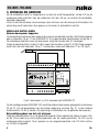
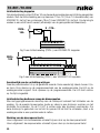
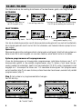
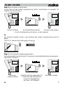
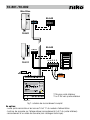
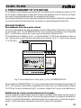
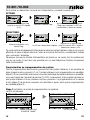
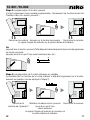
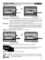
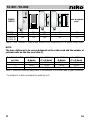
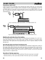
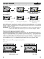
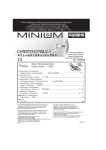
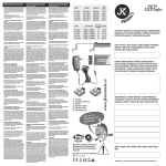
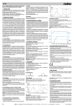
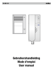
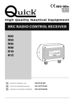
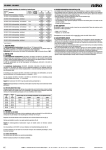
10-801 /10-802
Lees de volledige handleiding vóór installatie en ingebruikname.
1. Beschrijving
De voedingsmodules kunnen een audiodeurcommunicatiesysteem voeden en programmeren.
Bij een groot systeem of een systeem met een buitenpost met een LCD-scherm en/of video
is een bijkomende gelijkspanningsvoeding vereist.
Beide voedingsmodules zijn ontworpen voor montage in een DIN-rail kast. De maximale
configuratie van een audiosysteem wordt in tabel 1 weergegeven.
De voedingsmodules werken op de standaardnetspanning (230V~, 50Hz) en leveren gelijkspanning
voor het systeem. Naast het aansluiten van de binnen- en buitenposten op deze voedingsmodules
is het ook mogelijk een deuropener en/of een lichtpunt aan te sturen via de voedingsmodule. U
kan de tijd voor de aansturing van de deuropener en de verlichting instellen.
2. Montage
De voedingsmodules zijn geschikt voor montage in een DIN-rail kast. U sluit de voedingsmodules
aan door de netvoeding op klemmen 1 en 3 van de voedingsmodule aan te sluiten. Voor de
aansluiting van de binnen- en buitenpost(en) op de voedingsmodule, fig.1.
Volgende kabels kunnen voor de aansluiting van de binnen- en buitenpost(en) gebruikt
worden: JYSTY(-F2) 3 x 2 x 0,8mm of TPVF 3 x 2 x 0,6mm (beperkt de omvang van het
systeem, zie tabel 2.).
Niet alle paren worden in een systeem zonder video gebruikt. Toch raden wij aan om steeds
3 paren te voorzien om latere uitbreiding naar een videosysteem mogelijk te maken.
VOEDING 20 (10-801)
Als u slechts over één of twee buitenposten beschikt, kan u kiezen tussen een 2-draads
of 3-draads bedrading. Bij een 2-draads audiosysteem (fig.1) hoeft u enkel nog de P-klem
intern (in de buitenpost) met de a-klem te verbinden, zodat de naamplaat verlicht wordt. Bij
een 3-draads aansluiting (fig.1) wordt de P-ader via de voeding met de buitenpost vebonden.
Bijgevolg hoeven de klemmen P en a NIET meer intern doorverbonden te worden! Voor de
binnenposten volstaat een 2-draads bedrading.
Een deuropener (optioneel) dient op klemmen 16 en 17 van de voedingsmodule (VOEDING
20) aangesloten te worden.
VOEDING 100 (10-802)
Deze voeding wordt enkel gebruikt voor grote systemen. Een 3-draads bedrading naar de
buitenpost is vereist. Naar de binnenposten kan nog steeds met 2 aders gewerkt worden (fig.
2). De voeding van de binnen- en buitenposten wordt over 3 bussen verdeeld.
De deuropener (optioneel) sluit u aan op klemmen 20 en 21 van de voedingsmodule
(VOEDING 100).
NL
1
10-801 /10-802
Max. #
buitenposten*
voeding
10-801
10-802
10-802 &
10-805-01
20
80
17
60
20
80
5
7
2
5
180
120
180
60
>5
Tabel 1: max. aantal configuraties met de audiovoedingen
LET OP: De maximum af te leggen afstanden hangen af van de gebruikte kabel
en van het aantal buitenposten op de lijn (zie tabel 2).
# buitenposten* max. afstand max. afstand max. afstand max. afstand
per lijn
(0,6mm)
(2 x 0,6mm)
(0,8mm)
(2 x 0,8mm)
1
150m
300m
250m
500m
2
80m
150m
150m
300m
>2
beter een nieuwe lijn (bus: a en b) trekken in ster!
Tabel 2: max. afstanden afhankelijk van de diameter van de gebruikte kabel (kopergeleider)
* Ook een uitbreiding wordt als een buitenpost beschouwd!
2
NL
10-801 /10-802
Max.20ex.
05-540
ABEP
12V 1A max
10-501
05-540
ABEP
12V 1A max
a b R S P
10-511
10-173
141516171819202122232425
Relais
10-835
2-draads naar binnenpost
2- of 3-draads naar buitenpost
1
2
3
4
5
6
7
8
9 10111213
230V ~
fig.1: compleet aansluitschema
Optioneel:
-deuropener op de klemmen 16 en 17 van de voedingsmodule
-beldrukknoppen op de verdieping zelf (verbindingen E en P van de binnenpost)
-aansluiten van een belrelais (zie technische catalogus).
NL
3
10-801 /10-802
3. Werking en gebruik
Als de installatie correct is uitgevoerd en op het net wordt aangesloten, zal de LED op de
voedingsmodule oplichten. Aan de buitenpost licht de LED op, en verlicht de vandaalbestendige naamplaat.
U kan nu met de bezoeker communiceren door de hoorn van de binnenpost af te haken. De
verbinding wordt verbroken door gewoon in te haken of automatisch na 60s.
MOGELIJKE INSTELLINGEN
Externe deuropener koppelen
Op de voedingsmodule kan een externe deuropener aangesloten worden. Sluit de deuropener
aan op klemmen 16 en 17 van VOEDING 20. Er is geen andere transformator nodig (fig.1).
De inwendige weerstand van de deuropener mag niet minder dan 6Ω bedragen.
Indien de weerstand toch onder 6Ω zakt, is een transformator nodig (10-819)! De deuropener
wordt dan niet met klemmen 16 en 17 verbonden, maar met klemmen 17 en 18 (fig.2).
14 15 16 17 18 19 20 21 22 23 24 25
10-819
16 VA
1,34A
12V
8V 2A
SEC
PRI
PTC
230-240 V
50- 60 Hz
ta 45/E IP20
EN 61558-2-8
1
2
3
4
5
6
7
8
9 10 11 12 13
Fig.2: deuropener (≤ 6Ω) koppelen aan VOEDING 20
Op de voedingsmodule VOEDING 100 wordt de externe deuropener gekoppeld op klemmen
20 en 21. Om de deuropener van de nodige voeding te voorzien (fig. 2), is een externe
transformator (10-819) vereist. (De spanning is afhankelijk van de gekozen deuropener.)
Bekrachtigingsduur van het slot wijzigen
Draai de potentiometer tot op de gewenste waarde. Deze waarde ligt steeds tussen 0,8s.
en 8s. Druk daarna op de programmeertoets van de voedingsmodule. De LED op de
voedingsmodule knippert. Druk opnieuw op de programmeertoets. De LED licht continu
op. De tijd is ingesteld.
4
NL
10-801 /10-802
Lichtschakeling koppelen
Op het potentiaalvrij contact (24V en 1A) van de voedingsmodules kan een lichtkring aangesloten
worden. Sluit de lichtschakeling aan op klemmen 14 en 18 (15 en 16 doorverbinden) van
VOEDING 20, zie fig.3 en op klemmen 18 en 19 van VOEDING 100, zie fig.4. Om de kring te
voeden is een extra transfo vereist (afhankelijk van de gekoppelde last/weerstand).
8 - 12V~
230V~
10A
14 15 16 17 18 19 20 21 22 23 24 25
Fig.3: een lichtschakeling (230V~) aan VOEDING 20 koppelen
230V~
10A
8 - 12V~
18 19 20 21 22 23 24 25 26 27 28 29 30 31 32 33 34 35
1
2
3
4
5
6
7
8
9 10 11 12 13
10-819
16 VA
1,34A
12V
8V 2A
Fig.4: een lichtschakeling (230V~) aan VOEDING 100 koppelen
SEC
1
3
PRI
PTC
230-240 V
50- 60 Hz
Aanstuurtijd van de verlichting wijzigen
Draai de potentiometer tot op de gewenste waarde. Deze waarde ligt steeds tussen 0,5s.
en 5min. Druk daarna op1 de
van
2 3 programmeertoets
4 5 6 7 8 9
10 11 12 13 14
15 16de
17 voedingsmodule. De LED op de
voedingsmodule knippert. Druk opnieuw op de programmeertoets. De LED licht continu
op. De tijd is ingesteld.
ta 45/E IP20
EN 61558-2-8
Lichtschakeling bedienen vanop de binnenposten
Elke niet-geprogrammeerde drukknop aan de buitenpost schakelt het lichtrelais van de
voeding. Op de meeste binnenposten (audio en video) is een drukknop voorzien om het
lichtrelais te schakelen. Op de 10-501 is echter maar één drukknop voorhanden. Om
deze drukknop te gebruiken om het slot te openen EN het licht te schakelen, dient u de
voedingsmodule in een speciale mode te zetten.
Werking van de deuropenertoets:
Hoorn ingehaakt: lichtschakelrelais schakelt bij een druk op de deuropenertoets!
Hoorn afgehaakt: deuropenerrelais schakelt bij een druk op de deuropenertoets!
NL
5
10-801 /10-802
Om deze mode op de voeding te activeren of te deactiveren, gaat u als volgt te werk:
ACTIVEREN
14 15 16 17 18 19 20 21 22 23 24 25
14 15 16 17 18 19 20 21 22 23 24 25
1
14 15 16 17 18 19 20 21 22 23 24 25
➧
Druk op de Prog. toets tot
de LED knippert (±3s).
2
3
4
5
6
7
8
9 10 11 12 13
➧
Druk kort op de Prog. toets ter bevestiging.
De LED op de voeding licht continu op.
Laat de Prog. toets los.
1
14 15 16 17 18 19 20 21 22 23 24 25
2
3
4
5
6
7
8
9 10 11 12 13
1
14 15 16 17 18 19 20 21 22 23 24 25
DEACTIVEREN:
➧
2
3
4
5
6
7
8
9 10 11 12 13
3
4
5
6
7
8
9 10 11 12 13
➧
Druk kort op de Prog. toets. De LED op de voeding knippert.
1
2
14 15 16 17 18 19 20 21 22 23 24 25
1
2
3
4
5
6
7
8
9 10 11 12 13
Druk op de Prog. toets tot de LED
terug continu oplicht (±3s).
1
2
3
4
5
6
7
8
9 10 11 12 13
Ook bij de videobinnenposten wordt deze speciale mode gebruikt om met de functietoets,
die normaal gebruikt wordt om het licht te schakelen, een tweede interne oproep te kunnen maken.
Opmerking:
Wanneer de gebruikte voedingsmodule in deze mode wordt gezet, staat het hele systeem in
deze mode. Het is niet mogelijk om voor één telefoon enkel deze functie in te stellen.
Systeem programmeren of herprogrammeren
U kan de drukknoppen en binnenposten programmeren zodat elke drukknop aan 1 of 2
binnenposten gelinkt is (zie parallel programmeren, stap 2). Indien u toch meer binnenposten parallel wil schakelen, heeft u het servicetoestel (10-870) nodig. Omgekeerd is het
mogelijk om 1 binnenpost te linken aan 1 of meerdere drukknoppen. Het programmeren
en het resetten (stap 2) van een drukknop staan hieronder beschreven, evenals het parallel
programmeren (stap 3).
Stap 1: het systeem in programmeerstatus brengen
De LED licht op.
18 19 20 21 22 23 24 25 26 27 28 29 30 31 32 33 34 35
1
3
1 2 3 4 5 6 7 8 9
6
18 19 20 21 22 23 24 25 26 27 28 29 30 31 32 33 34 35
1
10 11 12 13 14 15 16 17
Kort drukken op
de “mode”-toets
3
1 2 3 4 5 6 7 8 9
10 11 12 13 14 15 16 17
De LED knippert.
NL
10-801 /10-802
Stap 2: een drukknop programmeren
(enkel indien het een nieuwe programmering betreft. Overschrijven is onmogelijk. Zie
‘resetten van een drukknop’).
De hoorn afhaken
Op de beldrukknop drukken. De hoorn terug inhaken
U hoort het belsignaal aan de binnen- en de buitenpost.
Of:
een drukknop resetten (indien u een drukknop een andere programmering wenst te
geven).
Druk tot u 2 keer een biep heeft gehoord (ong.6s.).
1
2
6s
Stap 3: 2 binnenposten parallel programmeren.
(Het systeem gaat ervan uit dat reeds 1 binnenpost op de betreffende drukknop geprogrammeerd werd, zie stap 2)
Hoorn van
toestel 2 afhaken
NL
Dezelfde drukknop ingedrukken tot u 3 keer een biep heeft gehoord. U hoort het belsignaal aan
de binnen- en buitenpost.
Hoorn terug inhaken
7
10-801 /10-802
Stap 4: de programmeerstatus beëindigen.
18 19 20 21 22 23 24 25 26 27 28 29 30 31 32 33 34 35
1
18 19 20 21 22 23 24 25 26 27 28 29 30 31 32 33 34 35
3
1
1 2 3 4 5 6 7 8 9
10 11 12 13 14 15 16 17
3
1 2 3 4 5 6 7 8 9
10 11 12 13 14 15 16 17
Kort drukken op
De LED licht
de “mode”-toets
continu op.
LET OP:Bij het parallel programmeren van meerdere binnenposten (max. 2 op de voedingsmodule of meerdere met het servicetoestel) is er een groter stroomverbruik.
De aantallen opgegeven in tabel 1 gelden dan NIET meer.
Opmerking: Indien u geen toegang heeft tot de woning en u dus de hoorn van de binnenpost niet kan afhaken, kan u de programmering via het sevicetoestel
(10-870) uitvoeren, zie handleiding. Indien een beldrukknop aan de voordeur
voorzien is, kan u de programmering ook als volgt uitvoeren:
Stap 1: systeem in programmeerstatus brengen
LED licht continu op.
18 19 20 21 22 23 24 25 26 27 28 29 30 31 32 33 34 35
1
18 19 20 21 22 23 24 25 26 27 28 29 30 31 32 33 34 35
3
1
1 2 3 4 5 6 7 8 9
10 11 12 13 14 15 16 17
3
1 2 3 4 5 6 7 8 9
Kort drukken op
de “mode”-toets
Stap 2: beldrukknop aan de juiste binnenpost linken
10 11 12 13 14 15 16 17
De LED knippert.
Druk op de beldrukknop die bij de deur staat, los die en druk er
nogmaals op (binnen 3s).
12V 1A max
12V 1A max
12V 1A max
Stap 3: beldrukknop programmeren
1
2
6s
Kort drukken op de gewenste beldrukknop aan de voordeur. U hoort het
belsignaal aan de binnen- en buitenpost ter bevestiging.
8
NL
10-801 /10-802
Stap 4: programmeerstatus beëindigen.
18 19 20 21 22 23 24 25 26 27 28 29 30 31 32 33 34 35
1
3
1 2 3 4 5 6 7 8 9
18 19 20 21 22 23 24 25 26 27 28 29 30 31 32 33 34 35
1
10 11 12 13 14 15 16 17
3
1 2 3 4 5 6 7 8 9
Kort drukken op
de “mode”-toets
10 11 12 13 14 15 16 17
De LED licht
continu op.
4. TECHNISCHE GEGEVENS
VOEDING 20 (10-801):
Afmetingen:.........................4E breed (h90 x b72 x d70mm)
Ingang:................................230V, 50Hz
Uitgang (bus):......................24V, 50mA (a en b)
Extra voeding:......................P-ader (24V DC)
Deurslot koppelbaar:............8-12V~
Potentiaalvrij contact:...........24V DC en 1A
VOEDING 100 (10-802):
Afmetingen:.........................6TE breed (h90 x b105 x d70mm)
Ingang:................................230V, 50Hz
Uitgang (bus):......................3 x 24V, 60mA (a en b)
Extra voeding:......................P-ader (24V DC)
Deurslot koppelbaar:............24V DC en 1A
Potentiaalvrij contact:...........24V DC en 1A
5. WETTELIJKE WAARSCHUWINGEN
-De installatie dient te worden uitgevoerd door een bevoegd persoon en met inachtname
van de geldende voorschriften.
-Deze handleiding dient aan de gebruiker te worden overhandigd. Zij moet bij het dossier
van de elektrische installatie worden gevoegd en dient te worden overgedragen aan
eventuele nieuwe eigenaars. Bijkomende exemplaren zijn verkrijgbaar via de Niko-website
of -supportdienst.
-Bij de installatie dient rekening gehouden te worden met (lijst is niet limitatief):
-de geldende wetten, normen en reglementen;
-de stand van de techniek op het ogenblik van de installatie;
-het feit dat een handleiding alleen algemene bepalingen vermeldt en dient gelezen te
worden binnen het kader van elke specifieke installatie;
-de regels van goed vakmanschap.
NL
9
10-801 /10-802
-Bij twijfel kan u de supportdienst van Niko raadplegen of contact opnemen met een
erkend controleorganisme.
Support België: Support Nederland:
tel. + 32 3 778 90 80
tel. + 31 183 64 06 60
website: http://www.niko.be
website: http://www.niko.nl
e-mail: [email protected] e-mail: [email protected]
In geval van defect kan u uw product terugbezorgen aan een erkende Niko-groothandel
samen met een duidelijke omschrijving van uw klacht (manier van gebruik, vastgestelde
afwijking…).
6. GARANTIEBEPALINGEN
-Garantietermijn: twee jaar vanaf leveringsdatum. Als leveringsdatum geldt de factuurdatum
van aankoop van het goed door de consument. Indien geen factuur voorhanden is, geldt
de productiedatum.
-De consument is verplicht Niko schriftelijk over het gebrek aan overeenstemming te
informeren, uiterlijk binnen de twee maanden na vaststelling.
-In geval van een gebrek aan overeenstemming van het goed heeft de consument recht
op een kosteloze herstelling of vervanging, wat door Niko bepaald wordt.
-Niko is niet verantwoordelijk voor een gebrek of schade als gevolg van een foutieve
installatie, oneigenlijk of onachtzaam gebruik of verkeerde bediening of transformatie
van het goed.
-De dwingende bepalingen van de nationale wetgevingen betreffende de verkoop van
consumptiegoederen en de bescherming van de consumenten van de landen waarin Niko
rechtstreeks of via zuster/dochtervennootschappen, filialen, distributeurs, agenten of
vaste vertegenwoordigers verkoopt, hebben voorrang op bovenstaande bepalingen.
10
NL
10-801 /10-802
Lisez entièrement le mode d’emploi avant toute installation et mise en service.
1. Description
Les modules d’alimentation permettent d’alimenter et de programmer un système de
communication de porte audio. Une alimentation en tension continue est nécessaire dans
le cas d’un grand système ou d’un système équipé d’un poste extérieur avec écran LCD
et/ou vidéo.
Les deux modules d’alimentation sont destinés à une installation dans une armoire à rail
DIN. La configuration maximale d’un système audio est indiquée dans tableau 1.
Les modules d’alimentation fonctionnent sur la tension de réseau standard (230V~, 50Hz)
et fournissent une tension continue au système. Outre le raccordement des postes intérieurs
et extérieurs à ces modules d’alimentation, il est également possible de commander un
ouvre-porte et/ou une lampe via le module d’alimentation. Les temps pour la commande
de l’ouvre-porte et de l’éclairage sont tous deux paramétrables.
2. Montage
Les modules d’alimentation conviennent à une installation dans une armoire à rail DIN.
Raccordez les modules d’alimentation des bornes 1 et 3 au réseau. Pour le schéma de
raccordement des postes intérieurs et extérieurs au module d’alimentation, voir fig.1.
Types de câbles possibles pour le raccordement des postes intérieurs et extérieurs: JYSTY
(-F2) 3 x 2 x 0,8mm ou TPVF 3 x 2 x 0,6mm (Ce dernier câble limite toutefois quelque peu
la taille du système, voir tableau 2.).
Toutes les paires ne sont pas utilisées dans un système sans vidéo, mais nous conseillons de
prévoir quand même toujours 3 paires pour permettre l’extension vers un système vidéo!
ALIMENTATION 20 (10-801)
Si vous disposez seulement d’un ou de deux postes extérieurs, vous avez le choix entre un
raccordement à 2 fils et à 3 fils. Dans le cas d’un système audio à 2 fils (fig. 1), vous devez
uniquement raccorder le conducteur P en interne (dans le poste extérieur) au conducteur a,
de manière à ce que le porte-étiquette soit éclairé. Dans le cas d’un système audio à 3 fils
(fig. 1), le conducteur P de l’alimentation est raccordé au poste extérieur. Par conséquent,
les conducteurs P et a NE DOIVENT PLUS être raccordés en interne! Un raccordement à 2
fils suffit pour les postes intérieurs!
Un ouvre-porte (en option) doit être raccordé sur les bornes 16 et 17 du module d’alimentation (ALIMENTATION 20).
ALIMENTATION 100 (10-802)
Cette alimentation est uniquement utilisée pour de grands systèmes. Un câble à 3 fils vers
le poste extérieur est donc nécessaire! On peut toujours travailler avec 2 fils vers les postes
intérieurs (fig. 2). L’alimentation des postes intérieurs et extérieurs s’effectue par 3 bus.
L’ouvre-porte (option) se raccorde aux bornes 20 et 21 du module d’alimentation (ALIMENTATION 100).
FR
11
10-801 /10-802
alimentation
Max. #
postes
extérieurs*
10-801
20
17
20
5
2
10-802
80
60
80
7
5
10-802 &
180
120
180
60
>5
10-805-01
Tableau 1: nombres max. de configurations avec les alimentations audio
ATTENTION:
Les distances max. pouvant être parcourues dépendent du câble utilisé et du
nombre de postes extérieurs sur la ligne (voir tableau 2).
# postes extér.* distance max. distance max. distance max. distance max.
par ligne
(0,6mm)
(2 x 0,6mm)
(0,8mm)
(2 x 0,8mm)
1
150m
300m
250m
500m
2
80m
150m
150m
300m
>2
préférable de tirer une nouvelle ligne (bus: a et b) en étoile.
Tableau 2: distances maximales, en fonction de la section du câble utilisé (conducteur
en cuivre).
* Une extension est également considérée comme un poste extérieur!
12
FR
10-801 /10-802
Max.20ex.
05-540
ABEP
12V 1A max
10-501
05-540
ABEP
12V 1A max
a b R S P
10-511
10-173
141516171819202122232425
1
2
3
4
5
6
7
8
9 10111213
Relais
10-835
2 fils vers poste intérieur
2 ou 3 fils vers poste extérieur
230V ~
fig.1: schéma de raccordement complet
En option:
-ouvre-porte raccordé sur les bornes 16 et 17 du module d’alimentation
-boutons de sonnerie sur l’étage même (raccordements E et P du poste intérieur)
-raccordement d’un relais de sonnerie (voir catalogue technique).
10-801 /10-802
3. Fonctionnement et utilisation
Si l’installation a été réalisée correctement et l’installation est connectée au réseau, la LED
sur le module d’alimentation s’illuminera. Sur le poste extérieur la LED s’illumine, de façon
à ce que le porte-étiquette résistant au vandalisme soit éclairé.
Vous pouvez maintenant communiquer avec le visiteur en décrochant le combiné du poste intérieur.
La communication est interrompue en raccrochant ou automatiquement après 60s.
REGLAGES POSSIBLES
Raccordement d’un ouvre-porte externe
Un ouvre-porte externe peut être raccordé au module d’alimentation. Raccordez l’ouvre-porte
sur les bornes 16 et 17 d’ALIMENTATION 20. Aucun autre transformateur n’est nécessaire
(fig.1). La résistance interne de l’ouvre-porte ne peut être inférieure à 6Ω.
Si la résistance est inférieure à 6Ω, un transformateur (10-819) est nécessaire. Dans ce
cas, l’ouvre porte ne doît pas être raccordé sur les bornes 16 et 17, mais sur les bornes
17 et 18 (fig.2).
14 15 16 17 18 19 20 21 22 23 24 25
10-819
16 VA
1,34A
12V
8V 2A
SEC
PRI
PTC
230-240 V
50- 60 Hz
ta 45/E IP20
EN 61558-2-8
1
2
3
4
5
6
7
8
9 10 11 12 13
Fig.2: raccordement de l’ouvre-porte (≤ 6Ω) à ALIMENTATION 20
Sur le module d’ALIMENTATION 100, l’ouvre-porte externe est raccordé entre les bornes 20
et 21. Pour assurer l’alimentation nécessaire de l’ouvre-porte, un transformateur externe
(10-819) est toujours nécessaire (fig.2). (La tension dépend de l’ouvre-porte sélectionné.)
Modification de la durée de fonctionnement de la gâche
Tournez d’abord le potentiomètre jusqu’à la valeur souhaitée. Cette valeur se situe toujours
entre 0,8 et 8s. Appuyez ensuite sur la touche de programmation du module d’alimentation.
La LED du module d’alimentation clignote. Appuyez de nouveau sur la touche de programmation, la LED reste alors allumée en continue. Le temps est paramétré.
14
FR
10-801 /10-802
Raccordement d’une commande d’éclairage
Sur le contact libre de potentiel (24V et 1A) des modules d’alimentation, il est possible de
raccorder un circuit d’éclairage. Raccordez la commande d’éclairage sur les bornes 14 et
18 d’ALIMENTATION 20 (raccordez les bornes 15 et 16), voir fig.3 et sur les bornes 18 et 19
d’ALIMENTATION 100, voir fig.4. Pour alimenter le circuit, un transformateur supplémentaire
est nécessaire (en fonction de la charge/résistance connectée).
8 - 12V~
230V~
10A
14 15 16 17 18 19 20 21 22 23 24 25
Fig.3: raccordement d’une commande d’éclairage (230V~) à ALIMENTATION 20
230V~
10A
8 - 12V~
18 19 20 21 22 23 24 25 26 27 28 29 30 31 32 33 34 35
1
2
3
4
5
6
7
8
9 10 11 12 13
Fig.4: raccordement d’une commande d’éclairage (230V~) à ALIMENTATION 100
10-819
16 VA
1,34A
12V
8V 2A
Modification du temps de commande de l’éclairage
Tournez le potentiomètre jusqu’à la valeur souhaitée. Cette valeur se situe toujours entre
0,5s et 5min. Appuyez ensuite sur la touche de programmation du module d’alimentation.
La LED du module d’alimentation commence à clignoter. Appuyez de nouveau sur la touche
3 4 5 alors
6 7 8 allumée
9
10 11 12en
13 14continue.
15 16 17
de programmation. La LED1 2reste
Le temps est paramétré.
SEC
1
3
PRI
PTC
230-240 V
50- 60 Hz
ta 45/E IP20
EN 61558-2-8
Commande de l’éclairage depuis les postes intérieurs
Chaque bouton-poussoir non programmé du poste extérieur commute le relais d’éclairage
de l’alimentation. Sur la plupart des postes intérieurs (audio et vidéo), un bouton-poussoir
est prévu pour commuter le relais d’éclairage. 10-501 ne dispose toutefois que d’un seul
bouton-poussoir. Pour pouvoir utiliser ce bouton-poussoir pour ouvrir la gâche ET commuter
l’éclairage, vous placez le module d’alimentation sur un mode spécial.
Fonctionnement de la touche de l’ouvre-porte:
Combiné raccroché: le relais d’éclairage s’enclenche lorsque vous appuyez sur la touche
de l’ouvre-porte!
Combiné décroché: le relais d’ouvre-porte s’enclenche lorsque vous appuyez sur la
touche de l’ouvre-porte!
FR
15
10-801 /10-802
Pour activer ou désactiver ce mode sur l’alimentation, procédez comme suit:
ACTIVER:
14 15 16 17 18 19 20 21 22 23 24 25
14 15 16 17 18 19 20 21 22 23 24 25
➧
Appuyez sur la touche Prog.
jusqu’à ce que la LED clignote
(±3s).
1
14 15 16 17 18 19 20 21 22 23 24 25
2
3
4
5
6
7
8
➧
Relâchez la touche Prog.
9 10 11 12 13
1
14 15 16 17 18 19 20 21 22 23 24 25
2
3
4
5
6
7
8
9 10 11 12 13
Appuyez brièvement sur la touche
Prog. pour confirmer. La LED de
l’alimentation s’allume en continu.
1
14 15 16 17 18 19 20 21 22 23 24 25
2
3
4
5
6
7
8
9 10 11 12 13
14 15 16 17 18 19 20 21 22 23 24 25
DESACTIVER:
➧
1
Appuyez brièvement sur la
touche Prog.
2
3
4
5
6
7
8
9 10 11 12 13
➧
Appuyez sur la touche Prog.
La LED de l’alimentation clignote. jusqu’à ce que la LED s’allume à
nouveau en continu (±3s).
1
2
3
4
5
6
7
8
9 10 11 12 13
1
2
3
4
5
6
7
8
9 10 11 12 13
Ce mode spécial est également utilisé avec la série les postes intérieurs video pour pouvoir
effectuer un second appel interne à l’aide de la touche de fonction, normalement utilisée
pour commuter l’éclairage.
Remarque: lorsque le module d’alimentation est placé sur ce mode, tout le système est
mis sur ce mode. Il n’est donc pas possible pour un seul téléphone d’activer uniquement
cette fonctionnalité!
Programmation ou reprogrammation du système
Pour la programmation des boutons-poussoirs et des postes intérieurs, il est possible de
relier chaque bouton-poussoir à 1 ou 2 postes intérieurs (voir programmation en parallèle,
étape 2). Si vous souhaitez néanmoins connecter davantage de postes intérieurs en parallèle,
vous avez besoin de l’appareil de service (10-870). Inversement, il est possible de relier un
seul poste intérieur à un ou plusieurs boutons-poussoirs. La programmation et la remise
à zéro (étape 2) de boutons-poussoirs sont décrites ci-après, ainsi que la programmation
en parallèle (étape 3).
Etape 1: activation du mode de programmation du système
La LED est allumée.
18 19 20 21 22 23 24 25 26 27 28 29 30 31 32 33 34 35
1
3
1 2 3 4 5 6 7 8 9
16
18 19 20 21 22 23 24 25 26 27 28 29 30 31 32 33 34 35
1
Brève pression sur
la touche “mode”
10 11 12 13 14 15 16 17
3
1 2 3 4 5 6 7 8 9
La LED clignote.
10 11 12 13 14 15 16 17
FR
10-801 /10-802
Etape 2: programmation du bouton-poussoir
(Il s’agit uniquement d’une nouvelle programmation, l’écrasement ne fonctionne pas! Voir
‘Remise à zéro d’un bouton-poussoir’).
Décrocher le combiné Appuyer sur le bouton de sonnerie. Raccrocher le combiné
Le signal d’appel est entendu sur le poste intérieur et extérieur!
Ou:
remise à zéro du bouton-poussoir (Cette étape est nécessaire avant de pouvoir reprogrammer
un bouton-poussoir).
Appuyer jusqu’à ce que 2 bips soient entendus (env. 6s.).
1
2
6s
Etape 3: programmation de 2 postes intérieurs en parallèle.
(Le système part du principe qu’un poste intérieur a déjà été programmé sur le boutonpoussoir en question comme expliqué à l’étape 2)
Décrocher le
Maintenir le même bouton-poussoir Raccrocher le combiné
combiné de l’appareil 2
jusqu’à ce que 3 bips
soient entendus.
Le signal d’appel est entendu de nouveau sur
le poste intérieur et extérieur.
FR
17
10-801 /10-802
Etape 4: arrêt du mode programmation.
18 19 20 21 22 23 24 25 26 27 28 29 30 31 32 33 34 35
1
18 19 20 21 22 23 24 25 26 27 28 29 30 31 32 33 34 35
3
1
1 2 3 4 5 6 7 8 9
10 11 12 13 14 15 16 17
3
1 2 3 4 5 6 7 8 9
10 11 12 13 14 15 16 17
Appuyer brièvement
La LED est allumée
sur la touche “mode”
en continu.
ATTENTION: en cas de programmation en parallèle de plusieurs postes intérieurs (max.
2 sur le module d’alimentation ou plus avec l’appareil de service), vous
devez tenir compte d’une consommation de courant supérieure. Les chiffres
indiqués dans le tableau 1 ne sont alors PLUS valables!
Remarque: si vous n’avez pas accès au logement et que vous ne pouvez donc pas
décrocher le combiné du poste intérieur, vous pouvez effectuer la programmation via l’appareil de service (référence: 10-870, voir mode d’emploi). Si
un bouton de sonnerie est installé sur la porte d’entrée, vous pouvez effectuer
la programmation comme suit:
Etape 1: activation du mode de programmation du système
La LED est allumée en continu.
18 19 20 21 22 23 24 25 26 27 28 29 30 31 32 33 34 35
1
18 19 20 21 22 23 24 25 26 27 28 29 30 31 32 33 34 35
3
1
1 2 3 4 5 6 7 8 9
10 11 12 13 14 15 16 17
3
1 2 3 4 5 6 7 8 9
10 11 12 13 14 15 16 17
Appuyer brièvement
La LED clignote.
sur la touche “mode”
Etape 2: raccordement du bouton de sonnerie au poste intérieur adéquat
Dans les 3s. appuyez sur le bouton de sonnerie se trouvant sur
la porte, relâchez-le et appuyez de nouveau dessus.
12V 1A max
12V 1A max
12V 1A max
Etape 3: programmation du bouton de sonnerie
1
2
6s
18
Appuyer brièvement sur le bouton de sonnerie souhaité sur la porte d’entrée. Un signal retentira tant sur le poste intérieur que le poste extérieur
en guise de confirmation.
FR
10-801 /10-802
Etape 4: arrêt du mode de programmation
18 19 20 21 22 23 24 25 26 27 28 29 30 31 32 33 34 35
1
3
1
1 2 3 4 5 6 7 8 9
18 19 20 21 22 23 24 25 26 27 28 29 30 31 32 33 34 35
10 11 12 13 14 15 16 17
3
1 2 3 4 5 6 7 8 9
Appuyer brièvement
sur la touche “mode”
10 11 12 13 14 15 16 17
La LED est allumée
en continu.
4. Caracteristiques techniques
ALIMENTATION 20 (10-801):
Dimensions:..................................4U de large (h90 x l72 x p70mm)
Entrée:.........................................230V~, 50Hz
Sortie (bus)::.................................24V, 50mA (a et b)
Alimentation supplémentaire:.........conducteur P (24V DC)
Gâche de porte connectable:.........8-12V~
Contact libre de potentiel:..............24V DC et 1A
ALIMENTATION 100 (10-802):
Dimensions:..................................6U de large (h90 x l105 x p70mm)
Entrée:.........................................230V~, 50Hz
Sortie (bus):..................................3 x 24V, 60mA (a et b)
Alimentation supplémentaire:.........conducteur P (24V DC)
Gâche de porte connectable:.........24V DC et 1A
Contact libre de potentiel:..............24V DC et 1A
5. PRESCRIPTIONS LEGALES
-L’installation doit être effectuée par une personne compétente et dans le respect des
prescriptions en vigueur.
-Ce mode d’emploi doit être remis à l’utilisateur. Il doit être joint au dossier de l’installation électrique et être remis à d’éventuels autres propriétaires. Des exemplaires
supplémentaires peuvent être obtenus sur le site web ou auprès du service ‘support
Niko’.
-Il y a lieu de tenir compte des points suivants avant l’installation (liste non limitative):
-les lois, normes et réglementations en vigueur;
-l’état de la technique au moment de l’installation;
-ce mode d’emploi qui doit être lu dans le cadre de toute installation spécifique;
-les règles de l’art.
-En cas de doute, vous pouvez appeler le service ‘support Niko’ ou vous adresser à un
organisme de contrôle reconnu.
FR
19
10-801 /10-802
Support Belgique: Support France:
+ 32 3 778 90 80
+ 33 820 20 6625
site web: http://www.niko.be
site web: http://www.niko.fr
e-mail: [email protected]
e-mail: [email protected]
En cas de défaut de votre appareil, vous pouvez le retourner à un grossiste Niko agréé,
accompagné d’une description détaillée de votre plainte (manière d’utilisation, divergence
constatée…).
6. CONDITIONS DE GARANTIE
-Délai de garantie: 2 ans à partir de la date de livraison. La date de la facture d’achat
par le consommateur fait office de date de livraison. Sans facture disponible, la date
de fabrication est seule valable.
-Le consommateur est tenu de prévenir Niko par écrit de tout manquement à la concordance
des produits dans un délai max. de 2 mois après constatation.
-Au cas ou pareil manquement serait constaté, le consommateur a droit à une réparation
gratuite ou à un remplacement gratuit selon l’avis de Niko.
-Niko ne peut être tenu pour responsable pour un défaut ou des dégâts suite à une
installation fautive, à une utilisation contraire ou inadaptée ou à une transformation du
produit.
-Les dispositions contraignantes des législations nationales ayant trait à la vente de
biens de consommation et la protection des consommateurs des différents pays où
Niko procède à la vente directe ou par entreprises interposées, filiales, distributeurs,
agents ou représentants fixes, prévalent sur les dispositions susmentionnées.
20
FR
10-801 /10-802
Read the complete manual before attempting installation and activating the
system.
1. Description
The power supply modules can be used to power and programme an audio door communication system. For large systems or systems using an external unit with LCD display
and/or video, a supplementary DC voltage power supply is needed.
Both power supply modules are designed for DIN-rail mounting. The maximum configuration
of an audio system is given in table 1.
The power supply modules operate at the standard mains voltage (230V~, 50Hz) and supply the system with DC voltage. These power supply modules not only allow connection of
the internal and external units but can also be used to control a door opener and/or a light
source. The activation times of the door opener and the lighting can both be set.
2. Installation
The power supply modules are suitable for DIN-rail cabinet mounting. You can connect the
power supply modules by connecting the mains supply to terminals 1 and 3 of the power
supply module. For the connection of the internal and external unit to the power supply
module, see fig.1.
Following cables can be used for connecting the internal and external unit(s): JYSTY(-F2) 3 x 2
x 0,8mm or TPVF 3 x 2 x 0,6mm (to some extent limits the size of the system, see table 2.).
Not all pairs are used in a system without video. Yet we do recommend to always provide
3 pairs in order to allow future extension to a video system.
POWER SUPPLY 20 (10-801)
If you only have 1 or 2 external units, you can choose between 2- or 3-wire wiring. In a 2-wire
audio system (fig.1), you only need to jumper the P terminal (in the external unit) and the
a terminal for the nameplate to be illuminated. In case of a 3-wire connection (fig.1), the P
wire is connected to the external unit via the power supply. Therefore, terminals P and ‘a’ no
longer need to be jumpered. For the internal units, a 2-wire connection is sufficient.
A door opener (optional) must be connected to terminals 16 and 17 of the power supply
module (POWER SUPPLY 20).
POWER SUPPLY 100 (10-802)
This power supply is only used for large systems. A 3-wire wiring to the external unit is thus
required. For wiring to the internal units, a 2-wire connection can still be used (fig. 2). The
power supply of the internal and external units is split up into 3 busses.
Connect the door opener (optional) to terminals 20 and 21 of the power supply module
(POWER SUPPLY 100).
EN
21
10-801 /10-802
POWER
SUPPLY
max. # external
units*
10-801
20
17
20
5
2
10-802
80
60
80
7
5
10-802 &
180
120
180
60
>5
10-805-01
table 1: max. number of internal and external units depending on the power supply used
NOTE:
The max. distances to be covered depend on the cable used and the number of
external units on the line (see table 2).
# external units* max. distance max. distance max. distance max. distance
per line
(0,6mm)
(2 x 0,6mm)
(0,8mm)
(2 x 0,8mm)
1
150m
300m
250m
500m
2
80m
150m
150m
300m
>2
preferably drawing a new line (bus: a and b) in star!
Table 2: maximum distances dependent on the diameter of the cable used (copper conductor)
* An extension is also considered an external unit!
22
EN
10-801 /10-802
Max.20ex.
05-540
ABEP
12V 1A max
10-501
05-540
ABEP
12V 1A max
a b R S P
10-511
10-173
141516171819202122232425
1
2
3
4
5
6
7
8
9 10111213
Relais
10-835
2-wire to internal unit
2- or 3-wire to external unit
230V ~
fig.1: complete connection diagram
Optional:
-connection of a door opener to terminals 16 and 17 of the power supply module
-bell push-buttons on the floor itself (connections E end P of the internal unit)
-connection of a bell relay contact (see technical catalogue).
EN
23
10-801 /10-802
3. Operaton and use
If the installation has been carried out correctly and the system is connected to the mains,
the LED on the power supply module will lighten up. The LED on the external unit also
lightens up, thereby illuminating the antivandal nameplate.
You can now communicate with your visitor by picking up the receiver of the internal unit. The
communication ends automatically after 60s. or simply by putting the receiver down.
POSSIBLE SETTINGS
Connecting an external door opener
An external door opener can be connected to the power supply module. Connect the door
opener to terminals 16 and 17 of POWER SUPPLY 20. No other transformer is needed (fig.1).
The internal resistance of the door opener should not be less than 6Ω.
If the resistance drops below 6Ω, a transformer (10-819) is required. The door opener is
then not connected to terminals 16 and 17, but to terminals 17 and 18 (fig.2).
14 15 16 17 18 19 20 21 22 23 24 25
10-819
16 VA
1,34A
12V
8V 2A
SEC
PRI
PTC
230-240 V
50- 60 Hz
ta 45/E IP20
EN 61558-2-8
1
2
3
4
5
6
7
8
9 10 11 12 13
Fig.2: connecting door opener (≤ 6Ω) to POWER SUPPLY 20
On power supply module POWER SUPPLY 100, the external door opener is connected to
terminals 20 and 21. To provide the door opener with the necessary power, an external transformer (10-819) is required (fig. 2). (The voltage depends on the selected door opener.)
Modifying the excitation time of the lock
Turn the potentiometer to the desired value. This value always lies between 0,8s. and 8s.
Press the programming key on the power supply module. The LED on the power supply
module blinks. Then again press the programming key. The LED lightens steadily. The
time has been set.
24
EN
10-801 /10-802
Connecting a light circuit
A light circuit can be connected to the potential free contact (24V and 1A) of the power
supply modules. Connect the light circuit to terminals 14 and 18 (jumpering 15 and 16)
of POWER SUPPLY 20, see fig.3 and to terminals 18 and 19 of POWER SUPPLY 100, see
fig.4. An additional transformer is needed to power the circuit (depending on the connected
load/resistance).
8 - 12V~
230V~
10A
14 15 16 17 18 19 20 21 22 23 24 25
Fig.3: connecting a light circuit (230V~) to POWER SUPPLY 20
230V~
10A
8 - 12V~
18 19 20 21 22 23 24 25 26 27 28 29 30 31 32 33 34 35
1
2
3
4
5
6
7
8
9 10 11 12 13
10-819
16 VA
1,34A
12V
8V 2A
Fig.4: connecting a light circuit (230V~) to POWER SUPPLY 100
SEC
1
3
PRI
PTC
230-240 V
50- 60 Hz
Modifying the activation time of the lighting
Turn the potentiometer to the desired value. This value always lies between 0,5s. and 5 min.
Press the programming key
The LED on the power supply
1 2 on
3 4 the
5 6 7power
8 9
10supply
11 12 13 14module.
15 16 17
module blinks. Then again press the programming key. The LED lightens steadily. The time
has been set.
ta 45/E IP20
EN 61558-2-8
Operating the light circuit from the internal units
Any non-programmed push-button on the external unit switches the light relay contact of
the power supply. Most internal units (audio and video) are equipped with a push-button
for switching the light relay contact. The 10-501 however only has 1 push-button. To use
this push-button in order to open the lock AND to switch the light, you must put the power
supply module in a special mode.
Operation of the door open key:
- receiver put down: light switch relay switches if the door open key is pressed!
- receiver picked up: door open relay switches if the door open key is pressed!
EN
25
10-801 /10-802
In order to activate or deactivate this mode on the power supply, proceed as follows:
ACTIVATING:
14 15 16 17 18 19 20 21 22 23 24 25
14 15 16 17 18 19 20 21 22 23 24 25
14 15 16 17 18 19 20 21 22 23 24 25
➧
Press the Prog. key until the LED
blinks (±3s).
1
2
3
4
5
6
7
8
9 10 11 12 13
➧
Let go of the Prog. key.
1
14 15 16 17 18 19 20 21 22 23 24 25
2
3
4
5
6
7
8
9 10 11 12 13
14 15 16 17 18 19 20 21 22 23 24 25
Briefly press the Prog. key in confirmation. The LED on the power supply
continuously lights.
1
2
3
4
5
6
7
8
9 10 11 12 13
14 15 16 17 18 19 20 21 22 23 24 25
DEACTIVATING:
➧
1
2
3
4
5
6
7
8
9 10 11 12 13
Briefly press the Prog. key.
➧
The LED on the power supply
blinks.
1
2
3
4
5
6
7
8
9 10 11 12 13
Press the Prog. key until the LED
again blinks continuously (±3s).
1
2
3
4
5
6
7
8
9 10 11 12 13
Also with the video internal units, this special mode is used in order to allow the function
key, which normally is used to switch the light, to be used to set up a second internal call.
Remark:When the power supply module used is put in this mode, the entire system will
be in this mode. It is not possible to activate this functionality for 1 telephone.
Programming or reprogramming the system
You can programme the push-buttons and internal units to link each push-button to 1 or 2
internal units (see parallel programming, step 2). If you want to connect more internal units
in parallel, you will need the service unit (10-870). Conversely, you can assign 1 internal
unit to 1 or more push-buttons. Programming and resetting a push-button (step 2) and
parallel programming (step 3) are described below.
Step 1: entering system programming status
The LED lightens.
18 19 20 21 22 23 24 25 26 27 28 29 30 31 32 33 34 35
1
3
1 2 3 4 5 6 7 8 9
26
18 19 20 21 22 23 24 25 26 27 28 29 30 31 32 33 34 35
1
10 11 12 13 14 15 16 17
Briefly press the “mode” button
3
1 2 3 4 5 6 7 8 9
10 11 12 13 14 15 16 17
The LED blinks.
EN
10-801 /10-802
Step 2: programming a push-button
(With a new programming. Overwriting is not possible. See ‘Resetting a push-button’).
Pick up the receiver
Press the bell push-button. Put the receiver down
You hear the ringing signal both on the internal and external unit.
Or:
resetting a push-button (in case you want to reprogramme a push-button).
Keep pressing until you hear 2 beeps (about 6s.).
1
2
6s
Step 3: programming 2 internal units in parallel
(The system assumes that 1 internal unit has already been programmed on the relevant
push-button, see step 2)
Pick up receiver
Press the same push-button
Put receiver down again
of unit 2
until you hear 3 beeps.
You hear the ringing signal both on the internal and external unit.
EN
27
10-801 /10-802
Step 4: ending programming status
18 19 20 21 22 23 24 25 26 27 28 29 30 31 32 33 34 35
1
18 19 20 21 22 23 24 25 26 27 28 29 30 31 32 33 34 35
3
1
1 2 3 4 5 6 7 8 9
10 11 12 13 14 15 16 17
3
1 2 3 4 5 6 7 8 9
Briefly press
the “mode” button
10 11 12 13 14 15 16 17
The LED lightens steadily.
NOTE: The parallel programming of multiple internal units (max. 2 on the power supply
module or more with the service unit) will increase the power consumption. The
numbers given in table 1 will then NO LONGER apply.
Remark:If you do not have access to the premises, and thus cannot pick up the receiver of
the internal unit, you can carry out the programming via the service unit (reference:
10-870, see manual). If a bell push-button is present at the front door, you can
also carry out the programming as follows:
Step 1: entering system programming status
The LED is on.
18 19 20 21 22 23 24 25 26 27 28 29 30 31 32 33 34 35
1
18 19 20 21 22 23 24 25 26 27 28 29 30 31 32 33 34 35
3
1
1 2 3 4 5 6 7 8 9
10 11 12 13 14 15 16 17
3
1 2 3 4 5 6 7 8 9
Briefly press the “mode” button
Step 2: linking the bell push-button to the correct internal unit
10 11 12 13 14 15 16 17
The LED blinks.
Press the bell push-button at the door, release it and press it
again (within 3s
12V 1A max
12V 1A max
12V 1A max
Step 3: programming a bell push-button
1
2
6s
28
Briefly press the relevant bell push-button at the front door. You hear a
ringing signal both on the internal and external unit in confirmation of
the programming.
EN
10-801 /10-802
Step 4: ending programming status
18 19 20 21 22 23 24 25 26 27 28 29 30 31 32 33 34 35
1
3
1 2 3 4 5 6 7 8 9
18 19 20 21 22 23 24 25 26 27 28 29 30 31 32 33 34 35
1
10 11 12 13 14 15 16 17
Briefly press
the “mode” button
3
1 2 3 4 5 6 7 8 9
10 11 12 13 14 15 16 17
The LED lightens steadily.
4. TECHNICAL DATA
POWER SUPPLY 20 (10-801):
Dimensions:.........................4U wide (h90 x w72 x d70mm)
Input:..................................230V~, 50Hz
Output (bus):........................24V, 50mA (a and b)
Additional power supply:.......P-wire (24V DC)
Connectable doorlock:..........8-12V~
Potential free contact:..........24V DC and 1A
POWER SUPPLY 100 (10-802):
Dimensions:.........................6U wide (h90 x w105 x d70mm)
Input:..................................230V, 50Hz
Output (bus):........................3 x 24V, 60mA (a and b)
Additional power supply:.......P-wire (24V DC)
Connectable doorlock:..........24V DC and 1A
Potential free contact:..........24V DC and 1A
5. LEGAL WARNINGS
-The installation has to be carried out by a qualified person and in compliance with the
statutory regulations.
-This user manual has to be handed over to the user. It has to be included in the electrical installation file and has to be passed on to any new owners. Additional copies are
available on the Niko website or via the support service.
-During installation, the following has to be taken into account (not limited to list
below):
-The statutory laws, standards and regulations;
-The state of the art technique at the moment of installation;
-This user manual, which must be read within the scope of each specific installation,
only states general regulations;
-The rules of proper workmanship
EN
29
10-801 /10-802
-In case of questions, you can consult Niko’s support service or contact a registered
control organisation.
Support Belgium:
Support UK
+32 3 778 90 80
+44 1525877707
website : http://www.niko.be
website: http://www.nikouk.com
e-mail: [email protected]
e-mail: [email protected]
In case of a defect, you can return your product to a registered Niko wholesaler, together
with a clear description of your complaint (Conditions of use, stated defect…).
6.GUARANTEE PROVISIONS
-Period of guarantee: 2 years from date of delivery. The delivery date is the invoice date
of purchase of the product by the consumer. If there is no invoice, the date of production
applies.
-The consumer is obliged to inform Niko in writing about the defect, within two months
after stating the defect.
-In case of a failure to conform, the consumer has the right to a repair or replacement
(decided by Niko) free of charge.
-Niko cannot be held liable for a defect or damage as a result of an incorrect installation,
improper or careless use or wrong usage or transformation of the goods.
-The compulsory regulations of the national legislation concerning the sales of consumer
goods and the protection of the consumers in the countries where Niko sells, directly or
via sister or daughter companies, chain stores, distributors, agents or permanent sales
representatives, take priority over the rules and regulations mentioned above.
30
EN
10-801 /10-802
Pred inštaláciou a aktivovaním systému si prečítajte celý manuál.
1. Popis
Moduly napájacích zdrojov sa dajú použiť na napájanie a programovanie dorozumievacieho
audio systému. Pre veľké systémy alebo systémy využívajúce vonkajšiu jednotku s LCD
displejom a/alebo videom je potrebné použiť doplnkový jednosmerný napájací zdroj.
Obidva napájacie zdroje sú určené na montáž na DIN lištu. Úplná konfigurácia dorozumievacieho systému je uvedená v tabuľke 1.
Moduly napájacích zdrojov pracujú so štandardným sieťovým napätím (230V~, 50Hz) a do
systému dodávajú jednosmerné napätie. Tieto napájacie zdroje neumožňujú len pripojenie
vnútorných a vonkajších jednotiek, ale dajú sa použiť aj na riadenie otvárania dverí a/alebo
svetelných zdrojov. Časy aktivácie otvárania dverí aj osvetlenia sa dajú nastaviť.
2. Inštalácia
Moduly napájacích zdrojov sú vhodné na montáž do rozvodníc s DIN lištou. Moduly napájacích
zdrojov môžete zapojiť tak, že na svorky 1 a 3 pripojíte sieťový prívod. Pripojenie vnútornej
alebo vonkajšej jednotky na modul napájacieho zdroja pozri na obr. 1.
Na pripojenie vnútorných a vonkajších jednotiek sa dajú použiť tieto typy vodičov: JYSTY(-F2)
3 x 2 x 0,8mm alebo TPVF 3 x 2 x 0,6mm (typ vodiča do určitej miery obmedzuje veľkosť
systému, pozri tabuľku 2).
V sústave bez videa sa nevyužívajú všetky páry. Napriek tomu odporúčame inštalovať vždy
3 páry, aby sa systém v budúcnosti dal rozšíriť aj o video.
NAPÁJACÍ ZDROJ 20 (10-801)
Ak máte len 1 alebo 2 vonkajšie jednotky, môžete si vybrať medzi dvojvodičovým a trojvodičovým zapojením. V 2-vodičovej audio sústave (obr. 1) potrebujete len premostiť svorku P (na
vonkajšej jednotke) so svorkou a na osvetlenie menovky. V prípade 3-vodičového zapojenia
(obr. 1) sa vodič P pripojí k vonkajšej jednotke cez napájací zdroj. Preto svorky P a a už
nemusia byť premostené. Pre vnútorné jednotky stačí dvojvodičové zapojenie.
Elektrický zámok (voliteľná súčasť) musí byť pripojený na svorky 16 a 17 modulu napájacieho
zdroja (NAPÁJACÍ ZDROJ 20).
NAPÁJACÍ ZDROJ 100 (10-802)
Tento napájací zdroj sa používa len vo veľkých systémoch. Preto sa vyžaduje 3-vodičové zapojenie
vonkajších jednotiek. Na zapojenie vnútorných jednotiek sa však stále dá použiť 2-vodičové
zapojenie (obr. 2). Napájací zdroj vnútorných a vonkajších jednotiek sa delí na tri zbernice.
Elektrický zámok (voliteľná súčasť) pripojte na svorky 20 a 21 modulu napájacieho zdroja
(NAPÁJACÍ ZDROJ 100).
SK
31
10-801 /10-802
NAPÁJACÍ
ZDROJ
max. počet
vonkajších
jednotiek*
10-801
20
17
20
5
2
10-802
80
60
80
7
5
10-802 &
180
120
180
60
>5
10-805-01
Tabuľka 1: Maximálny počet vnútorných a vonkajších jednotiek v závislosti od použitého
typu napájacieho zdroja
POZNÁMKA:
Maximálne vzdialenosti závisia od typu použitého vodiča a počtu vonkajších
jednotiek na linke (pozri tabuľku 2).
Počet vonkajších
max.
max.
max.
max.
jednotiek na 1
vzdialenosť
vzdialenosť
vzdialenosť
vzdialenosť
linku
(0,6mm)
(2 x 0,6mm)
(0,8mm)
(2 x 0,8mm)
1
150m
300m
250m
500m
2
80m
150m
150m
300m
>2
prednostne natiahnuť novú linku (zbernica a a b) do hviezdy!
Tabuľka 2: Maximálne vzdialenosti v závislosti od priemeru použitého vodiča (s medeným
jadrom)
* Rozširujúci modul sa takisto považuje za vonkajšiu jednotku!
32
SK
10-801 /10-802
Max.20ex.
05-540
ABEP
12V 1A max
10-501
05-540
ABEP
12V 1A max
a b R S P
10-511
10-173
141516171819202122232425
1
2
3
4
5
6
7
8
9 10111213
Relais
10-835
2 vodiče k vnútornej jednotke
2 alebo 3 vodiče k vonkajšej jednotke
230V ~
Obr. 1 Úplná schéma zapojenia
Voliteľne:
-pripojenie otvárania dverí na svorky 16 a 17 modulu napájacieho zdroja
- zvončekové tlačidlá na jednotlivých podlažiach (pripojenie na svorky E a P vnútornej jednotky)
- pripojenie reléového kontaktu zvončeka (pozri technický katalóg)
SK
33
10-801 /10-802
3. Prevádzka a použitie
Ak je systém inštalovaný správne, po pripojení na sieť sa rozsvieti LED dióda na module
napájacieho zdroja. Súčasne sa rozsvieti LED na vonkajšej jednotke a osvetlí tak menovku
v antivandalskom vyhotovení.
Teraz môžete komunikovať s návštevníkom zdvihnutím slúchadla vnútornej jednotky. Komunikácia sa automaticky ukončí po 60 s alebo jednoducho položením slúchadla.
MOŽNOSTI NASTAVENIA
Pripojenie elektrického zámku
Elektrický zámok sa dá pripojiť na modul napájacieho zdroja. Elektrický zámok pripojte na svorky
16 a 17 NAPÁJACIEHO ZDROJA 20. Nie je potrebný žiaden ďalší transformátor (obr. 1).
Vnútorný odpor elektrického zámku by nemal byť menší ako 6 Ω.
Ak je odpor menší ako 6 Ω, vyžaduje sa transformátor (10-819). Elektrický zámok sa potom
ale nepripája na svorky 16 a 17, ale na svorky 17 a 18 (obr. 2).
14 15 16 17 18 19 20 21 22 23 24 25
10-819
16 VA
1,34A
12V
8V 2A
SEC
PRI
PTC
230-240 V
50- 60 Hz
ta 45/E IP20
EN 61558-2-8
1
2
3
4
5
6
7
8
9 10 11 12 13
Obr. 2: Zapojenie elektrického zámku (≤ 6Ω) na NAPÁJACÍ ZDROJ 20
Na module NAPÁJACIEHO ZDROJA 100 sa elektrický zámok pripája na svorky 20 a 21. Na
zabezpečenie potrebného napájania pre elektrický zámok sa vyžaduje vonkajší transformátor
(10-819) (obr. 2). (Napätie závisí od zvoleného typu elektrického zámku.)
Zmena nastavenia času pôsobenia zámku
Otočte potenciometrom na požadovanú hodnotu. Táto hodnota leží vždy medzi 0,8 s a 8 s.
Stlačte programovacie tlačidlo na module napájacieho zdroja. LED na napájacom zdroji
začne blikať. Potom znovu stlačte programovacie tlačidlo. LED bude nepretržite svietiť.
Čas je nastavený.
34
SK
10-801 /10-802
Pripojenie svetelného obvodu
Svetelný obvod sa dá pripojiť na bezpotenciálový kontakt (24 V a 1 A) modulov napájacieho
zdroja. Svetelný obvod pripojte na svorky 14 a 18 (s premostením svoriek 15 a 16) NAPÁJACIEHO ZDROJA 20 (pozri obr. 3) a na svorky 18 a 19 NAPÁJACIEHO ZDROJA 100 (pozri obr.
4). Na napájanie obvodu je potrebný prídavný transformátor (v závislosti od pripojenej záťaže
a vnútorného odporu).
8 - 12V~
230V~
10A
14 15 16 17 18 19 20 21 22 23 24 25
Obr. 3: Pripojenie svetelného obvodu (230V~) na NAPÁJACÍ ZDROJ 20
230V~
10A
8 - 12V~
18 19 20 21 22 23 24 25 26 27 28 29 30 31 32 33 34 35
1
2
3
4
5
6
7
8
9 10 11 12 13
10-819
16 VA
1,34A
12V
8V 2A
Obr. 4: Pripojenie svetelného obvodu (230V~) na NAPÁJACÍ ZDROJ 100
SEC
1
3
PRI
PTC
230-240 V
50- 60 Hz
Zmena nastavenia aktivačného času osvetlenia
Otočte potenciometrom na požadovanú hodnotu. Táto hodnota leží vždy medzi 0,5 s a 5 min.
Stlačte programovacie tlačidlo
1 2 3 4 na
5 6 module
7 8 9
10napájacieho
11 12 13 14 15 16 17 zdroja. LED na napájacom zdroji
začne blikať. Potom znovu stlačte programovacie tlačidlo. LED bude nepretržite svietiť. Čas
je nastavený.
ta 45/E IP20
EN 61558-2-8
Ovládanie svetelného obvodu z vnútorných jednotiek
Každé nenaprogramované tlačidlo na vonkajšej jednotke spína svetelný reléový kontakt
napájacieho zdroja. Väčšina vnútorných jednotiek (audio a video) je vybavená tlačidlom na
spínanie svetelného reléového kontaktu. 10-501 však má len 1 tlačidlo. Na použitie tohto
tlačidla na otvorenie zámku AJ na spínanie osvetlenia je potrebné uviesť modul napájacieho
zdroja do zvláštneho režimu.
Ovládanie tlačidla otvárania dverí:
- slúchadlo položené: reléový spínač osvetlenia zopne, ak je stlačené tlačidlo otvárania dverí!
- slúchadlo zdvihnuté: reléový otvárač dverí zopne, ak je stlačené tlačidlo otvárania dverí!
SK
35
10-801 /10-802
Tento režim napájacieho zdroja sa aktivuje alebo deaktivuje nasledovným postupom:
AKTIVÁCIA:
14 15 16 17 18 19 20 21 22 23 24 25
14 15 16 17 18 19 20 21 22 23 24 25
14 15 16 17 18 19 20 21 22 23 24 25
➧
Stlačte prog. tlač. kým LED začne
blikať (±3s).
1
2
3
4
5
6
7
8
9 10 11 12 13
➧
1
14 15 16 17 18 19 20 21 22 23 24 25
2
Krátko znovu stlačte prog. tlač. na
potvrdenie. LED napájacieho zdroja
bude nepretržite svietiť.
Pustite prog. tlač.
3
4
5
6
7
8
9 10 11 12 13
1
14 15 16 17 18 19 20 21 22 23 24 25
2
3
4
5
6
7
8
9 10 11 12 13
14 15 16 17 18 19 20 21 22 23 24 25
DEAKTIVÁCIA:
➧
1
2
3
4
5
6
7
8
9 10 11 12 13
Krátko stlačte prog. tlač.
➧
1
2
3
4
5
6
7
8
9 10 11 12 13
Znovu stlačte prog. tlač. kým
LED začne opäť nepretržite
blikať (±3s).
1
LED napájacieho zdroja bliká.
2
3
4
5
6
7
8
9 10 11 12 13
Tento zvláštny režim sa používa aj v spojení s vnútornými video jednotkami, aby sa funkčné
tlačidlo, ktoré sa normálne používa na spínanie osvetlenia, dalo použiť na nadviazanie
druhého vnútorného hovoru .
Poznámka: Keď sa modul napájacieho zdroja uvedie do tohto režimu, celý systém bude pracovať v tomto režime. Túto funkciu nie je možné aktivovať len pre 1 telefón.
Programovanie a preprogramovanie systému
Tlačidlá a vnútorné jednotky môžete naprogramovať tak, aby ste každé tlačidlo priradili k 1
alebo 2 vnútorným jednotkám (pozri paralelné programovanie, krok 2). Ak chcete paralelne
spojiť viac vnútorných jednotiek, budete potrebovať servisný prístroj (10-870). Naopak, jednu
vnútornú jednotku môžete priradiť jednému alebo viacerým tlačidlám.. Programovanie a
vynulovanie tlačidla (krok 2) a paralelné programovanie (krok 3) sú popísané ďalej.
Krok 1: Spustenie režimu programovania systému
LED svieti.
18 19 20 21 22 23 24 25 26 27 28 29 30 31 32 33 34 35
1
3
1 2 3 4 5 6 7 8 9
36
18 19 20 21 22 23 24 25 26 27 28 29 30 31 32 33 34 35
1
10 11 12 13 14 15 16 17
Krátko stlačte „mode“.
3
1 2 3 4 5 6 7 8 9
10 11 12 13 14 15 16 17
LED bliká.
SK
10-801 /10-802
Krok 2: Programovanie tlačidla
(Nové programovanie. Prepis programu nie je možný. Pozri „Vynulovanie tlačidla“).
Zdvihnite slúchadlo Stlačte tlačidlo zvončeka. Položte slúchadlo.
Počujete zvonenie súčasne na vnútornej aj vonkajšej jednotke.
Alebo:
Vynulovanie tlačidla (v prípade, že chcete preprogramovať tlačidlo).
Držte tlačidlo stlačené, kým počujete 2 pípnutia (asi 6 s).
1
2
6s
Krok 3: Programovanie 2 paralelných vnútorých jednotiek
(Systém predpokladá, že 1 vnútorná jednotka už bola naprogramovaná s príslušným
tlačidlom, pozri krok 2)
Zdvihnite slúchadlo
Stlačte to isté tlačidlo,
Znovu položte slúchadlo.
jednotky 2.
kým počujete 3 pípnutia.
Počujete zvonenie súčasne na vnútornej aj vonkajšej jednotke.
SK
37
10-801 /10-802
Krok 4: Ukončenie režimu programovania
18 19 20 21 22 23 24 25 26 27 28 29 30 31 32 33 34 35
1
18 19 20 21 22 23 24 25 26 27 28 29 30 31 32 33 34 35
3
1
1 2 3 4 5 6 7 8 9
10 11 12 13 14 15 16 17
3
1 2 3 4 5 6 7 8 9
Krátko stlačte „mode“. 10 11 12 13 14 15 16 17
LED svieti nepretržite.
POZNÁMKA: Paralelné programovanie viacerých vnútorných jednotiek (max. 2 na jednom
module napájacieho zdroja alebo viac pri použití servisného prístroja) zvýši
spotrebu energie. V takom prípade hodnoty uvedené v tabuľke 1 NEPLATIA.
Poznámka: Ak nemáte prístup do daných miestností a preto nemôžete zdvihnúť slúchadlo
vnútornej jednotky, programovanie môžete vykonať pomocou servisného prístroja (ref. č.: 10-870, pozri manuál). Ak sa pri vchodových dverách nachádza
zvončekové tlačidlo, pri programovaní tiež môžete postupovať nasledovne:
Krok 1: Spustenie režimu programovania systému
LED svieti.
18 19 20 21 22 23 24 25 26 27 28 29 30 31 32 33 34 35
1
18 19 20 21 22 23 24 25 26 27 28 29 30 31 32 33 34 35
3
1
1 2 3 4 5 6 7 8 9
10 11 12 13 14 15 16 17
3
1 2 3 4 5 6 7 8 9
Krátko stlačte „mode“. 10 11 12 13 14 15 16 17
LED bliká.
Krok 2: Priradenie tlačidla správnej vnútornej jednotke
Stlačte zvončekové tlačidlo pri dverách, pustite ho a znovu stlačte
(do 3 s).
12V 1A max
12V 1A max
12V 1A max
Krok 3: Programovanie zvončekového tlačidla
1
2
6s
38
Krátko stlačte príslušné zvončekové tlačidlo pri vchodových dverách.
Počujete zvonenie súčasne na vnútornej aj vonkajšej jednotke ako potvrdenie naprogramovania.
SK
10-801 /10-802
Krok 4: Ukončenie režimu programovania
18 19 20 21 22 23 24 25 26 27 28 29 30 31 32 33 34 35
1
3
18 19 20 21 22 23 24 25 26 27 28 29 30 31 32 33 34 35
1
1 2 3 4 5 6 7 8 9
10 11 12 13 14 15 16 17
Krátko stlačte „mode“. 3
1 2 3 4 5 6 7 8 9
10 11 12 13 14 15 16 17
LED svieti nepretržite.
4. TECHNICKÉ ÚDAJE
NAPÁJACÍ ZDROJ 20 (10-801):
Rozmery.............................. šírka 4 moduly (v 90 x š 72 x h 70mm)
Vstup..................................230 V ~, 50 Hz
Výstup (zbernica..................24 V, 50 mA (a, b)
Prídavný napájací zdroj.........P-vodič (24 V DC)
Pripojiteľný dverný zámok.....8-12 V ~
Bezpotenciálový kontakt.......24 V DC a 1 A
NAPÁJACÍ ZDROJ 100 (10-802):
Rozmery.............................. šírka 6 modulov (v 90 x š 105 x h 70mm)
Vstup..................................230 V, 50 Hz
Výstup (zbernica..................3 x 24 V, 60 mA (a, b)
Prídavný napájací zdroj.........P-vodič (24 V DC)
Pripojiteľný dverný zámok.....24 V DC a 1 A
5. UPOZORNENIE
-Inštalácia musí byť vyhotovená odborne spôsobilou osobou v súlade s platnými právnymi
predpismi.
- Tento užívateľský manuál musí byť odovzdaný užívateľovi. Musí byť vložený do zložky s
dokumentami k elektrickej inštalácii a musí sa odovzdať každému novému užívateľovi.
Ďalšie kópie sú k dispozícii na webovej stránke firmy Niko alebo prostredníctvom
podporných služieb.
- Počas montáže sa musia dodržať (nižšieuvedený zoznam je otvorený):
-zákonné predpisy, vyhlášky a normy
- montážne techniky aktuálne v čase vyhotovenia inštalácie
- tento užívateľský manuál, ktorý sa musí prečítať pri každej špecifickej inštalácii, pričom
stanovuje len všeobecné požiadavky
- pravidlá správnej inštalácie/montáže
SK
39
10-801 /10-802
-V prípade otázok môžete osloviť podporné centrum firmy Niko alebo kontaktovať
registrovanú spoločnosť:
Podpora Belgicko: Podpora Slovensko
+32 3 778 90 80 +421-2-6382 5155
webová stránka : http://www.niko.be webová stránka: http://www.niko.sk
e-mail: [email protected] e-mail: [email protected]
V prípade chybného produktu môžete váš výrobok vrátiť registrovanému predajcovi Niko
spolu s jasným popisom vašej reklamácie (podmienky použitia, zistená porucha).
6. ZÁRUČNÉ PODMIENKY
-Záručná doba: 2 roky od dátumu doručenia. Za deň doručenia sa považuje deň fakturácie
pri zakúpení výrobku zákazníkom. Ak faktúra nie je vystavená, platí dátum výroby.
- Zákazník je povinný informovať Niko v písomnej forme o zistených nedostatkoch do dvoch
mesiacov od času zistenia nedostatkov.
- V prípade zlyhania má zákazník právo na bezplatnú opravu alebo výmenu (závisí od
rozhodnutia Niko).
- Niko nemôže niesť zodpovednosť za chyby alebo poškodenia v dôsledku nesprávnej montáže,
nevhodného alebo nedbanlivého použitia alebo nesprávnej prepravy.
- Povinné nariadenia národnej legislatívy ohľadne predaja spotrebiteľských tovarov a ochrany
spotrebiteľa v krajinách, kde má Niko obchodné zastúpenie priamo alebo prostredníctvom
dcérskych spoločností či obchodných reťazcov, distribútorov, agentov alebo stálych obchodných
kancelárií, majú prednosť pred pravidlami a podmienkami uvedenými vyššie.
nv Niko sa
Industriepark West 40, BE-9100 Sint-Niklaas, Belgium
tel.+ 32 3 778 90 00 - fax + 32 3 777 71 20
e-mail: [email protected] - www.niko.be
40
PM010-80100R08171
SK