
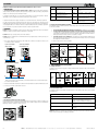
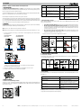
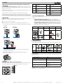
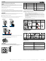
1
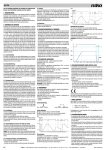
310-0190X
Lees de volledige handleiding vóór installatie en ingebruikname.
symbool
1. BESCHRIJVING
De universele inbouwdraaiknopdimmer plus 5 – 325 W is geschikt om resistieve, inductieve en capacitieve
belastingen alsook dimbare halogeen-, led- en spaarlampen (CFLi) te dimmen. Dit toestel is niet geschikt voor
motorsturing.
De dimmer kan met of zonder geheugen worden gebruikt en is voorzien van een automatische detectie in geval
van een foutconditie (overbelasting, kortsluiting, …).
type lamp
afkorting
type lamp
gloeilamp
LED 1
dimbare ledlamp – faseafsnijding
halogeenlamp met elektronische
transformator
LED 2
dimbare ledlamp – faseaansnijding
halogeenlamp met
elektromagnetische transformator
CFLi 1
dimbare spaarlamp – faseafsnijding
CFLi 2
dimbare spaarlamp – faseaansnijding
De centraalplaat met regelknop en de afdekplaat moeten afzonderlijk worden besteld.
Om de verlichting te dimmen vanop een andere locatie, moet je een draaiknopextensie gebruiken in plaats van
een NO-drukknop. Je kunt tot vijf extra draaiknopextensies (310-0200x) aansluiten op deze dimmer. Ook de
draaiknopextensie moet afzonderlijk worden besteld. Raadpleeg de handleiding van de draaiknopextensie voor
meer informatie over dit product.
3.2. De minimale lichtsterkte instellen
Om het optimale dimniveau van elke lamp te bereiken, stel je de minimale lichtsterkte in. Er zijn drie mogelijkheden:
•• Is de minimale lichtsterkte in orde, dan hoef je niets te wijzigen op de dimmer.
•• Als de lamp op minimaal dimniveau nog te fel brandt, ligt de minimale lichtsterkte te hoog.
Draai de potentiometer op de dimmer met een schroevendraaier naar links om de lichtsterkte te
verlagen. Stop tot net voordat de lamp begint te knipperen of uitgaat.
•• Als de lamp knippert of niet brandt, ligt de minimale lichtsterkte te laag. Draai de potentiometer
op de dimmer met een schroevendraaier naar rechts om de lichtsterkte te verhogen.
2. MONTAGE
Gevaar: Installeer de dimmer niet onder spanning. Sluit het toestel pas na volledige installatie (inclusief centraalplaat
en afdekplaat) aan op de netspanning.
Tip: Gebruik geen gemengde belastingen op één dimmer.
Volgend schema vat deze drie mogelijkheden samen:
Tip: Installeer de dimmer in een omgeving met een niet-condenserende luchtvochtigheid (30 – 70%).
Actie
1. Sluit de dimmer en de belasting(en) aan volgens onderstaand aansluitschema, afhankelijk van het aantal
bedieningspunten:
1 bedieningspunt
230Vac-belasting
Controle
Dimmen tot
minimumniveau
1 bedieningspunt
transformator 12 V
Conclusie
Actie
Minimaal
dimniveau OK
/
Controle
Minimaal
dimniveau te hoog
Minimaal
dimniveau te laag
MIN
OF
MAX
12 V
N
L 230 Vac
N
L 230 Vac
4. WERKING EN GEBRUIK
4.1. Toegelaten belastingen
Volgende tabel geeft een overzicht van de maximale belasting die toegelaten is per lamptype bij een
omgevingstemperatuur van 35°C.
meerdere bedieningspunten*
type lamp
max. 5x 310-0200X
HAL. 230 V
N
L 230 Vac
Verbind de drie aansluitklemmen (N, L, 1) van de dimmer met de gelijknamige aansluitklemmen van de
draaiknopextensie.
*
2. Monteer de dimmer in een inbouwdoos met een inbouwdiepte van minimaal 40 mm.
3. Bevestig alle onderdelen zoals hieronder afgebeeld:
max.
min.
NL
nv Niko sa
325 W
5W
HAL. 12 - 24 V
dimbare
spaarlamp
(max. 10)
dimbare
ledlamp
(max. 10)
325 W
20 W
200 W
5W
200 W
5W
4.2. Normale werking
Deze dimmer werkt volgens het principe van faseaansnijding of faseafsnijding, afhankelijk van de instelling
(zie rubriek 3.1.).
Gebruik van de regelknop
Resultaat
drukken
Je schakelt het licht aan of uit.
draaien
Je regelt de lichtsterkte.
Zodra je de maximale lichtsterkte bereikt hebt,
blijft het dimniveau onveranderd.
snel draaien
Je zorgt voor een snelle daling of stijging van de
lichtsterkte.
traag draaien
Je stelt de lichtsterkte preciezer af.
3. INSTELLINGEN
3.1. Dimmer instellen volgens type lamp
Stel de eerste drie dipswitches achter de regelknop manueel in volgens het type lamp dat je wilt dimmen.
Raadpleeg onderstaand schema voor de juiste instelling van de dipswitches per lamptype.
325 W
5W
HAL. 230 V
Opgelet: De dimmer wordt nooit elektrisch van de netspanning gescheiden. Alle onderdelen blijven onder
netspanning staan, ook al is de belasting (zoals het licht) uitgeschakeld.
Industriepark West 40, BE-9100 Sint-Niklaas, Belgium — tel. +32 3 778 90 00 — fax +32 3 777 71 20 — e-mail: [email protected] — www.niko.eu
PM310-0190XR15023
4.3. Geheugenfunctie
Gebruik
De dimmer is standaard ingesteld zonder geheugenfunctie. Met de vierde dipswitch achter de regelknop zet je
deze functie aan of uit:
Stand van dipswitch
Resultaat
dipswitch naar boven
geheugenfunctie aan
dipswitch naar beneden
geheugenfunctie uit
Vermogen (%)
310-0190X
100%
95%
90%
85%
80%
75%
70%
65%
60%
55%
50%
0
10
20
30
40
50
60
Omgevingstemperatuur (°C)
Het laatst bereikte dimniveau voordat je de dimmer uitschakelt, wordt opgeslaan in het permanente geheugen van
de dimmer als de geheugenfunctie geactiveerd is. Deze waarde gaat niet verloren bij een stroomonderbreking.
Als je de geheugenfunctie activeert, schakelt de dimmer de eerste keer in op het door de fabrikant gekozen
dimniveau. Daarna wordt de verlichting gedimd volgens de laatst ingestelde waarde.
Dimbare spaarlampen dimmen met geheugenfunctie
Het dimprofiel is zo opgebouwd, dat de dimmer kort op zijn maximale lichtsterkte aangeschakeld wordt om daarna
over te gaan naar zijn geheugenstand. Zo kan elke spaarlamp worden aangeschakeld.
5. PROBLEEMOPLOSSING
De werking van de dimmer kan worden verstoord door signalen die over het net verstuurd worden. Dit is geen defect.
Probleem
Oorzaak
Oplossing
De dimmer werkt niet.
De netspanning is niet
aangesloten.
Sluit het toestel aan op de
netspanning.
De belasting is niet aangesloten.
Sluit de belasting correct aan
volgens het aansluitschema.
De toegelaten belasting ligt te
hoog.
Zorg voor een lagere belasting.
De lamp of de draad is defect.
Vervang de lamp of de draad.
Het minimale dimniveau is te laag Zie rubriek 3.2. om het minimale
ingesteld.
dimniveau in te stellen.
De dimmer schakelt zichzelf uit.
De rode led op de dimmer
knippert.
De beveiliging tegen thermische
overbelasting (te hoge
temperatuur) en kortsluiting is in
werking getreden.
Controleer of de belasting niet
te hoog is. Hou hierbij rekening
met het blind vermogen van
gewikkelde transformatoren.
Controleer de temperatuur in de
inbouwdoos (max. 35°C).
Controleer of er gemengde
belastingen gebruikt zijn.
Controleer de
omgevingstemperatuur en
plaatsingsomstandigheden.
Verminder, indien nodig, het
aangesloten vermogen.
7. WAARSCHUWINGEN VOOR INSTALLATIE
-- De installatie moet worden uitgevoerd door een erkend installateur en volgens de geldende voorschriften.
-- Deze handleiding moet aan de gebruiker worden overhandigd. Het moet bij het dossier van de elektrische
installatie worden gevoegd en worden overgedragen aan eventuele nieuwe eigenaars. Bijkomende exemplaren
zijn verkrijgbaar via de website of supportdienst van Niko.
-- Tijdens de installatie moet rekening gehouden worden met (niet-limitatieve lijst):
-- de geldende wetten, normen en reglementen.
-- de stand van de techniek op het moment van de installatie.
-- deze handleiding die alleen algemene bepalingen vermeldt en moet worden gelezen in het kader van
elke specifieke installatie.
-- de regels van goed vakmanschap.
Dit product voldoet aan alle toepasselijke Europese richtlijnen en verordeningen. Indien van toepassing, vind je
de EG-verklaring van overeenstemming met betrekking tot dit product op www.niko.eu.
8. NIKO SUPPORT
Heb je twijfel? Of wil je het product omruilen in geval van een eventueel defect? Neem dan contact op met je
groothandel of de Niko supportdienst:
• België: +32 3 778 90 80
• Nederland: +31 183 64 06 60
Contactgegevens en meer informatie vind je op www.niko.eu onder de rubriek “Hulp en advies”.
9. GARANTIEBEPALINGEN
- De garantietermijn bedraagt vier jaar vanaf leveringsdatum. Als leveringsdatum geldt de factuurdatum
van aankoop van het product door de consument. Als er geen factuur voorhanden is, geldt de
productiedatum.
- De consument is verplicht Niko schriftelijk te informeren over het gebrek aan overeenstemming, en dit
uiterlijk binnen de twee maanden na vaststelling.
- In geval van een gebrek aan overeenstemming heeft de consument enkel recht op een kosteloze herstelling
of vervanging van het product, wat door Niko bepaald wordt.
- Niko is niet verantwoordelijk voor een defect of schade als gevolg van een foutieve installatie, oneigenlijk of
onachtzaam gebruik, een verkeerde bediening, transformatie van het product, onderhoud in strijd met de
onderhoudsvoorschriften of een externe oorzaak zoals vochtschade of schade door overspanning.
- De dwingende bepalingen in de nationale wetgeving over de verkoop van consumptiegoederen en de
bescherming van consumenten in landen waar Niko rechtstreeks of via zuster- of dochtervennootschappen,
filialen, distributeurs, agenten of vaste vertegenwoordigers verkoopt, hebben voorrang op bovenstaande
bepalingen.
Controleer of je de dipswitches
correct ingesteld hebt voor het
lamptype.
6. TECHNISCHE GEGEVENS
voedingsspanning
230 Vac ± 10%, 50 Hz
montage
inbouwdoos met inbouwdiepte van min. 40 mm
gewicht
± 70 g
eigen verbruik
< 0,5 W
max. temperatuur van de behuizing (Tc) bij 35°C (Ta) 90°C
1
max. omgevingstemperatuur (Ta)
zie onderstaande vermogensgrafiek
vermogen1
afhankelijk van de omgevingstemperatuur
(zie onderstaande vermogensgrafiek)
max. draaddiameter per aansluitklem
2 x 2,5 mm²
min. belasting
5W
beveiliging
beveiligd tegen thermische overbelasting en
kortsluiting
max. afstand tussen dimmer en
draaiknopextensie(s)
75 m
normen
EN60669-2-1
Het te dimmen vermogen daalt met 10% per 5°C dat de omgevingstemperatuur van 35°C overschreden wordt.
NL
nv Niko sa
Industriepark West 40, BE-9100 Sint-Niklaas, Belgium — tel. +32 3 778 90 00 — fax +32 3 777 71 20 — e-mail: [email protected] — www.niko.eu
PM310-0190XR15023
310-0190X
Veuillez lire le mode d’emploi entièrement avant l’installation et la mise en service.
symbole
1. DESCRIPTION
Le variateur universel plus encastré à bouton rotatif 5 – 325 W convient pour faire varier l’intensité de
charges résistives, inductives et capacitives ainsi que de lampes halogènes, LED et économiques (CFLi) à intensité
variable. Il ne convient pas pour la commande de moteurs.
Le variateur peut être utilisé avec ou sans fonction de mémorisation et est doté d’un système de détection
automatique en cas de problème de fonctionnement (surcharge, court-circuit, etc.).
type de lampe
abréviation type de lampe
lampe à incandescence
LED 1
LED variable – contrôle de phase
inversé
lampe halogène avec un
transformateur électronique
LED 2
LED variable – contrôle de phase
lampe halogène avec un
transformateur électromagnétique
CFLi 1
lampe à économie d’énergie variable –
contrôle de phase inversé
CFLi 2
lampe à économie d’énergie variable –
contrôle de phase
L’enjoliveur muni du bouton de réglage et la plaque de recouvrement doivent être commandés séparément.
Pour faire varier l’intensité de l’éclairage depuis un autre endroit, vous devez utiliser une extension de bouton
rotatif plutôt qu’un bouton-poussoir NO. Vous pouvez raccorder jusqu’à cinq extensions de bouton rotatif (3100200x) supplémentaires sur ce variateur. L’extension de bouton rotatif doit aussi être commandée séparément.
Pour en savoir plus sur ce produit, consultez le manuel de l’extension de bouton rotatif.
3.2. Réglage de l’intensité lumineuse minimale
Pour atteindre le niveau de variation optimal de chaque lampe, réglez le niveau d’intensité lumineuse minimal.
Il existe trois possibilités:
2. MONTAGE
•• Si le niveau d’intensité lumineuse minimal est satisfaisant, ne modifiez rien sur le variateur.
•• Si le niveau d’intensité lumineuse de la lampe est trop fort au niveau de variation minimal,
cela signifie que le niveau d’intensité minimal est trop élevé. À l’aide d’un tournevis, faites tourner
vers la gauche le potentiomètre qui se trouve sur le variateur, afin de diminuer l’intensité lumineuse.
Arrêtez juste avant que la lampe commence à clignoter ou s’éteigne.
•• Si la lampe clignote ou ne s’allume pas, cela signifie que le niveau d’intensité minimal est trop
bas. À l’aide d’un tournevis, faites tourner vers la droite le potentiomètre qui se trouve sur le variateur,
afin d’augmenter l’intensité lumineuse.
Danger: N’installez pas le variateur en saillie sous tension. Ne raccordez l’appareil à la tension réseau qu’après
installation complète (y compris l’enjoliveur et la plaque de recouvrement).
Conseil: N’utilisez pas de charges mixtes sur un même variateur.
Conseil: Installez le variateur dans un environnement dont le degré hygroscopique de l’air ne prête pas à la
condensation (30 – 70%).
1. Raccordez le variateur et la (les) charge(s) comme indiqué sur le schéma de raccordement ci-dessous, selon
le nombre de points de commande:
1 point de commande
charge 230 Vac
1 point de commande
transformateur 12 V
Le schéma ci-après résume ces trois possibilités:
Action
Vérification
Variation au
minimum
Conclusion
Action
Vérification
Niveau de variation /
minimum OK
Niveau de variation
minimum trop
élevé
Niveau de variation
minimum
trop bas
12 V
N
L 230 Vac
N
L 230 Vac
MIN
OU
MAX
plusieurs points de commande*
4. FONCTIONNEMENT ET UTILISATION
4.1. Charges autorisées
Le tableau ci-dessous donne un aperçu de la charge maximale autorisée par type de lampe à une température
ambiante de 35°C.
max. 5x 310-0200X
N
L 230 Vac
type de
lampe
Reliez les trois bornes de raccordement (N, L, 1) du variateur aux bornes de raccordement homonymes
de l’extension de bouton rotatif.
*
2. Montez le variateur dans une boîte d’encastrement d’une profondeur d’encastrement minimale de 40 mm.
3. Fixez tous les éléments comme illustré ci-dessous:
HAL. 230 V
max.
min.
325 W
5W
HAL. 230 V
325 W
5W
HAL. 12 - 24 V
325 W
20 W
lampe à
économie
d’énergie
variable
(max. 10)
200 W
5W
LED variable
(max. 10)
200 W
5W
4.2. Fonctionnement normal
Ce variateur fonctionne selon le principe du contrôle de phase ou du contrôle de phase inversé, selon le réglage
(voir rubrique 3.1.).
3. RÉGLAGES
3.1. Réglage du variateur selon le type de lampe
Réglez manuellement les trois premiers commutateurs DIP qui se trouvent derrière le bouton de réglage, selon
le type de lampe dont vous souhaitez faire varier l’intensité. Pour connaître le réglage correct des commutateurs
DIP par type de lampe, consultez le schéma ci-dessous.
Utilisation du bouton de réglage
Résultat
appuyer
Vous allumez ou éteignez l’éclairage.
tourner
Vous réglez l’intensité lumineuse.
Lorsque l’intensité lumineuse maximale est
atteinte, le niveau de variation ne change plus.
tourner rapidement
Vous diminuez ou augmentez rapidement l’intensité
lumineuse.
tourner lentement
Vous réglez l’intensité lumineuse avec plus de
précision.
Attention: Le variateur n’est jamais séparé électriquement de la tension réseau. Tous les éléments restent sous
tension, même si la charge (p.ex. l’éclairage) est désactivée.
FR
nv Niko sa
Industriepark West 40, BE-9100 Sint-Niklaas, Belgium — tel. +32 3 778 90 00 — fax +32 3 777 71 20 — e-mail: [email protected] — www.niko.eu
PM310-0190XR15023
4.3. Fonction de mémorisation
Utilisation
Le variateur est livré d’origine sans fonction de mémorisation. Le quatrième commutateur DIP derrière le bouton
de réglage vous permet d’activer ou de désactiver cette fonction:
Position du commutateur DIP
Conséquence
commutateur DIP relevé fonction de mémorisation activée
commutateur DIP
abaissé
fonction de mémorisation désactivée
Puissance (%)
310-0190X
100%
95%
90%
85%
80%
75%
70%
65%
60%
55%
50%
0
10
20
30
40
50
60
Température ambiante (°C)
Le dernier niveau de variation atteint avant que vous désactiviez le variateur est enregistré dans la mémoire
permanente du variateur si la fonction de mémorisation est activée. Cette valeur est conservée en cas de
coupure de courant.
Si la fonction de mémorisation est activée, le variateur s’enclenche la première fois au niveau de variation choisi
par le fabricant. Ensuite, le niveau de variation de l’éclairage correspond à la dernière valeur réglée.
Variation de l’intensité de lampes économiques avec la fonction de mémorisation
Le profil de variation est structuré de manière telle que le variateur s’active brièvement au niveau d’intensité
lumineuse maximale, puis passe à la valeur mémorisée. Chaque lampe à économie d’énergie peut ainsi être allumée.
5. RÉSOLUTION DES PROBLÈMES
7. MISES EN GARDE CONCERNANT L’INSTALLATION
-- L’installation doit être effectuée par un installateur agréé et dans le respect des prescriptions en vigueur.
-- Ce mode d’emploi doit être remis à l’utilisateur. Il doit être joint au dossier de l’installation électrique et être
remis aux nouveaux propriétaires éventuels. Des exemplaires supplémentaires peuvent être obtenus sur le site
web ou auprès du service support de Niko.
-- Il y a lieu de tenir compte des points suivants pendant l’installation (liste non limitative):
-- les lois, les normes et les réglementations en vigueur.
-- l’état de la technique au moment de l’installation.
-- ce mode d’emploi qui stipule uniquement des dispositions générales et doit être lu dans le cadre de
toute installation spécifique.
-- les règles de l’art.
Le fonctionnement du variateur peut être perturbé par des signaux envoyés sur le réseau. Il ne s’agit pas d’une
défectuosité.
Problème
Cause
Solution
Le variateur ne fonctionne pas.
La tension réseau n’est pas
raccordée.
Raccordez l’appareil à la tension
réseau.
La charge n’est pas raccordée.
Raccordez la charge
correctement, selon le schéma
de raccordement.
La charge autorisée est trop
élevée.
Diminuez la charge.
La lampe ou le fil est défectueux. Remplacez la lampe ou le fil.
Le variateur se désactive
spontanément. La LED rouge du
variateur clignote.
Le niveau de variation minimal
réglé est trop faible.
Reportez-vous à la rubrique 3.2.
pour régler le niveau de variation
minimal.
La protection contre les
surcharges thermiques
(température trop élevée) et les
courts-circuits s’est enclenchée.
Contrôlez si la charge n’est
pas trop élevée. Tenez
compte de la puissance
réactive des transformateurs
ferromagnétiques.
Contrôlez la température dans la
boîte d’encastrement (max. 35°C).
Assurez-vous que des charges
mixtes ne sont pas utilisées.
Ce produit est conforme à l’ensemble des directives et règlements européens applicables. Le cas échéant,
vous trouverez la déclaration CE de conformité relative à ce produit sur le site www.niko.eu.
8. SUPPORT DE NIKO
En cas de doute ou si vous voulez échanger le produit en cas de défaut éventuel, veuillez prendre contact
avec votre grossiste ou avec le service support de Niko:
• Belgique: +32 3 778 90 80
• France: +33 820 20 66 25
Vous trouverez les coordonnées et de plus amples informations sur le site www.niko.eu, sous la rubrique
“Aide et conseils”.
9. DISPOSITIONS DE GARANTIE
- Le délai de garantie est de quatre ans à partir de la date de livraison. La date de la facture d’achat par le consommateur
est considérée comme la date de livraison. En l’absence de facture, la date de fabrication est valable.
- Le consommateur est tenu de prévenir Niko par écrit de tout défaut de conformité, dans un délai maximum
de deux mois après constatation.
- En cas de défaut de conformité, le consommateur peut uniquement prétendre à la réparation gratuite ou au
remplacement gratuit du produit, selon l’avis de Niko.
- Niko ne peut être tenu pour responsable d’un défaut ou de dégâts résultant d’une installation fautive, d’une
utilisation impropre ou négligente, d’une commande erronée, d’une transformation du produit, d’un entretien
contraire aux consignes d’entretien ou d’une cause externe telle que de l’humidité ou une surtension.
- Les dispositions contraignantes de la législation nationale ayant trait à la vente de biens de consommation
et à la protection des consommateurs des différents pays où Niko procède à la vente directe ou
par l’intermédiaire d’entreprises sœurs, de filiales, de succursales, de distributeurs, d’agents ou de
représentants fixes, prévalent sur les dispositions susmentionnées.
Contrôlez la température
ambiante et les conditions de
pose. Si nécessaire, diminuez la
puissance raccordée.
Contrôlez si les commutateurs
DIP sont réglés correctement
pour le type de lampe.
6. CARACTÉRISTIQUES TECHNIQUES
1
tension d’alimentation
230 Vac ± 10%, 50 Hz
montage
boîte d’encastrement d’une profondeur
d’encastrement de 40 mm min.
poids
± 70 g
consommation propre
< 0,5 W
température max. du boîtier (Tc) à 35°C (Ta)
90°C
température ambiante max. (Ta)
voir graphique de la puissance ci-dessous
puissance1
selon la température ambiante
(voir graphique de la puissance ci-dessous)
diamètre max. du fil par borne de raccordement
2 x 2,5 mm²
charge min.
5W
protection
protégé contre les surcharges thermiques et les
courts-circuits
distance max. entre le variateur et la (les)
extension(s) de bouton rotatif
75 m
normes
EN60669-2-1
La puissance à faire varier diminue de 10% par 5°C au-delà de la température ambiante de 35°C.
FR
nv Niko sa
Industriepark West 40, BE-9100 Sint-Niklaas, Belgium — tel. +32 3 778 90 00 — fax +32 3 777 71 20 — e-mail: [email protected] — www.niko.eu
PM310-0190XR15023
310-0190X
Handbuch vor Montage und Inbetriebnahme vollständig durchlesen.
Symbol
1. BESCHREIBUNG
Der Universal Unterputz-Drehdimmer Plus 5 – 325 W eignet sich zum Dimmen von resistiven, induktiven
und kapazitiven Lasten sowie für die Ansteuerung von dimmbaren Halogen-, LED- und Energiesparlampen (CFLi).
Dieses Gerät eignet sich nicht für die Motoransteuerung.
Sie können den Dimmer mit oder ohne Speicherfunktion betreiben. Für den Störungszustand (Kurzschluss,
Überlast etc.) verfügt der Dimmer über eine automatische Störerfassung.
Leuchtmitteltyp
Abkürzung Leuchtmitteltyp
Glühlampe
LED 1
dimmbare LED-Lampe –
Phasenabschnitt
Halogenlampe mit elektronischem
Transformator
LED 2
dimmbare LED-Lampe –
Phasenanschnitt
Halogenlampe mit
elektromagnetischem Transformator
CFLi 1
dimmbare Energiesparlampe –
Phasenabschnitt
CFLi 2
dimmbare Energiesparlampe –
Phasenanschnitt
Die Zentralplatte mit Regelknopf und die Blende sind separat zu bestellen.
Um die Beleuchtung von einer anderen Stelle aus dimmen zu können, benötigen Sie anstelle eines Schließertasters eine Drehknopferweiterung. Sie können an diesen Dimmer bis zu fünf zusätzliche Drehknopferweiterungen
(310-0200x) anschließen. Eine Drehknopferweiterung muss separat bestellt werden. Weitere Informationen über
dieses Produkt entnehmen Sie bitte dem Handbuch der Drehknopferweiterung.
3.2. Mindestlichtstärke einstellen
Für ein optimales Dimmniveau der einzelnen Lampen müssen Sie die Mindestlichtstärke einstellen. Hierfür
haben Sie drei Möglichkeiten:
2. MONTAGE
•• Ist die Mindestlichtstärke in Ordnung, dann brauchen Sie keine Änderungen am Dimmer vornehmen.
•• Wenn die Lampe bei minimalem Dimmniveau zu grell leuchtet, dann ist die Mindestlichtstärke
zu hoch eingestellt. Um die Lichtstärke zu reduzieren, müssen Sie mit einem Schraubendreher das
Potentiometer des Dimmers nach links verstellen. Stoppen Sie die Verstellung kurz bevor die Lampe
zu flackern beginnt oder gar erlischt.
•• Wenn die Lampe flackert oder nicht mehr leuchtet, dann ist die Mindestlichtstärke zu niedrig
eingestellt. Um die Lichtstärke heraufzusetzen, müssen Sie mit einem Schraubendreher das
Potentiometer des Dimmers nach rechts verstellen.
Gefahrenhinweis: Dimmer niemals unter Spannung installieren. Schließen Sie das Gerät erst nach vollständiger
Installation (inkl. Zentralplatte und Blende) an die Netzspannung an.
Tipp: Steuern Sie mit 1 Dimmer keine unterschiedlichen Lasttypen an.
Tipp: Installieren Sie den Dimmer in einer Betriebsumgebung mit nicht-kondensierender Luftfeuchte (30 – 70 %).
1. Schließen Sie Dimmer und Last(en) je nach Anzahl der Bedienungspunkte gemäß untenstehendem
Anschlussplan an:
1 Bedienungspunkt
230 Vac-Last
1 Bedienungspunkt
Transformator 12 V
Folgendes Schema fasst die genannten drei Möglichkeiten zusammen:
Massnahme
Anzeige
Auf Mindestdimmniveau herabdimmen
Erklärung
Massnahme
Anzeige
Mindestdimmniveau /
ist OK
Mindestdimmniveau
ist zu hoch
12 V
N
L 230 Vac
Mindestdimmniveau
ist zu niedrig
N
L 230 Vac
MIN
mehrere Bedienungspunkte*
ODER
MAX
4. FUNKTIONSWEISE UND BETRIEB
4.1. Zugelassene Lastwerte
Untenstehende Tabelle enthält eine Übersicht über die Maximalbelastung der einzelnen Leuchtmitteltypen bei
einer Umgebungstemperatur von 35°C.
max. 5x 310-0200X
N
L 230 Vac
Leuchtmitteltyp
Verbinden Sie die drei Anschlussklemmen (N, L, 1) des Dimmers mit den gleichnamigen
Anschlussklemmen der Drehknopferweiterung.
*
2. Montieren Sie die Dimmer in einer Unterputzdose einer Einbautiefe von mind. 40 mm.
3. Bestätigen Sie alle Komponenten wie untenstehend abgebildet:
HAL. 230 V
max.
min.
325 W
5W
HAL. 230 V
325 W
5W
HAL. 12 - 24 V
325 W
20 W
dimmbare
Energiesparlampe
(max. 10)
200 W
5W
dimmbare
LED-Lampe
(max. 10)
200 W
5W
4.2. Normalbetrieb
Dieser Dimmer wendet je nach Einstellung das Phasenanschnitts- oder Phasenabschnittsprinzip an (Siehe
Abschnitt 3.1.).
Betätigungsart des Regelknopfs
3. EINSTELLUNGEN
3.1. Dimmer nach Leuchtmitteltyp einstellen
Stellen Sie die ersten drei hinterm Regelknopf befindlichen DIP-Schalter manuell gemäß Ausführung der
zu dimmenden Lampe ein. Einstellung des Leuchtmitteltyps über die DIP-Schalter nach den Angaben des
untenstehenden Schemas.
Ergebnis
Betätigung (drücken)
Hiermit schalten Sie das Licht ein oder aus.
Regelknopf drehen
Hiermit regeln Sie die Lichtstärke.
Sobald Sie die maximale Lichtstärke erreicht haben,
bleibt das Dimmniveau unverändert bestehen.
schnelle Drehung
Hierüber regeln Sie die Lichtstärke schnell herunter
oder herauf.
langsame Drehung
Hiermit stellen Sie die Lichtstärke ganz genau nach
Wunsch ein.
Achtung: Der Dimmer wird niemals von der Netzspannung getrennt. Alle Komponenten stehen auch bei
ausgeschalteter Beleuchtung weiterhin unter Netzspannung.
DE
nv Niko sa
Industriepark West 40, BE-9100 Sint-Niklaas, Belgium — tel. +32 3 778 90 00 — fax +32 3 777 71 20 — e-mail: [email protected] — www.niko.eu
PM310-0190XR15023
4.3. Speicherfunktion
Anwendung
Standardmäßig ist die Speicherfunktion des Dimmers deaktiviert. Sie können die Speicherfunktion jedoch mit
dem vierten hinterm Regelknopf befindlichen DIP-Schalter aktivieren oder deaktivieren:
Stellung von DIP-Schalter
Speicherfunktion
DIP-Schalter oben
Speicherfunktion ist an
DIP-Schalter unten
Speicherfunktion ist aus
Leistung (%)
310-0190X
100%
95%
90%
85%
80%
75%
70%
65%
60%
55%
50%
0
10
20
30
40
50
60
Umgebungstemperatur (°C)
Der zuletzt vor Abschalten des Dimmers eingestellte Lichtstärkewert wird bei eingeschalteter Speicherfunktion
im Permanentspeicher des Dimmers abgespeichert. Dieser Wert geht selbst bei einer Spannungsunterbrechung
nicht verloren.
Wenn Sie die Speicherfunktion aktivieren, gibt der Dimmer beim ersten Einschalten den vom Hersteller
voreingestellten Lichtstärkewert vor. Danach wird die Beleuchtung nach dem zuletzt eingestellten Wert gedimmt.
Dimmbare Energiesparlampen mit Speicherfunktion dimmen
Laut Dimmprofil gibt der Dimmer nach dem Einschalten kurz die max. Lichtstärke vor, um danach auf die
gespeicherte Lichtstärke zu regeln. Dadurch lassen sich alle Energiesparlampen einschalten.
5. STÖRUNGSABHILFE
Die Funktion eines Dimmers kann von über das Stromnetz eintreffenden Störsignalen beeinträchtigt werden.
Hierbei handelt es sich nicht um einen Defekt des Dimmers.
7. WARNHINWEISE FÜR DIE INSTALLATION
-- Die Installation darf ausschließlich von einer Elektrofachkraft unter Berücksichtigung der geltenden
Vorschriften ausgeführt werden.
-- Diese Gebrauchsanleitung muss dem Benutzer ausgehändigt werden. Die Gebrauchsanleitung ist den Unterlagen
der elektrischen Anlage beizufügen und muss auch eventuellen neuen Besitzern ausgehändigt werden.
Zusätzliche Exemplare erhalten Sie über die Internetseiten von Niko oder über den Kundendienst von Niko.
-- Beachten und berücksichtigen Sie bei der Installation unter anderem folgende Punkte:
-- die gültigen Gesetze, Normen und Richtlinien.
-- den Stand der Technik zum Zeitpunkt der Installation.
-- die in dieser Gebrauchsanleitung aufgeführten Anweisungen, wobei diese Gebrauchsanleitung nur
allgemein gültige Bestimmungen enthält, die für jede Anlage spezifisch angewendet werden müssen.
-- die allgemein anerkannten Regeln fachmännischer Arbeit.
Problem
Ursache
Lösung
Dieses Produkt erfüllt alle anwendbaren europäischen Richtlinien und Verordnungen. Die für dieses Produkt
zutreffende EG-Konformitätserklärung erhalten Sie gegebenenfalls unter www.niko.eu.
Dimmer funktioniert nicht mehr.
Netzspannung ist nicht
angeschlossen.
Gerät an Netzspannung
anschließen.
8. NIKO UNTERSTÜTZUNG
Schaltlast ist nicht
angeschlossen.
Schaltlast korrekt gemäß
Anschlussplan anschließen.
Die zulässige Schaltlast ist zu
hoch.
Sorgen Sie für eine niedrigere
Schaltlast.
Defekte Lampe bzw. Verdrahtung Lampe bzw. Anschlusskabel
austauschen.
Dimmer schaltet von selbst aus.
Die auf dem Dimmer befindliche
rote LED blinkt.
Es wurde eine zu niedrige
Mindestlichtstärke eingestellt.
Siehe zur Einstellung der
Mindestlichtstärke auch
Abschnitt 3.2.
Der Schutz gegen thermische
Überlast (zu hohe Temperatur)
und Kurzschluss hat ausgelöst.
Überprüfen Sie, ob die
Belastung nicht zu hoch ist.
Berücksichtigen Sie dabei die
Blindleistung von Wickeltrafos.
Überprüfen Sie die in der
Unterputzdose herrschende
Temperatur (max. 35 °C).
Überprüfen Sie, ob
unterschiedliche Lasttypen
verwendet werden.
Bei Zweifel oder falls Sie bei einem eventuellen Defekt des Produkts noch Fragen bezüglich des Umtausches
haben, dann nehmen Sie bitte Kontakt auf mit dem Kundendienst von Niko (Belgien: +32 3 778 90 80) oder
wenden Sie sich an Ihren Großhändler. Kontaktdaten und weitere Informationen erhalten Sie im Internet unter
www.niko.eu in der Rubrik “Unterstützung und Beratung”.
9. GARANTIEBEDINGUNGEN
- Der Garantiezeitraum beträgt vier Jahre ab Lieferdatum. Als Lieferdatum gilt das Rechnungsdatum zum Zeitpunkt
des Kaufs durch den Endverbraucher. Falls keine Rechnung mehr vorhanden ist, gilt das Produktionsdatum.
- Der Endverbraucher ist verpflichtet, Niko schriftlich über einen Produktmangel innerhalb von zwei Monaten
nach dessen Feststellung zu informieren.
- Im Falle eines Mangels hat der Endverbraucher nur Recht auf kostenlose Reparatur oder Ersatz des
Produkts. Eine Entscheidung darüber obliegt allein Niko.
- Niko ist nicht für Mängel oder Schäden verantwortlich, die durch fehlerhafte Installation, nicht
bestimmungsgemäßen oder unsachgemäßen Gebrauch, durch falsche Bedienung, Anpassen/Ändern des
Produktes, infolge von unsachgemäßer Wartung entgegen den Wartungsvorschriften oder die sich aus
äußeren Umständen, wie beispielsweise infolge Feuchtigkeit oder Überspannung, ergeben.
- Zwingende Vorschriften der nationalen Gesetzgebung bezüglich des Verkaufs von Konsumgütern und zum
Verbraucherschutz haben vor den obigen Bestimmungen Vorrang in den Ländern, in denen Niko direkt oder
über seine Neben- oder Tochtergesellschaften, Filialen, Vertriebsstellen, Agenten oder über feste Vertreter
verkauft.
Überprüfen Sie die
Umgebungstemperatur und
die Montagegegebenheiten.
Verringern Sie nötigenfalls die
angeschlossene Leistung.
Überprüfen Sie, ob die DIPSchalter korrekt auf den
Leuchtmitteltyp eingestellt
wurden.
6. TECHNISCHE DATEN
1
Versorgungsspannung
230 Vac ± 10%, 50 Hz
Montage
Unterputzdose mit Einbautiefe von mind. 40 mm
Gewicht
± 70 g
Eigenverbrauch
< 0,5 W
max. Gehäusetemperatur (Tc) bei 35°C (Ta)
90°C
max. Umgebungstemperatur (Ta)
siehe untenstehende Leistungsgrafik
Leistung1
abhängig von der Umgebungstemperatur (siehe
untenstehende Leistungsgrafik)
max. Anschlussquerschnitt pro Anschlussklemme
2 x 2,5 mm²
Minimallast
5W
Absicherung
versehen mit Schutz gegen thermische Überlast
und Kurzschluss
max. Abstand zwischen Dimmer und
Drehknopferweiterung(en)
75 m
Normen
EN60669-2-1
Die zu dimmende Leistung sinkt um 10% je 5°C ab, die ab einer Umgebungstemperatur von 35°C überschritten wird.
DE
nv Niko sa
Industriepark West 40, BE-9100 Sint-Niklaas, Belgium — tel. +32 3 778 90 00 — fax +32 3 777 71 20 — e-mail: [email protected] — www.niko.eu
PM310-0190XR15023
310-0190X
Read the complete user manual before carrying out the installation and activating the system.
symbol
1. DESCRIPTION
The universal flush-mounting rotary dimmer plus 5 – 325 W is suitable for the dimming of resistive,
inductive and capacitive loads as well as dimmable halogen, LED and economy (CFLi) lamps. This device is not
suitable for the control of motors.
The dimmer can be used with or without memory and is equipped with automatic detection in the event of a
system defect (overload, short circuit, ...).
type of lamp
abbreviation
incandescent lamp
LED 1
dimmable LED lamp – reverse phase
control
halogen lamp with an electronic
transformer
LED 2
dimmable LED lamp – phase control
halogen lamp with an electromagnetic CFLi 1
transformer
dimmable economy lamp – reverse
phase control
CFLi 2
dimmable economy lamp – phase
control
The central plate with the control button and the flush surround plate must be ordered separately.
To dim the lighting from a different location, you must use a rotary button extension instead of an NO push button.
You can connect up to five extra rotary button extensions (310-0200x) to this dimmer. The rotary button extension
must also be ordered separately. Consult the rotary button extension manual for more information about this product.
2. INSTALLATION
3.2. Selecting the minimum light intensity
In order to achieve the optimal dimming level of each lamp, adjust the minimum light intensity. There are three
possibilities:
Danger: Disconnect all power before installing the dimmer. Do not connect the device to the mains voltage until
installation has been completed (including the central plate and flush surround plate).
•• If the minimum light intensity is satisfactory, you do not need to adjust the dimmer.
•• If the light is too bright at the minimum dimming level, the minimum light intensity is set too
high. Use a screwdriver to turn the potentiometer on the dimmer counterclockwise to decrease the
minimum light intensity. Stop until just before the light starts flickering or is dimmed completely.
•• If the light is flickering or not bright enough, the minimum light intensity is set too low. Turn the
potentiometer on the dimmer clockwise with a screwdriver to increase the minimum light intensity.
Tip: Do not use mixed loads on one single dimmer.
Tip: Install the dimmer in an environment with a non-condensing atmospheric humidity (30 – 70%).
1. Connect the dimmer and the load(s) according to the wiring diagram below, depending on the number of
control points:
1 control point
230 Vac load
1 control point
12 V transformer
type of lamp
Check the diagram below for a summary of available options.
Action
Check
Dim to minimum
Conclusion
Action
Minimum dimming
level OK
/
Check
Minimum dimming
level too high
Minimum dimming
level too low
12 V
N
L 230 Vac
N
L 230 Vac
MIN
OR
MAX
several control points*
4. OPERATION AND USE
4.1. Maximum permitted load
Check the table below to find out the maximum load for each type of lamp at an ambient temperature of 35°C.
max. 5x 310-0200X
type of
lamp
N
L 230 Vac
HAL. 230 V
*
Connect the three connection terminals (N, L, 1) of the dimmer to the corresponding connection
terminals of the rotary button extension.
2. Mount the dimmer in a flush-mounting box with a flush-mounting depth of at least 40 mm.
3. Secure all parts as shown below:
max.
min.
325 W
5W
325 W
20 W
dimmable
economy
lamp
(max. 10)
200 W
5W
dimmable
LED lamp
(max. 10)
200 W
5W
4.2. Normal operation
This dimmer works according to the phase control or the reverse phase control principle, depending on the
setting (see section 3.1.).
Use of the control button
Result
pressing
You switch the light on or off.
rotating
You adjust the light intensity.
As soon as you reach the maximum light intensity,
the dimming level remains unchanged.
rotating quickly
You produce a rapid decrease or increase in the
light intensity.
rotating slowly
You produce a rapid decrease or increase in the
light intensity.
3. SETTINGS
3.1. Adjusting the dimmer settings according to the type of lamp
Manually adjust the first three DIP switches behind the control button according to the type of lamp that you want
to dim. Check the diagram below to find out the correct DIP switch settings for each type of lamp.
325 W
5W
HAL. 230 V
HAL. 12 - 24 V
Attention: The dimmer is never electrically separated from the mains voltage. All parts remain connected to the
mains voltage even if the load (e.g. the light) is off.
EN
nv Niko sa
Industriepark West 40, BE-9100 Sint-Niklaas, Belgium — tel. +32 3 778 90 00 — fax +32 3 777 71 20 — e-mail: [email protected] — www.niko.eu
PM310-0190XR15023
4.3. Memory function
Use
The standard setting of the dimmer is without memory function. You can use the fourth DIP switch behind the
control button to activate or deactivate this function:
DIP switch position
Result
DIP switch up
memory function on
DIP switch down
memory function off
Capacity (%)
310-0190X
100%
95%
90%
85%
80%
75%
70%
65%
60%
55%
50%
0
10
20
30
40
50
60
Ambient temperature (°C)
The last dimming level set before switching off the dimmer is saved in the permanent memory of the dimmer if
the memory function is activated. In the event of a power failure, this value will not be lost.
If the memory function is activated, the dimmer switches on for the first time at the default dimming level chosen
by the manufacturer. Thereafter, the lighting will be dimmed at the last set value.
Dimming dimmable economy lamps with memory function
The dimming profile is set up so that the dimmer is first switched on to its maximum light intensity for a short
time and then returns to the dimming level saved in memory. All economy lamps can be switched on like this.
5. TROUBLESHOOTING
The operation of the dimmer can be disturbed by signals that are sent over the mains. This is not a defect.
Problem
Cause
Action
The dimmer does not work.
The mains voltage is not
connected.
Connect the device to the mains
voltage.
The load is not connected.
Connect the load correctly as
shown in the wiring diagram.
The allowable load is too high.
Provide for a lower load.
The lamp or the wire is defective. Replace the lamp or the wire.
The dimmer switches itself off.
The red LED on the dimmer
flashes.
The minimum dimming level has
been set too low.
See section 3.2. to set the minimum dimming level.
The thermal overload
(temperature too high) and the
short-circuit protection have
been activated.
Check whether the load is too
high. When doing this, keep
in mind the reactive power of
ferromagnetic transformers.
Check the temperature in the
flush-mounting box (max. 35°C).
Check whether mixed loads are
being used.
Check the ambient temperature
and the positioning conditions. If
necessary, reduce the connected
capacity.
7. WARNINGS REGARDING INSTALLATION
-- The installation should be carried out by a registered installer and in compliance with the statutory
regulations.
-- This user manual should be presented to the user. It should be included in the electrical installation file, and
it should be passed on to any new owners. Additional copies are available on the Niko website or via the
Niko support service.
-- During installation, the following should be taken into account (non-exhaustive list):
-- the statutory laws, standards and regulations.
-- the technology currently available at the time of installation.
-- this user manual, which only states general regulations and should therefore be read within the scope of
each specific installation.
-- the rules of proper workmanship.
This product complies with all of the relevant European guidelines and regulations. If applicable, you can find
the EC declaration of conformity regarding this product at www.niko.eu.
8. NIKO SUPPORT
In case of doubt or for the specific exchange procedure in case of a possible defect, contact the Niko support
service in Belgium at +32 3 778 90 80 or your wholesaler/installer. Contact details and more information can
be found at www.niko.eu under the “Help and advice” section.
9. GUARANTEE PROVISIONS
- The period of guarantee is four years from the date of delivery. The delivery date is the invoice date of
purchase of the product by the consumer. If there is no invoice, the date of production applies.
- The consumer is obliged to inform Niko in writing about the non-conformity, within two months after stating
the defect.
- In case of a non-conformity, the consumer only has the right to a product repair or replacement free of
charge, which shall be decided by Niko.
- Niko shall not be held liable for a defect or damage resulting from incorrect installation, improper or
careless use, incorrect operation, transformation of the product, maintenance that does not adhere to the
maintenance instructions or an external cause, such as damage due to moisture or overvoltage.
- The compulsory regulations of the national legislation concerning the sale of consumer goods and the
protection of the consumer in the countries where Niko sells, directly or via sister companies, subsidiaries,
chain stores, distributors, agents or permanent sales representatives, take priority over the above-mentioned
rules and regulations.
Check whether you have set the
DIP switches correctly for the
type of lamp used.
6. TECHNICAL DATA
1
power supply voltage
230 Vac ± 10%, 50 Hz
mounting
flush-mounting box with flush-mounting depth of
min. 40 mm
weight
± 70 g
no-load power consumption
< 0,5 W
max. housing temperature (Tc) at 35°C (Ta)
90°C
max. ambient temperature (Ta)
see capacity graph below
capacity1
dependent on the ambient temperature
(see capacity graph below)
max. wire diameter per connection terminal
2 x 2,5 mm²
min. load
5W
protection
protected against thermal overload and shortcircuit
max. distance between dimmer and rotary button
extension(s)
75 m
standards
EN60669-2-1
The capacity to be dimmed drops 10% for every 5°C that the ambient temperature rises above 35°C.
EN
nv Niko sa
Industriepark West 40, BE-9100 Sint-Niklaas, Belgium — tel. +32 3 778 90 00 — fax +32 3 777 71 20 — e-mail: [email protected] — www.niko.eu
PM310-0190XR15023
310-0190X
Pred inštaláciou a spustením systému si prečítajte celý návod.
symbol
1. POPIS
Univerzálny otočný stmievač plus pre zapustenú montáž (5 – 325 W) je vhodný na stmievanie odporových,
indukčných a kapacitných záťaží ako aj stmievateľných halogénových žiaroviek, LED a úsporných žiaroviek (CFLi).
Zariadenie nie je vhodné na ovládanie motorov.
typ svetelnej záťaže
skratka
typ svetelnej záťaže
žiarovka
LED 1
stmievateľná LED – reverzné riadenie
halogénová žiarovka s elektronickým
transformátorom
LED 2
stmievateľná LED – fázové riadenie
halogénová žiarovka s
CFLi 1
elektromagnetickým transformátorom
Stmievač je možné použiť s pamäťou alebo bez nej a je vybavený automatickou detekciou v prípade poruchy
systému (preťaženie, skrat...).
stmievateľná úsporná žiarovka – reverzné riadenie
CFLi 2
stmievateľná úsporná žiarovka –
fázové riadenie
Stredový kryt s ovládačom a rámček sa objednávajú samostatne.
Ak chcete využiť funkciu stmievania z iného miesta, namiesto tlačidla NO musíte použiť rozšírenie otočného spínača. K
tomuto stmievaču je možné pripojiť až päť rozšírení otočného spínača extra (310-0200x). Rozšírenie otočného spínača
je potrebné objednať samostatne. Viac informácií o tomto výrobku nájdete v príručke pre rozšírenie otočného spínača.
3.2. Nastavenie minimálnej intenzity osvetlenia
Pre dosiahnutie optimálnej úrovne stmievania každej svetelnej záťaže upravte minimálnu intenzitu svetla. Existujú
tri možnosti:
2. INŠTALÁCIA
•• V prípade, že minimálna intenzita svetla je uspokojivá, stmievače upravovať nemusíte.
•• Ak je svetlo pri minimálnej úrovni stmievania príliš silné, minimálna svetelná intenzita je
nastavená príliš vysoko. Na zníženie minimálnej intenzity osvetlenia skrutkovačom otočte potenciometer
na stmievači proti smeru hodinových ručičiek. Pokračujte, až kým svetlo nezačne blikať alebo nie
je úplne stmavené.
•• Ak svetlo bliká alebo nie dostatočne silné, minimálna svetelná intenzita je nastavená príliš
nízko. Na zvýšenie minimálnej intenzity osvetlenia skrutkovačom otočte potenciometer na stmievači
v smere hodinových ručičiek.
Nebezpečenstvo: Pred inštaláciou stmievača odpojte všetky napájacie zdroje. Nepripájajte zariadenie k napájaciemu zdroju až do dokončenia inštalácie (vrátane stredového krytu a rámčeka).
Tip: Nepoužívajte jeden stmievač pre rôzne záťaže.
Tip: Stmievač inštalujte len v prostredí s takou vlhkosťou vzduchu, pri ktorej nedochádza ku kondenzácii (30% – 70%).
1. Stmievač a záťaž(e) zapojte podľa schémy nižšie v závislosti od počtu ovládacích bodov:
1 ovládací bod
230 Vac záťaž
Pre prehľad dostupných možností pozrite tabuľku nižšie.
1 ovládací bod
12 V transformátor
Akcia
Skontrolujte
Stmievanie na
minimum
Záver
Akcia
Minimálna úroveň
stmievania OK
/
Skontrolujte
Minimálna úroveň
stmievania príliš
vysoká
12 V
N
L 230 Vac
N
L 230 Vac
Minimálna úroveň
stmievania príliš
nízka
niekoľko ovládacích bodov*
MIN
alebo
MAX
4. PREVÁDZKA A POUŽÍVANIE
4.1. Maximálna povolená záťaž
Pozrite sa na nižšie uvedenú tabuľku, pre zistenie maximálnej povolenej záťaže jednotlivého typu osvetlenia pri
prevádzkovej teplote 35°C.
max. 5x 310-0200X
N
L 230 Vac
*
Tri svorky (N, L, 1) stmievača pripojte k zodpovedajúcim pripojovacím svorkám rozšírenia otočného spínača.
typ svetelnej
záťaže
2. Pripevnite stmievač do montážnej krabice s hĺbkou zapustenia aspoň 40 mm.
3. Všetky časti zabezpečte podľa obrázka nižšie:
HAL. 230 V
max.
min.
325 W
5W
HAL. 230 V
325 W
5W
HAL. 12 - 24 V
325 W
20 W
stmievateľná
stmievateľná
úsporná
LED
žiarovka
žiarovka
(max. 10)
(max. 10)
200 W
5W
5W
4.2. Manuálne ovládanie
Tento stmievač pracuje na princípe fázového riadenia alebo reverzného fázového riadenia, v závislosti od
nastavenia (pozrite časť 3.1.).
3. NASTAVENIA
3.1. Prispôsobenie nastavenia stmievača podľa typu svetelnej záťaže
Manuálne nastavte prvé tri DIP prepínače za ovládacím tlačidlom podľa typu svetelnej záťaže, ktorú chcete stmievať.
Pre zistenie správneho nastavenia DIP prepínačov pre každý typ svietidla pozrite tabuľku nižšie.
Používanie ovládacieho tlačidla
Výsledok
stlačenie
Zapnete alebo vypnete osvetlenie.
otáčanie
Prispôsobujete intenzitu osvetlenia.
Keď sa dostanete na maximálnu intenzitu osvetlenia, jeho úroveň sa viac nemení.
rýchle otočenie
Umožní rýchly pokles alebo nárast intenzity
osvetlenia.
pomalé otáčanie
Prispôsobujete intenzitu osvetlenia s väčšou
presnosťou.
Upozornenie: Stmievač sa nikdy elektricky neoddeľuje od sieťového napätia. Všetky súčasti preto zostávajú
pripojené k sieťovému napätiu, a to aj vtedy, keď je záťaž (napr. žiarovka) vypnutá.
SK
nv Niko sa
Industriepark West 40, BE-9100 Sint-Niklaas, Belgium — tel. +32 3 778 90 00 — fax +32 3 777 71 20 — e-mail: [email protected] — www.niko.eu
PM310-0190XR15023
4.3. Pamäť
Použitie
Štandardné nastavenie stmievača je bez pamäte. Na zapnutie alebo vypnutie tejto funkcie môžete použiť štvrtý
DIP prepínač za ovládacím tlačidlom:
Poloha DIP prepínača
Výsledok
DIP prepínač hore
funkcia pamäte zapnutá
DIP prepínač dole
funkcia pamäte vypnutá
kapacita (%)
310-0190X
100%
95%
90%
85%
80%
75%
70%
65%
60%
55%
50%
0
10
20
30
40
50
60
teploty okolia (°C)
Ak je funkcia pamäte zapnutá, v trvalej pamäti stmievača je uložená posledná úroveň stmievania pred vypnutím
stmievača. Táto hodnota ostane v pamäti aj v prípade výpadku elektrickej energie.
Ak je funkcia pamäte zapnutá, stmievač sa prvýkrát zapne pri úrovni osvetlenia zvolenej výrobcom. Osvetlenie
sa následne zapne s poslednou nastavenou hodnotou.
Stmievanie stmievateľných úsporných žiaroviek s funkciou pamäte
Profil stmievania je nastavený tak, že stmievač sa najprv na krátko zapne na maximálnu intenzitu osvetlenia
a potom sa vráti na úroveň uloženú v pamäti. Všetky úsporné žiarovky je možné zapínať takýmto spôsobom.
5. RIEŠENIE PROBLÉMOV
Prevádzka stmievača môže byť narušená signálmi, ktoré sú odosielané cez elektrickú sieť. Nie je to chyba.
Problém
Príčina
Akcia
Stmievač nefunguje.
Sieťové napätie nie je pripojené.
Pripojte zariadenie do elektrickej
siete.
Záťaž nie je pripojená.
Pripojte záťaž správne, ako je
uvedené v schéme zapojenia.
Prípustné zaťaženie je príliš
vysoké.
Zabezpečte zníženie zaťaženia.
Žiarovky alebo drôt sú chybné.
Vymeňte žiarovku alebo drôt.
Minimálna úroveň stmievania
bola nastavená príliš nízko.
Spôsob nastavenia minimálnej
úrovne stmievania nájdete v
časti 3.2.
Bola aktivovaná ochrana proti
tepelnému preťaženiu (teplota
príliš vysoká) a ochrana proti
skratu.
Skontrolujte, či zaťaženie
nie je príliš veľké. Dávajte
si pritom pozor na jalový
výkon feromagnetických
transformátorov.
Stmievač sa automaticky vypne.
Červená LED na stmievači bliká.
Skontrolujte teplotu v inštalačnej
krabici (maximálne 35 °C).
7. PRÁVNE UPOZORNENIA
-- Inštaláciu musí vykonať autorizovaný oprávnený pracovník a musí byť v súlade so zákonnými predpismi a
normami.
-- Táto užívateľská príručka musí byť odovzdaná používateľovi. Musí byť súčasťou súboru dokumentácie k
elektrickej inštalácii a musí byť odovzdaná každému ďalšiemu vlastníkovi. Ďalšie kópie sú k dispozícii na
webovej stránke Niko alebo prostredníctvom služby podpory.
-- Počas inštalácie treba brať ohľad na nasledovné (nie len body uvedené v tomto zozname):
-- Zákonné predpisy, normy a regulácie.
-- Aktuálny stav technológie v čase inštalácie.
-- Túto užívateľskú príručku, ktorá uvádza iba všeobecné predpisy a musí byť naštudovaná v rozsahu
potrebnom k danej inštalácii.
-- Pravidlá správneho vypracovania.
8. NIKO PODPORA
V prípade pochybností alebo potreby výmeny konkrétneho komponentu v prípade chyby sa obráťte na servisnú
podporu Niko v Belgicku na +32 3 778 90 80 alebo na vášho predajcu/technika. Kontaktné údaje a ďalšie
informácie možno nájsť na www.niko.eu v časti “Pomoc a poradenstvo”.
9. USTANOVENIA ZÁRUKY
- Záručná lehota je štyri roky od dátumu dodania. Dátumom dodania je dátum vyfakturovania nákupu
produktu spotrebiteľovi. V prípade neexistencie faktúry platí dátum výroby.
- Zákazník je povinný písomne informovať spoločnosť Niko o vade do dvoch mesiacov od zistenia poruchy.
- V prípade nesplnenia funkčnosti má zákazník právo na bezplatnú opravu alebo náhradu (rozhodne firma
Niko).
- Spoločnosť Niko nezodpovedá za poruchu alebo poškodenie v dôsledku nesprávnej inštalácie,
nevhodného alebo nedbalého používania, alebo nesprávneho zaobchádzania alebo úpravy tovaru.
Podobne nezodpovedá ani v prípade údržby, ktorá sa nevykonávala v súlade s pokynmi na údržbu a tiež
za vonkajšie vplyvy, ako je poškodenie z dôvodu vlhkosti alebo prepätia.
- Záväzné predpisy národnej legislatívy, týkajúcej sa predaja tovaru zákazníkom a ich ochrany v krajinách,
kde spoločnosť Niko predáva, priamo alebo prostredníctvom partnerských alebo dcérskych spoločností,
obchodných reťazcov, distribútorov, agentov alebo stálych obchodných zástupcov, majú prednosť pred
pravidlami a predpismi, uvedenými vyššie.
Skontrolujte, či sa nepoužívajú
zmiešané záťaže.
Skontrolujte prevádzkovú teplotu
a umiestnenie stmievača. Ak
je to potrebné, znížte pripojenú
kapacitu.
Skontrolujte, či sú DIP prepínače
nastavené správne vzhľadom na
typ použitej svetelnej záťaže.
6. TECHNICKÉ ÚDAJE
1
sieťové napätie
230 Vac ± 10%, 50 Hz
montáž
krabica so zapustenou montážou s hĺbkou zapustenia min. 40 mm
hmotnosť
± 70 g
žiadna spotreba energie pri chode naprázdno
< 0,5 W
max. teplota puzdra (Tc) 35 °C (Ta)
90 °C
maximálna prevádzková teplota (Ta)
pozrite graf kapacity nižšie
kapacita1
v závislosti od teploty okolia
(pozrite graf kapacity nižšie)
2 x 2,5 mm²
max. priemer vodiča na pripojovaciu svorku
2 x 2,5 mm²
min. zaťaženie
5W
ochrana
ochrana proti tepelnému preťaženiu a skratu
max. vzdialenosť medzi stmievačom a rozšírením
otočného spínača
75 m
normy
EN60669-2-1
Schopnosť stmievať klesá o 10 % na každých 5 °C, o ktoré okolitá teplota stúpne nad 35 °C.
SK
nv Niko sa
Industriepark West 40, BE-9100 Sint-Niklaas, Belgium — tel. +32 3 778 90 00 — fax +32 3 777 71 20 — e-mail: [email protected] — www.niko.eu
PM310-0190XR15023


![Fronius Interface [42,0410,1564]](http://vs1.manualzilla.com/store/data/006782084_1-53156ffbfd5260d22824ae9d59a957e6-150x150.png)
