1
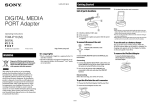
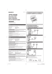
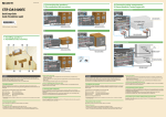
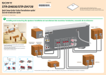
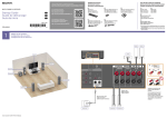
3-095-414-01(1) 3: Connecting other components/ 3: Raccordement d’autres éléments 2: Connecting the speakers/ 2: Raccordement des enceintes Video components/ Eléments vidéo SAT IN DIGITAL STR-DG810 DVD IN VIDEO 2/BD IN Blu-ray disc player*/ Lecteur de disques Satellite tuner or Set-top box/ DVD player/ TV/Téléviseur Blu-ray* Tuner satellite ou Décodeur Lecteur DVD AC OUTLET OUT ANTENNA (ASSIGNABLE) HDMI OPTICAL SAT IN Y AM XM PB/CB VIDEO 1 IN SAT IN PR/CR COAXIAL DVD IN VIDEO IN VIDEO OUT VIDEO IN VIDEO OUT IN AUDIO IN AUDIO IN AUDIO OUT AUDIO IN TV SAT DVD VIDEO 1 VIDEO IN SAT IN MONITOR DMPORT L L L DVD IN L VIDEO 1 IN MONITOR OUT DIGITAL SURROUND BACK L (ASSIGNABLE) R IN DVD IN VIDEO 2/BD IN AC OUTLET OUT ANTENNA HDMI OPTICAL COMPONENT VIDEO R L SAT IN Y AM XM L R PB/CB VIDEO 1 IN AUDIO OUT R OUT SA-CD/CD/CD-R PR/CR COAXIAL R R FRONT A SPEAKERS FRONT B SUB WOOFER R SURROUND DVD IN CENTER VIDEO IN VIDEO IN VIDEO OUT VIDEO IN VIDEO OUT SAT IN MONITOR DMPORT L L DVD IN L VIDEO 1 IN MONITOR OUT L SURROUND BACK COMPONENT VIDEO R L L L AUDIO OUT R R OUT R IN SA-CD/CD/CD-R R IN AUDIO IN AUDIO IN AUDIO OUT AUDIO IN TV SAT DVD VIDEO 1 R FRONT A SPEAKERS FRONT B SUB WOOFER R SURROUND CENTER L * Be sure to program the remote so that you can control the Blu-ray disc player. For details, refer to “Programming the remote” in the operating instructions supplied with the receiver. SURROUND BACK R Quick Setup Guide Guide d’installation L OUTPUT A R FRONT A SPEAKERS FRONT B A OUTPUT OUTPUT INPUT L R AUDIO CENTER SAT IN DIGITAL (ASSIGNABLE) DVD IN VIDEO 2/BD IN * Veillez à programmer la télécommande afin de pouvoir pour commander votre lecteur de disques Blu-ray. Reportez-vous à la section « Programmation de la télécommande » dans le mode d’emploi fourni avec l’ampli-tuner. AC OUTLET OUT ANTENNA HDMI OPTICAL SAT IN Y AM XM VIDEO 1 IN PB/CB COAXIAL PR/CR DVD IN VIDEO IN VIDEO OUT VIDEO IN VIDEO OUT IN AUDIO IN AUDIO IN AUDIO OUT AUDIO IN TV SAT DVD VIDEO 1 VIDEO IN MONITOR DMPORT L L L SAT IN DVD IN VIDEO 1 IN MONITOR OUT SURROUND BACK L L COMPONENT VIDEO R L L AUDIO OUT R OUT SAT IN DIGITAL (ASSIGNABLE) DVD IN VIDEO 2/BD IN SAT IN AC OUTLET OUT DIGITAL ANTENNA (ASSIGNABLE) HDMI OPTICAL SAT IN PB/CB VIDEO OUT VIDEO IN VIDEO OUT VIDEO IN SAT IN MONITOR L L DVD IN L SURROUND BACK R IN AUDIO IN AUDIO IN AUDIO OUT AUDIO IN SAT DVD VIDEO 1 SUB WOOFER FRONT B R FRONT A SPEAKERS R SURROUND VIDEO IN VIDEO OUT VIDEO IN VIDEO OUT MONITOR L L SAT IN DVD IN L VIDEO 1 IN MONITOR OUT L C CENTER SURROUND BACK COMPONENT VIDEO R L C C C L L AUDIO OUT R IN R PB/CB VIDEO IN DMPORT TV R PR/CR DVD IN AUDIO OUT R R OUT SA-CD/CD/CD-R R IN SA-CD/CD/CD-R XM VIDEO 1 IN L VIDEO 1 IN MONITOR OUT COMPONENT VIDEO R L L L AC OUTLET OUT Y AM COAXIAL PR/CR VIDEO IN DMPORT VIDEO 2/BD IN HDMI SAT IN XM VIDEO 1 IN COAXIAL DVD IN DVD IN ANTENNA OPTICAL Y AM R FRONT A SPEAKERS FRONT B SUB WOOFER R SURROUND R R OUT CENTER IN SA-CD/CD/CD-R R R IN AUDIO IN AUDIO IN AUDIO OUT AUDIO IN TV SAT DVD VIDEO 1 SUB WOOFER FRONT B R FRONT A SPEAKERS R SURROUND CENTER SURROUND BACK AUDIO OUT SAT IN DVD IN VIDEO 2/BD IN OUT LINE DIGITAL IN (ASSIGNABLE) ANTENNA CENTER SAT IN DIGITAL (ASSIGNABLE) DVD IN VIDEO 2/BD IN AC OUTLET OUT HDMI SAT IN Y AM XM PB/CB VIDEO 1 IN PR/CR COAXIAL DVD IN VIDEO IN VIDEO OUT VIDEO IN VIDEO OUT IN AUDIO IN AUDIO IN AUDIO OUT AUDIO IN TV SAT DVD VIDEO 1 VIDEO IN MONITOR DMPORT L L L SAT IN DVD IN VIDEO 1 IN MONITOR OUT L L SURROUND BACK COMPONENT VIDEO R L L AUDIO OUT R OUT R IN SA-CD/CD/CD-R R R SUB WOOFER FRONT B L R FRONT A SPEAKERS R SURROUND SUB WOOFER CENTER A B SURROUND BACK Y AM OUT B XM PB/CB VIDEO 1 IN PR/CR COAXIAL Cords used for connection (not supplied)/ Cordons utilisés pour le raccordement (non fourni) ANTENNA OPTICAL SAT IN A DVD IN VIDEO IN DMPORT Speaker cord/Cordons d’enceintes Monaural audio cord/Cordon audio mono L CENTER A VIDEO OUT VIDEO IN VIDEO OUT SAT IN L DVD IN VIDEO 1 IN MONITOR OUT COMPONENT VIDEO R L L L AUDIO OUT OUT R SURROUND VIDEO IN MONITOR R R Sony Corporation © 2007 Printed in Malaysia D HDMI OPTICAL IN SA-CD/CD/CD-R 10 mm (13/32") R R IN AUDIO IN AUDIO IN AUDIO OUT AUDIO IN TV SAT DVD VIDEO 1 SUB WOOFER FRONT B Cords used for connection (not supplied)/Cordons utilisés pour le raccordement (non fourni) C HDMI cable/Câble HDMI D Audio cord/Cordon audio 1: Installing speakers/ 1: Installation des enceintes English This Quick Setup Guide describes how to connect a DVD player, satellite tuner or set-top box, Blu-ray disc player, TV, speakers, and a sub woofer so that you can enjoy multi channel surround sound. Refer to the operating instructions supplied with the receiver for details. The illustrations in the guide designate speakers as through . Front speaker (left) Surround speaker (right) Front speaker (right) Surround back speaker Center speaker Sub woofer Surround speaker (left) About speaker jacks • Connect the jack to the jack of the receiver and connect the jack to the jack of the receiver. • Refer to the illustration above for details of connecting speaker cords. • Turn the locking knob until the speaker cord is connected. About the SPEAKERS (OFF/A/B/A+B) button You can select the speaker system. Refer to “6: Selecting the speaker system” in the operating instructions supplied with the receiver for details. 3: Connecting other components 1: Installing speakers The illustrations above show an example of a 6.1 channel speaker system (six speakers and one sub woofer) configuration. Refer to the operating instructions supplied with the receiver. 2: Connecting the speakers The illustration above shows how to connect the speakers. Connect the speakers according to the number and type of your speakers. About speaker cords • Use speaker cords, which are appropriate for the width of the room. • By deciding on the color or mark of the speaker cord to be connected to the plus (+) or minus (–) connector, you can always be sure of connecting the cord correctly without mistaking plus or minus. GBFR+DG810_2UC.indd 1 This is an example of how to connect this receiver and your components. Refer to step 3 of “Getting started” of the operating instructions supplied with this receiver for details on other connections and other components. Français Ce guide d’installation décrit comment raccorder un lecteur DVD, un tuner satellite ou un décodeur, un lecteur de disques Blu-ray, un téléviseur, des enceintes et un caisson de graves afin que vous puissiez bénéficier du son surround multicanal. Reportez-vous au mode d’emploi fourni avec l’ampli-tuner pour plus de détails. Les illustrations du guide désignent les différentes enceintes, de à . Enceinte avant Enceinte surround (gauche) (droite) Enceinte avant Enceinte surround (droite) arrière Enceinte centrale Caisson de graves Enceinte surround (gauche) 1: Installation des enceintes 4: Connect all power cords last Connect the AC power cord to a wall outlet. Refer to “Connecting the AC power cord (mains lead)” in the operating instructions supplied with the receiver. Les illustrations ci-dessus montrent un exemple de configuration d’un système à 6.1 canaux (six enceintes et un caisson de graves). Reportez-vous au mode d’emploi fourni avec l’ampli-tuner. 2: Raccordement des enceintes Les illustrations ci-dessus indique comment raccorder les eneintes. Raccordez les enceintes en fonction de leur nombre et de leur type. A propos des cordons d’enceintes • Utilisez des cordons d’enceintes adaptés à la largeur de la pièce. • En choisissant la couleur ou la marque du cordon d’enceinte à raccorder au connecteur plus (+) ou moins (–), vous êtes certain de toujours raccorder correctement le connecteur sans faire d’erreur sur les bornes plus ou moins. A propos des prises d’enceinte • Raccordez la prise à la prise de l’ampli-tuner et la prise à la prise de l’ampli-tuner. • Reportez-vous à l’illustration ci-dessus pour plus de détails sur le raccordement des cordons d’enceinte. • Tournez le bouton de verrouillage jusqu’à ce que le cordon d’enceinte soit correctement raccordé. A propos de la touche SPEAKERS (OFF/ A/B/A+B) Vous pouvez sélectionner le système d’enceinte. Reportezvous à la section « 6: Sélection du système d’enceintes » du mode d’emploi fourni avec l’ampli-tuner pour plus de détails. 3: Raccordement d’autres éléments Ce guide donne un exemple de raccordement de cet amplituner et de vos éléments. Reportez-vous à l’étape 3 de la section « Préparatifs » du mode d’emploi fourni avec cet ampli-tuner pour plus de détails sur le raccordement à d’autres éléments. 4: Raccordez tous les cordons d’alimentation en dernier lieu Raccordez le cordon d’alimentation secteur à la prise murale. Reportez-vous à la section « Raccordement du cordon d’alimentation secteur » dans le mode d’emploi fourni avec l’ampli-tuner. 1/18/2007 12:53:19 PM English Auto Calibration/Calibrage automatique ?/1 MASTER VOLUME TONE MODE TUNING MODE TONE TUNING DISPLAY INPUT MODE INPUT SELECTOR SPEAKERS (OFF/A/B/A+B) Setting up other components Optimizer microphone (supplied)/ Microphone optimiseur (fournie) You should set up each component so that the sound is output from the speakers correctly when you playback a connected component. The following case describes Sony components. Refer to the operating instructions supplied with each component. AUTO CAL MIC MEMORY/ ENTER CATEGORY MODE CATEGORY 2CH A.F.D. MOVIE MUSIC AUTO CAL DIRECT VIDEO 3 IN/PORTABLE AV IN PHONES VIDEO ?/1 L AUDIO R TV RM SET UP AV ?/1 ?/1 SYSTEM STANDBY VIDEO 1 VIDEO 2 VIDEO 3 DVD MASTER VOLUME TONE MODE DISPLAY TUNING MODE TONE TUNING Sony TV INPUT MODE SA-CD/CD TUNER SAT TV AUX DMPORT INPUT SELECTOR SPEAKERS (OFF/A/B/A+B) 2CH A.F.D. RECEIVER MOVIE 4 MUSIC Sony DVD player AUTO CAL MIC MEMORY/ ENTER CATEGORY MODE CATEGORY 2CH A.F.D. MOVIE MUSIC AUTO CAL DIRECT SLEEP VIDEO 3 IN/PORTABLE AV IN PHONES VIDEO 3 L AUDIO R CATEGORY MODE D. TUNING AUTO CAL 1 2 3 4 5 6 7 8 9 CLEAR 0/10 4 – /– – >10 GUIDE ENTER MEMORY DISPLAY V B 4 B v RETURN/ EXIT . MENU OPTIONS TOOLS – CATEGORY + REPLAY ADVANCE < < > Switch the input of the TV so that an image of the video component you selected is displayed on the TV. 1 2 3 4 5 Select “AUDIO SETUP” on the setup display of the DVD player. Set “AUDIO DRC” to “WIDE RANGE”. Set “DIGITAL OUT” to “ON”. Set “DOLBY DIGITAL” to “DOLBY DIGITAL”. Set “DTS” to “ON” or “DTS”. (Select the setting depending on the model) Note Set up the audio format of the playback disc to listen to multi channel sound. Sony Super Audio CD player Select a suitable playback area (multi channel or 2 channel). Sound may come out from only the front speaker L/R when 2 channel is selected. English Français Calibrating the speaker settings automatically Calibrage automatique des réglages des enceintes You can set up the speakers to obtain the sound you want from all connected speakers automatically by using the Auto Calibration function. The Auto Calibration function will: • Check the connection between each speaker and the receiver. • Adjust the speaker level. • Measure the distance of each speaker from your listening position. • Measure the speaker polarity. • Measure the speaker size. • Measure the frequency characteristics. Vous pouvez régler les enceintes afin d’obtenir automatiquement le son souhaité pour toutes les enceintes raccordées en utilisant la fonction Auto Calibration. La fonction Auto Calibration : • Vérifiez le raccordement entre chaque enceinte et l’ampli-tuner. • Ajustez le niveau des enceintes. • Mesure la distance entre chaque enceinte et votre position d’écoute. • Mesure la polarité des enceintes • Mesure la taille des enceintes • Mesure les caractéristiques de la fréquence 1 Connect the supplied optimizer microphone to the AUTO CAL MIC jack on the receiver. 1 Raccordez le microphone optimiseur fourni à la prise AUTO CAL MIC de l’ampli-tuner. Set up the optimizer microphone. 2 Réglez le microphone optimiseur. After the setting 2 Placez le microphone optimiseur au niveau de votre position d’écoute. Vous pouvez également utiliser une chaise ou un trépied pour que le microphone optimiseur se trouve au niveau de votre position d’écoute. Place the optimizer microphone at your listening position.You can also use a stool or tripod so that the optimizer microphone remains at the same height as your ears. 3 Press AUTO CAL. The Auto Calibration function starts. The measurement process will take approximately 30 seconds to complete. When the measurement ends, a beep sounds and “SAVE” appears on the display. 4 Press RECEIVER, then press to save the measurement results. You can also use MEMORY/ENTER on the receiver. For details on the measurement results, refer to “Confirming/saving the measurement results” of the operating instructions supplied with this receiver. Notes • If there are any obstacles in the path between the optimizer microphone and the speakers, the calibration cannot be performed correctly. Remove any obstacles from the measurement area to avoid measurement error. • During the calibration, the sound that comes out of the speakers is very loud. Pay attention to the presence of children or to the effect on your neighborhood. • Perform the Auto Calibration in a quiet environment to avoid the effect of noise and get a more accurate measurement. • The Auto Calibration function does not work in the following cases. - The ANALOG DIRECT function is selected. - The headphones are connected. GBFR+DG810_2UC.indd 2 3 Appuyez sur AUTO CAL. La fonction Auto Calibration démarre. L’exécution du processus de mesure prend environ 30 secondes. Une fois la mesure terminée, un bip retentit et « SAVE » apparaît sur l’écran. 4 Appuyez sur RECEIVER, puis sur la mesure. pour sauvegarder le résultat de Vous pouvez également utiliser MEMORY/ENTER sur l’ampli-tuner. Pour de plus amples informations sur les résultats de la mesure, reportez-vous à la section « Confirmation/sauvegarde des résultats de la mesure » du mode d’emploi fourni avec cet amplituner. Remarques • Si des obstacles se trouvent entre le microphone optimiseur et les enceintes, la calibration risque ne pas être effectuée correctement. Enlevez tous les obstacles se trouvant dans la zone de mesure, afin d’éviter toute erreur de mesure. • Pendant le calibrage, le son émis par les enceintes est très fort. Evitez la présence d’enfants et faites attention aux répercussions chez vos voisins. • Exécutez la fonction Auto Calibration dans un environnement tranquille pour éviter les parasites et obtenir une mesure plus précise. • La fonction Auto Calibration est inopérante dans les cas suivants : - lorsque la fonction ANALOG DIRECT est sélectionnée, - lorsque le casque est raccordé. The receiver is now ready to use. Refer to the operating instructions supplied with the receiver for details. Français Paramétrage d’autres composants Vous devez paramétrer chaque élément de sorte que le son soit émis correctement par les enceintes lorsque vous utilisez un composant raccordé. L’exemple suivant décrit des composants Sony. Reportezvous au mode d’emploi fourni avec chaque composant. Téléviseur Sony Commutez le signal d’entrée du téléviseur de sorte que l’image du composant vidéo sélectionné s’affiche sur le téléviseur. Lecteur DVD Sony 1 Sélectionnez « AUDIO SETUP » sur l’écran de configuration du lecteur DVD. 2 3 4 5 Réglez « AUDIO DRC » sur « WIDE RANGE ». Réglez « DIGITAL OUT » sur « ON ». Réglez « DOLBY DIGITAL » sur « DOLBY DIGITAL ». Réglez « DTS » sur « ON » ou « DTS ». (Sélectionnez le paramètre en fonction du modèle) Remarque Paramétrez le format audio du disque à lire pour entendre le son multicanaux. Lecteur CD Super Audio Sony Sélectionnez une plage de lecture adéquate (multicanaux ou deux canaux). Il est possible que le son soit émis par l’enceinte avant G/D uniquement lorsque l’option 2 canaux est sélectionnée. Après le paramétrage L’ampli-tuner est maintenant prêt à l’emploi. Reportez-vous au mode d’emploi fourni avec l’amplituner pour plus de détails. 1/18/2007 12:53:23 PM