1
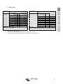
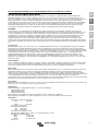
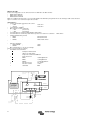
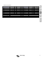
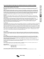
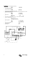
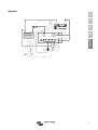
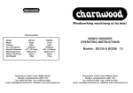
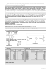
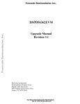
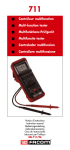
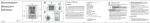
Manual EN Handleiding NL Manael FR Anleitung DE Appendix Battery Protect BP40/60/200 Copyrights 2008 Victron Energy B.V. All Rights Reserved This publication or parts thereof may not be reproduced in any form, by any method, for any purpose. For conditions of use and permission to use this manual for publication in other than the English language, contact Victron Energy B.V. VICTRON ENERGY B.V. MAKES NO WARRANTY, EITHER EXPRESSED OR IMPLIED, INCLUDING BUT NOT LIMITED TO ANY IMPLIED WARRANTIES OF MERCHANTABILITY OR FITNESS FOR A PARTICULAR PURPOSE, REGARDING THESE VICTRON ENERGY PRODUCTS AND MAKES SUCH VICTRON ENERGY PRODUCTS AVAILABLE SOLELY ON AN “AS IS” BASIS. IN NO EVENT SHALL VICTRON ENERGY B.V. BE LIABLE TO ANYONE FOR SPECIAL, COLLATERAL, INCIDENTAL, OR CONSEQUENTIAL DAMAGES IN CONNECTION WITH OR ARISING OUT OF PURCHASE OR USE OF THESE VICTRON ENERGY PRODUCTS. THE SOLE AND EXCLUSIVE LIABILITY TO VICTRON ENERGY B.V., REGARDLESS OF THE FORM OF ACTION, SHALL NOT EXCEED THE PURCHASE PRICE OF THE VICTRON ENERGY PRODUCTS DESCRIBED HERE IN. Victron Energy B.V. reserves the right to revise and improve its products as it sees fit. This publication describes the state of this product at the time of its publication and may not reflect the product at all times in the future EN Read the owners manual carefully before installing the BP! Owners manual BP40 / BP60 / BP200 NL The new Battery Protect BP40/60/200 (hereafter called BP) is an intelligent, waterproof, Battery Protect with accessory connections for a ON/OFF switch, Alarm buzzer or relay and our CurrentWatch current sensor (not included). The unit has two bolts as connection for the Input+ and the Output+ to guarantee low losses. Other connections, like the minus and the accessories, are made by a 4-pole 6.3mm faston connector. A blue LED shows the status (ON/OFF). In programmode it shows the program position. The BP has an 'Automatic system voltage Detection'; the BP detects which battery voltage (12 or 24V) is used. This does not need to be programmed manually. There is a choice of 10 on/off threshold voltages, for both 12V and 24V, which can be programmed in a simple way. The BP uses very little current. In the OFF mode or when in under voltage the BP uses just 2mA or less. FR DE Installation The installation of the BP has to be done by qualified personnel. Working with batteries is not without danger. Use wires of sufficient diameter and connectors of good quality. All connections have to be done via a fuse of the right value. See for a guiding principle for the wire diameter the separate chapter. Attention! Live wires should never make contact with the case of the BP or the vehicle. Wrong connection could damage the electronic circuit. Mount the BP on a cooling (metal) surface, so it can dissipate the generated heat. Mount it as close as possible to the battery (max. 50cm). This is the only way to exactly guard the voltage of the battery. Wait with connecting the equipment until the BP is fully programmed. Use a 1.5mm2 wire for the minus connection which is directly connected to the battery. No other equipment should be connected to this wire. Appendix Programming To start the program mode a connection should be made between the Input+ and the ProgramInput. The LED will start flashing. The number of flashes represents the program-position (see table) it is in. As soon as the desired programposition is reached the connection, between the Input+ and the ProgramInput, should be removed. To confirm the programmed position the LED will repeat the number of flashes. If it is not the right position, the previous steps have to be repeated. A change in position 11 or 12 has to be programmed separately by repeating the procedure and removing the connection after 11 or 12 flashes. The programmed positions will be remembered, even if the battery connection has been removed. After completing the programming the equipment can be connected. ATTENTION! First remove the battery-connection, connect the equipment to the Output+ and then reconnect the battery. Default program-position is position 1 and 11. See program table. Remote ON/OFF There is a possibility to connect a switch to the BP's OFF connection. If the OFF connection is connected to the Minus, the BP will shut down the connected equipment after about 1 second. If the connection is removed, the equipment will be started up again after about 1 second. The current through the switch is very low, so a small switch can be used. Alarm-output A buzzer can be connected to the alarm-output. The buzzer/alarm will be activated in case of under voltage after about 12 seconds. When there is no change in this situation the BP will shut down the equipment about 90 seconds later. The buzzer/alarm will also be stopped. Because at overvoltage (16V/32V) the equipment can be damaged, the BP will shut down the equipment immediately and the alarm-output will pulsate. This way you can hear the difference between an under voltage and an over voltage alarm. A second application of this output is with the use of a relay. In this application the BP should be programmed in program-position 12 (default is position 11) . This way the relay will be activated at alarm and when it reaches the upper voltage threshold it will be deactivated again. This way the relay can be used to activate a charger or generator. 1 CurrentWatch The Prog/Current connection can be used to connect a CurrentWatch. The CurrentWatch will show the current used by your equipment. If you are interested in this product, please contact your supplier. Wire cross section Use at least the following wire cross section for the bolt connection: • BP40 min 10mm2 • BP60 min 15mm2 • BP200 min 50mm2 In difficult environments it is advised to use larger cross sections. BatteryWatch (Optional) + FUSE Specifications: _ • Auto detect 12 or 24V Battery voltage + ◦ 8-20V -> 12V mode ◦ 20-35V -> 24V mode Input+ • 10 programmable voltage thresholds • Over voltage shut down ◦ > 16V (12V mode) ◦ > 32V (24V mode) • Current in use ~ 4mA + Sense • Current in OFF position or under- or over-voltage position ~ 2mA • Maximum Load (shut down current) Alarm Buzzer ◦ BP40 : ~ 40A (45A) ◦ BP60 : ~ 60A (65A) CurrentWatch _ ◦ BP200 : ~ 200A (210A) (Optional) • Peak current ◦ BP40 & BP60 : 120A ◦ BP200 : 480A • Shut down at overload after 5 sec. (after 1 minute start up) • Connections ◦ ON/OFF switch ◦ Alarm buzzer or relay ◦ CurrentWatch current sensor • Voltage drop ◦ BP40 : ~ 0,0875 @35A ◦ BP60 : ~ 0,125 @ 50A ◦ BP200 : ~ 0,1125 @ 180A • Voltage tolerance ~2% • Current output tolerance +/- 20% • Water proof IP66 • The BP will shut down after about 5 seconds when overloaded. After about 60 seconds the BP will start up again. 2 _ BG40/60 Output+ Output+ ON/OFF (Closed=OFF) BG200 Programming table EN 12 Volt mode 12 V 10 V 9,5V 11,25 V 11,5V 10,5V 11,5V 11,8 V 12 V 10 V Normal Alarm Relay function 11,5V 11,5V 13,25 V 13,8 V 12,8 V 12,8 V 12,8 V 13 V 13.2 V Position 1 Position 2 Position 3 Position 4 Position 5 Position 6 Position 7 Position 8 Position 9 Position 10 Position 11 Position 12 Uppervoltage Threshold 21 V 20 V 19 V 22,5 V 23 V 21 V 23 V 23,6 V 24 V 20 V Normal Alarm Relay function 24 V 23 V 23 V 26,5 V 27,6 V 25,6 V 25,6 V 25,6 V 26 V 26.4 V Position 1 & 11 Default positions Normal alarm: Alarm output activated at alarm; deactivated after 1 minute. Relay function: Alarm output activated at alarm; deactivated at overvoltage threshold. 3 Appendix 10,5V Undervoltage Threshold DE Uppervoltage Threshold FR Position 2 Position 3 Position 4 Position 5 Position 6 Position 7 Position 8 Position 9 Position 10 Position 11 Position 12 Undervoltage Threshold NL Position 1 24 Volt mode Lees de gebruiksaanwijzing eerst aandachtig door alvorens de BP aan te sluiten! Appendix Programmeren Om de programma modus op te starten moet er een verbinding gemaakt worden tussen de ProgramInput en de Input+. De LED zal gaan knipperen. Het aantal knipperingen geeft aan in welke programma-positie (zie tabel) de BP zich bevindt. Zodra de gewenste programma-positie bereikt is moet de verbinding (tussen de ProgramInput en de Input+) worden verbroken. Ter bevestiging zal de BP het aantal knipperingen herhalen door de procedure te herhalen en de verbinding te verbreken na 11 of 12 knipperingen. Indien het niet overeenkomt met uw keuze kunt u de stappen herhalen. Een eventuele programmering van positie 11 of 12 moet apart van de spanningsinstellingen gebeuren. Bij het loshalen van de accuspanning blijven de geprogrammeerde posities behouden. Als de programmering compleet is kan de apparatuur worden aangesloten. PAS OP! Haal hiervoor eerst de accu-aansluiting los, sluit de apparatuur aan op de Output+ en herstel daarna de verbinding met accu. Standaard programma-positie is positie 1 en 11. Zie verder programmeer tabel. DE Laat aansluiten over aan kundig personeel aangezien zich, tijdens het werken met accuspanning, gevaarlijke situaties kunnen voordoen! Gebruik voor het aansluiten van de BP bedrading van voldoende diameter en kabelschoenen van goede kwaliteit . Tevens moeten alle aansluitingen voorzien worden van een zekering van de juiste waarde! Zie voor leidraad kabeldiameter het hoofdstuk “kabeldiameter”. Pas op dat de spanningsvoerende delen nooit in aanraking komen met de behuizing van de BP! Bij het verkeerd aansluiten zal de elektronische schakeling beschadigen. Monteer de BP op een koelend (metalen) oppervlak zodat deze de ontwikkelde warmte af kan staan. Sluit de BP zo dicht mogelijk bij de accu aan (maximaal 50cm). Alleen op deze manier kan de spanning exact worden bewaakt. Wacht met het aansluiten van de apparatuur (gebruikers) totdat de BP is geprogrammeerd! Gebruik voor de minus aansluiting een kabel van 1,5mm2 welke direct van de accu naar de BP gaat. Gebruik deze aansluiting nergens anders voor. FR Installatie NL De nieuwe Battery Protect BP40/60/200 (hierna te noemen BP) is een intelligente, volledig waterdichte, batterij bewaker met uitbreidingsmogelijk-heden voor aan/uit schakelaar, alarm zoemer of relais. De unit is voorzien van twee bout aansluitingen, één Input+ en één Output+, om lage verliezen te waarborgen. Het overige, zoals de minus en de accessoires, worden aangesloten via een 4-polige 6,3mm faston connector. Een blauwe LED geeft de status (aan/uit) aan en in de programmeermodus geeft de LED de programmapositie aan. De BP is voorzien van 'Automatic system voltage detection' wat betekent dat de BG automatisch bepaalt wat de accuspanning (12V of 24V) van het systeem is. U hoeft deze dus niet handmatig in te stellen. Er is keuze uit een tiental aan/uit drempelspanning programma's voor zowel 12V als 24V welke op eenvoudige wijze geprogrammeerd kunnen worden. Het eigen stroomverbruik van de BP is minimaal. In de OFF mode of tijdens onderspanning is het verbruik minder dan 2mA! EN Gebruiksaanwijzing BP40 / BP60 / BP200 Remote ON/OFF U kunt op de OFF aansluiting van de BP een schakelaar aansluiten. Als de OFF aansluiting met de Minus verbonden wordt zal de BP na ca. 1 seconde de aangesloten apparatuur uitschakelen. Als de schakelaar weer wordt geopend zal de BP na ca. 1 seconde weer inschakelen. Aangezien de stroom door de schakelaar nihil is kan hiervoor een kleine schakelaar gebruik worden. Alarm-output Op de alarm-output kan een zoemer worden aangesloten welke bij onderspanning na ca. 12 seconden alarm geeft. Als de situatie niet veranderd zal de BP na ca. 90 seconden de aangesloten apparatuur uitschakelen, waarbij ook het alarm wordt uitgeschakeld. Aangezien er bij overspanning kans is op beschadiging van de aangesloten apparatuur zal bij overspanning (16/32V) deze direct worden uitgeschakeld en de alarm-output pulseren. Dit laatste zodat er onderscheid gemaakt kan worden tussen onderspanningsalarm en overspanningsalarm. Een tweede toepassing is het aansluiten van een relais op de alarm-output. Als dan de BP wordt geprogrammeerd in positie 12 dan zal het relais inschakelen bij alarm en pas weer uitschakelen bij het bereiken van de bovenspanning. Het relais kan op deze manier gebruikt worden voor het inschakelen van een lader of generator. CurrentWatch Op de Prog/Current aansluiting kan de, als accessoire te leveren, CurrentWatch worden aangesloten. Deze geeft de stroom, welke door de BP loopt , weer. Neem hiervoor contact op met uw leverancier. Kabeldiameter Gebruik minimaal de volgende diameter kabels voor de bout aansluitingen: BP40 minimaal 10mm2 ─ BP60 minimaal 15mm2 ─ BP200 minimaal 50mm2 Onder zwaardere omstandigheden wordt het aangeraden om grotere diameters te gebruiken. Bij overbelasting zal de BP na 5 seconden uitschakelen. Na ca. 60 seconden zal de BP zich weer inschakelen. ─ Specificaties: Autodetect 12 of 24V Accuspanning • 8-20V -> 12V mode • • 20-35V -> 24V mode 10 instelbare programma's Overspanning afschakeling • > 16V (12V mode) • > 32V (24V mode) Stroomopname in gebruik ca. 4mA Stroomopname in OFF positie of onder- of over-spanning positie ca. 2mA Maximum belasting/afschakelen • BP40 : ca. 40A / 45A • BP60 : ca. 60A / 65A • BP200 : ca. 200A / 210A Piekstroom • • • • • • • 1 _ BatteryWatch (Optional) BP40 & BP60 : 120A • BP200 : 480A Afschakelen bij overbelasting na 5 sec. (na 1 minuut weer aan) • • Aansluitmogelijkheden • AAN/UIT schakelaar • Alarm zoemer of relais • CurrentWatch stroomsensor • Spanningsval • BP40 : ca. 0,0875 @35A • BP60 : ca. 0,125 @ 50A • BP200 : ca. 0,1125 @ 180A • Spanningsnauwkeurigheid ca.2% • Stroom nauwkeurigheid +/-20% • Waterdicht IP66 + FUSE • _ + BG40/60 Input+ Output+ Output+ + BG200 ON/OFF Sense (Closed=OFF) Alarm Buzzer CurrentWatch (Optional) _ Programmeer tabel 12 Volt mode 24 Volt mode Onderspanning Bovenspanning Positie 1 10,5V 12 V Positie 2 10 V 11,5V Positie 3 9,5V 11,5V Positie 4 11,25 V 13,25 V Positie 5 11,5V 13,8 V Positie 6 10,5V 12,8 V Positie 7 11,5V 12,8 V Positie 8 11,8 V 12,8 V Positie 9 12 V 13 V 10 V Normale Alarmering Relais functie 13.2 V Positie 10 Positie 11 Positie 12 Onderspanning Bovenspanning Positie 1 21 V 24 V Positie 2 20 V 23 V Positie 3 19 V 23 V Positie 4 22,5 V 26,5 V Positie 5 23 V 27,6 V Positie 6 21 V 25,6 V Positie 7 23 V 25,6 V Positie 8 23,6 V 25,6 V Positie 9 24 V 26 V Positie 10 Positie 11 Positie 12 20 V 26.4 V Normale Alarmering Relais functie Position 1 & 11 Standaard instelling. Normaal alarm : Alarm uitgang wordt geactiveerd in geval van alarm; deactivatie na 1 minuut Relaisfunctie: Alarm uitgang wordt geactiveerd in geval van alarm; deactivatie bij het bereiken van de bovenspanning. 2 Lisez attentivement le mode d'emploi avant de raccorder le BP ! FR DE Appendix Installation Faites installer le BP par un spécialiste car travailler avec une batterie sous tension peut présenter certains dangers ! Pour le raccordement du BP, utilisez des câbles d'un diamètre suffisant et des cosses de bonne qualité. Tous les raccordements doivent également être équipés de fusibles de puissance appropriée ! Vous trouverez les directives pour le diamètre du câblage dans un chapitre à part. Veillez à ce que les éléments d'alimentation n'entrent jamais en contact avec le boîtier du BP ! Un mauvais raccordement endommagerait le circuit électronique. Montez le BP sur une surface (métallique) refroidissante qui pourra éliminer la chaleur produite. Raccordez le BP aussi près que possible de la batterie (50 cm max.). Ce n'est que de cette façon que la tension pourra être surveillée avec précision. Attendez d'avoir programmé le BP avant de raccorder l'appareil (utilisateurs) ! Pour le raccordement du négatif, utilisez un câble de 1,5 mm² qui reliera directement la batterie et le BP. N'utilisez ce raccordement qu'à cette seule et unique fin. NL Le nouveau Battery Protect BP40/60/200 (nommé ci-après BP) est un contrôleur de batterie intelligent et entièrement étanche, avec des possibilités d'extension pour un connecteur marche/arrêt, un vibreur ou un relais alarme et notre capteur de courant CurrentWatch (non fourni). L'unité est équipée de deux raccordements à écrous, un Input+ et un Output+ pour assurer de faibles pertes. Le reste, comme le négatif et les accessoires, est raccordé par une cosse quadripolaire de 6,3 mm. Un LED bleu indique le statut (marche/arrêt) et, en mode de programmation, la position du programme. Le BP est équipé d'une 'Automatic system voltage detection', ce qui signifie que le BP détermine automatiquement la tension (12V ou 24V) du système. Vous ne devez donc pas la régler manuellement. L'unité propose une dizaine de programmes de tension de seuil marche/arrêt pour le 12 V et pour le 24V, au réglage facile. La consommation individuelle du BP est minime. En mode Arrêt ou en sous-tension, l'appareil consomme moins de 2mA ! EN Mode d'emploi BP40 / BP60 / BP200 Programmation Pour lancer le mode de programmation, il faut établir une connexion entre le ProgramInput et l'Input+. Le LED se met à clignoter. Le nombre de clignotements indique la position du programme (cf. tableau) du BP. Dès que la position désirée est atteinte, la connexion (entre le Program-Input et l'Input+) doit être interrompue. Le BP réitérera le nombre de clignotements à titre de confirmation. Si ce nombre ne correspond pas à votre choix, vous pouvez répéter la séquence. Un changement de position sur 11 ou 12 doit être programmé séparément en répétant la procédure et en retirant la connexion après 11 ou 12 clignotements.. En cas de coupure de courant, les positions programmées sont conservées. Une fois la programmation terminée, l'appareil peut être raccordé. Attention ! Défaites d'abord le raccordement batterie, raccordez l'appareil à l'Output+ puis rétablissez le raccordement avec la batterie. Les positions standard des programmes sont 1 et 11. Cf. le tableau de programmation. Marche/arrêt à distance Vous pouvez raccorder un contacteur sur le raccordement OFF du BP. Si le raccordement OFF est relié au négatif, le BP déconnectera l'appareil raccordé après 1 seconde environ. Si le contacteur est rouvert, le BP se reconnectera après 1 seconde environ. Comme le courant dans le contacteur est nul, il est possible d'utiliser un petit contacteur. Sortie alarme La sortie alarme peut éventuellement être raccordée à un vibreur qui donne l'alerte après 12 secondes environ de sous-tension. Si la situation reste inchangée, le BP déconnectera l'appareil raccordé après 90 secondes et donc aussi l'alarme. Comme une surtension peut endommager l'appareil raccordé, ce dernier sera directement déconnecté en cas de surtension (16/32 V) et la sortie alarme sera sélectionnée. Ce pour pouvoir distinguer l'alarme de sous-tension et l'alarme de surtension. Il est également possible de raccorder un relais sur la sortie alarme. Si le BP est alors programmé sur la position 12, le relais se connectera en cas d'alarme et ne se déconnectera qu'une fois la surtension atteinte. Le relais peut donc être utilisé pour la connexion d'un chargeur ou d'un générateur. CurrentWatch L'accessoire CurrentWatch peut également être installé sur le raccordement Prog/Current. Il indique le courant qui passe par le BP. Prenez contact avec votre fournisseur pour de plus amples renseignements. 1 Diamètre du câble Pour les raccordements à écrous, utilisez au moins les diamètres de câble suivants : • BP40 10mm2 minimum • BP60 15mm2 minimum • BP200 50mm2 minimum Dans des conditions plus rigoureuses, il est conseillé d'utiliser des diamètres plus grands. En cas de surcharge, le BP se déconnectera après 5 secondes et se reconnectera après 60 secondes. Spécifications : Tension de la batterie autodectect 12 ou 24 V • 8-20V -> mode 12 V • 20-35V -> mode 24 V • 10 programmes réglables • Mise à l'arrêt en cas de surtension • > 16V (mode 12 V) • > 32V (mode 24 V) • Consommation de courant pendant utilisation 4mA environ • Consommation de courant en position Arrêt ou position sous-tension ou surtension • Charge maximale/mise à l'arrêt • BP40 : 40A / 45A environ • BP60 : 60A / 65A environ • BP200 : 200A / 210A environ • • Puissance maximale • BP40 & BP60 : 120A • BP200 : 480A • Mise à l'arrêt après 5 s en cas de surcharge (remise sous tension après 1 minute) • Possibilités de raccordement ◦ interrupteur marche/arrêt ◦ Vibreur ou relais alarme ◦ Capteur de courant CurrentWatch • Chute de tension ◦ BP40 :0,0875 @35A env. ◦ BP60 :0,125 @50A env. ◦ BP200 :0,1125 @180A env. • Précision tension 2% environ • Précision courant +/-20% • étanchéité IP66 • BatteryWatch (Optional) _ + FUSE _ + BG40/60 Input+ Output+ Output+ + ON/OFF Sense (Closed=OFF) Alarm Buzzer CurrentWatch (Optional) 2 _ BG200 2mA environ Tableau de programmation mode 24 volts sous-tension surtension 24 V 23 V 23 V 26,5 V 27,6 V 25,6 V 25,6 V 25,6 V 26 V 26.4 V FR DE 21 V 20 V 19 V 22,5 V 23 V 21 V 23 V 23,6 V 24 V 20 V Alarme normale Fonction relais surtension NL Position 1 10,5V 12 V Position 1 Position 2 10 V 11,5V Position 2 Position 3 9,5V 11,5V Position 3 Position 4 11,25 V 13,25 V Position 4 Position 5 11,5V 13,8 V Position 5 Position 6 10,5V 12,8 V Position 6 Position 7 11,5V 12,8 V Position 7 Position 8 11,8 V 12,8 V Position 8 Position 9 12 V 13 V Position 9 Position 10 10 V 13.2 V Position 10 Position 11 Alarme normale Position 11 Position 12 Fonction relais Position 12 Position 1 & 11 réglages standard Alarme normale : sortie alarme activée en cas d'alarme; désactivation après 1 minute. Fonction relais : sortie alarme activée en cas d'alarme; désactivation en cas de surtension. sous-tension EN mode 12 volts Appendix 3 Lesen Sie die Gebrauchsanweisung zuerst aufmerksam durch, bevor Sie den BP anschlieβen! FR DE Appendix Installation Überlassen Sie das Anschlieβen Fachpersonal, da bei der Arbeit mit Batteriespannung gefährliche Situationen entstehen können! Gebrauchen Sie zum Anschlieβen des BP nur Kabel mit einem ausreichenden Durchmesser und Kabelklemmen von guter Qualität. Auβerdem müssen alle Anschlüsse mit einer Sicherung mit korrektem Wert versehen sein! Siehe für Anleitung Kabeldurchmesser das separate Kapitel. Achten Sie darauf, dass spannungsführende Teile niemals mit dem BP-Gehäuse in Berührung kommen! Bei nicht korrektem Anschlieβen wird die elektronische Schaltung beschädigt. Montieren Sie den BP auf eine kühlende (Metall) Oberfläche, so dass diese die entwickelte Wärme abführen kann. Schlieβen Sie den BP so nah wie möglich an der Batterie an (maximal 50 cm). Nur auf diese Weise kann die Spannung exakt überwacht werden. Warten Sie mit dem Anschlieβen der Apparatur (Gebraucher), bis der BP programmiert ist! Gebrauchen Sie für den Minusanschluss ein Kabel von 1,5 mm2, das direkt von der Batterie zum BP geht. Gebrauchen Sie diesen Anschluss für keinen anderen Zweck. NL Der neue Battery Protect BP40/60/200 (im Folgenden BP genannt), ist ein intelligenter, vollständig wasserdichter Batterieüberwacher mit Erweiterungsmöglichkeiten für An/Aus Schalter, Alarmsummer oder Relais und unserem Current Watch Stromsensor (nicht mitgeliefert). Die Einheit ist mit zwei Schraubanschlüssen versehen, einem Input+ und einem Output+, um niedrige Verluste zu gewährleisten. Das Übrige, wie der Minuspol und das Zubehör werden über einen 4poligen, 6,3 mm Faston-Anschluss angeschlossen. Eine blaue LEDDiode gibt den Betriebszustand (an/aus) an und im Programmiermodus gibt die LED-Diode die Programmposition an. Der BP ist mit mit einer 'Automatic system voltage detection' versehen. Das bedeutet, dass der BP automatisch bestimmt, was die Batteriespannung des Systems ist (12V oder 24V). Diese brauchen Sie also nicht mit der Hand einzustellen. Es gibt eine Auswahl aus zehn An/Aus Schwellenspannungsprogrammen für sowohl 12V als auch 24V, die auf einfache Weise programmiert werden können. Der eigene Stromverbrauch des BP ist minimal. Im OFF Modus oder bei Unterspannung ist der Verbrauch niedriger als 2mA! EN Gebrauchsanweisung BP40 / BP60 / BP200 Programmieren Um den Programmmodus zu starten, muss zwischen dem ProgramInput und dem Input+ eine Verbindung hergestellt werden. Die LED-Diode wird dann blinken. Die Anzahl der Blinksignale gibt an, in welcher Programmposition sich (siehe Tabelle) der BP befindet. Sobald die gewünschte Programmposition erreicht ist, muss die Verbindung (zwischen ProgramInput und Input+) unterbrochen werden. Zur Bestätigung wird der BP die Anzahl Blinksignale wiederholen. Falls diese nicht mit Ihrer Wahl übereinstimmt, können Sie die Schritte wiederholen. Eine Änderung der Position 11 oder 12 wurde separate programmiert, indem das Verfahren wiederholt und die Verbindung nach 11 oder 12 Mal Blinken entfernt wurde. Beim Entfernen der Batterie-spannung bleiben die programmierten Positionen erhalten. Wenn die Programmierung abgeschlossen ist, kann die Apparatur angeschlossen werden. ACHTUNG! Machen Sie dazu zuerst den Batterieanschluss los, schlieβen Sie die Apparatur auf den Output+ an und stellen Sie danach die Verbindung mit der Batterie wieder her. Standardprogramm-Position ist Position 1 und 11. Ziehen Sie für weitere Einzelheiten die Programmiertabelle zurate. Remote ON/OFF Sie können an den OFF Anschluss des BP einen Schalter anschlieβen. Wenn der OFF Anschluss mit dem Minuspol verbunden wird, wird der BP nach ca. 1 Sekunde die angeschlossene Apparatur ausschalten. Wenn der Schalter wieder geöffnet wird, wird der BP nach ca. 1 Sekunde wieder einschalten. Da der Strom, der durch den Schalter flieβt, gleich null ist, kann hierfür ein kleiner Schalter gebraucht werden. Alarm-Output An den Alarm-Output kann ein Summer angeschlossen werden, der bei Unterspannung nach ca. 12 Sekunden einen Alarm abgibt. Wenn die Situation sich nicht ändert, wird der BG nach ca. 90 Sekunden die angeschlossene Apparatur ausschalten, wobei auch der Alarm ausgeschaltet wird. Da bei Überspannung die Gefahr von Beschädigung der angeschlossenen Apparatur besteht, wird diese bei Überspannung (16/32 V) direkt ausgeschaltet und wird der Alarm – Output pulsieren. Hierdurch kann Unterspannungsalarm von Überspannungsalarm unterschieden werden. Eine zweite Anwendung ist der Anschluss eines Relais an den Alarm-Output. Wenn dann der BP in Position 12 programmiert wird, wird das Relais bei Alarm einschalten und erst wieder ausschalten, wenn die Oberspannung erreicht wird. Auf diese Weise kann das Relais gebraucht werden, um ein Ladegerät oder einen Generator einzuschalten. CurrentWatch An den Prog/Current Anschluss kann, der als Zubehör lieferbare, CurrentWatch angeschlossen werden. Dieser gibt den Strom, der durch den BP läuft, wieder. Nehmen Sie dazu mit Ihrem Lieferanten Kontakt auf. Kabeldurchmesser Gebrauchen Sie minimal die folgenden Kabeldurchmesser für die Schraubanschlüsse: • BP40 minimal 10mm2 • BP60 minimal 15mm2 • BP200 minimal 50mm2 Unter schwereren Umständen wird wird empfohlen, gröβere Durchmesser zu gebrauchen. Bei Überbelastung wird sich der BP nach 5 Sekunden ausschalten. Nach ca. 60 Sekunden wird sich der BP wieder einschalten. 1 Spezifikationen: • Auto detect 12 oder 24V Batteriespannung • 8-20V -> 12V mode • 20-35V -> 24V mode • 10 einstellbare Programme • Überspannung Ausschaltung • > 16V (12V mode) • > 32V (24V mode) • Stromaufnahme während Gebrauch ca. 4mA • Stromaufnahme in OFF Position oder Unter- oder Überspannungsposition ca. 2mA • Maximum strom/ausschalten • BP40 :ca. 40A / 45A • BP60 :ca. 60A / 65A • BP200 :ca. 200A / 210A • Spitzenstrom • BP40 & BP60 : 120A • BP200 : 480A • Ausschalten bei Überbelastung nach 5 sec. (nach 1 Minute wieder an) • Anschlussmöglichkeiten • AN/AUS Schalter • Alarmsummer oder Relais • CurrentWatch Stromsensor • Spannungsabfall • BP40 :ca. 0,0875 @35A • BP60 :ca. 0,125 @ 50A • BP200 :ca. 0,1125 @ 180A • Spannungsgenauigkeit ca.2% • Stromgenauigkeit +/-20% • Wasserdicht IP66 BatteryWatch (Optional) _ + FUSE _ + BG40/60 Input+ Output+ Output+ + ON/OFF Sense (Closed=OFF) Alarm Buzzer CurrentWatch (Optional) 2 _ BG200 Programmiertabelle 24 Volt mode Position 1 Position 2 Position 3 Position 4 Position 5 Position 6 Position 7 Position 8 Position 9 Position 10 Position 11 Position 12 Normale Alarmierung: Alarmausgang aktiviert bei Alarm; deaktiviert nach 1 Minute Ober-spannung 24 V 23 V 23 V 26,5 V 27,6 V 25,6 V 25,6 V 25,6 V 26 V 26.4 V Appendix Position 1 & 11 ist Standardeinstellung. Unter-spannung 21 V 20 V 19 V 22,5 V 23 V 21 V 23 V 23,6 V 24 V 20 V normale Alarmierung Relaisfunktion DE Ober-spannung 12 V 11,5V 11,5V 13,25 V 13,8 V 12,8 V 12,8 V 12,8 V 13 V 13.2 V FR Unter-spannung 10,5V 10 V 9,5V 11,25 V 11,5V 10,5V 11,5V 11,8 V 12 V 10 V normale Alarmierung Relaisfunktion NL Position 1 Position 2 Position 3 Position 4 Position 5 Position 6 Position 7 Position 8 Position 9 Position 10 Position 11 Position 12 EN 12 Volt mode Relaisfunktion: Alarmausgang aktiviert bei Alarm; deaktiviert bei Erreichen der Oberspannung. 3 Appendix EN _ + NL BatteryWatch (Optional) FUSE FR _ + Input+ Output+ Output+ ON/OFF Sense BG200 Appendix + DE BG40/60 (Closed=OFF) Alarm Buzzer CurrentWatch (Optional) _ 1 2 Victron Energy Blue Power Distributor: Serial number: Version Date : 00 : 03 July 2012 Victron Energy B.V. De Paal 35 | 1351 JG Almere PO Box 50016 | 1305 AA Almere | The Netherlands General phone Customer support desk Fax : : : +31 (0)36 535 97 00 +31 (0)36 535 97 03 +31 (0)36 535 97 40 E-mail : [email protected] www.victronenergy.com