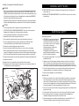
1
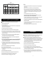
Technical Data
Model
Motor
Voltage
No Load Speed
Spindle Diameter
Wheel Diameter
Wheel Thickness
Net Weight
BG150
250w
240v
3450rpm
1/2” (12.7mm)
150mm (6”)
20mm
10kg
BG200
375w
240v
3450rpm
5/8” (15.8mm)
203mm (8”)
25mm
17kg
Charnwood, Cedar Court, Walker Road,
Bardon, Leicestershire LE67 1TU
Tel. 01530 516 926 Fax. 01530 516 929
email: [email protected] Website: www.charnwood.net
BENCH GRINDER
OPERATING INSTRUCTIONS
Models: BG150 & BG200
Charnwood, Cedar Court, Walker Road,
Bardon, Leicestershire LE67 1TU
Tel. 01530 516 926 Fax. 01530 516 929
email: [email protected] Website: www.charnwood.net
GENERAL SAFETY RULES
WARNING! READ AND UNDERSTAND ALL INSTRUCTIONS. Failure to follow all
instructions listed below may result in electric shock and/or serious personal injury.
NOTE: This stationary tool has been manufactured in accordance with the applicable
standard and equipment safety legislation. When using electrical appliances, it is important
to take safety precautions to avoid possible injury and damage. For that reason, you should
carefully read and store these instructions so that this information is available at all times.
SAVE THESE INSTRUCTIONS.
1. KEEP GUARDS IN PLACE and in working order.
2. REMOVE ADJUSTING KEYS AND WRENCHES. Form habit of checking to see that keys and
adjusting wrenches are removed from tool before turning it on.
3. KEEP WORK AREA CLEAN. Cluttered areas and benches invite accidents.
4. DON'T USE IN DANGEROUS ENVIRONMENT. Don't use power tools in damp or wet locations, or
expose them to rain. Keep work area well lighted.
5. KEEP CHILDREN AWAY. All visitors should be kept safe distance from work area.
6. MAKE WORKSHOP CHILD PROOF with padlocks, master switches, or by removing starter keys.
7. DON'T FORCE TOOL. It will do the job better and safer at the rate for which it was designed.
8. USE RIGHT TOOL. Don't force tool or attachment to do a job for which it was not designed.
9. USE PROPER EXTENSION CORD. Make sure your extension cord is in good condition. When
using an extension cord, be sure to use one heavy enough to carry the current your product
will draw. An undersized cord will cause a drop in line voltage resulting in loss of power and
overheating. Table 1, Minimum Gage for Power Cord shows the correct size to use depending
on cord length and nameplate ampere rating. If in doubt, use the next heavier gage. The
smaller the gage number, the heavier the cord.
10. WEAR PROPER APPAREL. Do not wear loose clothing, gloves, neckties, rings, bracelets, or other
jewelry which may get caught in moving parts. Non-slip footwear is recommended. Wear
protective hair covering to contain long hair.
11. ALWAYS USE SAFETY GLASSES. Also use face or dust mask if cutting operation is dusty.
Everyday eyeglasses only have impact resistant lenses, they are NOT safety glasses.
12. SECURE WORK. Use clamps or a vise to hold work when practical. It's safer than using your
hand and it frees both hands to operate tool.
13. DON'T OVERREACH. Keep proper footing and balance at all times.
14. MAINTAIN TOOLS WITH CARE. Keep tools sharp and clean for best and safest performance.
Follow instructions for lubricating and changing accessories.
15. DISCONNECT TOOLS before servicing; when changing accessories, such as blades, bits, cutters,
and the like.
16. REDUCE THE RISK OF UNINTENTIONAL STARTING. Make sure switch is in off position before
plugging in.
17. USE RECOMMENDED ACCESSORIES. Consult the owner's manual for recommended accessories.
The use of improper accessories may cause risk of injury to persons.
18. NEVER STAND ON TOOL. Serious injury could occur if the tool is tipped or if the cutting tool is
unintentionally contacted.
19. CHECK DAMAGED PARTS. Before further use of the tool, a guard or other part that is damaged
should be carefully checked to determine that it will operate properly and perform its intended
function - check for alignment of moving parts, binding of moving parts, breakage of parts,
mounting, and any other conditions that may affect its operation. A guard or other part that is
damaged should be properly repaired or replaced.
1
Light Bulb Replacement (Figure 9)
WARNING!
• Turn the power off and remove the plug from
the outlet before replacing light bulb.
FIGURE 9
Screws
Light Cover
• To reduce the risk of fire, use 10 watt,
12 volt light bulb only.
1. Remove screws from top of light bulb cover.
2. Remove light bulb cover.
3. Gently push in on bulb and rotate
counterclockwise to release.
Light Bulb
4. Insert new bulb into socket, push gently and
rotate clockwise to secure.
5. Replace light bulb cover and screws.
Bulb Socket
Light Bulb
ACCESSORIES
WARNING: RISK OF PERSONAL INJURY. Use only accessories that are recommended by
the manufacturer for your model. Accessories that may be suitable for one tool may become
hazardous when used on another tool.
Recommended Accessories:
Model: 60701240 6" diameter grinding, polishing or buffing wheels
Model: 60701250 8" diameter grinding, polishing or buffing wheels
10
Installing or Changing the Grinding Wheel (Figure 8)
GENERAL SAFETY RULES
WARNING!
• Turn the power off and remove the plug from the outlet before changing the grinding wheels.
When turning the grinder on with a newly installed wheel, DO NOT STAND IN FRONT OF THE
GRINDER. Stand to the side and allow the grinder to run for at least one minute before using it.
• Check grinding wheel frequently for wear or damage. Replace cracked wheels IMMEDIATELY.
Replace worn wheels before the diameter reaches 4".
20. DIRECTION OF FEED. Feed work into a blade or cutter against the direction of rotation of the
blade or cutter only.
21. NEVER LEAVE TOOL RUNNING UNATTENDED. Turn Power OFF. Don't leave tool until it comes to
a complete stop.
• Replacement grinding wheels must not exceed the maximum size on the grinder nameplate
and have a safe rated speed equal to or greater than the "No Load" speed on the nameplate.
CAUTION!
• Do not over tighten the wheel nut, because this may cause the wheel to crack.
• DO NOT INSTALL OR USE A DAMAGED GRINDING WHEEL. The force of rotation may cause a
damaged wheel to fly apart, and could injure operators or bystanders.
• Follow grinding wheel manufacturer's installation and use instructions.
ELECTRICAL SAFETY
1. Remove the tool rest knob, tool rest bracket and tool rest.
Grounding Instructions
2. Use a screwdriver to remove the wheel cover screws and remove the wheel cover.
1. (SEE FIGURE 1) In the event of a malfunction
or breakdown, grounding provides a path of
least resistance for electric current to reduce
the risk of electric shock. This tool is equipped
with an electric cord having an
equipment-grounding conductor and a
grounding plug. The plug must
be plugged into a matching outlet that is
properly installed and grounded in accordance
with all local codes and ordinances.
3. Loosen the grinding wheel nut using a hex or adjustable wrench. Rotate right wheel
nut counterclockwise to loosen. Rotate left wheel nut clockwise to loosen.
5. Remove nut, outer wheel flange, paper washers and wheel.
6. Inspect the new wheel carefully to ensure there are no cracks, chips or other damage.
7. Wipe the wheel flange surfaces clean, and install new grinding wheel in reverse order of
removal (including paper or fiber washers on both sides of wheel between wheel and flanges).
Note: Be sure the grinding wheel and outer flange are properly seated on the spindle shaft.
8. Tighten wheel retaining nut snug, without over-tightening. Over-tightening can damage wheel.
9. Replace the wheel cover.
10. Reposition the tool rest, spark deflector and eye shields to fit the new wheel.
11. Standing away from the rotational plane of the new wheel, turn on the grinder and allow it to
run at full speed for several minutes before use.
Figure 8
Hex Nut(s)
Lock Washer(s)
Grinding
Wheel Guard
Screw(s)
Lock Washer(s)
Spark Guard
Hex Nut(s)
3-Prong Plug
Grounding
Prong
Properly Grounded
3-Prong Outlet
2. Do not modify the plug provided - if it will not fit the outlet, have the proper outlet installed by
a qualified electrician.
3. Improper connection of the equipment-grounding conductor can result in a risk of electric
shock. The conductor with insulation having an outer surface that is green with or without
yellow stripes is the equipment-grounding conductor. If repair or replacement of the electric
cord or plug is necessary, do not connect the equipment-grounding conductor to a live terminal.
4. Check with a qualified electrician or service personnel if the grounding instructions are not
completely understood, or if in doubt as to whether the tool is properly grounded.
5. Repair or replace damaged or worn cord immediately.
Extension Cords
Grinding Wheel
Outer Flange
FIGURE 1
1. Make sure your extension cord is in good condition. When using an extension cord, be sure to
use one heavy enough to carry the current your product will draw. An undersized cord will
cause a drop in line voltage resulting in loss of power and overheating. Table 1 (page 3) shows
the correct size to use depending on cord length and nameplate Ampere rating. If in doubt, use
the next heavier gauge. The smaller the gauge number, the heavier the cord.
Spindle Shaft
Tool Rest Knob
Star Washer
Tool Rest
9
3. Do not abuse the cord. Never use the cord to carry the tools or pull the plug from the outlet.
4. Keep cord away from heat, oil, sharp edges or moving parts. Replace damaged cords
immediately. Damaged cords increase the risk of electrical shock.
Inner Flange
Wheel Nut
2. Use only 3-wire extension cords that have 3-prong grounding plugs and 3-pole receptacles that
accept the tool's plug.
Flat Washer
5. When operating a power tool outside, use an outdoor extension cord marked "W-A" or "W".
These cords are rated for outdoor use and reduce the risk of electrical shock.
2
Table 1.
Minimum Gage For Power Cord
Rating
Amp
Grinding
Total Length of cord in feet
Volts
25 ft.
50ft
18
16
14
14
16
16
14
12
100ft
150 ft
• Adjust the tool rest to accommodate large or unusually shaped workpieces.
AWG
1-5
6-10
11-12
12-16
120V
120V
120V
120V
• Allow grinder to reach full speed before contacting the work piece to the grinding wheel or
other accessory
16
14
14
12
14
12
Not Recommended
• Always keep the workpiece moving across the face of the grinding wheel. Grinding
continuously on the same spot on the wheel will cause grooves to be worn into the wheel.
The wheel may crack or become damaged more easily, and grinding of other objects will
be difficult.
• If the workpiece becomes hot, dip it into water or oil to cool it.
• Always grind on the face of the wheel (around the diameter), NEVER on the sides. Side
pressure on grinding wheels can cause cracking and damage.
• If the face of the grinding wheel is worn unevenly, becomes grooved, or is no longer smooth
and flat, the wheel should be reshaped with a dressing tool (not supplied).
SPECIFIC SAFETY RULES FOR GRINDERS
WARNING! For Your Own Safety Read Instruction Manual before Operating Grinder
1. Always use guards and eye shields.
• If the diameter of the grinding wheel is no longer round, the wheel should be reshaped with a
dressing tool or replaced.
• If the surface of the wheel becomes loaded and dull with workpiece material, the wheel
should be cleaned with a dressing tool.
• After reshaping, always readjust the tool rests and spark arrestors.
2. Do not over tighten wheel nut.
3. Adjust distance between wheel and work rest to maintain 1/16 inch or less separation as the
diameter of the wheel decreases with use.
4. Frequently clean grinding dust from beneath grinder.
5. Always keep hands and body away from grinding wheel at all times during operation.
6. Do not operate the tool in explosive atmospheres or in presence of flammable liquids or gases.
7. Do not operate grinder until it has been assembled and installed according to the "Assembly"
instructions of this manual.
8. Grinding wheels or other accessory must have a minimum speed (RPM) rating greater
than or equal to the "No Load" speed on the tool nameplate.
9. Inspect grinding wheel carefully for damage prior to use. Never use a damaged wheel.
Replace cracked wheel immediately.
10. Never use a grinding wheel larger or smaller than 6" in diameter for Model 2201994(60701240)
and 8" in diameter for Model 2201952 (60701250). Read and follow wheel manufacturer's
instructions for wheel mounting and use.
11. Grinding wheels can produce flying parks and other debris. Always wear eye protection,
protective clothing and make sure sparks are directed away from operator, others present or
flammable materials.
12. Never use the side of grinding wheel, use only the cutting edge.
13. Use only flanges furnished with the grinder.
14. Disconnect the power cord and wait for the wheel to come to a complete stop before making
any adjustments.
15. Always tighten adjustments knobs before use.
16. Keep arms, hands and fingers away from the grinding wheel to prevent severe cuts.
MAINTENANCE
WARNING: RISK OF PERSONAL INJURY. Always disconnect tool from power source
before making any adjustments, installing or changing accessories.
CAUTION: Tool service must be preformed only by qualified repair personnel. Service or
maintenance performed by unqualified personnel could result in a risk of injury. When servicing
a tool, use only identical replacement parts. Follow instructions in the Maintenance section of
this service manual. Use of unauthorized parts or failure to follow Maintenance Instructions
may create a risk of electrical shock or injury.
1. Clean the tool housing, grinding wheel and grinding wheel guards after each use.
2. Keep the tool dry, clean and free from oil and grease.
3. Store the tool on a safe and dry place, out of reach of children.
4. Do not use cleaning agents or solvents that could attach the plastic parts of the tool
5. Turn the tool off immediately and do not operate, until repaired, if tool begins to make abnormal
noise, vibrations, produces smoke or burning odor.
6. During normal use, grinding wheels can become grooved, rough, rounded at the edges or
loaded with grinding debris. Use a dressing tool (available at most hardware stores) to restore
the smooth flat surface of the wheel.
17. Always hold workpiece firmly when grinding. Use a clamp when practical.
18. Avoid kickback, always grind on the downward portion of the wheel.
3
8
CALIFORNIA PROPOSITION 65
OPERATION
WARNING!
• Never touch the grinding wheel while it is moving. Do not touch the work piece after grinding,
it will be very hot.
• Always wear ANSI compliant safety glasses at all times while operating the grinder.
WARNING: CHEMICAL HAZARD. Use of this tool may cause exposure to chemicals that are
known to the state of California to cause cancer, birth defects or other reproductive harm.
Dust and debris created during cutting, drilling, grinding or sanding on some materials may
contain chemicals known to the State of California to cause cancer or birth defects or other
reproductive harm. To reduce exposure to these chemicals, always use approved safety
equipment, work in a well-ventilated area and wear dusk mask that filters out
microscopic particles.
• Risk of personal injury - Never grind magnesium, magnesium alloy, wood or masonry wit
this machine.
CAUTION: Always make sure the tool rests, spark guards, eye shields and wheel retaining nuts
are properly adjusted securely tightened before operation.
GLOSSARY OF TERMS
Arbor - The shaft that the grinding wheel is mounted too.
This Bench Grinder is ideal for use in sharpening chisels, axes and other wood-cutting tools. It is
also useful for repairing tips on screwdrivers and drill bits or for removing excess metal burrs from
pieces of cut metal.
RPM - Number of revolutions that the wheel makes per minute of operation.
With the proper accessories, this tool can be used for cleaning metal surfaces using a wire brush
or for buffing and polishing using a cloth wheel.
Free Hand - Performing a grinding operation without using the tool rest, work clamp, vise, fixture,
etc, to keep the work piece secure during grinding.
ON/OFF Switch (Figure 6)
Kick-Back - Term used to describe the throwing of a workpiece from the grinding wheel. This is
usually caused by the work piece not being in contact with the tool rest or making unintentional
contact with wheel while unsupported.
Figure 6
The rocker ON/OFF power switch is located on
the front of the grinder.
Off
1. Press the side marked ON to turn the
grinder on.
Eye Shield - Transparent adjustable guard positioned between the grinding wheel and operator's
face during operation.
Tool Rest - Adjustable work surface used to support workpiece while grinding.
On
Workpiece - The item in which the grinding operation is being applied too.
2. Press the side marked OFF to turn the
grinder off.
SYMBOLS
The following symbols are used for this tool:
Symbol
HZ
RPM
V
Amp
Switch
~
Utility Tray (Figure 7)
Figure 7
Name
Hertz
Revolutions per minute
Volts
Amperes
Alternating Current
Designation/Explanation
Frequency (cycles per second)
Speed of grinding wheel
Voltage
Current
Type of current
FEATURES & SPECIFICATIONS
Use the built-in utility tray to store accessories
or maintenance items. Tray can also be filled
half way with coolant and used to cool
overheated workpieces.
Specifications:
Utility Tray
7
SKU:
Model Number:
Motor Type:
Voltage:
Motor Ratings:
Wheel Diameter:
Wheel Width:
Arbor Size:
No load Speed:
Wheel Grits:
Light Bulb:
2201994
60701240
Induction
120v~60Hz
1/3 HP (2.1Amp)
6" (150 mm)
3/4" (20 mm)
1/2" (12.7 mm)
3450 RPM
36 (Coarse), 60 (Medium)
10W, 12V
4
2201952
60701250
Induction
120v~60Hz
1/2HP (3.0Amp)
8" (200 mm)
1" (25 mm)
5/8" ( 15.88 mm)
3450 RPM
36 (Coarse), 60 (Medium)
10W, 12V
Installing Tool Rests (See Figure 3)
6" & 8" Bench Grinders
3X Magnifier
Eye Shield
Eye Shield
Eye Shield
Thumb Knobs
Figure 3
1. Unscrew and remove the carriage bolt from
the tool rest knob.
Tool Rest
Thumb Knob
2. Attach the tool rest bracket to the inside of the
wheel guard as shown. Note: position lower
slot in bracket over pin on wheel guard.
Tool Rest
Bracket
3. Attach tool rest to tool rest bracket with thumb
knob (large).
Note: V-groove tool rest mounts on left side.
Spark
Guard
Grinding
Wheel
Wheel
Guards
4. Adjust the distance between the wheel and
the tool rest to maintain 1/16 in. or less
separation as the diameter of the wheel
decreases with use.
Carriage
Bolt
Guide
Pin
Tool Rest
5. Tighten knob securely.
6. Repeat for the left tool rest.
Flat Washer
Star Washer
Tool Rest Knob
Adjustable
Tool Rest
Tool Rest
Knobs
Figure 4
Adjusting Spark Guards (Figure 4)
1. Loosen the upper wheel/spark guard screws.
Heavy-duty Steel Base
with Mounting Holes
2. Adjust the spark guards to within 1/16" of the
grinding wheel or other accessory being used.
On/Off Switch
Utility Tray
Spark Guard
Wheel/Spark Guard Screw
3. Tighten screws securely.
ASSEMBLY
WARNING! RISK OF PERSONAL INJURY. ALWAYS DISCONNECT THE TOOL FROM THE POWER
OUTLET BEFORE MAKING ANY ADJUSTMENT, INSTALLING OR CHANGING GRINDING WHEELS.
CAUTION: The grinder must be assembled and adjusted before use. DO NOT plug unit into
power source until the unit has been completely assembled and adjusted.
Mounting the Grinder to the Workbench
Before attempting to use this grinder, it must
be properly mounted to a workbench or
grinding stand. (See Figure 2)
CAUTION: Bench grinders vibrate. Grinder
movement during high-speed rotation may
cause injury or damage to the workpiece or
operator. Mount the grinder securely to a
sturdy workbench or grinding stand.
1. Position the grinder on the workbench.
2. Mark the workbench through the four
mounting holes located in the grinder base.
3. Drill holes in the workbench at the marks.
4. Using four long bolts, washers, lock-washers
and nuts, as shown (not supplied), secure the
grinder to the workbench.
Thumb Knob
Flat Washer
Lock Washer
Installing Eye Shields (Figure 5)
Figure 2
Figure 5
Eye shields must be installed before operating
the bench grinder.
1. Mount the left and right shield brackets to the
inside of the wheel guards as shown.
Bolt
Flat
Washer
Flat
Washer
Lock
Washer
Hex Nut
5
2. Attach the left and right eye shields to the
shield brackets with thumb knobs (small).
Note: 3X magnifying eye shield mounts to
left side.
Shield Bracket
Thumb Knob
Eye Shield
3. Adjust the eye shield so that it is between the
operatorís eyes and the grinding wheel or
other accessory.
4. Tighten eye shield thumb knobs securely.
6