1
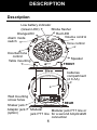
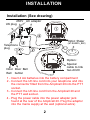
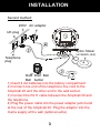
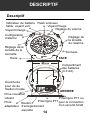
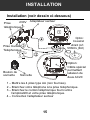
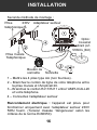
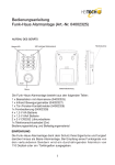
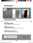
0
DESCRIPTION
Description
Low battery indicator
(Green LED)
Strobe flasher
Red LED
OrangeLED
Volume control
Alarm mode
switch
Tone control
Doorbell tone
control
Table mounting
Speaker
FRONT
batteries
compartment
(4 X AA)
Wall mounting
screw holes
Shaker jack
Adaptor jack
(option)
REAR
Modular
Modular jack PTT line or
jack PTT line for a second Amplicall20
connection
1
INSTALLATION
Installation (See drawing)
230V AC adaptor
UK plug
Option: Shaker
(ref.:SHAKCL_BLK)
Telephone
plug
Option :
Special
cable to link
two AC20
Door Door Bell
Bell button
1 - Insert 4 AA batteries into the battery compartment
2 - Connect the UK line cord into your telephone and into
the connector fitted from the Amplicall 20 into the PTT
socket.
3 - Connect the UK line cord from the Amplicall 20 and
the PTT wall socket.
4 - Plug the power cable into the power adapter jack
found at the rear of the Amplicall 20. Plug the adaptor
into the mains supply at the wall (optional extra)
2
INSTALLATION
Second method:
230V AC adaptor
UK plug
Option: Shaker
(ref.:SHAKCL_BLK)
Telephone
plug
Door Door Bell
Bell button
1) Insert 4 AA batteries into the battery compartment
2) Connect one end of the telephone line cord to the
Amplicall 20 and the other end to the wall socket.
3) Connect the RJ11 cable between the Amplicall 20 and
the telephone.
4) Plug the power cable into the power adapter jack found
at the rear of the Amplicall 20. Plug the adaptor into the
mains supply at the wall (optional extra)
3
INSTALLATION
Electrical connection : The apparatus is designed to
operate from a 230V 50Hz supply only. (Classified as
«hazardous voltage» according to EN60950 standard).
The apparatus does not incorporate an integral power
on/off switch. To disconnect the power, either switch off
supply at the mains power socket or unplug the AC
adaptor. When installing the apparatus, ensure that the
mains power socket is readily accessible.
Telephone connection : Voltages present on the
telecommunication network are classified TNV-3
(Telecommunication Network Voltage) according to the
EN60950 standard.
4
INSTALLATION
Setting up Door bell
1. The door bell can be used by people who need
assistance.
2. The door bell can be fixed on a wall or a door
surround. Drill two holes horizontally, 15mm apart
and place the supplied anchors into the two holes.
Hang the door bell onto the two anchors and then
insert and tighten the screws. Stick the
EMERGENCY CALL sticker over the two holes.
3. The door bell can be stuck onto a door or window
using the supplied strong adhesive tape. Remove the
protective paper from the adhesive tape on the back
of the door bell and stick to the required door or
window.
Wall Mounting
1. Drill two holes horizontally, 96mm apart, and leave the
screws protruding from the wall by 5mm.
2. Hang the base on to the two screws and pull the base
down to lock it on
5
INSTALLATION
Table Mounting
If you want to mount the unit on a table, simply place it in
the base cradle and place the base cradle on a table.
Setting the Alarm Mode
Choose which alarm mode you want by moving the alarm
mode switch to one of the following positions:
0
:no alarm
:both strobe flasher and sound alarm activated
:both strobe flasher and shaker (if connected)
activated
:both sound alarm and shaker (if connected)
activated
Volume Control Slide Switch
Use the slider control to adjust the volume of the door bell
ring, phone ring or power OFF
Tone Control Switch (3 Positions)
Set the tone of the alarm sound.
Door Bell Tone Control
The three position switch allows you to set a different
tone when the door bell rings.
6
INSTALLATION
Change The Battery of Indoor unit (option)
The unit requires 4×AA batteries
1. Open the battery compartment door.
2. Insert 4 x AA batteries into the battery compartment.
3. Snap the battery compartment door back into place.
Note: when the red LED indicator flashes, it is time to
replace the batteries.
Whilst replacing the batteries, disconnect all telephone
line cords from the modular wall jacks.
Second Amplicall 20
Another Amplicall 20 can be added to the system (call
01707 384483)
Change the Battery of the Door bell
The door bell is supplied with a 23A 12V battery. The
Door bell is supplied ready to use, it is not necessary to
open the Door Bell when you first install the Amplicall 20.
To replace the battery, unscrew the door bell from the
wall, unscrew the five screws located on the base and
open the box to get access to the battery compartment.
Replace the battery, replace back and remount.
7
INSTALLATION
Note: Do not use a rechargeable battery. Do not put the
used battery into the household rubbish, pay attention to
battery regulations regarding battery disposal.
The Pairing Procedure
1. Press and hold the Pairing/Test button until the unit
makes a beep sound, then release the Pairing/Test
st
button. The 1 LED lights to indicate that the
pairing mode has been entered.
2. Press and hold the Pairing/Test button again until the
st
1 LED flashes, then press and hold the remote
button at the same time until the strobe flasher
flashes. The unit makes a beep sound to confirm
pairing has been successful.
nd
rd
3. If the user wants to pair a 2 and 3 remote, when
st
the 1 LED lights, press the Pairing/Test button once,
st
nd
the 1 LED goes off and then the 2 LED lights.
nd
The user is then able to pair the 2 remote. Repeat
rd
the same procedure for the 3 remote.
4. Repeat the above, all 3 LEDS flashing together for
th
the 4 remote pairing.
8
INSTALLATION
Un- Register The Pairing:
1. Press and hold the Pairing/Test button for 5 seconds
to enter un-register mode, 3 LEDs flash together.
st
2. If user wants to un-register the 1 door bell, press the
st
Pairing/Test button once, the 1 LED will be flashing
(the other 2 LED light), then press and hold the
st
Pairing/Test button until the 1 LED goes off, beeps
st
to confirm. The 1 door bell is now un-registered.
st
3. If user wants to keep the 1 door bell but un-register
nd
rd
st
the 2 or3 door bell, when the 1 LED flashes,
nd
press the Pairing/Test button again, the 2 LED
flashes (other 2 LED light) to select which door bell to
be un-registered.
4. Repeat the above, all 3 LEDS flashing together for
th
the 4 door bell unregister.
To check whether the unit works normally, you can press
the Door bell button, the unit would sound alarm and flash.
Operation
Once the indoor unit and the door bell have been placed
in the required locations and all required batteries have
been inserted, you are ready to use the device.
To use the device as a door bell, the person who needs
assistance must press the Door Bell button. The indoor
unit will sound an alarm and flash (depending on the
Alarm mode setting).
To use the device as a telephone ringer amplifier whilst
receiving a new call, the indoor unit will sound an alarm
and flash (depending on the Alarm mode setting)
9
INSTALLATION
Trouble shooting
Symptom
No incoming call yet
the Amplicall20 rings
automatically or
rings continuously.
The shaker vibrates
automatically or
continuously.
The strobe LED
flashes automatically
or continuously.
The red low battery
LED flashes
automatically.
When there is an
incoming call but no
ringing can be heard.
Solution
1) Check the batteries are
inserted correctly.
2) Check the power adaptor is
connected correctly.
3) Turn off the power for 10
minutes and then turn it
back on.
1) Replace the batteries.
2) Turn off the power for 10
minutes and then turn it
back on.
1) Check it is connected to the
power adaptor correctly.
2) Check the batteries are
inserted correctly.
3) Check the volume switch is
on.
4) Check it is connected to the
line cord correctly.
5) Check the alarm mode
selection switch position is
correct
10
INSTALLATION
When there is an
incoming call but the
shaker doesn‟t
vibrate.
The Amplicall20
does not ring when
the doorbell is
pressed
1) Check it is connected to the
shaker correctly.
2) Check the shaker socket to
see if it has been damaged.
3) Check the alarm mode
selection switch position is
correct.
1) Check that the red light on
the doorbell flashes when it
is pressed. If it does not,
change the battery.
2) Register the doorbell to the
AmpliCALL20 again
3) Check the alarm mode
selection switch position is
correct i.e. not on „0‟
11
GUARANTEE
From the moment your Geemarc product is purchased,
Geemarc guarantee it for the period of one year. During
this time, all repairs or replacements (at our option) are
free of charge. Should you experience a problem then
contact our helpline or visit our website at
www.geemarc.com. The guarantee does not cover
accidents, negligence or breakages to any parts. The
product must not be tampered with or taken apart by
anyone who is not an authorised Geemarc
representative.The Geemarc guarantee in no way limits
your legal rights.
IMPORTANT: YOUR RECEIPT IS PART OF YOUR
GUARANTEE AND MUST BE RETAINED AND
PRODUCEDIN THE EVENT OF A WARRANTY CLAIM
Please note : The guarantee applies to the United
Kingdom only.
Declaration : Hereby Geemarc Telecom SA declares
that this product is in compliance with the essential
requirements and other relevant provisions of the Radio
and Telecommunications Terminal Equipment Directive
1999/5/EEC and in particular article 3 section 1a, 1b and
section 3.
The declaration of conformity may be consulted at
www.geemarc.com
12
GUARANTEE
Recycling directives : The WEEE (Waste Electrical and
Electronic Equipment) has been put in place for the
products at the end of their useful life are recycled in the
best way.When this product is finished with, please do
not put it in your domestic waste bin.Please use one of
the following disposal options:
- Remove the batteries and deposit them in an
appropriate WEEE skip. Deposit the product in an
appropriate WEEE skip.
- Or, hand the old product to the retailer. If you purchase
a new one, they should accept it. Thus if you respect
these instructions you ensure human health and
environmental protection.
For product support and help visit our website
at www.geemarc.com
Telephone 01707 384438
Or fax 01707 832529
13
DESCRIPTIF
Descriptif
Indicateur de batterie Flash lumineux
faible, voyant vert
Voyant Rouge
Réglage du volume
Voyant Orange
Configuration
d‟alarme
Réglage de
la tonalité
de l‟alarme
Réglage de la
tonalité de la
sonnette
Socle
Sonnerie
FACE
Compartiment
des batteries
(4 X AA)
Ouvertures
pour vis de
fixation murale
ARRIERE
Prise coussinet
vibrant
Prise ligne PTT ou
Prise ligne PTT pour la connection
Prise
Bouton
d‟un second AC20
adaptateur d‟enregistrement
sonnette
14
INSTALLATION
Installation (voir dessin ci-dessous)
230V
Prise
téléphonique
Adaptateur secteur
Option :
Coussinet
vibrant (ref.:
SHAKCL_BLK)
Prise murale
Téléphonique
Option:
Câble spécial
permettant
laliaison de
deux AC20
Bouton de
sonnette
Sonnette
1 – Mettre les 4 piles type AA (non fournies).
2 – Branchez votre téléphone à la prise téléphonique.
3 – Branchez le cordon téléphonique fourni entre
l‟amplicall20 et votre prise téléphonique.
4 – Connectez l‟adaptateur secteur
15
INSTALLATION
Seconde méthode de montage :
230V
Prise
téléphonique
Adaptateur secteur
Option :
Coussinet
vibrant (ref.:
SHAKCL_BLK)
Prise murale
Téléphonique
Bouton de
sonnette
Sonnette
1 – Mettre les 4 piles type AA (non fournies) .
2 – Branchez le cordon de ligne de votre téléphone entre
la prise murale et l‟Amplicall 20.
3 – Branchez le cordon RJ11/RJ11 entre l‟AMPLICALL20
et votre téléphone.
4 – Connectez l‟adaptateur secteur
Raccordement électrique : l‟appareil est prévu pour
fonctionner uniquement avec l‟adaptateur secteur 230V
50Hz fourni. (Tension classée “dangereuse” selon les
critères de la norme En60950).
16
INSTALLATION
Par précaution en cas de danger, le bloc alimentation
secteur sert de dispositif de sectionnement de
l‟alimentation 230V. Il doit être installé à proximité du
matériel et être aisément accessible.
Raccordement téléphonique : les tensions présentes
sur ce réseau sont classées TRT-3 (Tension de Réseau
de Télécommunication) au sens de la norme EN60950.
Montage mural de la sonnette
1. La sonnette peut être portée par la personne
nécéssitant de l‟aide
2. Vous pouvez fixer la sonnette sur un mur ou sur une
porte. Percez 2 trous horizontallements espacés de
14 mm. Mettez les 2 chevilles fournies et fixez votre
sonnette avec les 2 vis, puis collez l‟autocollant blanc
fourni sur les 2 trous.
3. Vous pouvez coller la sonnette sur une porte ou sur
une fenêtre en utilisant le ruban adhésif. Retirez le
papier protecteur du ruban adhésif sur le dos de la
sonnette et placez-la à l‟endroit requis
17
INSTALLATION
Configuration De L’Alarme
Sélectionnez l‟alarme par le commutateur 4 positions:
0
: aucune alarme sélectionnée
: flash lumineux et sonnerie électronique activés
: flash lumineux et coussinet vibrant (si connecté)
activés
: sonnerie électronique et coussinet vibrant (si
connecté) activés
Potentiomètre De Volume
Utilisez le potentiomètre de volume pour ajuster le
volume de sonnerie de la porte, du téléphone ou éteindre
la sonnerie complètement.
Interrupteur De Tonalite (3 Positions)
Vous pouvez choisir entre 3 tonalités d'alarme
Réglage de la tonalité de la sonnette
Vous avez le choix entre 3 positions différentes pour la
tonalité de sonnerie pour la sonnette.
18
INSTALLATION
Montage Mural
Percez 2 trous à l'horizontale distant de 96 mm dans
votre mur. Insérez 2 chevilles avec leurs vis. Laissez
dépasser les vis de 5 mm.
Faites glisser votre base dans les têtes de vis.
Placez ensuite l'AMPLICALL20 sur les vis et tirez la base
vers le bas afin que le boîtier soit bloqué.
Table De Montage
Si vous souhaitez installer l'AMPLICALL20 sur une table,
posez le socle, puis insérez le boitier dedans.
Remplacement Des Piles
Votre appareil utilise 4 piles AA.
1. Ouvrez le compartiment des piles.
2. Insérez les 4 piles type AA
3. Refermez le couvercle du compartiment des piles.
Note: Si le voyant du niveau des piles est rouge, vous
devez les remplacer.
Lors de tout changement, débranchez le cordon de ligne
de votre base.
Remplacement de la pile pour la Sonnette
La sonnette utilise une pile 23A 12V . La sonnette est
livrée prête à l‟emploi avec sa pile, cela n‟est pas
nécessaire d‟en mettre une.
19
INSTALLATION
Pour remplacer la pile, retirer la sonnette du mur, retirer
les 5 vices situées à l arrière et ouvrir le boitier pour avoir
accés à la pile. Remplacer la pile,refermer le boitier et le
replacer au mur.
Note: Ne pas utiliser de pile rechargeable. Ne pas mettre
la pile à la poubelle, utiliser les lieux de collecte approprié
pour pile pour vous en débarasser.
Enregistrement d’une sonnette
supplémentaire
1.Appuyez et maintenez le bouton enregistrement
sonnette pendant 2 secondes jusqu‟à ce que vous
entendez un bip sonore de confirmation.
2.La première LED orange s‟allume. Appuyez en même
temps sur le bouton enregistrement sonnette et sur
celui de votre sonnette additionnelle. Un flash et un bip
sonore seront envoyés par la base pour la confirmation
d‟enregistrement.
3.Si vous souhaitez ajouter une deuxième ou une
troisième sonnette, reprenez le paragraphe 1. Lorsque
le voyant orange s‟allume, appuyez sur le bouton
20
INSTALLATION
enregistrement de la base pour passer au deuxième
voyant vert.Reprenez le paragraphe 3 pour enregistrer
une troisième sonnette sur le voyant rouge.
4.Reprenez le paragraphe 3 pour enregistrer une
quatrième sonnette. Les 3 voyants seront allumés en
même temps.
Supprimer une sonnette
1.Appuyez et maintenez le bouton enregistrement
sonnette pendant 5 secondes jusqu‟à ce que les 3
voyants clignotent.
2.si vous voulez supprimer la première sonnette,
appuyez sur le bouton enregistrement sonnette afin
que le voyant orange clignote. Restez appuyer sur le
bouton enregistrement sonnette jusqu‟à ce que les
voyants s‟éteignent. Votre sonnette est supprimée.
3.Si vous souhaitez supprimer la 2ème ou la 3ème
sonnette, reprenez le paragraphe 1 et 2. Lorsque le
voyant orange clignote, appuyez sur le bouton
enregistrement sonnette afin de modifier la couleur du
voyant à supprimer. Restez appuyer sur le bouton
enregistrement sonnette jusqu‟à ce que les voyants
s‟éteignent . Votre sonnette est supprimée.
Appuyez sur le bouton de la sonnette pour vérifier la
suppression.
21
INSTALLATION
Symptôme
L‟Amplicall20, le
coussinet vibrant ou le
flash lumineux
s‟enclenche
automatiquement sans
que le téléphone sonne.
L‟indicateur de batterie
faible clignote rouge
alors que l‟Amplicall20
est connecté à
l‟adaptateur secteur
L‟Amplicall20 ne sonne
pas alors qu‟il est
connecté à l‟adaptateur
secteur et que les 4
batteries sont insérées.
L‟Amplicall20 est bien
connecté à l‟adaptateur
secteur ou les piles sont
bien insérées. Il sonne
ou flash lorsque le
téléphone sonne mais
le coussinet vibrant ne
fonctionne pas.
Solution
1) Vérifiez que les batteries
soient bien insérées.
2) Vérifiez que l‟adapteur
secteur soit bien
connecté.
3) Eteignez l‟Amplicall20
pendant 10 minutes et
rallumez-le.
1) Vérifiez l‟état de la
batterie.
2) Eteignez l‟Amplicall20
pendant 10 minutes et
rallumez-le.
1) Vérifiez que le coussinet
vibrant soit bien
connecté.
2) Vérifiez que la prise du
coussinet vibrant ne soit
pas endommagée.
3) Vérifiez que vous avez
choisi la bonne
configuration d‟alarme.
22
INSTALLATION
L‟Amplicall20 ne sonne
pas lors d‟un appui sur
le bouton de sonnette
1) Vérifiez que le voyant
s‟allume lors d‟un appui.
Sinon changer la pile.
2) Refaire la procédure
d‟enregistrement
sonnette
3) Contrôler que le bouton
configuration d‟alarme ne
soit pas sur la position 0
et le bouton volume sur
Off.
23
GARANTIE
Cet appareil est garanti 1 an pièces et main-d'oeuvre. La
date d'achat figurant sur le ticket de caisse fera foi. Cette
garantie s'exerce sous réserve d'une utilisation normale
de l'appareil. Les dommages occasionnés par les
surtensions électriques, la foudre ou par un choc sur
l'appareil ne peuvent en aucun cas être couverts par la
garantie. En cas de problème fonctionnel et avant de
nous retourner votre appareil, contactez notre service
après vente de : 8h30 à 12h30 et de 14h00 à 17h00 du
Lundi au Jeudi et de 8h30 à 12h30 et de 14h00 à 16h30
le Vendredi.
DECLARATION : Ce produit respecte les exigences de
compatibilité électro-magnétique et de sécurité électrique
demandées par la directive européenne RTTE.
Par ailleurs, il est compatible avec les différents réseaux
téléphoniques européens (normes TBR21/37/38).
Directives de recyclage: La directive DEEE (Déchet
d‟Equipement Electrique et Electronique) a été mise en
place dans le but d‟assurer la collecte sélective en vue
de la valorisation, réutilisation ou recyclage des produits
en fin de vie. Lorsque votre produit ne fonctionne plus, ne
le jeter pas dans votre poubelle ménagère. Suivez l‟une
des procédures décrite ci-dessous:
La déclaration de conformité peut être consultée
sur le site : www.geemarc.com
24
GARANTIE
- Déposez les piles et votre ancien appareil dans un lieu
de collecte approprié.
- Rapportez votre ancien appareil chez le distributeur qui
vous vendra le nouveau. Il devra l‟accepter.
Ainsi, si vous respectez ces instructions vous faites un
geste pour l‟environnement et vous contribuez à la
préservation des ressources naturelles et à la protection
de la santé humaine.
Consultez notre site internet pour obtenir des
informations et de
l'aide sur nos produits : www.geemarc.com
Vous pouvez nous contacter
par téléphone 03 28 58 75 99
ou par fax 03 28 58 75 76
25
BESCHREIBUNG
Beschreibung
Niedrige Batterieanzeige Blinklicht
Orange LED
Rote LED
Lautstärkeregel
Schalter
ung
Alarmmodus
Tonregelung
Türklingelton
Einstellung
Tischbefestigung
Akustisches
Signal
VORDERSEITE
Batteriefach
(4 X AA)
Löcher für die
Wandmontage
(*) Anschluss
für das
(*) Anschluss
Vibrationskisse
(*) Anschluss für
Telefonkabel
den Adapter (optional) eingehend
n
RÜCKSEITE
(*) Anschluss
Telefonkabel
Ausgehend oder
zweites CL1
(*) wird gemäß dem Standard EN60950 als TNV-3 eingestuft.
26
INSTALLATION
Installation
230V AC-Adapter
Telefonstecker
Vibrationskissen
(Ref.:
SHAKCL_BLK)
Telefonanschluss
Optionales
Spezialkabel,
um die beiden
AC20-Einheiten
zu verbinden.
Türklingel- Türklingel
knopf
1. 4 x AA Batterien in das Fach einlegen
2. Schließen Sie das Telefonkabel von Ihrem Telefon
an das Amplicall 20. (RJ11).
3. Verbinden Sie das Amplicall 20 mit dem
Telefonanschluss durch das Telefonkabel.
4. Stecken Sie den AC-Adapter in die Wandsteckdose.
(*) wird gemäß dem Standard EN60950 als „gefährliche
elektrische Spannung“ eingestuft.
27
INSTALLATION
Zweite Methode :
230V AC-Adapter
Telefonstecker
Vibrationskissen
(Ref.:
SHAKCL_BLK)
Telefonanschluss
Türklingel- Türklingel
knopf
1. 4 x AA Batterien in das Fach einlegen
2. Schließen Sie das Telefonkabel von Ihrem Telefon
an das Amplicall 20. (RJ11).
3. Verbinden Sie das Amplicall 20 mit dem
Telefonanschluss durch das Telefonkabel.
4. Stecken Sie den AC-Adapter in die Wandsteckdose.
(*) wird gemäß dem Standard EN60950 als „gefährliche
elektrische Spannung“ eingestuft.
28
INSTALLATION
Stromanschluss: Das Gerät ist nur für eine
Stromversorgung von 230V 50Hz entworfen worden.
(Wird gemäß dem Standard EN60950
als „gefährliche elektrische Spannung“ eingestuft.)
Das Gerät verfügt über keinen integrierten
An/Aus-Schalter. Um das Gerät von der
Stromversorgung zu trennen, muss entweder die
Stromversorgung ausgeschaltet oder der Netzstecker
gezogen werden. Stellen Sie bei der Einrichtung des
Gerätes sicher, dass das Hauptversorgungsnetz
betriebsbereit ist.
Telefonanschluss: Die Spannungen auf dem
Telekommunikationsnetz werden gemäß Standard
EN60950 als TNV-3 (Netzspannung Telekommunikation)
eingestuft.
29
INSTALLATION
Einrichtung der Türklingel
1. Das Gerät kann von Personen verwendet werden,
die diese Unterstützung benötigen.
2. Die Türklingel kann an der Wand oder nähe der Tür
anngebracht werden, indem Sie zwie Löcher
horizontal mit einem Abstand von 15mm
anbringen.Bringen Sie nun die mitgelieferte
Verankerung an die gebohrten Löcher an, hängen
Sie anschließend die Türklingel an die Vorrichtung
und drehen Sie diese mit den mitgelieferten
Schrauben fest. Anschließend kleben Sie die
Notrufaufkleber an die zwei gebohrten Löcher.
3. Dir Türklingel kann mit dem mitgelieferten starkem
Klebeband an die Tür geklebt werden. Entfernen Sie
die Schutzfolie von dem Klebeband auf der
Rückseite der Türklingel, und drücken Sie die
Türklingel nun auf die gewünschte Fläche.
Wandmontage:
1. Bohren Sie zwei Löcher (Horizontal) im Abstand von
96mm.
Drehen Sie die Schrauben in die Löcher, bis der
Schraubenkopf 5 mm von der Wand absteht.
30
INSTALLATION
2. Hängen Sie die Warnanlage an die zwei Schrauben
und lassen Sie die Warnanlage durch ein leichtes
runter drücken einklinken.
Tischmontage:
Für die Tischmontage stellen Sie die Warnanlage sicher
auf den Tisch.
Einstellen Des Signalmodus
Wählen Sie den gewünschten Signalmodusschalter auf
eine der folgenden Positionen einstellen:dus aus, indem
Sie den Signalmodusschalter auf eine der folgenden
Positionen einstellen:
0
: Kein Signal
: Blitzlicht und Signalton sind aktiviert
: Blitzlicht und Vibrationskissen (wenn
angeschlossen) sind aktiviert
: Signalton und Vibrationskissen (wenn verbunden)
sind aktiviert
Schiebeschalter Für Tonregelung
Die Lautstärkeneinstellung des Alarmtons oder
Türklingeltons wird eingesellt.
Schalter Für Tonregelung (3 Positionen)
Der Alarmton wird eingestellt.
31
INSTALLATION
Door Bell Tone Control
Die Auswahl der Einstellung von 3 verschiedenen
Türklingeltonarten.
Batteriewechsel:
Die Warnanlage benötigt 4 x AA Batterien.
1. Batteriefach öffnen
2. 4 x Batterien AA in das Fach einlegen
3. Batteriefach schließen bis es einrastet
Hinweis : Wenn die Batterieanzeige ROT aufleuchtet,
sollten Sie einen Batteriewechsel vornehmen. Während
dieses Vorgehens, achten Sie bitte darauf, dass alle
Stromnetzstecker und Telefonanschlüsse vorher entfernt
wurden !
Bei Interesse eines optionalen Adapters
wählen Sie die Telefon +49(0)228/ 74 87 09 0
Batteriewechsel der Türklingel
Die Türklingel wird mit einer 23A 12V Batterie geliefert.
Die Türklingel wird einsatzbereit geliefert und es ist für
die Erstinbetriebnahme des Amplicall 20 nicht notwendig,
die Türklingel zu öffnen.
Für den Batteriewechsel, schrauben Sie die die
Türklingel von der Wand ab,weiterhin schrauben Sie die
fünf Schrauben der Basis abund öffnen Sie das
Batteriefach für das wechsel der Batterien. Zum Schluss
melden Sie wieder die Türklingel an die Basis an.
32
INSTALLATION
Notiz: Benutzen Sie keine wiederaufladbare Batterie.
Entwerten Sie die Batterie bitte nicht in den Hausmüll,
sondern in einen ausgewerteten Batterieentsorger.
Anmelden der Klingel
1. Dücken und halten Sie die Verbindungs/ Test Taste
bis ein kurzer Piep-Ton erleutet, lassen Sie
anschließend diese Taste wieder los. Nun leuchtet
das 1 LED auf für die Anmeldung.
2. Drücken und halten Sie nun erneut die Verbindungs/
Test Taste bis die 1 LED blinkt, zeitgleich drücken
und halten Sie die Taste der Türklingelbis das
Blinklicht schnell aufleuchtet.Nach diesem Vorgang
ertönt erneut ein Piep-Ton der bestätigt, dass die
Verbindung erfolgreich war.
3. Falls Sie eine 2te oder 3te Türklingel anmelden
möchten, dann drücken Sie 1 mal auf den
Verbindungs/ Testknopf wenn das 1 LED
leuchtet.Nun schaltet sich das 1 LED aus und das 2
LED erleuchet.Nun können Sie die 2te Türklingel
anmelden mit dem drücken der Taste auf der Klingel.
Den gleichen Vorgang tätigen Sie dann auch für die
Anmeldung der 3ten Türklingel.
33
INSTALLATION
4. Wiederholen Sie den Vorgang des Punkt 3.
Beschrieben, leuchten nun alle 3 LED´s zusammen
auf, und somit können Sie die 4 te Türklibgel
anmelden.
Trennen der Klingel
1. Um das Trennen von Türklingeln vorzunehmen,
drücken und halten Sie die Verbindungs/ Test Taste
für 5 sekunden bis alle 3 LED´s zusammen
aufleuchten.
2. Wenn Sie die erste Türklingel trennen möchten,dann
drücken Sie einmal auf den Verbindungs/Test
Knopf.Nun wird die erste LED aufblinken (die
anderen 2 LED´s) anschließend drücken und halten
Sie die Verbindungs/Test Taste bis sich das 1 LED
ausschaltet. Ein kurzer Piepton bestätigt die
Trennung der ersten Türklingel.
3. Falls Sie die erste Türklingel beibehalten möchten,
jedoch die 2te oder 3te Türklingel trennen möchten.
Nachdem das 1 LED aufblinktdrücken Sie erneut auf
die Verbingungs/ Test Taste. Nun erleuchtet das 2te
LED ( die anderen 2 LED´s) zu Auswahl der zu
trennenden Türklingel.
Zu Überprüfung des einwandfreien Betriebs, drücken Sie
den Verbindungs/Test Knopf.Nun erleutet Ihr Klingelton
und die LED´s blinken auf.
34
INSTALLATION
Störungsbehebung
Anzeichen
Bei keinem
eingehenden Anruf
klingelt dennoch das
Telefon automatisch
oder permanent ; sowie
das Vibrationskissen,
es klingelt ohne
eingehenden Anruf oder
permanent; die
LED-Anzeige leuchtet
von alleine auf
Bei funktionierender
Stromversorgung zeigt
Die rote LED-Anzeige
einen niedrigen
Batteriestatus.
Solution
1) Überprüfen Sie das
Batteriefach.
2) Überprüfen Sie einen
richtigen Anschluss des
Netzsteckers.
3) Ziehen Sie den
Netzstecker für 10 min.
und anschließend
verbinden Sie es wieder.
1) Prüfen Sie die
Batteriestärke
2) Ziehen Sie den
Netzstecker für 10 min.
und anschließend
verbinden Sie es wieder.
35
INSTALLATION
Bei funktionierender
Stromversorgung oder
die erfolgreiche
Verwendung mit
Batterien, klingelt das
Telefon bei
eingehenden Anrufen
nicht.
1) Überprüfen Sie einen
richtigen Anschluss des
Netzsteckers.
2) Überprüfen Sie die
richtige Einlage der
Batterien.
3) Prüfen Sie die Funktion
der Lautstärke.
4) Überprüfen Sie die
Störungsfreie
Verbindung zum
Telefonanschluss.
36
GARANTIE
Auf Ihr Geemarc Produkt wird von Geemarc Telecom SA
eine zweijährige Garantie ab Kaufdatum gemäß diesen
Garantiebestimmungen gewährt. Während dieser Zeit
werden im Garantiefall nach Wahl der Geemarc Telecom
SA Material- und Fabrikationsfehler unentgeltlich beseitigt
oder Ihr Geemarc Produkt ausgetauscht. Bei Störungen
oder Fragen wenden Sie sich an unsere Hotline oder
besuchen Sie unsere Homepage www.geemarc. com.
Von dieser Herstellergarantie ausgeschlossen sind
Schäden durch unsachgemäße Benutzung, mangelnde
Sorgfalt oder Unfälle. Die Garantie erlischt bei Eingriffen
von Dritten, die von Geemarc Telecom SA oder deren
Vertriebspartnern dazu nicht ermächtigt wurden. Die
Geemarc Telecom SA Garantie schränkt Ihre gesetzlichen
Rechte in keiner Weise ein.
WICHTIG: IHR KAUFBELEG IST TEIL IHRER
GARANTIE UND MUSS AUFBEWAHRT UND IM
GARANTIEFALL VORGELEGT WERDEN.
Bitte beachten Sie: Die Garantie gilt nur für Deutschland.
ERKLÄRUNG: Geemarc Telecom SA erklärt hiermit,
dass dieses Produkt die notwendigen Vorraussetzungen
sowie die weiteren betreffenden Bestimmungen der
Radio- und Telecommunications Terminal Equipment
Directive 1999/5/EEC, insbesondere Artikel 3 Absatz 1a,
1b und Absatz 3, erfüllt.
Das Telefon benötigt eine Mindeststromstärke von 18mA
in der Leitung.
Die Konformitätserklärung kann unter folgender Adresse
gefunden werden : www.geemarc.com/de/supportdoc.asp
37
GARANTIE
Die WEEE-Richtlinie (Elektro- und Elektronikaltgeräte)
wurde aufgestellt, damit Altgeräte auf beste Art und
Weise verwertet werden.
Wenn dieses Produkt defekt ist, werfen Sie es bitte nicht
in Ihren Hausmüll. Bitte nutzen Sie eine der folgenden
Entsorgungsmöglichkeiten:
- Entfernen Sie die Batterien und werfen Sie diese in
einen geeigneten Rücknahmecontainer.
Geben Sie das Produkt bei einer Altgerätesammelstelle ab.
- Oder geben Sie das alte Produkt dem Händler zurück.
Bei Kauf eines neuen Gerätes sollte der Händler das
Altgerät annehmen.
Wenn Sie sich an diese Anweisungen halten, stellen Sie
den Schutz der Gesundheit und Umwelt sicher.
Produktsupport und Hilfe erhalten Sie auf unserer
Webseite unter www.geemarc.com/de
Telefon +49(0)228/ 74 87 09 0
Oder Fax +49(0)228/ 74 87 09 20
38
39