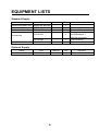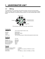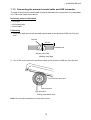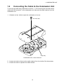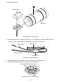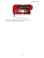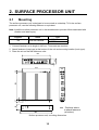
1
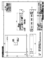
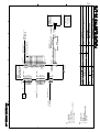
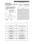
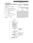
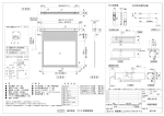
Back
Installation Manual
WIRED TRAWL SONAR
TS-331A
SAFETY INSTRUCTIONS...................................................................................... i
SYSTEM CONFIGURATION................................................................................. ii
EQUIPMENT LISTS ............................................................................................. iii
1. UNDERWATER UNIT ....................................................................................... 1
1.1 Wiring ........................................................................................................................... 1
1.2 Connecting the Cable to the Underwater Unit ............................................................... 7
2. SURFACE PROCESSOR UNIT ..................................................................... 10
2.1 Mounting..................................................................................................................... 10
2.2 Wiring ..........................................................................................................................11
3. CATCH SENSOR (OPTION) .......................................................................... 12
PACKING LISTS ............................................................................................... A-1
OUTLINE DRAWING......................................................................................... D-1
SCHEMATIC DIAGRAM ....................................................................................S-1
SAFETY INSTRUCTIONS
CAUTION
WARNING
ELECTRICAL SHOCK HAZARD
Attach protection earth
securely to the ship's body.
Do not open the equipment.
Only qualified personnel
should work inside the
equipment.
The protection earth is required
for the surface processor unit to
prevent electrical shock.
When using a two prong
outlet, use the adaptor with the
earth wire (pin).
Turn off the power at the switchboard
before beginning the installation.
Fire or electrical shock can result if the
power is left on.
Observe the following compass safe
distances to prevent deviation of a
magnetic compass:
Do not install the surface processor unit
where it may get wet from rain or water
splash.
Surface
processor unit
Water in the equipment can result in fire,
electrical shock or damage to equipment.
Be sure that the power supply is
compatible with the voltage rating of
the equipment.
Connection of an incorrect power supply
can cause fire or damage the equipment.
i
Standard
Steering
0.3 m
0.3 m
SYSTEM CONFIGURATION
PC Monitor
(User supply)
Power
source
110/220 VAC
1f, 50/60Hz
Surface Processor Unit
Mouse
Keyboard
Winch
Cable Block
SHIPBOARD SECTION
UNDERWATER SECTION
Underwater Unit
: Standard supply
: Optional supply
: Local, user supply
Catch Sensor (option)
(4 max.)
ii
EQUIPMENT LISTS
Standard Supply
Name
Surface Processor Unit
Underwater Unit
Installation Materials
Accessories
Spare Parts
Type
MODEL854-000-002
MODEL854-000-360
CP01-01400
Code No.
-
Qty
1
1
1
FP03-01100
-
1
FP01-01200
SP01-01300
-
1
1
Remarks
Power cable
Test cable, mouse
(w/USB adapter +
MS-14S connector)
U/W connector
Fuse
Optional Supply
Name
Catch Sensor
Type
CS-400
Code No.
000-060-120
iii
Qty
1
Remarks
Maximum four available.
This page is intentionally left blank.
1. UNDERWATER UNIT
1.1
Wiring
The underwater unit is connected to the surface processor unit with an armored coaxial
cable (user supply, maximum length: 3000 m). If necessary, a winch (local supply) is placed
between the underwater unit and the surface processor unit. Recommended cable is shown
below.
Outer conductor
Armored wire (inner)
Conductor
Armored wire (outer)
Insulator
Recommended armored coaxial cable, sectional view
Construction
Conductor:
Insulator:
Screen:
Jacket:
Armor wire:
1.9 mm² plain copper strand (1 ea)
Polyethylene
Served plain copper
Polyethylene
Two contrahelical layers of high tensile galvanized steel wires
Mechanical
Diameter:
Weight in air:
Weight in seawater:
Rec. bending radius:
Breaking strength:
Working load:
11.2 mm
452 kg/km
366 kg/km
230 mm
72 kN
18 kN
Electrical
Maximum working voltage:
Conductor resistance:
Impedance:
Attenuation:
1.9 kVDC
9.8 Ω/km for conductor, 6.9Ω/km for screen
40 Ω
10.5 dB/km at 1 MHz, 23.3 dB/km at 5 MHz
1
1. UNDERWATER UNIT
1 .1.1 Tension relief system
The first thing to do is to construct the tension relief system, an example of which is shown
below. The connection of the underwater unit is described in the next section.
Rubber plates
(2 pcs.)
Buoy (Styrofoam)
Twist the cable grip termination
around the wire.
(Recommended cable grip is:
P/N: 2202148, LOT: S1313 PMI
Dia.: 437"-456" LAY LHL
PMI Industries, Inc.)
Wire clamps
Leave slack in cable.
Attach a spring-loaded hook (shackle)
at the fold of the cable grip termination.
Run the bridle through the hook on the shackle.
Bridle
(crowfoot,
steel wire)
Head rope
Underwater unit
Typical tension relief system
2
1. UNDERWATER UNIT
1.1.2 Connecting the armored coaxial cable and U/W connector
The end of the armored coaxial cable should be fabricated for connection to the underwater
unit. Follow the steps shown below.
Necessary parts for fabrication
• Vinyl tape
• Self-binding tape
• Shrink tubes
Fabricating
1. Wrap vinyl tape around the armored coaxial cable at the position of 280 mm from the
end.
Vinyl tape
280 mm
Underwater side
Armored coaxial cable
Winding vinyl tape
2. Cut off the outer armor wire as shown below at the position of 280 mm from the end.
Cut off the outer armor wire.
Outer armor wire
Inner armor wire
Cutting outer armor wire
Note: Do not make scratches on inner armor wires.
3
1. UNDERWATER UNIT
3. Wrap vinyl tape around the wire at the position of 240 mm from the end, and then
untwist inner armors at the position of taping.
4. Cut each wire off.
Cut off inner armor wires.
Outer armor
Vinyl tape
Inner armor
240 mm
40 mm
Trimming inner armors
5. Wind self-binding tape (local supply) around the end of the inner armor, and then slip the
shrink tube (length: approx. 100 mm, type: e.g. TMX 12.7/4.1 manufactured by Novatio,
local supply) onto the cable.
Slip a shrink tube.
Self-binding tape
Self-binding tape and shrink tubing
4
1. UNDERWATER UNIT
6. Shift the shrink tube to the position as below, and heat it.
Note: Heat the shrink tubing from its center to allow air to pass out.
Shrink tube
Heating the shrink tubing
7. Wrap vinyl tape with uniform thickness around the shrink tube.
Inner: Shrink tube
Outer: Vinyl tape
Vinyl tape and shrink tubing
8. Fabricate the end of the cable as below.
mm
20
20 mm
Twist the outer conductor.
20 mm
Fabricating the cable end
5
1. UNDERWATER UNIT
9. Pass the shrink tubing (type: e.g. TMX 12.7/4.1, local supply) through the U/W
connector.
10. Pass the shrink tubing (type: e.g. TMX 4.8/1.5, local supply) into both of the cables of
the U/W connector.
11. Solder cables as shown below.
Soldering
Twisted uctor
d
outer con
Armored coaxial cable
Core
Soldering
White
Shrink tube
U/W connector
Black
Shrink tube
Soldering the armored coaxial cable and underwater unit cable
12. Shift the shrink tube to the position covering the connection position.
13. Heat the shrink tube.
14. Wind self-binding tape around the connection of the armored coaxial cable and U/W
connector, and then wrap vinyl tape with uniform thickness over self-binding tape.
15. Slide the shrink tube onto the connection point.
16. Heat the shrink tube from its center.
Note: Heat the shrink tubing from its center to allow air pass out.
17. Wind vinyl tape around the shrink tube.
18. Finally, wind vinyl tape as below, overlapping by 1/2 the width of the tape.
370 mm
End of shrink tubing (127/41)
U/W connector
Taping
6
1. UNDERWATER UNIT
1.2
Connecting the Cable to the Underwater Unit
To connect the cable assy. fabricated in section “1.1.2 Connecting the armored coaxial
cable and U/W connector” to the underwater unit, dismount the cable retainer from the
underwater unit.
1. Unfasten six hex. bolts to open the underwater unit cover.
Hex. bolt (6 pcs.)
Clamp assy
Underwater unit, cover removed
2. Loosen two bolts to dismount the cable retainer from the inside of the clamp assy.
3. Loosen two bolts to separate the cable retainer.
7
1. UNDERWATER UNIT
Cable retainer
Clamp assy
Cable retainer and clamp assy
4. Bend the cable assy. (connected in section 1.1.2), and fasten it with the cable retainer.
The armor of the coaxial cable should be placed into the narrower groove.
U/W connector
Wider groove
370 mm
Armor coaxial cable
Narrower groove
Cable assy w/cable retainer
5. Reassemble the cable retainer, and then reattach it to the clamp assy.
6. Connect the U/W connector to the top of the vertical sonar.
Connect the U/W connector to here.
Underwater unit, cover removed
8
1. UNDERWATER UNIT
Notch
Underwater unit, cover removed
7. Run the armored coaxial cable through the notch on the housing.
8. Reattach the underwater unit cover with six bolts.
9
2. SURFACE PROCESSOR UNIT
2.1
Mounting
The surface processor unit is designed to be mounted on a desktop. To fix the surface
processor unit, use the following fastener or equivalent.
Note: Install the surface processor unit in the wheelhouse to prevent effects associated with
vibration and water spray.
Supplier
3M
Name
Dual lock fastener
Type
SJ-3551J
SJ-3552J
1. Cut each fastener so its length is 440 mm. Three sets are required.
2. Attach fasteners (loop-type) at the bottom of the unit and mounting location (hook type).
3. Place the unit so that the fasteners unite.
2
86
433
433
88
27
9
454
20
86
: Positions where
to attach fasteners.
(at bottom)
483
Surface processor unit, mounting dimensions
10
2. SURFACE PROCESSOR UNIT
2.2
Wiring
To underwater unit
(via MS-14S connector)
To Mouse
(via USB-P/S2 converter)
(Supplied)
Power cord
54-080100
(Supplied)
Power supply*
To Monitor, D-sub 15P
(User supply)
To Keyboard
(Local supply)
Ground cable
IV-2.0SQ
(Local supply)
*: Separate the power cable at least 300 mm
from high tension cables.
To ship's ground
Surface processor unit, rear view
Fabricating the MS-14S connector
Use cable DPYCY-1.5 (Japan industrial standard cable) or equivalent between the MS-14S
connector and armored coaxial cable. The length is determined according to the distance
between the bridge and winch.
Connect the DPYCY-1.5 and
armored coaxial cable as below.
After connection, wrap the cable
with vinyl tape.
Solder lead wire to armor and connect
the twisted armor to A pin of connector.
B
+ (from B)
C
A
- (from C)
Armor
DPYCY-1.5 cable
MS-14S connector
Soldering
Taping
DPYCY-1.5, sectional view
Armor
Conductor
2
S = 1.5 mm
φ = 1.56 mm
Core
Sheath
φ = 11 mm
11
Armored coaxial cable
3. CATCH SENSOR (OPTION)
Max. four optional catch sensors can be mounted depending on the trawl.
1. Fasten the four ropes (local supply) to fix the catch sensor to the trawl.
2. Use rubber ropes and shackles (local supply) to attach the sensor wire to the trawl.
3. Use rubber rope, a shackle and ropes (local supply) to fix the catch sensor on the
opposite side of the sensor wire.
Sensor wire
(Step 2)
Catch sensor
Shackle
(Step 2)
Rubber rope
(Step 3)
Shackle
(Step 3)
Rubber rope
(Step 2)
Rope
(Step 1)
12
Ropes
(Step 3)
NAME
ACCESSORIES
38-076
WINDOWS XP CD-ROM
INSTALLATION MATERIALS
999-999-083
54-080100*
999-999-075
(略図の寸法は、参考値です。 DIMENSIONS IN DRAWING FOR REFERENCE ONLY.)
(*1)は、ダミーコードに付き、注文できません。
(*1)THIS CODE CANNOT BE ORDERED.
POWER CORD
電源コード
工事材料
MOUSE
マウス(USBアダプター付き)
999-999-037
999-999-077
CD-ROM(FOR COMMUNICATION
BOARD)
WINDOWS XP SOFT PACK CD-ROM
PCI16C550
999-999-078
TS-331A_EXE
999-999-079
D845GLVA
999-999-080
1A 250V
999-999-081
2A 250V
000-060-122
MODEL854-000-002
(*1)
1
(*1)
1
(*1)
1
(*1)
1
(*1)
1
(*1)
1
(*1)
2
(*1)
2
1
Q'TY
NAME
OPERATOR'S MANUAL
取扱説明書
INSTALLATION MANUAL
装備要領書
図書
U/W CONNECTOR
U/Wコネクター
MS CONNECTOR
MSコネクター
BOLT SET
ボルトセット
TS-331A SARFACE PROCESSOR UNIT
DESCRIPTION/CODE №
通信ボード用ドライバーCD-ROM
FD(TS-331A APPLECATION)
TS-331AアプリケーションFD
CD-ROM(FOR MOTHER BOARD)
OUTLINE
SPARE PARTS
UNIT
マザーボード用ドライバーCD-ROM
付属品
FESE
管入りヒューズ
FESE
管入りヒューズ
予備品
SURFACE PROCESSOR UNIT
操作部
ユニット
PACKING LIST
DOCUMENT
OUTLINE
1/1
01AO-X-9852
000-151-384
OME-13210-*
000-151-385
IME-13210-*
999-999-073
854-460-304
999-999-074
854-460-335
999-999-076
W3/8X40
DESCRIPTION/CODE №
01AO-X-9852 -0
1
1
(*1)
1
(*1)
1
(*1)
1
Q'TY
A-1
A-2
PACKING LIST
01AO-X-9851 -0
1/1
TS-331A UNDERWATER UNIT
N A M E
ユニット
O U T L I N E
DESCRIPTION/CODE №
Q'TY
UNIT
MODEL854-000-360
発信器
1
UNDERWATER UNIT
000-060-118
(略図の寸法は、参考値です。
DIMENSIONS IN DRAWING FOR REFERENCE ONLY.)
01AO-X-9851
Y. Hatai
署名は検
証されて
いません
。
電子署名者 : Yoshitoshi Hatai
DN: cn=Yoshitoshi Hatai,
o=Furuno, c=JP
日付 : 2004.10.13 16:56:52 +
09'00'
Yoshitoshi
Hatai
D-1
C
B
A
110/220VAC
1φ,50/60Hz
NOTE
*1.
*2.
*3.
*4.
*5.
SHIPYARD SUPPLY.
OPTION.
FACTORY FITTED.
GROUND THRU CONNECTOR CLAMP.
USER SUPPLY.
注記
*1)造船所手配。
*2)オプション。
*3)工場にて取付済み。
*4)コネクタクランプでアースに落とす。
*5)ユーザー手配。
1
H. MAKI
kg
C1321-C01- A
NAME
名称
TITLE
半田付
SOLDERED
CS-400(MAX.4)
CATCH SENSOR
キャッチセンサー
1
2
TS-331A
ワイアードトロールソナー
クロ BLK
シロ WHT
U/W CONNECTOR
発信器
UNDERWATER UNIT
Model854-000-360
INTERCONNECTION DIAGRAM
WIRED TRAWL SONAR
DWG No.
MASS
DPYCY-1.5 *1
VGAモニター *5
VGA MONITOR
鎧装同軸ケーブル
*5
ARMORED COAXIAL CABLE
(MAX.3000m)
Sync:H31.5kHz,V60Hz,TTL
RGB:Analog 0.7Vpp(75Ω)
*5
MONITOR CABLE
SCALE
*5
4
相互結線図
MS-14S
*4
D-sub15P
3
APPROVED
B
C
A
1
2
3
4
5
6
7
8
9
10
11
12
13
14
15
GND
*1
IV-2.0SQ
+
GND
SONAR HEAD
SIG-R
SIG-G
SIG-B
NC
NC
GND
GND
GND
NC
GND
GND
NC
H_SYNC
V_SINC
NC
TAKAHASHI.T
DRAWN
Feb. 7, '05
CHECKED
110/220VAC
L AC
N AC
G GND
DATA IN/OUT
NC
GND
+5V
KCLK
NC
DATA IN/OUT
NC
GND
+5V
KCLK
NC
P/N54-080100,1.2m
DIN6
1
2
3
4
5
6
Model854-000-002
1
2
3
4
5
6
*5
1.5m
USB-P/S2
SURFACE PROCESSOR UNIT
操作部
KEYBOARD
マウス
MOUSE
2
S-1
The paper used in this manual
is elemental chlorine free.
FURUNO Authorized Distributor/Dealer
9-52 Ashihara-cho,
Nishinomiya 662-8580, JAPAN
Telephone :
0798-65-2111
Fax
0798-65-4200
:
All rights reserved.
Printed in Japan
Pub. No. IME-13210-A
( HIMA ) TS-331A
FIRST EDITION : FEB. 2005
*00015138510*
*00015138510*
*00015138510*
*IME13210A00*
*IME13210A00*
*IME13210A00*