1
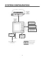
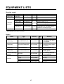
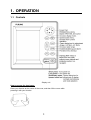
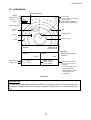
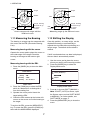
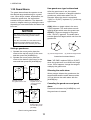
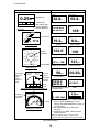
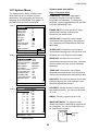
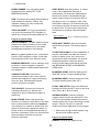
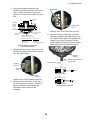
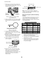
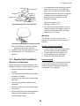
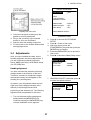
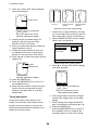
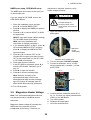
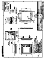
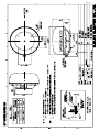
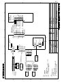
Back
MARINE RADAR
MODEL 1623
TABLE OF CONTENTS
SAFETY INSTRUCTIONS......................... ii
1.24 Outputting Target Position to a
Plotter .............................................. 13
1.25 Turning Navigation Data On/Off ........ 14
1.26 Setting up Nav Data Displays ........... 14
1.27 System Menu ................................... 16
FOREWORD............................................ iv
SYSTEM CONFIGURATION..................... v
EQUIPMENT LISTS................................. vi
2. MAINTENANCE, TROUBLESHOOTING
.........................................................18
1. OPERATION........................................ 1
2.1
2.2
2.3
2.4
2.5
2.6
2.7
2.8
1.1
1.2
1.3
1.4
1.5
1.6
1.7
1.8
1.9
1.10
1.11
1.12
1.13
1.14
1.15
1.16
1.17
1.18
1.19
1.20
1.21
1.22
Controls ............................................. 1
Indications.......................................... 2
Turning Power On/Off......................... 3
Transmitting, Standby......................... 3
Adjusting Display Contrast, Brilliance . 4
Choosing the Range........................... 4
Receiver Sensitivity............................ 4
Suppressing Sea Clutter..................... 5
Suppressing Rain Clutter.................... 6
Measuring the Range ......................... 6
Measuring the Bearing ....................... 7
Shifting the Display............................. 7
Zoom ................................................. 8
User Menu Overview.......................... 8
Heading Line...................................... 9
Interference Rejector.......................... 9
Noise Rejector ................................. 10
Echo Trail, Trail Brilliance ................. 10
Echo Stretch..................................... 10
Guard Alarm..................................... 11
Watchman........................................ 12
Suppressing Long-range Rain
Clutter.............................................. 12
1.23 PROG Key ....................................... 13
Maintenance .................................... 18
Replacing the Fuse .......................... 19
Troubleshooting................................ 19
Diagnostics ...................................... 20
Test Pattern...................................... 21
Clearing the Memory ........................ 21
Replacing the Magnetron.................. 21
Replacing the Synchro Belt ............... 21
3. INSTALLATION..................................22
3.1
3.2
3.3
3.4
3.5
Antenna Unit Installation................... 22
Display Unit Installation .................... 25
Wiring .............................................. 26
Adjustments ..................................... 27
Magnetron Heater Voltage................ 29
MENU TREE....................................... MN-1
SPECIFICATIONS ...............................SP-1
PACKING LIST ...................................... A-1
OUTLINE DRAWINGS........................... D-1
INTERCONNECTON DIAGRAM ........... S-1
Declaration of Conformity
i
SAFETY INSTRUCTIONS
Safety Instructions for the Operator
Safety Instructions for the Installer
WARNING
WARNING
Do not open the equipment
unless totally familiar with
electrical circuits and
service manual.
ELECTRICAL SHOCK HAZARD
Do not open the equipment.
Only qualified personnel
should work inside the
equipment.
Only qualified personnel
should work inside the
equipment.
Wear a safety belt and hard
hat when working on the
antenna unit.
Wear a safety belt and hard
hat when working on the
antenna unit.
Serious injury or death can
result if someone falls from
the radar antenna mast.
Serious injury or death can
result if someone falls from
the radar antenna mast.
Do not disassemble or modify the
equipment.
Construct a suitable service platform
from which to install the antenna unit.
Fire, electrical shock or serious injury can
result.
Serious injury or death can result if someone falls from the radar antenna mast.
Turn off the power immediately if water
leaks into the equipment or the equipment is emitting smoke or fire.
Be sure that the power supply is
compatible with the voltage rating of
the equipment.
Continued use of the equipment can cause
fire or electrical shock.
Connection of an incorrect power supply
can cause fire or damage the equipment.
CAUTION
Use only the specified power cable.
Fire or damage to the equipment can result
if a different cable is used.
Use the proper fuse.
Use of a wrong fuse can damage the
equipment and void the warranty.
CAUTION
WARNING LABEL
A warning label is attached to the
equipment. Do not remove the label.
If the label is missing or damaged,
contact a FURUNO agent or dealer
about replacement.
WARNING
To avoid electrical shock, do not
remove cover. No user-serviceable
parts inside.
Observe the following compass safe
distances to prevent interference to a
magnetic compass:
Name: Warning Label (1)
Type: 86-003-1011-1
Code No.: 100-236-230
ii
Standard
compass
Steering
compass
Display
unit
0.50 m
0.30 m
Antenna
unit
1.25 m
0.95 m
COMPLIANCE WITH R&TTE DIRECTIVE 1999/5/EC
This radar complies with the R&TTE Directive 1999/5/EC. In accordance with Article 6-3 of this
directive, FURUNO intends to put this radar on the market of the following countries in EU as
well other markets.
Austria, Belgium, Cyprus, Denmark, Estonia, Finland, France, Germany, Greece, Hungary,
Ireland, Italy, Latvia, Lithuania, Malta, Poland, Portugal, Slovenia, Spain, Sweden, The
Netherlands, United Kingdom, Iceland, Norway
iii
FOREWORD
A Word to the Owner of the
MODEL 1623
Features
Your radar has a large variety of functions, all
contained in a rugged plastic case. All
controls respond immediately to the
operator’s command and each time a key is
pressed the corresponding change can be
seen on the screen.
Congratulations on your choice of the
FURUNO MODEL 1623 Marine Radar.
For over 50 years FURUNO Electric
Company has enjoyed an enviable reputation
for innovative and dependable marine
electronics equipment. This dedication to
excellence is furthered by our extensive
global network of agents and dealers.
The main features of the MODEL 1623 are
Your radar is designed and constructed to
meet the rigorous demands of the marine
environment. However, no machine can
perform its intended function unless installed,
operated and maintained properly. Please
carefully read and follow the recommended
procedures for installation, operation, and
maintenance.
We would appreciate hearing from you, the
end-user, about whether we are achieving our
purposes.
Thank you for considering and purchasing
FURUNO equipment.
iv
•
Daylight viewing radar specially designed
for small craft and sailing yachts.
•
Traditional FURUNO reliability and quality
in a compact, light-weight and low-cost
radar.
•
Compact and light-weight radome
antenna with precision 38 cm center-fed
radiator.
•
High definition 6-inch monochrome LCD
display.
•
Automatic control of sensitivity (gain),
tuning and A/C SEA for simplified
operation.
•
Targets can be displayed in grey tones on
a white background or vice versa, for
optimal viewing under any lighting
conditions.
•
On-screen alphanumeric readout of all
operational information.
•
User programmable nav data displays.
•
[PROG] key provides menu shortcut.
•
Standard features include Display Shift,
EBL, Echo Stretch, Echo Trail, Guard
Alarm, Interference Rejector, VRM, Zoom.
•
Guard zone watches for targets entering
(or exiting) a guard zone.
•
Operates on 12 or 24 V DC power.
SYSTEM CONFIGURATION
ANTENNA
UNIT
RSB-0093
DISPLAY
UNIT
RDP-141
GPS RECEIVER
GP-310B/320B
WIND INDICATOR,
SPEED INDICATOR
NAVIGATOR
or ECHO SOUNDER
(NMEA 0183)
RECTIFIER
PR-62
EXTERNAL
BUZZER
XH3-BZ-L970
12-24 VDC
: Standard supply
100/110/220/230 VAC,
1φ, 50/60 Hz
: Optional supply
: Local supply
v
EQUIPMENT LISTS
Standard supply
Name
Type
Code No.
Qty
Antenna Unit
RSB-0093
—
1
Display Unit
RDP-141
—
1
Installation
Materials*
Spare Parts*
1 set
Remarks
CP03-25301
008-442-280
For antenna unit, including EMI core
CP03-24910
000-080-231
CP03-24920
000-080-232
CP03-24930
000-080-233
CP03-25101
008-441-250
1 set
For display unit, including tapping
screws for mounting hanger
SP03-14301
008-442-270
1 set
Fuse
Antenna cable (10 m)
1 set
Antenna cable (15 m)
Antenna cable (20 m)
*: See packing list at end of manual.
Option
Name
Type
Code No.
Qty
Buzzer Assy.
XH3-BZ-L970
000-146-422
1
With connector, 0.9 m
Cable Assy.
MJ-A7SPF0007-050
000-144-418
1
Connector at one end, 5
m, for NMEA
Cable Assy.
MJ-A15A7F0004-005
000-145-690
1
For NMEA, 0.5 m,
connector at both ends,
(7P-7P/6P)
Cable Assy.
A15A7F0005-020
000-145-691
1
7P-7P, for NMEA, 2 m
Cable Assy.
MJ-A10SPF0003-300
000-130-034
1
Antenna cable, 30 m, for
24 VDC power
Radome Mounting
Bracket
OP03-93
008-445-080
1
For mounting antenna
unit on sailboats
PR-62
000-013-484
PR-62
000-013-485
PR-62
000-013-486
PR-62
000-013-487
Rectifier
vi
Remarks
100 VAC
1
115 VAC
220 VAC
230 VAC
1. OPERATION
1.1 Controls
Display unit
How to remove the hard cover
Place your thumbs at the center of the cover, and then lift the cover while
pressing it with your thumbs.
1
1. OPERATION
1.2 Indications
Simulation mode
Range
Range ring
interval
Zoom
1.5nm
TRAIL
G(IN)
ES H
IR H
FTC
0.5
ZOOM
WATCH
SIM
Echo trails
Guard alarm (IN or OUT)
Echo stretch
Interference rejector
Rain clutter suppressor
Watchman
Guard
zone
EBL
Cursor
Heading line
Range rings
VRM
34°44.135 N
135°44.135 E
Position
Speed
5.0 kt
EBL bearing
VRM range
EBL
VRM
45.0°
1.25 nm
Nav data
(Requires appropriate
sensors.)
Course
135°
RNG 0.62nm
BRG 283.2°
TTG 0H7M
Range, bearing and
time-to-go to cursor
location
(Cursor latitude and
longitude position
also available if radar
is interfaced with
a navigator.)
Indications
About the LCD
This high quality LCD displays better than 99.9% of its picture elements. The remaining 0.01%
may drop out or light, however this is not an indication of malfunction; it is characteristic of the
LCD.
2
1. OPERATION
1.3 Turning Power On/Off
1.4 Transmitting, Standby
Press the [POWER/BRILL] key to turn on the
power. The unit beeps, the startup screen
appears, and then the equipment checks the
ROM and RAM for proper operation and
displays program number. The ROM and
RAM check shows OK or NG (No Good). If
NG appears, try to press any key except the
[POWER/BRILL] key to start operation.
However, the equipment may not work
properly. Contact your dealer for advice.
After the power is turned on and the
magnetron has warmed up, “ST-BY”
(Standby) appears, indicating the radar is
ready to transmit radar pulses.
To toggle between transmit and standby, do
the following:
1. Press the [POWER/BRILL] key
momentarily to show the
brilliance/contrast adjustment window.
BRILL/CONTRAST
TX/STBY - PRESS [MODE]
LOW
CONT:
6" LCD MARINE RADAR
MODEL 1623
HIGH
4
LOW
BRILL:
FURUNO ELECTRIC CO., LTD.
ROM : OK RAM : OK
Program No: 0359183-XX.XX
HIGH
9
[MENU/ESC] : Exit.
XX.XX = Program version no.
Startup screen
After the completion of the startup test, a
timer displays the time remaining for warm up
of the magnetron (the device which transmits
radar pulses), counting down from 1:00 to
0:00.
To turn off the power, press and hold down
the [POWER/BRILL] key until the screen
goes blank. The time remaining until power is
turned off is counted down on the screen.
Note 1: In a cold environment the screen
appears “foggy” when the power is turned on
but is soon restored to normal condition.
Note 2: The example screens shown in this
manual may not match the screens you see
on your display. The screen you see depends
on your system configuration and equipment
settings.
3
Brilliance/contrast adjustment window
2. Press the [MODE] key to go to standby
and transmit alternately.
Note: If you attempt to transmit before
“ST-BY” appears, the buzzer sounds and
the radar does not transmit pulses. Wait
until “ST-BY” appears.
3. Press the [MENU/ESC] key to close the
window.
When radar pulses are transmitted the radar
receive is automatically tuned. Echoes
appear in four levels of digitized video
according to echo strength. When a target is
beneath a marker (VRM, EBL, heading line,
range ring) the part of the marker where the
target lies is displayed in reverse video.
Note: This can be done with the
above-mentioned procedure or the PROG
key if it is so programmed. For detail, see
1.26 “PROG Key”.
1. OPERATION
1.5
Adjusting Display
Contrast, Brilliance
Range
Range ring
interval
6.0 nm
2.0
1. Press the [POWER/BRILL] key
momentarily to show the
brilliance/contrast adjustment window.
BRILL/CONTRAST
TX/STBY - PRESS [MODE]
LOW
CONT:
HIGH
EBL - - - .-°
VRM - - - -nm
4
LOW
BRILL:
HIGH
RNG 03.2nm
BRG 60.2°
TTG 02H21M
Location of range and range ring
interval indications
9
[MENU/ESC] : Exit.
Brilliance/contrast adjustment window
2. Press ◄ or ► to adjust contrast.
3. Press ▲ or ▼ to adjust brilliance.
4. Press the [MENU/ESC] key to escape.
Note 1: Windows other than menu windows
are erased when there is no operation within
about 10 seconds.
Note 2: When the power is reapplied after
turning off the equipment with minimum
brilliance, the radar starts up with minimum
brilliance, after the startup screen appears.
Adjust the brilliance as necessary.
1.6 Choosing the Range
The range selected automatically determines
the range ring interval, the number of range
rings and pulse repetition rate.
Press the [RANGE+] or [RANGE-] key to
select a range. The range and range ring
interval appear at the top left corner on the
screen.
1.7 Receiver Sensitivity
The [GAIN] key adjusts the sensitivity (gain)
of the receiver. It works in precisely the same
manner as the volume control of a broadcast
receiver, amplifying the signals received.
The sensitivity is adjusted automatically
according to sea conditions, and you may
also further adjust it manually to fine tune.
The proper setting is such that the
background noise is just visible on the
screen.
If you set up for too little sensitivity, weak
echoes may be missed. On the other hand
excessive sensitivity yields too much
background noise; weak targets may be
missed because of the poor contrast between
desired echoes and the background noise on
the display.
1. Press the [GAIN] key consecutively until
the display shown below appears.
GAIN
AUTO
: MODERATE
MANU
20
[GAIN] : A/C SEA MENU
[MENU/ESC] : Exit.
Gain adjustment window
4
1. OPERATION
2. Press ▲ or ▼ to choose AUTO or MANU
as appropriate.
Automatic gain adjustment
a) Press ► to open the automatic gain
options window.
Always leave a little sea clutter visible on the
Screen, first adjusting automatically and then
fine tuning with the manual control as
necessary.
ROUGH
MODERATE
CALM
Automatic gain options
b) Press ▲ or ▼ to choose ROUGH,
MODERATE or CALM depending on
sea conditions.
c) Press ◄ to close the window.
Sea clutter at screen center
Manual gain adjustment
1. Press the [GAIN] key consecutively until
the display shown below appears.
While observing the screen and the gain
tuning bar, press ◄ or ► to set the gain.
The setting range is 0-100.
A/C SEA
3. Press the [MENU/ESC] key to finish.
AUTO
MANU
1.8 Suppressing Sea Clutter
In rough weather, returns from the sea
surface, called sea clutter, are received over
several miles around own ship and mask
nearby targets. This situation can be
improved by properly suppressing the sea
clutter with the A/C SEA control.
In most cases suppress the clutter until it has
disappeared to leeward, but a little is still
visible windward. If the setting is too low,
targets will be hidden in the clutter, while if it
is set too high, both sea clutter and targets
will disappear from the display.
A common mistake is too over-suppress sea
clutter so that it is completely removed. You
can see how dangerous this can be by setting
up for maximum A/C SEA: A dark zone will
be created near the center of the screen,
causing a loss of close-in targets. This dark
zone is even more dangerous if the sensitivity
has not been properly adjusted.
5
: MODERATE
20
[GAIN] : A/C RAIN MENU
[MENU/ESC] : Exit.
A/C SEA adjustment window
2. Press ▲ or ▼ to choose AUTO or MANU
as appropriate.
Automatic A/C SEA adjustment
a) Press ► to open the automatic A/C
SEA options window.
ROUGH
MODERATE
CALM
A/C SEA options
b) Press ▲ or ▼ to choose ROUGH,
MODERATE or CALM depending on
sea conditions.
c) Press ◄ to close the window.
1. OPERATION
Manual A/C SEA adjustment
1.10 Measuring the Range
While observing the screen and the A/C
SEA tuning bar, press ◄ or ► to set the
A/C SEA. The setting range is 0-100.
The bearing to a target can be measured by
the range rings, by the cursor and by the
VRM (Variable Range Marker).
4. Press the [MENU/ESC] key to finish.
1.9 Suppressing Rain Clutter
The vertical beamwidth of the antenna is
designed to see surface targets even when
the ship is rolling. However, by this design the
antenna will also pick up rain clutter (rain,
snow, or hail) in the same manner as normal
targets. The illustration below shows the
appearance of rain clutter on the display.
The A/C RAIN control adjusts the receiver
sensitivity as the A/C SEA control does but
rather in a longer time period (longer range).
The higher the setting the greater the
anti-clutter effect.
Measuring range by the cursor
Operate the cursor pad to place the cursor on
the inside edge of the target. Read the range
to the cursor at the bottom right corner of the
display.
Measuring range by the range rings
Count the number of rings between the
center of the display and the target. Check
the range ring interval and judge the distance
of the echo from the inner edge of the nearest
ring.
Note: The range rings can be turned on or off
with RINGS on page 1 of the System menu.
Measuring range by the VRM
1. Press the [MARK] key to show the Mark
menu.
MARK MENU
[GAIN] : EBL
[ALARM] : VRM
[MARK] : TLL OUTPUT
Rain clutter at screen center
1. Press the [GAIN] key consecutively until
the display shown below appears.
A/C RAIN
65
[GAIN] : GAIN MENU
[MENU/ESC] : Exit.
A/C RAIN adjustment window
2. While observing the screen and the A/C
RAIN tuning bar, press ◄ or ► to adjust
the A/C RAIN. The setting range is 0-100.
3. Press the [MENU/ESC] key to finish.
Mark menu
2. Press the [ALARM] key to display the
VRM, which is a dashed ring to
distinguish it from the range rings.
3. Operate the cursor pad to place the VRM
on the inside edge of the target.
4. Check the VRM readout at the bottom left
corner on the screen to find the range to
the target.
To anchor the VRM on the screen, press the
[MENU/ESC] key. To erase the VRM, press
the [ALARM] key twice with the MARK MENU
displayed.
6
1. OPERATION
6.0 nm
6.0 nm
2.0
2.0
Target
Cursor
EBL - - - .-°
VRM 2.91nm
RNG 2.22nm
BRG 45.62°
TTG 02H21M
Cursor
EBL
VRM
VRM
range
Target
Range, bearing
and time-to-go
to cursor
location
How to measure the range with the
VRM and cursor
EBL
bearing
Range, bearing
and time-to-go
to cursor
location
RNG 2.22nm
BRG 45.62°
TTG 02H21M
EBL 45.62°
VRM - - - -nm
Measuring range by the EBL and cursor
1.11 Measuring the Bearing
1.12 Shifting the Display
The bearing to a target can be measured with
the cursor and the EBL (Electronic Bearing
Line).
Own ship position, or sweep origin, can be
displaced manually or automatically to
expand the view field without switching to a
longer range. The default shift method is
manual.
Measuring bearing with the cursor
Operate the cursor pad to place the cursor on
the inside edge of the target. Read the
bearing to the target at the bottom right
corner.
Measuring bearing with the EBL
1. Press the [MARK] key to show the Mark
menu.
If shift is activated when nav data is displayed,
the nav data is automatically erased.
1. Use the cursor pad to place the cursor
where you want to shift own ship position.
2. Press the [MODE] key to show the
Display Mode menu.
DISPLAY MODE
MARK MENU
SHIFT (MANUAL)*
NORMAL
[GAIN] : EBL
[ALARM] : VRM
[MARK] : TLL OUTPUT
ZOOM
NAV DISP
OFF
ON
[MENU/ESC] : Exit
Mark menu
2. Press the [GAIN] key to show the EBL,
which is a dashed line to distinguish it
from the heading line.
3. Operate the cursor pad to bisect the
target with the EBL.
4. Check the EBL readout at the bottom left
corner on the screen to find the bearing to
the target.
To anchor the EBL, press the [MENU/ESC]
key. To erase the EBL, press the [GAIN] key
twice with the MARK MENU displayed.
7
Display mode menu
3. Press ▲ to choose SHIFT (MANUAL).
Note: If SHIFT (AUTO) is shown, open
the System menu and set SHIFT MODE
to MANUAL. For further details, see
SHIFT MODE on page 17.
4. Press the [MENU/ESC] key to close the
menu.
1. OPERATION
6.0 nm
2.0
Choose
manual
SHIFT
mode.
Select where to shift
with the cursor.
Cursor
+
Zoom
Window
Shifted display
EBL - - - .-°
VRM - - - -nm
Zoom display
How the manual shift works
To cancel the shifted display, open the
Display Mode menu, choose NORMAL and
then press the [MENU/ESC] key.
RNG 4.43nm
BRG 231.3°
TTG: 02H21M
To cancel the zoom display, open the Display
Mode menu, choose NORMAL and then
press the [MENU/ESC] key. To choose new
zoom location, return to the NORMAL mode
and then repeat the zoom procedure.
1.13 Zoom
The zoom feature allows you to double the
size of a selected area.
If zoom is activated when nav data is
displayed, the nav data is automatically
erased.
1. Use the cursor pad to place the cursor
where you want to zoom.
2. Press the [MODE] key to show the display
mode menu.
1.14 User Menu Overview
The User menu, consisting of three pages of
menus, contains 10 items which the user may
set according to conditions.
1. Press the [MENU] key to open the User
menu.
*
TX/ST-BY
ST-BY
INT REJECTION
: LOW
ECHO STRETCH : LOW
FTC
: OFF
NOISE REJECTION: LOW
(1/2)
[MENU/ESC] : Exit.
SELECT DISPLAY MODE
* = "P" shows current function of PROG key
SHIFT (MANUAL)*
User menu, page 1
NORMAL
2. Use ▲ or ▼ to scroll the menu to display
desired item in reverse video.
ZOOM
NAV DISP
P
OFF
ON
Page 2
WATCHMAN TIME OFF
HDG LINE OFF
ECHO TRAIL
: OFF
TRAIL BRILLIANCE : LOW
SYSTEM MENU ...
[MENU/ESC] : Exit
* AUTO may appear instead of MANUAL
depending on shift method selected.
(2/2)
[MENU/ESC] : Exit.
Display mode menu
User menu, pages 2
3. Press ▼ to choose ZOOM.
4. Press the [MENU/ESC] key to close the
menu. “ZOOM” appears at the top left
corner when the zoom feature is turned
on.
8
1. OPERATION
3. Press ► to show the options window for
the item selected. For example, the
illustration below shows the interference
rejector options window.
1.15 Heading Line
The heading line indicates the ship’s heading
and it is the solid line which appears at zero
degrees on the bearing scale.
OFF
LOW
MEDIUM
HIGH
To temporarily erase the heading line to look
at targets existing dead ahead of own ship,
do the following:
Interference rejector options
4. Press ▲ or ▼ to choose option desired.
5. Press ◄ to continue menu operation, or
press the [MENU/ESC] key to register
your selection and close the User menu.
User menu description
Item
TX/ST-BY
INT
REJECTION
ECHO
STRETCH
FTC
NOISE
REJECTION
WATCHMAN
TIME
HDG LINE
OFF
ECHO TRAIL
TRAIL
BRILLIANCE
SYSTEM
MENU
1. Press the [MENU/ESC] key to open the
User menu.
2. Press ▲ or ▼ to choose HDG LINE OFF
from page 2.
3. Press ► to turn the heading line off. The
line stays off while ► is pressed.
4. Press the [MENU/ESC] key to close the
menu.
Description
Sets radar in transmit or
stand-by status.
Rejects radar interference.
Stretches echoes in range
direction or range and bearing
direction.
Reduces rain clutter.
Rejects noise.
Periodically checks for targets
in guard zone.
Temporarily turns the heading
line off.
Shows echo movement in
afterglow.
Adjusts echo trail brilliance.
1.16 Interference Rejector
Mutual radar interference may occur in the
vicinity of another shipborne radar operating
in the same frequency band (9 GHz). It is
seen on the screen as a number of bright
spikes either in irregular patterns or in the
form of usually curved spoke-like dotted lines
extending from the center to the edge of the
picture. This type of interference can be
reduced by activating the interference rejector
circuit. “IR” and the rejection level indicator
“L,” “M” or “H” appear at the top right corner
when the interference rejector circuit is on.
Opens the system menu. For
description see paragraph
1.30.
Appearance of interference
Turn off the interference rejector when no
interference exists, to avoid missing small
targets.
1. Press the [MENU/ESC] key to open the
User menu.
9
1. OPERATION
2. Press ▲ or ▼ to choose INT REJECTION
from page 1.
3. Press ► to open the options window.
4. Press ▲ or ▼ to choose OFF, LOW,
MEDIUM or HIGH as appropriate.
5. Press the [MENU/ESC] key to finish.
1.17 Noise Rejector
The noise rejector suppresses white noise,
which appears on the screen as many dots
scattered randomly over the display.
1. Press the [MENU/ESC] key to open the
User menu.
2. Press ▲ or ▼ to choose NOISE
REJECTION from page 1.
3. Press ► to open the options window.
4. Press ▲ or ▼ to choose OFF, LOW or
HIGH as appropriate.
5. Press the [MENU/ESC] key to close the
menu.
1.18 Echo Trail, Trail Brilliance
Echo trails are the afterglow of target echoes
that represent their movements relative to
own ship. They are useful for monitoring
target movement.
TRAIL
Trail time
Echo trail
3. Press ► to open the options window.
OFF
30sec
1min
3min
6min
CONTIN.
4.
5.
6.
7.
8.
9.
Echo trail options
Press ▲ or ▼ to choose appropriate time.
Press ◄ to close the options window.
Press ▼ to choose TRAIL BRILLIANCE.
Press ► to open the options window.
Press ▲ or ▼ to choose LOW or HIGH
as appropriate.
Press the [MENU/ESC] key to close the
menu.
1.19 Echo Stretch
On long ranges target echoes tend to shrink,
making them difficult to see. To enhance
target video on long ranges, use the echo
stretch feature.
1. Press the [MENU/ESC] key to open the
User menu.
2. Press ▲ or ▼ to choose ECHO
STRETCH from page 1.
3. Press ► to open the options window.
4. Press ▲ or ▼ to choose OFF, LOW or
HIGH as appropriate. LOW stretches
echoes in the bearing direction; HIGH
stretches echoes in the range and bearing
directions. The display shows “ES L” or
“ES H” at the top right corner depending
on your selection.
5. Press the [MENU/ESC] key to close the
menu.
ES L
Echo trails
1. Press the [MENU/ESC] key to open the
User menu.
2. Press ▲ or ▼ to choose ECHO TRAIL
from page 2.
Echo
Echo Stretch
OFF
ES H
Brg dir.
Brg dir.
Echo Stretch
LOW
Echo Stretch
HIGH
Rng
dir.
How echo stretch works
10
1. OPERATION
1.20 Guard Alarm
How guard zone type is determined
The guard alarm allows the operator to set
the desired range and bearing for a guard
zone. When ships, islands, landmasses, etc.
violate the guard zone, the audio alarm
sounds to call your attention. The alarm will
sound on targets entering or exiting the zone
depending on zone status after the alarm has
been set.
After the guard zone is set, the system
checks for the existence of targets inside the
guard zone, which takes about 8 to 12
seconds. When the check is completed,
“G(IN)” or “G(OUT)” replaces G(---) at the top
right corner.
NOTICE
* The alarm should not be relied upon as the
sole means for detecting possible collision
situations.
G(IN): When no target exists in the zone,
"G(IN)" appears. The audio alarm sounds
against targets which enter the guard zone.
G(OUT): If there are targets in the guard
zone, "G(OUT)" appears. The audio alarm
sounds against all targets which exit from the
guard zone.
* A/C SEA, A/C RAIN, FTC and GAIN controls
should be properly adjusted to be sure the
weak echoes will not be missed by the alarm.
Setting a guard zone
1. Operate the cursor pad to place the
cursor at the top left corner for the zone
and then press the [ALARM] key.
2. Operate the cursor pad to place the
cursor at the bottom right corner for the
zone and then press the [ALARM] key.
Guard
zone
to set
(a) Inward target alarm
(b) Outward target alarm
Inward and outward alarms
Note: "UP RNG" replaces G(IN) or G(OUT)
when the guard zone is not within the range
in use. If this happens, change the range to
redisplay the guard zone.
G(---)
Silencing the audio alarm
Drag cursor
here.
Mentally create
the guard zone to set.
When a target violates the guard zone, the
target flashes and the audio alarm sounds.
You can silence the audio alarm with the
[ALARM] key.
1) Drag cursor to
top left corner for
zone and press
[ALARM].
G(---)
Canceling the guard zone and guard
alarm
Press and hold down the [ALARM] key until
the guard zone is erased.
G(---)
Guard
zone
Drag cursor
here.
Guard zone completed. 2) Drag cursor to
bottom right corner
for zone and press
[ALARM].
How to set a guard zone
11
1. OPERATION
1.21 Watchman
Watchman transmits the radar for one minute
to check if a target has entered or exited the
guard zone from the previous transmission. If
no change is found, the radar goes into
standby for the number of minutes set for the
watchman feature. If change is found, the
audio alarm sounds, watchman is canceled
and the radar transmits. This feature is useful
for extending the life of the magnetron.
Tx
1 min
Watchman
starts
ST-BY *
Tx
ST-BY *
5,10
1 min
5,10
or
or
20 min
20 min
* Beeps emitted just before radar transmits.
How watchman works
1. Press the [MENU/ESC] key to open the
User menu.
2. Press ▲ or ▼ to choose WATCHMAN
TIME from page 2.
3. Press ► to open the options window.
1.22 Suppressing Long-range
Rain Clutter
In adverse weather, clouds, rain or snow
produce spray-like spurious echoes which
impair target detection over a long distance.
These echoes can be suppressed by turning
on the FTC.
1. Press the [MENU/ESC] key.
2. Press ▲ or ▼ to choose FTC from page
1.
3. Press ► to open the options window.
4. Press ▲ or ▼ to choose OFF or ON as
appropriate.
5. Press the [MENU/ESC] key to close the
menu.
“FTC” appears at the top right corner when
the FTC is active.
OFF
5 min
10 min
20 min
Watchman time options
4. Press ▲ or ▼ to choose appropriate time
out, that is, the amount of time the radar
waits in standby, among 5, 10 and 20
minutes.
5. Press the [MENU/ESC] key to close the
menu.
12
1. OPERATION
1.23 PROG Key
The [PROG] key acts as a menu shortcut key.
You may use any User menu item except
“SYSTEM MENU.”
Using the PROG key
1. Press the [PROG] key. The options
window corresponding to the item
programmed appears. In the example
below the echo stretch options window is
shown.
1.24 Outputting Target Position
to a Plotter
If the radar is interfaced with a plotter, you
can output target position to the plotter, and
show that position on the plotter’s screen with
the target mark (X). This function requires
position and heading data.
1. Use the cursor pad to place the cursor on
a target.
2. Press the [MARK] key to show the Mark
menu.
ECHO STRETCH
MARK MENU
OFF
LOW
HIGH
[GAIN] : EBL
[ALARM] : VRM
[MARK] : TLL OUTPUT
Echo stretch options window
2. Press ▲ or ▼ to choose appropriate
option.
3. Press the [MENU/ESC] key to close the
options window.
Mark menu
3. Press the [MARK] key again to output
cursor position.
4. Press the [MENU/ESC] key to close the
menu.
Programming the PROG key
1. Press the [MENU/ESC] key to open the
User menu. “P” marks the current function
of the [PROG] key.
*
TX/ST-BY
ST-BY
INT REJECTION : LOW
P ECHO STRETCH : LOW
FTC
: OFF
NOISE REJECTION: LOW
(1/2)
[MENU/ESC] : Exit.
User menu, page 1
2. Press ▲ or ▼ to choose the item you
wish to use.
3. Press and hold down the [PROG] key
(about three seconds) until you hear a
beep. The “P” moves to the item selected.
4. Press the [MENU/ESC] key to close the
menu.
13
1. OPERATION
1.25 Turning Navigation Data
On/Off
Navigation data appears on the bottom half of
the screen as in the illustration below. You
may turn the navigation data display on or off
as shown below.
3. Press the [MENU/ESC] key to close the
window.
4. Press the cursor pad to display the nav
data setup window.
Position
30° 00.065'N
130° 00.574'E
Note: When the nav data is turned on with
shift or zoom active, zoom or shift is
cancelled.
1. Press the [MODE] key.
2. Press ► to choose ON; ◄ to choose
OFF.
3. Press the [MENU/ESC] key to close the
menu.
6.0 nm
DATE
09
10 02
TIME
NAV DATA SETUP
14:25:03
/ : Window Selection
XTE
+
0.25nm
/ : Data Selection
[MENU/ESC] : Enter
1
Nav
Data
Course
10.2 kt
EBL - - - .-°
VRM - - - -nm
0.5
0
0.5
1
Nav data display with nav data setup window
2-item
display
34°44.135 N
135°44.135 E
Speed
Nav data
setup window
4. Press ▲ or ▼ to choose the data window
to process. The dashed rectangle marks
current selection.
5. Press ◄ or ► to choose item to display.
See the illustration below for the data
availability. A description of the nav data
displays appears on the next page.
2.0
Position
Position
Dashed rectangle
circumscribes
selection
3-item
display
Nav data at stand-by
135°
RNG 2.22nm
BRG 45.62°
TTG 02H21M
Sample navigation display
(1)
(3)
(2)
(4)
(5)
Nav data on radar display
(1)
(3)
(4)
(5)
(2)
1.26 Setting up Nav Data
Displays
The user may arrange the nav data display
as desired. You may display between two and
four items and choose the item and the order
to display them. For how to choose the
number of items to display, see “NAV DATA”
on page 16.
1. Turn on the nav data referring to
paragraph 1.28.
2. Press the [POWER/BRILL] key
momentarily followed by the [MODE] key
to go into standby.
4-item
display
(6)
(7)
(8)
(9)
(6)
(8)
(7)
(9)
Items displayable in (1) - (3): depth, position,
course, date, time, range and bearing, trip distance,
odometer distance, water temperature,
heading, time-to-go to destination waypoint,
XTE*, speed*, wind speed and direction*,
destination waypoint data*, compass*
Items displayable in (4) - (9): depth, position,
course, range and bearing, trip distance,
odometer distance, water temperature,
date, time, speed, heading, air pressure, time-to-go
to destination waypoint, XTE, wind speed and direction
* = Graphic display in standby
Nav data window and item displayable
5. Press the [MENU/ESC] key to close the
nav data setup window.
14
1. OPERATION
GRAPHIC DISPLAYS
DIGITAL DISPLAYS
XTE
0.25
1
Temperature
Depth
0.5
0
DIgital XTE
nm
0.5
Analog XTE
(Bar moves right
or left according
to XTE direction)
1
XTE (Cross-Track Error)
GRAPHIC
Speed
DEPTH
WATER TEMPERATURE
Heading
MAG#
Position
30° 00.065'N
130° 00.574'E
60
50
40
30
20
10
0
69.8°F
32.8ft
318°
HEADING
POSITION
kt
Wind Speed
APP*
Speed
Speedometer
19.3kt
17.2
8.0m/s
WIND SPEED
SPEED
SPEED GRAPHIC
Course
Wind
APP* 30
0
60
60
120°
90
123.0°
Wind
direction
30
Range
Speed
180
Bearing
Trip meter
10.3
Waypoint 03
Rng 0.19nm
XTE 0.00nm
Wind speed
m/s
Odometer
Brg 321°
Cse 333°
0.5
0
0.5
Bearing,
Course
XTE
scale
1
Brg
30°
N
E
COMPASS GRAPHIC
Time to Go
56nm
00H30M
ODOMETER
TIME-TO-GO**
TD
Time
31234.5
56432.6
14:25:03
TIME
LORAN C/DECCA TIME
DIFFERENCES
DESTINATION WAYPOINT GRAPHIC
Cse
90°
TRIP DISTANCE
RANGE & BEARING**
Destination
waypoint
direction
1
121nm
1.21nm 140°
150
WIND GRAPHIC
Bearing to
destination
waypoint
WIND DIRECTION
120
150
Destination
waypoint
data:
Name,
Range to,
XTE
138°
COURSE
90
120
Wind Direction
APP*
Date
XTE
19 SEP 2003
1
0.24nm
DATE
Course
0.5
0
0.5
1
CROSS-TRACK ERROR
* = APP or TRUE depending on menu
setting. See WIND SPD/DIR on page 17
for description.
** = Range and bearing to destination
waypoint
# = MAG(netic) or TRUE. TRUE requires
heading sensor.
Note: The graphic displays selected on the
standby display are repeated on the radar display.
Nav data displays
15
1. OPERATION
1.27 System Menu
System menu description
The System menu mainly contains items
which once set do not require frequent
adjustment. You may display this menu by
choosing “SYSTEM MENU” from page 3 of
the User menu and then pressing ►.
Page 1 of system menu
PAGE 1
SYSTEM MENU
LANGUAGE
English
RANGE UNIT
: nm
DEPTH UNIT
: ft
SPEED UNIT
: kt
WIND UNIT
: kt
TEMP UNIT
: °F
NAV DATA
:
KEY BEEP
: ON
RINGS
: OFF
WAYPOINT MARK
: OFF
PANEL DIMMER
: OFF
HUE
: DAY
TRIPLOG RESET?
LANGUAGE: The system language is
available in English, several European
languages and Japanese. To change the
language, choose language desired, and then
press the [MENU/ESC] key.
RANGE UNIT: Chooses the unit of range
measurement among nautical miles,
kilometers and statute miles.
DEPTH UNIT: Chooses the unit of depth
measurement among meters, feet, fathoms,
Hiro (Japanese) and Passi/Braza. Requires
depth data.
(1/3)
SPEED UNIT: Chooses the unit of speed
measurement among knot, mile per hour and
kilometer per hour. Requires speed data.
[MENU/ESC] : Exit.
Page no.
PAGE 2
SYSTEM MENU
EBL REFERENCE
BEARING READOUT
CURSOR POSITION
TRIP SOURCE
WIND SPD/DIR
SHIFT MODE
AUTO SHIFT SPEED
TX SECTOR BLANK
BLANKING START
BLANKING AREA
LOCAL TIME SETUP
ANTENNA SPEED
WIND UNIT: Chooses the unit of wind
measurement among mile per hour, kilometer
per hour and meters per second. Requires
wind data.
TRUE
: TRUE
: RNG&BRG
: LAT/LON
: APPARENT
: MANUAL
: 15
: OFF
: 000°
: 000°
: +0:00
: AUTO
TEMP UNIT: Chooses the unit of water
temperature measurement from Celsius and
Fahrenheit. Requires water temperature data.
NAV DATA: Chooses the amount of nav data
to display among two, three and four items.
Requires appropriate sensors.
(2/3)
[MENU/ESC] : Exit.
PAGE 3
KEY BEEP: A beep sounds to confirm valid
and invalid operation. You can turn this beep
on or off.
SYSTEM MENU
RANGE 0.125nm
0.25 nm
0.5 nm
0.75 nm
1
nm
1.5 nm
2
nm
3
nm
4
nm
6
nm
8
nm
12
nm
16
nm
ON
: ON
: ON
: ON
: OFF
: ON
: OFF
: ON
: OFF
: ON
: ON
: ON
: ON
RINGS: Turns the range rings on or off.
WAYPOINT MARK: The waypoint mark
shows the location a destination waypoint set
on a navigator. You can turn this mark on or
off. Requires a navigator.
(3/3)
Waypoint
mark
[MENU/ESC] : Exit.
System menu
16
1. OPERATION
SHIFT MODE: Own ship position, or sweep
origin, can be displaced manually or
automatically. For automatic displacement,
the amount of shift is calculated with ship
speed, and the amount is limited to 60% of
the range in use. For example, if the “Auto
Shift Speed” setting is 15 knots and the ship
is running at 10 knots, the amount of shift will
be about 40%. The formula for determining
shift amount is as below. Requires speed
data.
PANEL DIMMER: You may adjust panel
backlighting from among OFF, LOW,
MEDIUM and HIGH.
HUE: The default hue setting (DAY) display is
most suitable for daytime viewing. For
nighttime viewing you may reverse this
arrangement (NIGHT).
TRIPLOG RESET: You may reset distance
run to zero by choosing YES. Navigator or
speed log is required to display distance run.
Ship’s speed
X 0.6 = Amount of shift(%)
Shift speed setting
Page 2 of system menu
EBL REFERENCE: The EBL readout may be
chosen from relative (relative to own ship’s
heading) or true (referenced to the North).
Heading data required for true bearing.
AUTO SHIFT SPEED: Sets the automatic
shift maximum speed. The setting range is
1-99.
TX SECTOR BLANK: In some installations it
may be unavoidable to locate the antenna
where an object (mast, etc.) will prevent
transmission within its breadth. You should
disable transmission within this area by
turning on this feature and setting the area
with BLANKING START and BLANKING
AREA below.
Note: If no bearing data is input, course data
from the GPS navigator is used. In this case
ship’s speed must be more than two knots.
BEARING READOUT: Course indication may
be shown in true or magnetic (magnetic
compass) degrees. Heading data required for
true degrees.
BLANKING START: Sets the starting point
(000-359°) of the TX sector blanking area.
CURSOR POSITION: Chooses the
information to show for the cursor position:
latitude and longitude or range and bearing
from own ship. Latitude and longitude
position requires a navigator.
BLANKING AREA: Sets the end point of the
TX sector blanking area (000-135°).
LOCAL TIME SETUP: Enter time difference
between local time and UTC time to use local
time. Press ▲ or ▼ to set value.
TRIP SOURCE: Chooses the criteria for
calculating distance run: latitude and
longitude or speed. Requires navigator or
speed log.
ANTENNA SPEED: Chooses antenna
rotation speed from 24 rpm and AUTO. Use
AUTO to automatically change the antenna
rotation speed (24-41 rpm) according to pulse
length*. Choose “24 rpm” to rotate the
antenna at 24 rpm regardless of pulse length.
WIND SPD/DIR: True is the speed and
direction (in relation to ship’s bow) of the wind
felt or measured when stationary. Apparent
is the direction (in relation to ship’s bow) and
speed of the wind as it appears to those on
board, relative to the speed and direction of
the boat; combination of the true wind and the
wind caused by the boat’s movement.
Requires wind data.
* = Short pulse at high rotation speed; long
pulse at slow rotation speed.
Page 3 of system menu
RANGE: Chooses the ranges to use.
17
2. M AINTENANCE, TROUBLESHOOTING
WARNING
ELECTRICAL SHOCK HAZARD
Do not open the equipment.
Only qualified personnel
should work inside the
equipment.
2.1 Maintenance
Regular maintenance is important for good performance. A maintenance program should be
established and should at least include the items listed in the table below.
Maintenance program
Period
Item
Check point
Fixing bolts for
antenna unit
Check for corrosion and if
tightly fastened.
Replace corroded bolts. Coat new
bolts with anticorrosive sealant.
Antenna unit
cleanliness
Check for foreign material.
(Foreign material on the
antenna unit can cause a
considerable drop in
sensitivity.)
Clean the antenna unit with a
freshwater-moistened cloth.
Alcohol may be used. Do not use
commercial cleaners to clean the
antenna unit; they can remove
paint and markings or deform the
equipment.
Antenna unit
cover
Check for cracks. Permanent
damage to the unit’s circuitry
will result if water leaks inside.
If a crack is found, it should be
temporarily repaired by using a
small amount of sealing compound
or adhesive. The unit should then
be brought to your dealer for
permanent repairs.
Display unit
case, LCD
The LCD will, in time,
accumulate a coating of dust
which tends to dim the picture.
Wipe the LCD carefully to prevent
scratching, using tissue paper and
an LCD cleaner. To remove dirt or
salt deposits, use an LCD cleaner,
wiping slowly with tissue paper so
as to dissolve the dirt or salt.
Change paper frequently so the
salt or dirt will not scratch the LCD.
Do not use solvents such as
thinner, acetone or benzene for
cleaning; they can remove paint
and marks or deform the
equipment.
Display unit
connectors
Check for tight connection and
corrosion.
If corroded, ask your dealer about
replacement.
3 to 6
months
6 months
to 1 year
Action
18
2. MAINTENANCE, TROUBLESHOOTING
2.2 Replacing the Fuse
The fuse (5 A) in the power cable protects the equipment against reverse polarity of ship’s
mains, overcurrent, and equipment fault. If the fuse blows, find the cause before replacing it.
CAUTION
Use the proper fuse.
Use of a wrong fuse may cause
serious damage to the equipment
and void the warranty.
2.3 Troubleshooting
The table below provides simple troubleshooting procedures which the user can follow to
restore normal operation. If you cannot restore normal operation contact your dealer for advice.
Troubleshooting
If…
But…
you pressed the
[POWER/BRILL] key to turn on
the radar
nothing appears on the
display or display contrast
is poor
• try adjusting LCD contrast.
• battery may have discharged.
• check if fuse has blown.
the control panel does not
light
adjust PANEL DIMMER on the
User menu.
the message “NO
HEADING PULSE” or “NO
BEARING PULSE”
appears
check that the antenna cable is
firmly connected.
neither noise or targets
appear (characters and
markers do)
• try adjusting gain, A/C SEA and
A/C RAIN.
• check signal cable for damage.
nothing happens
key may be faulty. Contact your
dealer.
the radar has warmed up and
you pressed the [MODE] key to
transmit
a key is pressed
the display freezes
Then…
Press the [POWER/BRILL] key
about five seconds to turn off the
power and then turn it on again.
19
2. MAINTENANCE, TROUBLESHOOTING
2.4 Diagnostics
Interpreting display unit test results
If you feel that your unit is not working
properly, conduct the appropriate diagnostic
test, display unit or antenna unit, to find the
possible cause. If you cannot restore normal
operation, contact your dealer for advice.
Item
ROM,
RAM
Results
OK: Normal
NG: No Good
Test connector required to test.
Normally, “01” is displayed.
NMEA
Body
Temperature of display unit
Display unit
4. The squares at the right side of the test
results display are for checking controls.
Press each key and the arrows on the
cursor pad one by one. A control’s
corresponding on-screen square “lights” in
black if the control is working properly.
5. To return to the Installation menu, press
the [MENU/ESC] key three times.
6. To restore normal operation, turn off the
power and then turn it on again.
1. Turn on the power while pressing and
holding down the [MENU/ESC] key.
Continue pressing the [MENU/ESC] key
until the Installation menu appears.
INSTALLATION MENU
SIMULATION *
OFF
TEST ...
LCD PATTERN ...
MEMORY CLEAR
Antenna unit
NMEA PORT
NMEA OUTPUT
GPS WAAS
: IN/OUT
: OFF
: OFF
1. Display the installation menu as in step 1
in the display unit diagnostic test.
2. Press ▼ to choose GOTO RADAR
SETUP and then press ►. Power is
automatically reset.
3. Press the [POWER/BRILL] and [MODE]
keys to transmit.
4. Press the [MENU/ESC] key. The menu
below appears.
GOTO RADAR SETUP...
* The simulation provides internally
generated echoes, for use in
exhibitions, etc. "SIM" appears
at the top left corner when the
simulation mode is active.
Installation menu
RADAR SETUP
SCANNER TEST ...
2. Press ▼ to choose TEST.
3. Press ► to start the test. In a few
moments the results will appear.
ROM
RAM
NMEA
(3/3)
OK
OK
01
[MENU/ESC]: Exit.
Page 3/3 of user menu
5. Press ▼ to choose SCANNER TEST.
6. Press ► to start the test. In a few
moments the results will appear, similar to
those shown at the top of the next page.
7. To restore normal operation, turn off the
power and then turn it on again.
Body: 39°C
Program No. 0359193-**.**
Push [MENU] 3 times to exit.
**.** = Program version no.
Diagnostic test results
20
2. MAINTENANCE, TROUBLESHOOTING
ANTENNA STATUS
HEADING
BEARING
5. Press the [MENU/ESC] key again and the
screen shows a four-tone display.
6. Press the [MENU/ESC] key again to
return to the Installation menu.
7. To restore normal operation, turn off the
power and then turn it on again.
: OK(47)#
: OK
: OK
(24.0rpm)*
TUNE :
TOTAL ON TIME
TOTAL TX TIME
: 00000h
: 00000h
RMA
MTW
DBK
BWR
RMB
VTG
DBS
GLC
Press
[MENU/
ESC].
RMC BWC GLL GGA
VHW XTE VBW DPT
DBT HDT HDG HDM
GTD MWV ZDA
FOUR-TONE
WHITE
BLACK
INPUT NMEA
Press
[MENU/
ESC].
Test patterns
[MENU/ESC]: Exit.
2.6 Clearing the Memory
* 24.0 = Long range
31.0 = Medium range
typical value
41.0 = Short range
# = Status code. For service technician.
Antenna test results
The antenna unit and heading and
bearing signals are checked, and the
results shown as OK or NG (No Good).
For any NG, contact your dealer for advice.
Antenna unit RPM appears below the
bearing signal test result.
Note: The result of ANTENNA STATUS is
shown as “NG (0)” whenever opening the
antenna test result screen. For confirming the
ANTENNA STATUS correctly, press the
[MENU/ESC] key, ► in order to redisplay the
test result screen.
You may want to clear the memory to start
afresh with default settings. You can do this
as follows:
1. Turn on the power while pressing and
holding down the [MENU/ESC] key.
Continue pressing the [MENU/ESC] key
until the Installation menu appears.
2. Press ▼ to choose MEMORY CLEAR.
3. Press ►.
4. Press ▲ to choose YES.
5. To restore normal operation, turn the
power off and then turn it on again.
2.7 Replacing the Magnetron
The “TUNE” bar shows radar receiver
tuning status. Total on time and total TX
times appear below the TUNE bar. Data
sentences currently input to the radar are
highlighted in the “INPUT NMEA” window.
When the magnetron has expired, distant
targets cannot be seen on the display. When
you feel long range performance has
decreased, contact a FURUNO agent or
dealer about replacement of the magnetron.
(Type: E3588, Code No: 000-142-270)
2.5 Test Pattern
This feature tests for proper display of tones.
2.8 Replacing the Synchro
Belt
1. Turn on the power while pressing and
holding down the [MENU/ESC] key.
Continue pressing the [MENU/ESC] key
until the Installation menu appears.
2. Press ▼ to choose LCD PATTERN.
3. Press ► to start the test. The entire
screen is black.
4. Press the [MENU/ESC] key and the
screen turns white.
When the synchro belt has worn out, the
sweep is not synchronized with antenna
rotation, which results in an abnormal picture.
When you suspect that the synchro belt has
worn out, contact a FURUNO agent or dealer
about replacement. (Type: 40 S2M 266UG,
Code No: 000-808-743)
21
3. INSTALLATION
3.1 Antenna Unit Installation
Mounting considerations
When selecting a mounting location for the
antenna unit keep in mind the following
points:
•
•
•
Screws
(one screw on other side)
Flat washer
Flat washer
Spring washer
Hexagon head bolt
(M10 x 20)
Install the antenna unit on the hardtop,
radar arch or on a mast on an appropriate
platform. (For sailboats, a mounting
bracket is optionally available.) It should
be placed where there is a good all-round
view with, as far as possible, no part of
the ship’s superstructure or rigging
intercepting the scanning beam. Any
obstruction will cause shadow and blind
sectors.
Antenna unit, showing location of
mounting hardware
2. Construct a wood, steel or aluminum
platform on which to fix the antenna. (The
thickness of the platform depends on the
hex bolts to be used to fix the antenna to
the platform. See the illustration on the
next page for thickness). Next, position
the antenna unit on the platform so the
cable entrance faces the stern direction.
In order to minimize the chance of picking
up electrical interference, avoid where
possible routing the antenna cable near
other electrical equipment onboard. Also,
avoid running the cable in parallel with
power cables.
205
Separate the antenna unit from a
magnetic compass by the distances noted
below to prevent interference to the
magnetic compass:
160
Fixing hole
(φ11 mm)
160
235
Standard compass: 1.25 m
Steering compass: 0.95 m
Dimensions in
millimeters
BOW
Dimensions of antenna platform
Mounting on a platform
Note 1: If corrosive material is used for
the platform, be sure to take appropriate
anti-corrosion measures.
1. Remove the mounting hardware at the
bottom of the antenna unit: four each of
hexagon head bolts (M10 x 20), spring
washers and flat washers (4 pcs.). Save
the mounting hardware to use it to fix the
antenna base to the mounting platform.
Note 2: When drilling holes in the platform,
be sure they are parallel with the fore and
aft line.
22
3. INSTALLATION
3. Using the hexagon head bolts, flat
washers and spring washers removed at
step 1, fasten the antenna unit to the
platform. The torque should be 19.6-24.5
N•m.
Shield plate
Antenna
base
Effective
thread
length
15 mm
Discard this
screw.
*t
Flat
washer
Platform
Spring
washer
Antenna unit, cover removed, top view
Apply silicone
sealant.
6. Pass the antenna cable with connector
through the gasket and cable clamp, and
then tighten cable gland. Two gaskets are
supplied: one gray, one black. Use the
proper gasket according to antenna cable
used, referring to the illustration below.
Hexagon head bolt
(M10 x 20 or M10 x 25)
*t: Platform thickness
5 mm or less:
5-10 mm:
over 10 mm:
Bolt to use
M10 x 20
M10 x 25
locally supplied bolts
How to fasten the antenna
unit to the platform
4. Unfasten three screws to open the cover.
Release the cable of the rotation detector
from the cable clamp.
Rubber
Gasket
Gasket (See below for
type to use.)
Cable Gland
Rotation
detector
67
Cable
clamp
φ12
Use gray gasket.
Cable
entrance
49
Antenna unit, cover removed, top view
φ11
5. Referring to the illustration at the top of
the next column for location, unfasten 11
screws to dismount the shield plate.
Discard the screw circled in the
illustration.
Use black gasket.
Antenna unit, top view
23
3. INSTALLATION
Push down here
7. Referring to the figure below, fasten the
shield cable with a screw (M4 x 10) on the
chassis to ground the unit.
Top cover
Less than 1 mm
Antenna base
How to fix the cover
Connect 9 pin
connector
here (J801).
Note: If you need to measure magnetron
voltage, temporarily fasten cover bolts so you
can open the cover later.
Connect
shield here.
Mounting using the optional mounting
bracket
How to connect the antenna cable
to the antenna unit
A mounting bracket for fastening the antenna
unit to a mast (70-125 mm diameter) on a
sailboat is optionally available (Type OP03-93,
Code 008-445-080).
8. Attach the EMI core to the antenna cable.
Set the EMI core fixing plate to the EMI
core.
Contents of mounting bracket kit
Name
Type
Code No.
Qty
Bolt
M4 x 12
000-804-725
4
Bolt
M8 x 20
000-805-707
8
Mounting
03-018-9001-0
100-206-740
1
plate
Support
03-018-9005-0
100-206-780
1
plate (1)
Support
03-018-9006-0
100-206-790
1
plate (2)
Bracket (1)
03-028-9101-0
100-206-810
1
Bracket (2)
03-028-9102-0
100-206-820
1
Fixing plate 03-028-9103-0
100-206-830
2
1. Remove mounting hardware at the
bottom of the antenna base. You may
discard the mounting hardware.
2. Assemble the mounting bracket as below
and fasten it to a mast.
3. Fasten the antenna unit to the mounting
bracket with hexagon head bolts (M10 x
25, optional supply).
Pass the cable through the plate
so the bend faces downward.
EMI core fixing plate
9. Connect the 9-pin connector of the
antenna cable to J801. See the illustration
above for location.
10. Refasten the shield plate with 10 screws.
Be sure not to pinch the cable from the
rotation detector with the shield plate.
11. Fasten the EMI core fixing plate with
screw (supplied).
Screw (M4 x 15)
Align bend with
corner of chassis.
EMI Core
Fixing Plate
EMI Core
How to fix the EMI core
12. Close the cover. To fix the cover, push
down on the cover evenly to close and
then tighten cover fixing screws (3).
Confirm that there is no more than 1 mm
gap between the top cover and the
antenna base.
24
3. INSTALLATION
M8 x 20
•
For maintenance and checking purposes,
leave sufficient space at the sides and
rear of the unit and leave slack in cables.
•
Separate the display unit from a magnetic
compass unit by the distances noted
below to prevent interference to the
magnetic compass:
Mounting plate
M8 x 20
Fixing plate
Bracket (1)
Bracket (2)
M8 x 20
Support
plate (2)
Support
plate (1)
M4 x 12
Standard compass: 0.5 m
Steering compass: 0.3 m
(A) Assembling the mounting bracket
•
Be sure the mounting location is strong
enough to support the weight of the unit
under the continued vibration normally
experienced on the boat.
Mounting
M10 x 25
(B) Fastening antenna to mounting bracket
The display unit can be mounted on a
desktop or overhead or flush mounted in a
console.
Desktop, overhead mounting
How to assemble the optional mounting
bracket and mount the antenna
4. Unfasten three screws to open the cover.
5. Follow steps 5-12 in “Mounting on a
platform.”
1. Fix the hanger to the mounting location
with four tapping screws (supplied).
2. Fit the knob bolts to the display unit.
3. Set the display unit to the hanger.
4. Tighten the knob bolts securely.
3.2 Display Unit Installation
Flush mounting
Mounting considerations
Cutout a hole in the mounting area referring
to the outline drawing at the back of this
manual. Fasten the display unit with four
screws (M4 x 20, supplied).
When selecting a mounting location for the
display unit keep in mind the following points:
•
Keep the display unit out of direct
sunlight.
•
The temperature and humidity should be
moderate and stable.
•
Locate the unit away from exhaust pipes
and vents.
•
The mounting location should be well
ventilated.
•
Mount the unit where shock and vibration
are minimal.
•
Keep the unit away from electromagnetic
field-generating equipment such as
motors and generators.
25
3. INSTALLATION
3.3 Wiring
Input sentences
Connect the antenna cable, the power cable
and the ground wire as shown below.
NMEA 0183 Version 1.5/2.0/3.0, 4800 bps
Name
Ship’s Speed
Depth
Heading (T)*
Heading (M)
Course (T)
Course (M)
Waypoint
Own Ship Pos.
Time Diff.
Water Temp.
Time
Wind Data
Cross-track
Error
ANTENNA UNIT
ANTENNA CABLE
External Equipment
(NMEA)
NMEA
DJ-1
*
POWER
12-24 VDC
1
3
2
FUSE (5 A)
POWER CABLE
DISPLAY UNIT
Sentences
VTG>RMC>RMA>VBW>VHW
DPT>DBK>DBS>DBT
HDT>HDG>HDM
HDM>HDG>HDT
RMC>RMA>VTG
VTG>RMA
RMB>BWR>BWC
GGA>RMC>RMA>GLL
RMA>GLC>GTD
MTW
ZDA>RMC
MWV
XTE
*Requires magnetic variation (output by
navigator).
Output sentence
NMEA 0183 Version 3.0, 4800 bps
GROUND
Connect ground
wire to bolt fastened
(or welded) to hull.
WHT (+)
* = Do not confuse the
antenna cable with the
transducer cable
for the Echo Sounder
LS-6100. The transducer
cable is black; the antenna
cable is white and "RADAR"
is written on the cable.
Name
Target L/L
BLK (-)
Sentence
TLL
Connecting the external buzzer
12-24 VDC
The optional external buzzer (type
XH3-BZ-L970, code no. 000-146-422) sounds
the alarm buzzer in a remove location.
Note: This procedure requires making a hole
in the display unit, which can affect
watertightness. FURUNO cannot guarantee
watertight integrity after this modification is
made.
Wiring
Connecting external equipment
A video sounder, navaid, wind indicator or
GPS receiver GP-310(320B) can be
connected to the display unit. You will need
an NMEA cable to make the connection.
1. Detach the rear panel and place it out
side up on a workbench.
2. Use a hammer and a Philips head
screwdriver to punch out a hole of ø16 at
the location shown in the illustration at the
top of the next page.
To connect two navigators, use the optional
cable MJ-A15A7F0004-005. Connect them
referring to the interconnection diagram at the
back of this manual.
26
3. INSTALLATION
INSTALLATION MENU
SIMULATION
OFF
TEST ...
LCD PATTERN ...
MEMORY CLEAR
NMEA PORT
NMEA OUTPUT
GPS WAAS
: IN/OUT
: OFF
: OFF
GOTO RADAR SETUP...
Display unit, rear view
3. Close the rear panel, making sure the
gasket is correctly positioned.
4. Plug in the connector of the external
buzzer to J6 on the DU Board.
5. Seal the hole with sealing compound.
6. Fix the buzzer to the location desired with
two tapping screws.
Installation menu
2. Press ▼ to choose GOTO RADAR
SETUP.
3. Press ►. Power is then reset.
4. Wait one minute, press the
[POWER/BRILL] key and then press the
[MODE] key to transmit.
5. Press the [MENU/ESC] key to show the
User menu.
6. Press ► to show the Radar Setup menu.
3.4 Adjustments
After you have installed the radar, do the
heading alignment and timing adjustment. If
you are connecting external equipment,
follow “NMEA port setup, GPS WAAS setup”
(for GP-320B) also.
RADAR SETUP
HEADING ADJUST
TIMING ADJUST
SET ON TIME
SET TX TIME
: 000000h
: 000000h
Heading alignment
You have mounted the antenna unit facing
straight ahead in the direction of the bow.
Therefore, a small but conspicuous target
dead ahead visually should appear on the
heading line (zero degrees).
[MENU/ESC]: Exit.
Radar setup menu
7. HEADING ADJUST is selected; press ►
to show the options window.
RADAR SETUP
In practice, you will probably observe some
small error on the display because of the
difficulty in achieving accurate initial
positioning of the antenna unit. The following
adjustment will compensate for this error.
HEADING ADJUST
TIMING ADJUST
SET ON TIME
SET TX TIME
1. Turn on the power while pressing and
holding down the [MENU/ESC] key.
Continue pressing the [MENU/ESC] key
until the Installation menu appears.
: YES
: NO
: 000000h
: 000000h
[MENU/ESC]: Exit.
Radar setup menu (heading adjust)
27
3. INSTALLATION
8. Press ▲ to select YES, and the display
now looks as below.
Heading Line
Correct
Message
Target pushed
inward
Target pushed
outward
Improper and correct sweep timing
HEADING LINE ADJUSTMENT BY
’ ’ AND ’ ’ KEYS.
THEN PUSH MODE KEY TO SET.
1. Transmit on a range between 0.125 and
0.5 nm and adjust the sensitivity and A/C
SEA. (See page 4 and 5 for procedure.)
2. Select TIMING ADJUST from the Radar
Setup menu and press ►.
Heading adjustment display
9. Visually identify a suitable target (for
example, ship or buoy) at a range
between 0.125 to 0.25 miles.
10. Point your boat’s bow directly toward the
target selected at step 9.
11. Locate the target selected at step 9 on
the display and choose a range which
places it in the outer half of the picture.
12. Press ◄ or ► to bisect the target with the
heading line.
RADAR SETUP
HEADING ADJUST
TIMING ADJUST
SET ON TIME
SET TX TIME
: YES
: NO
: 000000h
: 000000h
[MENU/ESC]: Exit.
Radar setup menu (timing adjust)
Target
3. Press ▲ to choose YES, and the display
now looks as below.
Heading Line
Heading adjustment display
13. Press the [MODE] key.
14. Press the [MENU/ESC] key to return to
the installation menu.
15. Move the boat towards a small buoy and
confirm that the buoy shows up dead
ahead on the radar when it is visually
dead ahead.
Message
SWEEP TIMING ADJUSTMENT BY
’ ’ AND ’ ’ KEYS.
THEN PUSH MODE KEY TO SET.
Timing adjustment display
4. Find a target which should be “straight”
(harbor wall, straight pier) on the radar
display.
5. While looking at the target selected at
step 4, straighten it by pressing ▲ or ▼.
6. Press the [MODE] key.
7. Press the [MENU/ESC] key to return to
the installation menu to complete the
procedure below, or shut off the power.
Timing adjustment
Sweep timing differs with respect to the
length of the antenna cable. Adjust sweep
timing to prevent pushing or pulling of the
target as illustrated below and placement of
targets at incorrect ranges.
28
3. INSTALLATION
adjustment is required. However, verify
heater voltage as below.
NMEA port setup, GPS WAAS setup
The NMEA port can function as an input port
or input/output port.
WARNING
If you are using the GP-320B, turn on the
GPS WAAS feature.
ELECTRICAL SHOCK HAZARD
Do not open the equipment.
DO NOT attempt the
procedure below unless
totally familiar with electrical
circuits.
1. Show the Installation menu and then
press ▼ to choose NMEA PORT.
2. Press ► to display the NMEA port options
window.
3. Press ▲ or ▼ to choose IN/OUT or IN/IN
as appropriate.
1. Open the antenna cover and remove the
shield plate.
IN/OUT: Input and Output (default setting).
For GP-320B choose this setting.
IN/IN: Input only (Available with
connection of multiple navigators.)
4. If you selected IN/OUT at step 3, press ◄,
▼ to choose NMEA OUTPUT, and then
press ► to display the NMEA OUTPUT
options window.
5. Press ▲ or ▼ to choose OFF or ON.
Choose ON to output input data. Choose
OFF to not output data or if the GP-310B
or GP-320B is connected.
6. Press ◄ to close the window.
7. If the GP-320B is connected, press ▼ to
choose GPS WAAS. Otherwise, go to
step 10.
8. Press ► to open the window.
9. Press ▲ to choose message type.
MD board
(under
shield plate)
Antenna unit, inside view
2. Turn on the power. DO NOT transmit.
3. Connect a multimeter, set to 10 VDC
range, between #6 (+) and #4 (-) of test
point TP804.
TP804
Note: WAAS is currently in the
developmental stage. While in the
developmental stage choose message
type 02. Change to message type 00
when WAAS becomes fully operational.
VR801
10. Turn off the power.
MD board
3.5 Magnetron Heater Voltage
4. Confirm that the multimeter shows 8.0 V
±0.1 V. If it does not, adjust potentiometer
VR801 on the MD Board.
5. Turn off the power.
6. Refasten the shield plate.
7. Close the antenna cover.
Note: This confirmation/adjustment should
only be performed by a qualified service
technician.
Magnetron heater voltage is formed at the
MD Board of the antenna unit and
preadjusted at the factory. Therefore, no
29
MENU TREE
MENU/ESC
key
Turn on power
MENU/ESC
key
+
POWER/BRILL
key
TX/ST-BY (TX, ST-BY)
INT REJECTION (OFF, LOW, MEDIUM, HIGH)
ECHO STRETCH (OFF, LOW, HIGH)
FTC (OFF, ON)
NOISE REJECTION (OFF, LOW, HIGH)
WATCHMAN TIME (OFF, 5, 10, 20 min)
HDG LINE OFF (Temporarily turns off heading line.)
ECHO TRAIL (OFF, 30 s; 1, 3, 6 min, CONTIN.)
TRAIL BRILLIANCE (LOW, HIGH)
SYSTEM MENU
LANGUAGE (ENGLISH, JAPANESE, Others)
RANGE UNIT (nm, km, sm)
DEPTH UNIT (m, ft, fa, HR, pb)
SPEED UNIT (kt, km/h, mph)
WIND UNIT (kt, km/h, mph, m/s)
TEMP UNIT (°C, °F)
NAV DATA (OFF, , , )
KEY BEEP (OFF, ON)
RINGS (OFF, ON)
WAYPOINT MARK (OFF, ON)
PANEL DIMMER (OFF, LOW, MEDIUM, HIGH)
HUE (DAY, NIGHT)
TRIPLOG RESET?
EBL REFERENCE (TRUE, RELATIVE)
BEARING READOUT (TRUE, MAGNETIC)
CURSOR POSITION (LAT/LON, RNG&BRG)
TRIP SOURCE (LAT/LON, SPEED)
WIND SPD/DIR (TRUE, APPARENT)
SHIFT MODE (MANUAL, AUTO)
AUTO SHIFT SPEED (1-99 (kts), 15)
TX SECTOR BLANK (OFF, ON)
BLANKING START (000-359°, 000°)
BLANKING AREA (000-135°, 000°)
LOCAL TIME SETUP (-13:30 - +13:30, 0:00)
ANTENNA SPEED (24rpm, AUTO)
RANGE
nm, sm: 0.125, 0.25, 0.5, 0.75, 1, 1.5, 2, 3, 4, 6, 8, 12, 16)
km: 0.25, 0.5, 0.75, 1, 1.5, 2, 3, 4, 6, 8, 12, 16, 24)
SIMULATION (OFF, ON, HIGH)
TEST (Tests display unit.)
LCD PATTERN (Displays test pattern.)
MEMORY CLEAR (Restores default menu settings.)
NMEA PORT (IN/OUT, IN/IN)
NMEA OUTPUT (OFF, ON)
GPS WAAS (OFF, WAAS 00-27)
GO TO RADAR SETUP
RADAR SETUP
HEADING ADJUST (Adjusts heading.)
TIMING ADJUST (Adjusts timing.)
SET ON TIME (Displays total hours
radar has been powered.)
SET TX TIME (Displays total hours
of transmission.)
SCANNER TEST (Tests antenna unit.)
MN-1
This page is intentionally left blank.
SPECIFICATIONS OF MARINE RADAR
MODEL 1623
1
GENERAL
1.1
Indication System
PPI Daylight display, raster scan, 4 tones in monochrome
1.2
Range, Pulselength (PL) & Pulse Repetition Rate (PRR)
Range (nm)
0.125, 0.25, 0.5, 0.75 1, 1.5, 2
Pulse Length
0.08 µs (short)
3, 4, 6, 8, 12, 16
0.3 µs (medium) 0.8 µs (long)
Pulse Repetition Rate 3000 Hz nominal
1200 Hz nominal 600 Hz nominal
1.3
Range Resolution
16 m
1.4
Bearing Discrimination
6.7°
1.5
Minimum Range
22 m
1.6
Bearing Accuracy
Within 1°
1.7
Range Ring Accuracy
1.0 % of range or 8 m, whichever is the greater
2
SCANNER UNIT
2.1
Radiator
Micro-strip
2.2
Polarization
Horizontal
2.3
Antenna Rotation Speed 24/31/41 rpm nominal (auto-select according to range)
2.4
Radiator Length
34 cm
2.5
Horizontal Beamwidth
Less than 6.2°
2.6
Vertical Beamwidth
25°
2.7
Sidelobe Attenuation
Less than -20 dB
3
TRANSCEIVER MODULE
3.1
Frequency
9410 MHz ±30MHz (X band)
3.2
Modulation
P0N
3.3
Peak Output Power
2.2 kW
3.4
Modulator
FET Switching Method
3.5
Intermediate Frequency 60 MHz
3.6
Tuning
Automatic
3.7
Receiver Front End
MIC (Microwave IC)
3.8
Bandwidth
15 MHz (short pulse), 5 MHz (medium/long pulse)
3.9
Duplexer
Circulator with diode limiter
3.10 Time of Heat-up
4
1-min. approx.
DISPLAY UNIT
4.1
Picture Tube
6” rectangular monochrome LCD
4.2
Display Pixels
240(H) x 320(V) dots,
Effective radar display area: 240x240 dots
SP - 1
E3510S01E
4.3
Range, Range Interval, Number of Rings
Range (nm/km)
0.125
Ring Interval
0.0625 0.125 0.125 0.25 0.25 0.5
Number of Rings
2
0.25
0.5
2
4
0.75
3
1
1.5
4
3
2
3 4 6 8 12 16 24
0.5 1 1 2 2
4
3 4 3 4
3
4
6
4
4
4
Range unit: nm/sm/km selectable, 0.125: nm/sm only, 24: km only
4.4
Markers
Heading Line, Bearing Scale, Range Rings,
Variable Range Marker (VRM), Electronic Bearing Line (EBL),
Tuning Bar, Cursor, Parallel Cursor, Alarm Zone,
Waypoint Mark*, North Mark*
4.5
Alphanumeric Indications Range, Range Ring Interval, Display Mode (HU),
Interference Rejection (IR), Variable Range Marker (VRM),
Electronic Bearing Line (EBL), Stand-by (ST-BY),
Guard Alarm (G (IN), G (OUT), UP RANGE), Echo Stretch (ES),
Range and Bearing to Cursor, Bearing or L/L Position,
Echo Tailing (TRAIL), Trailing Time, Trailing Elapsed Time,
Watchman (WATCHMAN), Zoomed Display (ZOOM),
Navigation Data*, Heading* (HDC) *: external data required
4.6
Input Sentences
IEC61162, NMEA0183 (Ver1.5/2.0)
GGA, RMC, RMA, GLL, VTG, VBW, VHW, HDT, HDG, HDM,
BWR, BWC, GLC, GTD, DPT, DBK, DBS, DBT, MTW, ZDA,
MWV, XTE
4.7
Output Sentences
IEC61162, NMEA0183 (Ver3.0)
TLL (by key operation)
5
ENVIRONMENTAL CONDITION
5.1
Ambient Temperature
Scanner Unit: -25°C to +70°C, Display Unit: -15°C to +55°C
5.2
Relative Humidity
95 % or less at +40°C
5.3
Waterproofing
Scanner Unit: IPX6,
Display Unit: IPX5 (IPX0 when an external buzzer installed)
5.4
6
Bearing Vibration
IEC60945
POWER SUPPLY
12-24 VDC: 3.2-1.4 A
7
COATING COLOR
7.1
Display Unit
N3.0
7.2
Scanner Unit
Cover: N9.5, Bottom: 2.5PB 3.5/10
8
COMPASS SAFE DISTANCE
8.1
Display Unit
Standard: 0.50 m
Steering: 0.30 m
8.2
Scanner Unit
Standard: 1.25 m
Steering: 0.95 m
SP - 2
E3510S01E
NAME
OUTLINE
000-080-2**
RDP-141-J/E
000-080-228
RSB-0093-074
000-804-742
M4X20 SUS304
000-802-081
5X20 SUS304
100-323-860
03-160-1051-0
000-147-564
4
1
(略図の寸法は、参考値です。 DIMENSIONS IN DRAWING FOR REFERENCE ONLY.)
4
4
1
1
CP03-25101
MJ-A15A3F0019-035-5A
DISPLAY UNIT INSTALLATION MATERIALS
000-862-308
M10X25 SUS304
000-881-448
M4X15 C2700W MBNI2
000-146-570
OUTLINE
DOCUMENT
DOCUMENT
DISPLAY UNIT SPARE PARTS
1/1
03GJ-X-9851
000-153-768
J32-00501-*
000-809-391 **
OMJ-35100-*
100-298-502
02-139-1035-2
000-155-853
FGB0-A 125V 5A PBF
000-144-565
MJ-A10SPF0009-200
000-144-564
MJ-A10SPF0009-150
000-129-609
MJ-A10SPF0003-100
(*)
1
(*)
1
(*)
1
Q'TY
(*1)
1
1
1
2
SP03-14301
DESCRIPTION/CODE №
03GJ-X-9851 -10
OTHER INSTALLATION MATERIALS
3.(*1)の書類は、和文仕様専用
(*1) MARKED DOCUMENTS ARE FOR JAPANESE SET ONLY.
APPLICATION GUIDE
技適認証要領
図書
OPERATOR'S MANUAL
取扱説明書
TEMPLATE
型紙
指示部用図書
GLASS TUBE FUSE
管入りヒューズ
RFC-H13
SIGNAL CABLE ASSY.
ケーブル組品MJ
SIGNAL CABLE ASSY.
ケーブル組品MJ
SIGNAL CABLE ASSY.
指示部予備品
1
1
NAME
ケーブル組品MJ
その他工材
100-302-450
03-160-1026-0
CP03-25301
1
1
Q'TY
MODEL1623-J-0/10/15/20,MODEL1623-E-0/10/15/20
DESCRIPTION/CODE №
ANTENNA UNIT INSTALLATION MATERIALS
UNIT
1.(*)印のケ-ブル組品は、不用又は、10m,15m,20mの長さから選択できます。
ASTERISK-MARKED SIGNAL AVAILABLE IN 10M, 15M OR 20M LENGTH.
2.コ-ド番号末尾の[**]は、選択部品の代表コ-ド番号を表します。
CODE NUMBER ENDED BY "**" INDICATES THE NUMBER OF TYPICAL MATERIAL.
WASHER HEAD SCREW
+ナベセムスネジB
SELF-TAPPING SCREW
+トラスタッピンネジ 1種
FLUSH MOUNTING SPONGE
Fマウントヨウスポンジ
POWER CABLE
ケーブル組品MJ
指示部工材
HEX.BOLT (SLOTTED HEAD)
六角ボルト スリ割
WASHER HEAD SCREW
+-ナベセムスネジB
EMI CORE
EMIコア
EMI CORE FIXING PLATE
コア取付板
空中線部工材
DISPLAY UNIT
指示部
ANTENNA UNIT
空中線部
ユニット
PACKING LIST
A-1
Oct. 2, '02
D-1
Oct. 2, '02
D-2
Y. Hatai
D-3
C
B
A
1
2
3
4
5
6
1
2
3
4
5
6
7
シロ WHT
クロ BLK
*2
MJ-A7SPF0007,5m,φ6.5
5A
2
*3
MJ-A7SPFD
*3
MJ-A3SPFD
φ6
*3
MJ-A7SRMD
NOTE
*1. SHIPYARD SUPPLY.
*2. OPTION.
*3. FITTED AT FACTORY.
*4. GROUND EFFECTIVELY AT SCANNER UNIT.
*5. ( ): WIRE COLOR OF 03S9560.
*2
EXT. BUZZER
XH3-BZ-L970
外付ブザー
1
2
3
4
5
6
7
1
2
3
DWG.No.
SCALE
APPROVED
指示器
1
2
3
4
1
2
3
C3510-C01- D
MASS
Takahashi T.
Takahashi T.
kg
*1
GND
IV-1.25SQ
RXD
TXD RS-232C
GND
NC
+12V
NC
EXT-BUZZER
03P9320
J7
J6
S.M-C
DJ-1
S.M-H
3
3
4
5
6
7
8
9
10
2
1
*3
MJ-A10SPFA
ハイ
シロ
NAME
名称
TITLE
GRY
WHT
*4
3
4
5
6
7
8
9
2
TRIGGER
BP-HD
GND
VIDEO
GND
COM-H
COM-C
S.M-C
*3
VH-9P J801
1
S.M-H
空中線部
ANTENNA UNIT
RSB-0093-074
4
INTERCONNECTION DIAGRAM
MARINE RADAR
相互結線図
MODEL 1623
船舶用レーダー
03S9145,10m,φ10
03S9560,15/20m,φ11
03S9175,30m,φ10(24VDC)
(10C+2C-2V,30m MAX.)
チャ(アカ) BRN(RED)
アオ(アカ) BLU(RED)
アカ(クロ) RED(BLK)
クロ *5 BLK
ダイ
ORG
YEL
キ
GRN
ミドリ
ドウジク CO-AX 2C-2V
03-160-6001-0
TRIGGER
BP-HD
GND
VIDEO
GND
COM-H
COM-C
GND
DISPLAY UNIT
RDP-141
T.NISHINO
XH-4P
XH-3P
NMEA
J1352
TD/RD1-H
TD/RD1-C
RD2-H
RD2-C
+12V
GND
GND
J1351 12/24V DC
S.M(+)
S.M(-)
GND
Sep 19 '03
CHECKED
DRAWN
*3
*2
MJ-A7SPFD J1352
MJ-A15A7F0004,0.5m
1
RD1-H
φ7
2
RD1-C
3
RD2-H
4
RD2-C
5
+12V
6
GND
7
GND
*3
MJ-A6SRMD
航法装置1
NAV AID 1
(NMEA0183)
5 6
1 2
整流器
RECTIFIER
PR-62 *2
注記
*1)造船所手配。
*2)オプション。
*3)工場にて取付済み。
*4)空中線部のシールドは完全にアースする。
*5) ( ): 03S9560の芯線色を示す。
魚探
E/S EQUIP.
航法装置
NAVAID
100/110/115/
220/230 VAC,
1φ,50/60 Hz
12-24 VDC
MJ-A15A3F0019-035-5A,3.5m,φ7
1
S-1
The paper used in this manual
is elemental chlorine free.
FURUNO Authorized Distributor/Dealer
9-52 Ashihara-cho,
Nishinomiya 662-8580, JAPAN
Telephone :
0798-65-2111
Fax
0798-65-4200
:
All rights reserved.
Printed in Japan
FIRST EDITION : OCT. 2002
G
Pub. No. OME-35100
( YOSH ) MODEL1623
: DEC. 07, 2005
*00080939204*
*00080939204*
*00080939204*
*OME35100G00*
*OME35100G00*
*OME35100G00*


![Overview DR120 Service manual [v00]](http://vs1.manualzilla.com/store/data/006012884_1-f54ceab96779dba42a616edbeea41727-150x150.png)