1
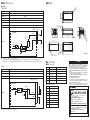
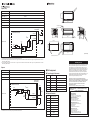
安全上の要点
形
FJ-SC5MG/S5MG
ギガビットイーサネット 500万画素デジタルカメラ
取扱説明書
このたびは、本製品をお買い上げいただきまして、
まことにありがとう
ございます。ご使用に際しては、次の内容をお守りください。
・電気の知識を有する専門家が扱ってください。
・この取扱説明書をよくお読みになり、十分にご理解のうえ、正しくご
使用ください。
・この取扱説明書はいつでも参照できるように大切に保管ください。
* 2 1 9 2 6 8 1 - 1 C *
© OMRON Corporation 2011-2015 All Rights Reserved.
安全上のご注意
●
警告表示の意味
警告
注意
●
正しい取扱いをしなければ、この危険のために、軽傷・中
程度の傷害を負ったり、万一の場合には重傷や死亡に至る
恐れがあります。また、同様に重大な物的損害をもたらす恐
れがあります。
正しい取扱いをしなければ、この危険のために、時に軽傷
・中程度の傷害を負ったり、あるいは物的損害を受ける恐れ
があります。
警告表示
警告
安全を確保する目的で直接的または間接的に人体を検出する用途
に本製品は使用できません。
人体保護用の検出装置として本製品を使用しないでください。
注意
触れると高温のため稀に火傷の恐れがあります。
通電中や電源を切った直後は、触らないでください。
製品を安全に使用するために、
以下のことを守ってください。
1. 設置場所について
次のような場所には設置しないでください。
・周囲温度が定格の範囲を超える場所
・温度変化が急激な場所(結露する場所)
・相対湿度が 35 ∼ 85%RH の範囲を超える場所
・腐食性ガス、可燃性ガスがある場所、塵埃、塩分、金属
粉がある場所
・振動や衝撃が直接加わる場所
・強い外乱光(レーザ光、
アーク溶接光など)
があたる場所
・直射日光があたる場所や暖房器具のそば
・水・油・化学薬品の飛沫がある場所
・強磁界、強電界がある場所
・高圧機器や動力機器のそば
2. 電源について
・電源は、高電圧が発生しないように対策 ( 安全超低電
圧回路 ) されている直流電源装置から供給してくださ
い。
(推奨品 オムロン
(株)製 形 S8VS-03012)
・撚り合わせただけの電線を直接端子台に接続しないで
ください。
・電源を外部から供給するときは、本書で指定した電源
電圧で使用してください。
・電源投入前に再度配線を確認してください。
・本製品は他の商品と一緒にせず、単独の電源で使用
してください。
3. 取付けについて
ねじの締め付けは確実に行ってください。
・取付けにおいて、
締め付けトルク
M3 ネジ (4 点 ):0.54N・m
・カメラの表面温度が 55℃以下となるように金属板へ取
り付けるなどしてください。
4. その他
・専用のカメラケーブル以外は使用しないでください。専用
品以外を接続して通電した場合、機器が故障し、高温
になる恐れがあります。
・本製品はストロボコントローラに対応していません。
カメラ
裏側の電源・I/O コネクタにストロボコントローラを接続し
ないでください。
・カメラ裏側の電源・I/O コネクタを使用しないときには、
コネクタについているキャップを外さないでください。
・本製品を分解したり、修理、改造しないでください。
・万一、異常を感じたときには、すぐに使用を中止し、電源
を切った上で当社支店・営業所までご相談ください。
・本製品を廃棄するときは、産業廃棄物として処理してく
ださい。
5. 法規と規格
本カメラは,以下の規格に準拠しています。
EC 指令 2004/108/EC(2016 年 4 月 19 日まで)/
EU 指令 2014/30/EU
(2016 年 4 月 20 日以降)
EN 規格(ヨーロッパ規格) EN61326-1 (Electromagnetic environment : Industrial electromagnetic
environment (EN/IEC 61326-1 Table 2))
使用上の注意
製品が動作不能、誤動作、
または性能・機器への悪影響
を防ぐため、以下のことを守ってください。
1. 電源について
・本製品は PoE に対応しておりません。
2. ケーブルについて
・着脱するときは、必ず本体の電源を切ってください。
・カメラケーブル (LAN) 形 FJ-VSG( 別売 ) をカメラに
接続するときは、
ネジ締めを確実に行ってください。
締め付けトルク:0.15N・m
・カメラケーブル ( 電源・I/O) 形 FJ-VSP( 別売 ) の
配線仕様は、後述のピンアサイン表をご参照ください。
・カメラケーブル ( 電源・I/O) 形 FJ-VSP( 別売 ) の
使用しない配線については、他の配線や機器などの影
響を受けないように処理してください。
3. 光軸について
・光軸中心がカメラごとにばらつくことがあります。取付ける
ときは必ずモニタで映像の中心位置を確認してください。
4. メンテナンスについて
・CCD 部に大きなゴミや、ホコリが付いた場合は、ブロア
ブラシ(カメラレンズ用)で吹き飛ばしてください。呼気で
吹き飛ばすことは避けてください。
・シンナー、
ベンジン、
アセトン、
灯油類は使用しないでください。
■付属品
本体、取扱説明書
(本書)
■仕様
●性能仕様
形式
形FJ-SC5MG
形FJ-S5MG
プログレッシブスキャン
2/3インチCCD
(カラー)
プログレッシブスキャン
2/3インチCCD
(モノクロ)
2454(H) x 2056(V)
2456(H) x 2058(V)
項目
撮像素子
有効画素数
画素サイズ
3.45(μm)×3.45(μm)
同期方式
内部同期
フレームレート
取込ライン数
17fps
2ライン∼2056ラインの範囲
ゲイン
シャッタスピード
29μs∼10s
映像出力
デジタル8bit
トリガ入力
外部トリガ/ソフトウェアトリガ
(イーサネット)
外部出力
I/F
レンズマウント
形式
項目
電源供給 カメラケーブル(電源・I/O)
消費電力
耐振動
①カメラケーブル (LAN) 形 FJ-VSG( 別売 ) で、カメラ裏
側のイーサネットコネクタと接続先機器のイーサネットコネク
タに接続します。
②カメラケーブル(電源・I/O)形 FJ-VSP( 別売 ) をカメ
ラ裏側の 6pin コネクタに接続します。
③カメラケーブル(電源・I/O)形 FJ-VSP( 別売 ) の
Power_+12VDC 端子と Power_GND 端子に電源を
供給します。
電源・I/Oコネクタ供給:6.4W
10∼150Hz 片振幅0.35mm
(加速度最大50m/s2)3方向(X/Y/Z) 各8分 10回
150m/s2 6方向
(上下、左右、前後)
各3回
周囲温度
周囲湿度
動作時・保存時:各35∼85%RH
(ただし、結露しないこと)
材質
腐食性ガスのないこと
IEC60529規格 IP30
ケース:亜鉛ダイキャスト(GD-ZnAl4Cu1)
ケーブル長
(LAN)
最大 40m
(形FJ-VSG
(別売)
使用時)
ケーブル長
(電源・I/O)
最大 5m
(形FJ-VSP
(別売)
使用時)
質量
ケーブル最小曲げ半径
カメラケーブル
(LAN)
形FJ−VSG
(別売)
イーサネット
コネクタ
DC11.8∼13.8V
動作時:0∼40℃
(筐体表面温度55℃以下となること)
保存時:−25∼+65℃
(ただし、氷結・結露のないこと)
保護構造
Cマウント
形FJ-SC5MG/S5MG
耐衝撃
周囲雰囲気
ストロボトリガ/トリガREADY
ギガビットイーサネット(1Gbit/s)
■接続
イーサネット
コネクタ
●一般仕様
2ライン∼2058ラインの範囲
0dB∼+14dBの範囲
約220g
FJ-VSG: 27.2mm FJ-VSP: 43.2mm
電源・I/O
コネクタ
カメラ
FJ-SC5MG/S5MG
電源装置
推奨品
カメラケーブル
(電源・
I/O) オムロン(株)製
形FJ−VSP
(別売)
形S8VS-03012
■外形寸法
■電源・I/Oインタフェース
●I/O 仕様
【入力(TRG)】
入力電圧
5
3.5 3.
さ TH
3 深DEP
4-MM3
4-
DC3.3∼24V
ON電流 ※1※2
最小2.2V
OFF電流 ※1※3
最大0.5mA
OFF電圧 ※1※3
26
最小15mA
ON電圧 ※1※2
最大1.4V
ONディレー
0.1ms以下
OFFディレー
0.1ms以下
9.7
1"-32UNF(Cマウント)6.45
1"-32UNF(C MOUNT)
取付穴加工寸法
MOUNTING SCREW HOLES
※1 ON/OFF はカメラ内部のフォトカプラの状態を示します。
※2 ON 電流 / 電圧:OFF→ON 状態にさせる電流値または電圧値のことです。ON 電圧の値は TRG 端子と I/O_GND 端子間の電位差になります。
※3 OFF 電流 / 電圧:ON→OFF 状態にさせる電流値または電圧値のことです。OFF 電圧の値は TRG 端子と I/O_GND 端子間の電位差になります。
3.5 3.
さ TH
3 深DEP
4-MM3
4-
9.7
【出力】
ご承諾事項
Pin
信号名
FJ-VSP(別売) 線色
出力電圧
DC3.3∼24V
1
Power_+12VDC
茶
負荷電流
50mA以下
2
TRG
灰
ON残留電圧 ※1
2.5V以下
3
Reserve
黒
OFF漏れ電流 ※1
0.2mA以下
4
Output
緑
5
I/O_GND
赤
6
Power_GND
青
電源・I/O コネクタ
220 Ω
3
内部回路
Output
D
BAS16
I/O_GND
負荷
4
5
6
Gnd
※1 ON/OFF はカメラ内部のフォトカプラの状態を示します。
●イーサネットコネクタ
Gnd
2
(単位:mm)
80.2
■ピンアサイン表
●電源・I/O コネクタ
1
34
5
5 .
3. Dia
5
4- -3.
4
Gnd
Q
BC847BS
15.6
15.9
15.4
14.5
26±0.2
Gnd
カメラ内部回路
13.5
5.35
80.2±0.2
180Ω
5.1k
93.15
.5
3.3 V
22
44
5 4
4. H
さ T
深 EP
2 D
M 2
2- -M
2
1
2
3
I/O_GND 4
5
6
Output
Q
BF545C
Gnd
20
26
カメラ内部回路
3.3 V
3.5
Gnd
29
電源・I/O コネクタ
内部回路
80.2
Pin
Data Signal Name
1
BI_DA+
2
BI_DA-
3
BI_DB+
4
BI_DC+
5
BI_DC-
6
BI_DB-
7
BI_DD+
8
BI_DD-
当社商品は、一般工業製品向けの汎用品として設計製造されています。従いまして、次に
掲げる用途での使用を意図しておらず、
お客様が当社商品をこれらの用途に使用される際
には、当社は当社商品に対して一切保証をいたしません。
ただし、次に掲げる用途であって
も当社の意図した特別な商品用途の場合や特別の合意がある場合は除きます。
(a) 高い安全性が必要とされる用途
(例:原子力制御設備、燃焼設備、航空・宇宙設備、鉄
道設備、昇降設備、娯楽設備、医用機器、安全装置、
その他生命・身体に危険が及び
うる用途)
(b) 高い信頼性が必要な用途
(例:ガス・水道・電気等の供給システム、24時間連続運転
システム、決済システムほか権利・財産を取扱う用途など)
(c) 厳しい条件または環境での用途
(例:屋外に設置する設備、化学的汚染を被る設備、
電磁的妨害を被る設備、振動・衝撃を受ける設備など)
(d) カタログ等に記載のない条件や環境での用途
*(a)から(d)に記載されている他、本カタログ等記載の商品は自動車
(二輪車含む。以下同
じ)
向けではありません。自動車に搭載する用途には利用しないで下さい。自動車搭載
用商品については当社営業担当者にご相談ください。
*上記は適合用途の条件の一部です。当社のベスト、総合カタログ、データシート等最新版
のカタログ、
マニュアルに記載の保証・免責事項の内容をよく読んでご使用ください。
インダストリアルオートメーションビジネスカンパニー ●製品に関するお問い合わせ先
お客様相談室
0120-919-066
クイック
オムロン
携帯電話・PHS・IP電話などではご利用いただけませんので、下記の電話番号へおかけください。
電話
055-982-5015(通話料がかかります)
■営業時間:8:00∼21:00 ■営業日:365日
●FAXやWebページでもお問い合わせいただけます。
FAX
055-982-5051 / www.fa.omron.co.jp
●その他のお問い合わせ
納期・価格・サンプル・仕様書は貴社のお取引先、または貴社
担当オムロン販売員にご相談ください。
オムロン制御機器販売店やオムロン販売拠点は、Webページで
ご案内しています。
A v 2 0 1 4 年 7月
PRECAUTIONS FOR SAFE USE
Model
FJ-SC5MG/S5MG
Gigabit Ethernet 5.0 Megapixel Digital Camera
INSTRUCTION SHEET
Thank you for selecting OMRON product. This sheet primarily describes precautions required in installing and
operating the product.
Before operating the product, read the sheet thoroughly to
acquire sufficient knowledge of the product. For your convenience, keep the sheet at your disposal.
TRACEABILITY INFORMATION:
Importer in EU:
Manufacturer:
Omron Europe B.V.
Omron Corporation,
Wegalaan 67-69
Shiokoji Horikawa, Shimogyo-ku,
2132 JD Hoofddorp,
Kyoto 600-8530 JAPAN
The Netherlands
The following notice applies only to products that carry the CE mark:
Notice:
This is a class A product. In residential areas it may cause radio
interference, in which case the user may be required to take adequate
measures to reduce interference.
* 2 1 9 2 6 8 1 - 1 C *
© OMRON Corporation 2011-2015 All Rights Reserved.
PRECAUTIONS ON SAFETY
Indicates a potentially hazardous situation which, if
avoided, will result in minor or moderate injury,
WARNING not
or may result in serious injury or death. Additionally
there may be significant property damage.
CAUTION
Indicates a potentially hazardous situation which, if
not avoided, may result in minor or moderate injury
or in property damage.
WARNING
This product is not designed or rated for ensuring
safety of persons. Do not use it for such purposes.
CAUTION
Burn injury may occasionally occur.
Do not touch while operating and immediately after
turn-off.
Be sure to respect following items for safety.
1. Installation Site
Do not install the product in locations subjected to the
following conditions:
• Ambient temperature outside the rating
• Rapid temperature fluctuations (causing condensation)
• Relative humidity outside the range of 35 to 85%
• Presence of corrosive or flammable gases
• Presence of dust, salt, or metallic particles
• Direct vibration or shock
• Reflection of intense light (such as other laser beams or
electric arc-welding machines)
• Direct sunlight or near heaters
• Water, oil, or chemical fumes or spray
• Strong magnetic or electric field
• Near high-voltage equipment or power equipment
2. Power Supply
• Supply power from a DC power supply that prevents
the occurrence of high voltage (safety ultra-low voltage
circuit). (Recommended product: S8VS-03012
(OMRON))
• Do not directly connect the merely twisted wires to terminals.
• Be sure to use the power supply according to the power
supply voltage specified in this manual when supplying
power externally.
• Be sure to check wiring again before turning on power.
• Be sure to use an individual power supply for the product.
Do not share the power supply with other products.
3. Mounting the Camera
• Be sure to tighten screws firmly for mounting.
Tightening torque:
M3 screw x 4: 0.54 N×m
• Mount the Camera to a metal plate to keep the surface
temperature of the Camera to be 55°C or less.
PRECAUTIONS FOR CORRECT USE
Observe the precautions described below to prevent
operation failure, malfunctions, or undesirable effects on
product performance.
1. Power supply
• This product does not conform to PoE.
2. Connecting Cables
• Be sure to turn off the power before disconnecting the
cables.
• Be sure to tighten screws firmly when connecting
Camera cable (LAN) FJ-VSG (sold separately) to the
Camera.
Tightening torque: 0.15 N×m
• For information on specifications of Camera cable
(power supply, I/O) FJ-VSP (sold separately), see the
pin assignment table described later.
• When not using the Camera cable (power supply, I/O)
FJ-VSP (sold separately), perform wiring so as not to be
affected by other wiring or devices.
3. Optical axis of the Camera
• The center of the optical axis varies with the Camera
used. Therefore, when installing the Camera, always
check the center of the image displayed on the monitor.
4. Maintenance
• If large dust particles adhere to the CCD, use a blower
brush (used to clean Camera lenses) to blow them off.
Do not blow the dust particles with your mouth.
• Do not use thinners, benzene, acetone, or kerosene to
clean Camera.
Main unit, instruction sheet (this manual)
4. Others
• Use only the dedicated camera cable. If the device is
turned on with the non-dedicated product connected,
the device may be damaged, causing high temperature.
• This product does not support strobe controller. Do not
connect a strobe controller to the connector for power
supply and I/O connector on the back of the Camera.
• When power supply or I/O connector on the back of the
Camera is not used, do not remove the cap attached to
the connector.
• Do not try to disassemble, repair, or modify this
product.
• When an abnormal condition occurs, immediately stop
operation and turn off the product. Contact an
OMRON's local office or sales office.
• When disposing the product, dispose it as industrial waste.
Item
5. Regulations and Standards
• This Camera conforms to the following standards.
• EC Directive, 2004/108/EC (Until April 19, 2016) /
EU Directive, 2014/30/EU (From April 20, 2016)
• EN Standard (European standard) EN61326-1
(Electromagnetic environment : Industrial electromagnetic
environment (EN/IEC 61326-1 Table 2))
• Regulation of KC marking
A급 기기(업무용 방송통신기자재)
이 기기는 업무용(A급) 전자파적합기기로서 판매자
또는 사용자는 이 점을 주의하시기 바라며,가정외의
지역에서 사용하는 것을 목적으로 합니다.
Ambient
environment
Model
Power Camera cable
delivery (power supply, I/O)
Power
consumption
FJ-SC5MG/S5MG
11.8 to 13.8 VDC
10 to 150 Hz: half-amplitude: 0.35 mm:
(maximum acceleration: 50 m/s2),
10 times each in X, Y, and Z directions for 8 min
Shock
resistance
150 m/s2, 3 times each in 6 directions
(up/down, left/right, forward/backward)
Ambient
humidity
Operating: 0 to 40°C
(The surface temperature of the case must be 55°C max.)
(with no icing or condensation)
Storage: -25 to 65°C
(with no icing or condensation)
Operating and storage: 35% to 85%
(with no condensation)
No corrosive gases
Degree of
protection
IEC60529 IP30
Materials
Case: Zinc die-cast (GD-ZnA14Cu1)
Cable length (LAN)
40 m max. (using FJ-VSG(sold separately))
Cable length
(power supply, I/O)
5 m max. (using FJ-VSP(sold separately))
Weight
Minimum cable
bending radius
FJ-SC5MG
FJ-S5MG
Picture
element
Progressive scan CCD
2/3-inch CCD (monochrome)
Effective
pixels
2454 (H) x 2056 (V)
2456 (H) x 2058 (V)
Pixel size
Synchronization
3.45 (μm) x 3.45 (μm)
Internal sync.
Frame rate
Number of lines
to be read
Gain
17 fps
2 lines to 2056 lines
2 lines to 2058 lines
0 dB to 14 dB
Shutter speed
29 μs to 10 s
Video output
Digital (8 bits)
Trigger input
External trigger/software trigger (Ethernet)
External output
Stroboscopic trigger/trigger ready
I/F
Lens mounting
Gigabit Ethernet (1 Gbit/s)
C mount
(1) Using the Camera cable (LAN) FJ-VSG (sold
separately), connect the connector on the back of the
Camera and the Ethernet connector of a device to be
connected.
(2) Connect the Camera cable (power supply, I/O) FJ-VSP
(sold separately) to the 6-pin connector on the back of
the Camera.
(3) Supply power to the Power_+12 VDC terminal and
Power_GND terminal of the Camera cable (power
supply, I/O) FJ-VSP (sold separately).
Ethernet
connector
Camera cable (LAN) FJ-VSG
(sold separately)
Ethernet
connector
Power supply, I/O connector: 6.4 W
Vibration
resistance
Ambient
Temperature
Model
Progressive scan CCD
2/3-inch CCD (color)
Item
Approx. 220 g
FJ-VSG: 27.2 mm
FJ-VSP: 43.2mm
Power supply,
Recommended
I/O connector
power supply:
Camera
FJ-SC5MG/S5MG Camera cable (power supply, I/O) S8VS-03012
(OMRON)
FJ-VSP (sold separately)
Inputs (TRG)
3.3 to 24 VDC
ON current *1, *2
2.2 V min.
OFF current *1, *3
0.5 mA max.
OFF voltage *1, *3
1.4 V max.
OFF delay
0.1 ms max.
9.7
1"-32UNF(C MOUNT)
Camera internal circuit
93.15
13.5
5.35
TH
EP
34
D
4.
80.2±0.2
26
Gnd
26±0.2
180Ω
5
3.3 V
22
44
2
3.3 V
5.1k
20
M
Internal circuit
3.5
2-
1
2
3
I/O_GND 4
5
6
Output
Q
BF545C
6.45
Gnd
14.5
Power supply,
I/O connector
80.2
15.9
15.4
0.1 ms max.
29
ON delay
3.5
26
15 mA min.
ON voltage *1, *2
H
PT
DE
15.6
Input voltage
3
4-M
45D
3.
ia
3.5
9.7
4-
.
Gnd
TH
EP
D
M3
80.2
(Unit: mm)
MOUNTING SCREW HOLES
*1 ON/OFF indicates the status of the photocoupler installed inside the Camera.
*2 ON current/ON voltage indicates the current value or voltage value to be turned OFF to ON. The value of ON voltage is the potential difference between the
TRG and I/O_GND terminals.
*3 ON current/ON voltage indicates the current value or voltage value to be turned ON to OFF. The value of OFF voltage is the potential difference between the
TRG and I/O_GND terminals.
Suitability for Use
Outputs
■ Pin Assignment
3.3 to 24 VDC
Output voltage
Load current
50 mA max.
ON residual voltage *1
2.5 V max.
OFF leakage current *1
0.2 mA max.
● Power Supply, I/O Connector
Power supply,
I/O connector
Camera internal circuit
1
Q
BC847BS
220 Ω
Gnd
2
3
Internal circuit
Output
Gnd
D
BAS16
I/O_GND
Load
4
5
6
Gnd
*1 ON/OFF indicates the status of the photocoupler installed inside the Camera.
Pin
Signal name
FJ-VSP (sold separately) wire color
1
Power_+12 VDC
Brown
2
TRG
Gray
3
Reserve
Black
4
Output
Green
5
I/O_GND
Red
6
Power_GND
Blue
● Ethernet Connector
Pin
Data Signal Name
1
BI_DA+
2
BI_DA-
3
BI_DB+
4
BI_DC+
5
BI_DC-
6
BI_DB-
7
BI_DD+
8
BI_DD-
Omron Companies shall not be responsible for conformity with any standards,
codes or regulations which apply to the combination of the Product in the
Buyer’s application or use of the Product. At Buyer’s request, Omron will
provide applicable third party certification documents identifying ratings and
limitations of use which apply to the Product. This information by itself is not
sufficient for a complete determination of the suitability of the Product in
combination with the end product, machine, system, or other application or
use. Buyer shall be solely responsible for determining appropriateness of the
particular Product with respect to Buyer’s application, product or system.
Buyer shall take application responsibility in all cases.
NEVER USE THE PRODUCT FOR AN APPLICATION INVOLVING
SERIOUS RISK TO LIFE OR PROPERTY WITHOUT ENSURING THAT THE
SYSTEM AS A WHOLE HAS BEEN DESIGNED TO ADDRESS THE RISKS,
AND THAT THE OMRON PRODUCT(S) IS PROPERLY RATED AND
INSTALLED FOR THE INTENDED USE WITHIN THE OVERALL
EQUIPMENT OR SYSTEM.
See also Product catalog for Warranty and Limitation of Liability.
OMRON Corporation
Tokyo, JAPAN
Industrial Automation Company
Contact: www.ia.omron.com
Regional Headquarters
OMRON EUROPE B.V.
Sensor Business Unit
Carl-Benz-Str. 4, D-71154 Nufringen, Germany
Tel: (49) 7032-811-0/Fax: (49) 7032-811-199
OMRON ELECTRONICS LLC
2895 Greenspoint Parkway, Suite 200
Hoffman Estates, IL 60169 U.S.A.
Tel: (1) 847-843-7900/Fax: (1) 847-843-7787
OMRON ASIA PACIFIC PTE. LTD.
No. 438A Alexandra Road # 05-05/08 (Lobby 2),
Alexandra Technopark,
Singapore 119967
Tel: (65) 6835-3011/Fax: (65) 6835-2711
OMRON (CHINA) CO., LTD.
Room 2211, Bank of China Tower,
200 Yin Cheng Zhong Road,
PuDong New Area, Shanghai, 200120, China
Tel: (86) 21-5037-2222/Fax: (86) 21-5037-2200
D s Oct , 2014
型号
FJ-SC5MG/S5MG
千兆以太网 500万像素数码相机
使用说明书
首先,非常感谢您选择使用本产品。
使用本产品时,请务必遵守以下事项。
・请具有电气知识的专业人员进行操作。
・请仔细阅读本使用说明书,并在充分理解的基础上加以使用。
・请妥善保管本使用说明书,以便使用时参考。
安全要领
使用注意事项
为了确保产品的安全使用,请务必遵守以下事项。
为了防止产品无法作业、误动作、或对性能 ・ 设备产
生不良影响,请务必遵守以下事项。
1. 关于设置场所
请勿在以下场所使用。
・周围温度超出额定温度范围的场所
・温度骤变的场所(结露场所)
・相对湿度超出 35 ~ 85%RH 范围的场所
・有腐蚀性气体、可燃性气体、以及灰尘 ・ 盐分 ・ 金
属粉的场所
・易受直接振动或撞击的场所
・有强烈环境光线(激光、电焊光等)的场所
・阳光直射处或加热设备附近
・水、油、化学药品飞溅的场所
・有强磁场、强电场的场所
・高压设备或电力设备的附近
2. 关于电源
・供电设备请使用具有防止高电压发生功能(安全超
低电压电路)的直流电源装置。
(推荐产品 欧姆龙
( 株 ) 生产 型号 S8VS-03012)
・配线请使用无焊接头。请勿将只经过绞合的电线直
接连接至接线排。
・由外部供电时,请使用本手册指定的电源电压。
・接通电源前请重新接线并加以确认。
・本产品使用独立电源,请勿与其他商品一起使用。
* 2 1 9 2 6 8 1 - 1 C *
© OMRON Corporation 2011-2015 All Rights Reserved.
安全注意事项
● 警告标示的含义
警告
注意
表示若操作不当,则可能会因此危险状况而导致轻伤 ・
中等程度的伤害、甚至重大伤亡事故的发生。同时,还
可能造成严重的财产损失。
表示若操作不当,则可能会因此危险状况而导致轻伤 ・
中等程度的伤害、或者造成严重的财产损失。
● 警告标示
警告
为了确保安全,本产品不可直接或间接地用于人体检查。请勿
将本产品作为人体保护检测装置使用。
注意
请勿触碰,否则可能会因高温而导致少有的烧伤事故。
通电中或刚切断电源后请勿触碰。
3. 关于安装
・安装时请务必要紧固螺钉。
紧固转矩
M3 螺钉 (4 点 ):0.54N・m
・请安装于金属板上等,以使相机表面温度保持在
55℃以下。
4. 其他
・请勿使用专用相机电缆以外的电缆。连接至专用以
外的电缆且接通电源时,可能会导致设备故障、并产
生高温。
・本产品不适用于频闪控制器。请勿将频闪控制器连
接在相机背面的电源 ・I/O 接口上。
・不使用相机背面的电源 ・I/O 接口时,请勿取下接口
上的防护盖。
・请勿擅自对本产品进行拆卸、修理、改造。
・万一感到异常时,请立即停止使用并切断电源,然后
联系本公司支店 ・ 营业所。
・对本产品进行废弃处理时,请作为工业废弃物加以
处理。
1. 关于电源
本产品不适用于 PoE。
2. 关于电缆
・装卸时请务必切断主机电源。
・将 FJ-VSG 型 ( 另售 ) 相机电缆连接至相机时,请务
必进行螺钉紧固。
紧固转矩:0.15N・m
・FJ-VSP 型 ( 另售 ) 相机电缆(电源 ・I/O)的配线规
格请参照后述的引脚分配表。
・对于不使用 FJ-VSP 型 ( 另售 ) 相机电缆(电源 ・
I/O)的配线,处理时请注意不要受到其他配线或设备
等的影响。
3. 关于光轴
・光轴中心在各台相机上均有所差异。安装时请务必
通过显示屏确认图像的中心位置。
4. 关于维护
・CCD 部位大面积附着垃圾、灰尘时,请使用吹气刷
(相机镜头用)吹去。请勿使用呼气吹。
・请勿使用稀释剂、汽油、丙酮、灯油类物品。
■附属品
●性能规格
型号
型号FJ-SC5MG
型号FJ-S5MG
摄像元件
逐行扫描
2/3英寸CCD(彩色)
逐行扫描
2/3英寸CCD(单色)
有效像素
2454(H)×2056(V)
2456(H)×2058(V)
项目
像素尺寸
3.45(μm) × 3.45(μm)
同步方式
内同步
帧速
读入线数
增益
快门速度
2线 ~ 2058线的范围
0dB ~ +14dB的范围
29μs ~ 10s
图像输出
数码8bit
触发输入
外部触发/软件触发(以太网)
外部输出
I/F
频闪触发/触发READY
千兆以太网(1Gbit/s)
镜头卡口
C卡口
■连接
①通过 FJ-VSG 型号(另售)的相机电缆(LAN)
,将相机
背面的以太网接口与连接对象设备的以太网接口相
互连接。
②将 FJ-VSP 型号(另售)的相机电缆(电源 ・I/O)连接
至相机背后的 6pin 接口上。
③向 FJ-VSP 型号(另售)的相机电缆(电源 ・I/O)的
Power_+12VDC 接头及 Power_GND 接头供电。
主机、使用说明书(本手册)
以太网接口
■规格
17fps
2线 ~ 2056线的范围
相机电缆(LAN)型号FJ-VSG(另售)
以太网接口
●一般规格
型号
项目
电力供应 相机电缆(电源・I/O)
消费电力
耐振动
耐冲击
型号FJ-SC5MG/S5MG
DC11.8~13.8V
电源・I/O接口供给:6.4W
10~150Hz 单振幅0.35mm
(最大加速50m/s2)3方向(X/Y/Z) 各8分钟 10次
150m/s2 6方向(上下、左右、前后) 各3次
周围温度
工作时:0~40℃(机箱表面温度应在55℃以下)
保存时:-25~+65℃
(但是,不得结冰・结露)
5. 法规及规格
本相机以以下规格为标准
EC Directive, 2004/108/EC (Until April 19, 2016) /
EU Directive, 2014/30/EU(From April 20, 2016)
EN 规格(欧洲规格) EN61326-1 周围湿度
工作时・保存时:均为35~85%RH
(但是,不得结露)
(Electromagnetic environment : Industrial electromagnetic
environment (EN/IEC 61326-1 Table 2))
电缆长度(LAN)
周围环境
不得有腐蚀性气体
保护结构
IEC60529规格 IP30
材质
电缆长度(电源•I/O)
重量
电缆最小弯曲半径
遮罩:铝合金
机盒:锌合金压铸(GD-ZnAl4Cu1)
最长 40m(使用型号FJ-VSG(另售)时)
最长 5m(使用型号FJ-VSP(另售)时)
约220克
FJ-VSG: 27.2mm FJ-VSP: 43.2mm
电源・I/O接口
相机
FJ-SC5MG/S5MG
相机电缆(电源・I/O)
型号FJ-VSP(另售)
电源装置推荐品 欧姆龙(株)制
型号S8VS-03012
■外形尺寸
■电源・I/O接口
●I/O 规格
【输入(TRG)】
输入电压
.5 5
度3 H 3.
3 深 EPT
4-M 3 D
4-M
DC3.3~24V
ON电流※1※2
最小2.2V
OFF电流※1※3
最大0.5mA
OFF电压 ※1※3
26
最小15mA
ON电压 ※1※2
最大1.4V
ON延迟
0.1ms以下
OFF延迟
0.1ms以下
9.7
1"-32UNF(C卡口)
1"-32UNF(C MOUNT)
6.45
3.5
20
Gnd
180Ω
5.1k
Gnd
15.9
15.4
5 .
3. Dia
5
4- -3.
4
Gnd
安装孔加工尺寸
MOUNTING SCREW HOLES
※1 ON/OFF 表示相机内部光电耦合器的状态。
※2 ON 电流 / 电压:将 OFF→转换为 ON 状态的电流值或电压值。ON 电压的值为 TRG 接头与 I/O_GND 接头之间的电位差。
※3 OFF 电流 / 电压:将 ON→转换为 OFF 状态的电流值或电压值。OFF 电压的值为 TRG 接头与 I/O_GND 接头之间的电位差。
5.35
13.5
34
26
3.3 V
93.15
80.2±0.2
26±0.2
3.3 V
22
44
5 .5
4. 4
度 TH
深 P
2 E
M 2D
2- -M
2
1
2
3
I/O_GND 4
5
6
Output
Q
BF545C
内部电路
14.5
相机内部电路
15.6
29
电源 ・I/O 接口
80.2
.5 5
度3 H 3.
3 深 EPT
4-M 3 D
4-M
9.7
80.2
(单位:mm)
■引脚分配表
●电源 ・I/O 接口
【输出】
输出电压
DC3.3~24V
负荷电流
50mA以下
ON剩余电压 ※1
2.5V以下
OFF泄漏电流 ※1
0.2mA以下
电源 ・I/O 接口
相机内部电路
1
Q
BC847BS
220 Ω
Gnd
内部电路
Output
Gnd
D
BAS16
I/O_GND
负荷
4
5
6
Gnd
※1 ON/OFF 表示相机内部光电耦合器的状态。
信号名称
FJ-VSP(另售)电线颜色
1
Power_+12VDC
茶色
2
TRG
灰色
3
Reserve
黑色
4
Output
绿色
5
I/O_GND
红色
6
Power_GND
蓝色
●以太网接口
2
3
Pin
Pin
Data Signal Name
1
BI_DA+
2
BI_DA-
3
BI_DB+
4
BI_DC+
5
BI_DC-
6
BI_DB-
7
BI_DD+
8
BI_DD-
q