1
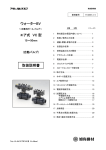
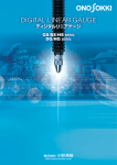
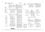
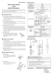
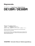
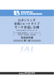
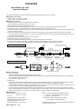
AA-6100/6101 Air Lifter
Instruction Manual
This product is dedicated for the GS-1513A/1530A/1613A/1630A linear gauge sensor from Ono Sokki.
● Applicable Linear Gauges
AA-6100 air lifter : GS-1513A, GS-1613A
AA-6101 air lifter : GS-1530A, GS-1630A
●Installation Procedure
*When using a tool, be careful not to tighten screws excessively.
(Do not provide the torsional force which is over 0.3Nm.)
*Apply adhesive agent to prevent loosening of screws.
(1) Remove the cap from the linear gauge sensor. In this case, leave the O-ring inside the cap attached on the sensor side.
(2) Screw the mounter 1 to the female screw from which the cap was removed, then secure it firmly.
(3) Screw the set-screw 2 (cap screw) into the air port hole (M5 female screw) of the air lifter 3 so that the joint pin 4 be pushed out from
the other side of the air lifter.
(4) Push in the spindle of the linear gauge sensor and then screw the joint pin 4 into the M2.5 female screw at the top of the spindle.
You can do this with your fingers but the use of a tool is recommended. Note that excessive application of adhesive agent to the joint pin
4 may affect sensor operation.
(5) Screw the air lifter 3 into the M8 male screw of the mounter 1.
(6) Remove the set-screw 2 (cap screw) slowly.
(7) Attach the supplied speed controller to the air port hole (M5 female screw) of the air lifter 3.
(8) At the time when the above installation is complete, the spindle of the linear gauge sensor is being compressed.
When the air is supplied from the speed controller, the spindle will be expanded by the spring built in the sensor.
Cap
Air Lifter Configuration
2 Set-screw (cap screw)
Linear gauge sensor
4 Joint pin
M2.5 female screw
Spindle
M8 male screw
O-ring
Air port hole (M5 female screw)
M8 male screw
1 Mounter
3 Air lifter
Speed controller
Example Air Plumbing Configuration
AA-6100/6101
(SSU4/Koganei)
Three-way
( )
electromagnetic valve
●Notes on Operation
(1) Notes on air supply
・ Adjust the operating speed of the spindle with the speed controller.
Excessive operating speed may damage the object under measurement. If the spindle speed exceeds the maximum response speed,
error indication is made on the counter.
・ Use an air filter to supply clean air.
(2) Other notes
・ To adjust the return speed of the spindle, attach an exhaust throttle valve (SSU4/Koganei) as close to the speed controller as possible.
・ Be careful not to get water or oil directly in the hole at the center of the air lifter. (IP64 is not applied to the air lifter.)
・ If adhesive agent is applied excessively to prevent loosening of screws, it may come inside the bearing, resulting in malfunction of the air
lifter. Use caution to the mount of adhesive agent and the positions to apply it.
・ In case the cylinder is used for the first time after a long unused period or in a cold environment, it may take a little while until it works
after the electromagnetic valve operates, or the cylinder may start to work suddenly, losing control of the speed because of the structure
of the air cylinder itself. Be sure to make a test operation before you use the cylinder for a measurement.
●Specifications
Operating range : AA-6100 : 0 to 13mm
AA-6101 : 0 to 30mm
Fluid : Air
Operating pressure : 0.25 to 0.7MPs
Guaranteed pressure resistance : 0.9MPs
Operating temperature : 0 to +40 ℃
Storage temperature : -10 to +55 ℃
ONO SOKKI CO., LTD.
Mass : AA-6100 : 40g (including the speed controller)
AA-6101 : 50g (including the speed controller)
Life expectancy : 5,000,000 times
Accessories : Mounter, speed controller, set-screw
(Speed controller : Koganei/SS4-M5B)
* Standards, specifications, and external appearance are subject to
change without prior notice.
AA-6100/6101 エアーリフタ
取扱説明書
本製品は、当社リニアゲージセンサGS-1513A,1530A,1613A,1630A専用のエアーリフタです。
●適合リニアゲージ
AA-6100型エアーリフタ:GS-1513A, GS-1613A
AA-6101型エアーリフタ:GS-1530A, GS-1630A
●取付方法
*工具を使用する場合、ねじ部の締め込み過ぎに注意してください。
(0.3 Nmを超えるようなねじれ力が、加わらないようにしてください)
*ねじ部にゆるみ止め用の接着剤を使用してください。
(1) リニアゲージセンサのキャップを取り外します。
その際、キャップの内側に入っているOリングはセンサ側に残しておいてください。
(2) キャップを取り外したネジ部に1マウンターをねじ込んで固定します。
(3) 3エアリフタのエアポート穴(M5雌ねじ)に2押しねじ(キャップねじ)をねじ込んで4ジョイントピンを押し出します。
(4) リニアゲージセンサのスピンドルを押し込み、スピンドル上端のねじ(M2.5雌ねじ)に4ジョイントピンをねじ込みます。
指でもねじ込めますが、工具を使用することをお奨めします。
4ジョイントピンに接着剤を塗布し過ぎますと、センサの動きに影響が出ることがありますのでご注意ください。
(5) 1マウンターのねじ部(M8雄ねじ)に3エアリフタをねじ込みます。
なお、ねじ込み過ぎはスピンドルの動きを悪くしますのでご注意ください。
(6) 2押しねじを(キャップねじ)をゆっくり外します。
(7) 付属のスピードコントローラを3エアリフタのエアポート穴(M5雌ねじ)に固定します。
(8) 以上の取付が完了すると、リニアゲージセンサのスピンドルは縮んだ状態になっています。
スピードコントローラからエアを供給すると、スピンドルはリニアゲージセンサに内蔵されているバネの力で元の長さに戻ります。
キャップ
エアリフタ構成図
リニアゲージセンサ
2 押しねじ (キャップねじ)
4 ジョイントピン
エアポート穴 (M5 めねじ)
M2.5 めねじ
スピンドル
M8 おねじ
Oリング
M8 おねじ
1 マウンター
3 エアリフター
スピードコントローラ
エア配管図(例)
AA-6100/6101
(SSU4/コガネイ)
推奨電磁弁
( )
●運転上のご注意
030E1/コガネイ
(1) エア供給時
・スピンドルの動作速度はスピードコントローラで調整してください。
速すぎると被測定物を傷つけます。また、スピンドルが最大応答速度を超えると、カウンタにエラーが表示されます。
・エアフィルタを使用してきれいな空気を供給してください。
(2) その他
・スピンドルの戻り速度を調整する場合はスピードコントローラの出来るだけ近くに排気絞り弁(SSU4/コガネイ)を付けて動きを調整
してください。
・エアリフタの中央部分に開いている穴に、直接水や油がかからないようにしてください(エアリフタはIP64の対象外になります)。
・ゆるみ防止のための接着剤を多量に使用した場合に、軸受け内部に侵入して動作不良の原因となることがあります。
接着剤は塗布量や塗布する箇所に十分に注意してください。
・エアシリンダの構造上 、長時間停止した後や寒冷な環境の場合に、暫くは電磁弁がONしてから作動するまでのレスポンスが悪いこと
があります。また、動き出す時には急に飛び出して速度コントロールが効かない可能性がありますので、測定の前には試運転を行って
ください。
●仕様
動 作 範 囲 :AA-6100/0∼13mm
AA-6101/0∼30mm
使 用 流 体 :空気
使 用 圧 力 :0.25∼0.7MPa
保 証 耐 圧 力 :0.9MPa
使用温度範囲:0∼+40℃
保存温度範囲:−10∼+55℃
質 量:AA-6100/40g(スピードコントローラを含む)
AA-6101/50g(スピードコントローラを含む)
寿 命:500万回
付 属 品:マウンター、スピードコントローラ、押しねじ
(スピードコントローラ:コガネイ/SS4-M5B)
※規格、仕様および外観は改良のため予告なく変更することが
あります。
B00000883 / IM98030202(4) ,011(MS)1.5H