1
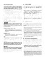
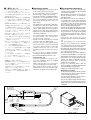
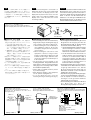
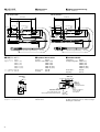
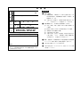
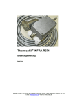
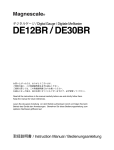
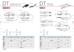
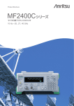
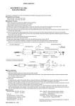
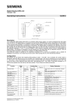
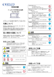
デジタルゲージ / Digital Gauge / Digitalmeßsonde
DT12N / DT12P
DT512N / DT512P
お買い上げいただき、ありがとうございます。
ご使用の前に、この取扱説明書を必ずお読みください。
この取扱説明書は、シリアルNo. 300001∼用です。
ご使用に際しては、この取扱説明書どおりお使いください。
お読みになった後は、後日お役に立つこともございますので、必ず保管してください。
Read all the instructions in the manual carefully before use and strictly follow them.
Keep the manual for future references.
Lesen Sie die ganze Anleitung vor dem Betrieb aufmerksam durch und folgen Sie beim
Betrieb des Geräts den Anweisungen. Bewahren Sie diese Bedienungsanleitung zum
späferen Nachlesen griffbereit auf.
取扱説明書 / Instruction Manual / Bedienungsanleitung
第1版 (改訂3) / 1st Edition (Revised 3) / 1.Auflage (Version 3)
Serial No. 300001 and Higher
[For U.S.A. and Canada]
■ 一般的な注意事項
THIS CLASS A DIGITAL DEVICE COMPLIES WITH
PART15 OF THE FCC RULES AND THE CANADIAN
ICES-003. OPERATION IS SUBJECT TO THE
FOLLOWING TWO CONDITIONS.
(1) THIS DEVICE MAY NOT CAUSE HARMFUL
INTERFERENCE, AND
(2) T H I S D E V I C E M U S T A C C E P T A N Y
INTERFERENCE RECEIVED, INCLUDING
INTERFERENCE THAT
MAY CAUSE UNDERSIGNED OPERATION.
以下は当社製品を正しくお使いいただくための一般的注意事
項です。個々の詳細な取扱上の注意は、本取扱説明書に記述
された諸事項および注意をうながしている説明事項に従って
ください。
CET APPAREIL NUMERIQUE DE LA CLASSE A
EST CONFORME A LA NORME NMB-003 DU
CANADA.
[ For EU and EFTA countries ]
CE Notice
Making by the symbol CE indicates compliance of the
EMC directive of the European Community. Such
marking is indicative meets of exceeds the following
technical standards.
EN 55011 Group 1 Class A / 91 :
"Limits and methods of measurement of
electromagnetic disturbance characteristics of
industrial, scientific and medical (ISM) radio-frequency
equipment"
EN 50082-2 / 95:
"Electromagnetic compatibility - Generic immunity
standard Part 2 : Industrial environment"
警告
本装置を機械指令 (EN 60204-1) の適合を受ける機器
にご使用の場合は、その規格に適合するように方策
を講じてから、ご使用ください。
Warning
When using this device with equipment governed by
Machine Directives EN 60204-1, measures should be
taken to ensure conformance with those directives.
Warnung
Wenn dieses Gerät mit Ausrüstungsteilen verwendet
wird, die von den Maschinenrichtlinien EN 60204-1
geregelt werden, müssen Maßnahmen ergriffen
werden, um eine Übereinstimmung mit diesen
Normen zu gewährleisten.
• 始業または操作時には、当社製品の機能および性能が正常
に作動していることを確認してからご使用ください。
• 当社製品が万一故障した場合、各種の損害を防止するため
の充分な保全対策を施してご使用ください。
• 仕様に示された規格以外での使用または改造を施された製
品については、機能および性能の保証は出来ませんのでご
留意ください。
• 当社製品を他の機器と組合わせてご使用になる場合は、使
用条件、環境などにより、その機能および性能が満足され
ない場合がありますので、充分ご検討の上ご使用くださ
い。
■ General precautions
When using Sony Precision Technology products, observe
the following general precautions along with those given
specifically in this manual to ensure proper use of the
products.
• Before and during operations, be sure to check that our
products function properly.
• Provide adequate safety measures to prevent damages
in case our products should develop malfunctions.
• Use outside indicated specifications or purposes and
modification of our products will void any warranty of the
functions and performance as specified of our products.
• When using our products in combination with other
equipment, the functions and performances as noted in
this manual may not be attained, depending on operating
and environmental conditions.
■ Allgemeine Vorsichtsmaßnahmen
Beachten Sie bei der Verwendung von Sony Precision
Technology Produkten die folgenden allgemeinen sowie die
in dieser Bedienungsanleitung besonders
hervorgehobenen Vorsichtsmaßnahmen, um eine
sachgerechte Behandlung der Produkte zu gewährleisten.
• Vergewissern Sie sich vor und während des Betriebs,
daß unsere Produkte einwandfrei funktionieren.
• Sorgen Sie für geeignete Sicherheitsmaßnahmen, um im
Falle von Gerätestörungen Schäden auszuschließen.
• Wenn das Profukt modifiziert oder nicht seinem Zweck
entsprechend verwendet wird, erlischt die Garantie für
die angegebenen Funktionen und Leistungsmerkmale.
• Bei Verwendung unserer Produkte zusammen mit
Geräten anderer Hersteller werden je nach den
Umgebungsbedingungen die in der Bedienungsanleitung
beschriebenen Funktionen und Leistungsmerkmale
möglicherweise nicht erreicht.
■ ご使用にあたって
■ Operating Cautions
■ Zur besonderen Beachtung
• 特に強力な磁気が発生するものは、測長ユニ
ットから10 cm以上離してください。
• ケーブルを強く引っ張ったり、ケーブルをつ
かんでの取り付けや取り外しを行いますと断
線の恐れがあります。
• DT12P, DT512Pには防塵ベローズが標準装着
されておりますが、完全防水型ではありませ
ん。直接水や油がかからないようにご使用く
ださい。
• DT12N, DT512Nはスピンドル部分が防水、防
塵構造ではありませんので、スピンドル部分
には直接水や油がかからないようにご使用く
ださい。スピンドルの汚れは動作不良の原因
となります。汚れがついた場合は、乾いた布
で拭き取ってください。
• 測定子のねじ込みトルクは、0.05 ∼ 0.06 N・m
を目安として締め付けてください。
なお、測定子ゆるみ防止のため、呼び2.5のス
プリングワッシャをはさむか、ねじロックの
ご使用をおすすめします。
• DTシリーズは、表示ユニットLT10, LT11シリ
ーズとセットでご使用ください。他の表示ユ
ニットとは直接接続できません。
• エアーリフタDZ176(別売)を使用することによ
り、スピンドルに直接手を触れずにエア駆動
で測定ができます。測長ユニット上部にある
キャップ(図1)を外し、エアーリフタをねじ込
んでください。
• コネクタ着脱は、必ず表示ユニットの電源が
入っていない状態で行ってください。
• キャリブレーションは 1 年毎に行なってくだ
さい。
• 付属のフェライトコアについて
他の機器からのノイズによる誤動作を防止す
るため、付属のフェライトコアをケーブルに
装着してご使用ください。
装着は表示ユニット (受信) 側にもっとも近い
位置にしっかりと固定してください。
延長ケーブルを使用する場合には、延長ケー
ブルの表示ユニット (受信) 側の端に装着して
ください。
• Keep a strong magnetic source at least 10 cm
(3.94") away from the measuring unit.
• Do not forcibly pull the cable for connecting or
disconnecting, or it may cause breakage.
• The DT12P or DT512P is equipped with dustproof bellows as a standard feature, but it is
not completely water-proof. Make sure that
the unit is not directly exposed to water or oil
when using it.
• The spindle part of the DT12N or DT512N is
not water-proof or dust-proof. Make sure that
it is not directly exposed to water or oil when
using it. A dirty spindle will cause problems in
operations. If it is dirty, wipe it with a dry cloth.
• Tighten the feeler with a tightening torque of
about 0.05 to 0.06 N•m.
It is recommended to either attach a nominal
2.5 spring washer or use a screw lock to
prevent loosening of the feeler.
• The DT series can only be directly connected
to LT10 or LT11 series display units.
• Using the optional air lifter DZ176 (option)
allows measurement to be performed using
an air drive without directly touching the
spindle. Remove the cap on top of the
measuring unit (Fig. 1) and screw in the air
lifter.
• Be sure to turn off the display unit before
connecting or disconnecting the connector.
• Recommended calibration interval 1 year.
• Supplied ferrite core
To prevent malfunctions caused by noise
from other equipment, attach the supplied
ferrite core to the cable.
Firmly secure the ferrite core to the position
nearest to the display unit (reception) side.
When using an extension cable, be sure to
attach the ferrite core to the extension cable
end nearer the display unit (reception) side.
• Komponenten, die starke Magnetfelder
erzeugen, müssen mindestens 10 cm Abstand
von der Meßsonde haben.
• Zum Verbinden oder Abtrennen keinesfalls mit
Gewalt am Kabel ziehen, da andernfalls
Kabelbruch droht.
• Die Meßsonde DT12P oder DT512P ist
serienmäßig mit einem Staubschutzbalg
ausgestattet, sie ist jedoch nicht vollkommen
wasserdicht. Achten Sie bei der Benutzung
darauf, daß die Meßsonde nicht direkt mit
Wasser oder Öl in Berührung kommt.
• Spindel der DT12N oder DT512N ist nicht
wasser-oder staubdicht. Die Spindel darf daher
bei Gebrauch weder Wasser noch Staub
ausgesetzt werden. Schmutz auf der Spindel
hat Funktionsstörungen zur Folge. Wischen
Sie Schmutz und Staub mit einem trockenen
Tuch ab.
• Ziehen Sie den Fühler mit einem
Anzugsmoment von etwa 0,05 bis 0,06 N•m
fest.
Zur Vermeidung einer Lockerung des
Abtasters ist es empfehlenswert, entweder
eine Federscheibe mit Nennmaß 2,5 oder
eine Schraubensicherung zu verwenden.
• Die Meßsonde der DT-Serie kann nur direkt
an die Display-Einheiten der Serie LT10 oder
LT11 angeschlossen werden.
• Die Verwendung des gesondert erhältlichen
Luftabheber DZ176(Option) ermöglicht die
Durchführung von Messungen mit Hilfe eines
Luftantriebs ohne direkte Berührung der
Spindel. Die Kappe an der Oberseite der
Meßeinheit entfernen (Abb. 1) und den
Luftabheber einschrauben.
• Sorgen Sie unbedingt dafür, daß die
Stromversorgung vor Verbinden oder Abtrennen
des Steckverbinders ausgeschaltet ist.
• Empfohlener Kalibrierungszyklus 1 Jahr.
• Mitgelieferter Ferritkern
Um durch Störeinstreuung anderer Geräte verursachte
Funktionsstörungen zu verhüten, sollte der mitgelieferte
Ferritkern am Kabel angebracht werden.
Befestigen Sie diesen Ferritkern so nahe wie möglich an
der Seite der Anzeigeeinheit (Empfangsseite).
Wenn Sie ein Verlängerungskabel verwenden, müssen
Sie sicherstellen, dass der Ferritkern möglichst nahe am
Kabelende der Seite der Anzeigeeinheit (Empfangsseite)
befestigt wird.
ケーブル
Cable
Kabel
取り付け用穴
Mounting hole
Montagebohrung
A
測定子
Feeler
Fühler
スピンドル
Spindle
Spindel
ステム
Stem
Schaft
キャップ
Cap
Kappe
B
フェライトコア
Ferrite core
Ferritkern
コネクタ
Connector
Steckverbinder
図1/Fig. 1/Abb. 1
図2/Fig. 2/Abb. 2
1
注意
表示ユニット(LT10, LT11シリーズ)に測長ユニッ
トを接続して最初に動作させたとき、表示ユニッ
トの表示部分が点滅することがあります。そのよ
うな場合はゲージを1 mm以上動かして表示ユニ
ットのRESETを押してください。通常の測定状態
に戻ります。
Note
When the measuring unit is connected to a
display unit (LT10 or LT11 series) and operated
for the first time, the display portion of the
display unit may flash. In these cases, move the
gauge 1 mm or more and press RESET on the
display unit to return the unit to the normal
measuring condition.
Hinweis
Wenn die Meßeinheit nach dem Anschluß an eine
Display-Einheit (Serie LT10 oder LT11) zum
ersten Mal in Betrieb genommen wird, kann es
vorkommen, daß die Anzeige der Display-Einheit
blinkt. In diesem Fall die Meßeinheit um
mindestens 1 mm bewegen und RESET an der
Display-Einheit drücken, um die Einheit in den
normalen Meßzustand zurückzuversetzen.
LT10, LT11シリーズが点滅したとき
When the LT10 or LT11 series display unit flashes
Wenn die Display-Einheit der Serie LT10 oder LT11 blinkt
RE
SE
T
P
1mm以上
1mm or more
1mm oder mehr
図3/Fig. 3/Abb. 3
■ 取り付け上のご注意
■ Mounting Instructions
■ Montageanweisungen
• 測長ユニット取り付け方法としては、取付穴で
固定する方法 (図4) とステムをホルダ−でチャ
ックする方法 (図5) の2通りがあります。
1. 機械装置へ直接取り付ける場合には、測長
ユニットの正面にφ4.2の穴が開いています
ので、これを使用して固定してください。
2. 機械装置へホルダーを使用して取り付ける
場合には、図6の寸法および材質のホルダー
を用意し、規定トルク0.18 ∼0.23 N・mで締
め付けて固定してください。
• 取付ホルダーを製作するとき、取付平行度は
測定精度に影響しますので、測定面に対する
直角度あるいは走りに対する平行度は0.2 mm
/ 100 mm以内に調整してください。
• ケーブルは断線を防ぐため、適当な場所に固
定するようにしてください。
• スピンドルを機械に固定して使用する場合に
は、カップリングDZ-191 (別売) をご使用くだ
さい。
• エアーリフタDZ176をご使用になる場合には、
取付穴で固定する方法 (図4) にて取り付けるよ
うにしてください。
• The measuring unit can be mounted either by
fixing it in place using its mounting holes (Fig. 4)
or by securing its stem with a holder (Fig. 5).
1. When mounting the scale unit directly on
other equipment or devices, fix the scale
unit in place using the ø4.2 hole opened on
its front surface.
2. When mounting the scale unit on other
equipment or devices using a holder,
prepare a holder with the dimensions and
materials shown in Fig. 6, and fix the scale
unit in place with the prescribed torque of
0.18 to 0.23 N•m.
• The measuring accuracy depends on the
mounting parallelism. Design and machine the
gauge holder to hold the mounting parallelism
of the gauge to the measuring surface to within
0.2 mm/100 mm (0.0079"/0.4").
• Fix the cable in a suitable position to prevent
its possible breakage.
• When fixing the spindle to other equipment,
use the optional coupling DZ-191.
• To use the DZ176 Air Lifter, mount the
measuring unit using its mounting holes (Fig. 4).
• Zur Montage der Maßstabseinheit gibt es zwei
Möglichkeiten: Befestigung mit Hilfe der
Montagebohrungen (Abb. 4), oder Befestigung
des Schafts mit einem Halter (Abb. 5).
1. Um die Meßeinheit direkt an anderen Geräten
oder Vorrichtungen zu montieren, sind die
Montagebohrungen von ø4,2 mm
Durchmesser an ihrer Frontfläche zu benutzen.
2. Um die Meßeinheit mit einem Halter an
anderen Geräten oder Vorrichtungen zu
montieren, ist ein Halter mit den in Abb. 6
angegebenen Maßen und Materialien
anzufertigen und die Meßeinheit mit dem
vorgeschriebenen Anzugsmoment von
0,18 bis 0,23 N•m zu befestigen.
• Die Meßgenauigkeit hängt von der MontageParallelität ab. Der Meßsondehalter sollte so
ausgelegt und bearbeitet sein, daß die
Montage-Parallelität der Meßsonde zur
Oberfläche innerhalb von 0,2 mm/100 mm
(0,0079"/0,4") erhalten bleibt.
• Das Kabel in einer geeigneten Stellung befestigen,
um einen eventuellen Kabelbruch vorzubeugen.
• Um die Spindel an anderen Geräten zu
befestigen, ist die gesondert erhältliche
Kupplung DZ-191 zu benutzen.
• Zur Verwendung des Luftabhebers DZ176 ist
die Meßsonde mit Hilfe der
Montagebohrungen (Abb.4) zu montieren.
取付ホルダーの寸法および寸法公差
Dimensions and dimensional tolerance for the mounting holder
Abmessungen und Toleranzen des Meßsonden-Halters
(Beispiel)
2-M4タップ
2-M4 Tap
2-M4
Gewindebohrer
取付ホルダー
Mounting holder
Montagehalter
9/0.35" 8.5/0.33"
M3
2-M4ネジ+
ワッシャー
2-M4 screws+
washer
2-M4 Schraube+
Unterlegscheibe
14/0.55"
10/0.39"
1
+0.02
ホルダーを利用した取り付け方法
Mounting the scale unit with a holder
Mountage der Meßeinheit mit einem Halter
締め付けトルク:0.18 ∼0.23 N・m
材質:S45C
Torque: 0.18 to 0.23 N•m
Material: S45C
Anziehmoment: 0,18 bis 0,23 N•m
Material: S45C
図4/Fig. 4/Abb. 4
2
図5/Fig. 5/Abb. 5
ø8 +0.01 /
0
0.31" -0.0003
取付穴を利用した取り付け方法
Mounting the scale unit using its mounting hole.
Montage der Meßeinheit mit Hilfe ihrer
Montagebohrungen
図6/Fig. 6/Abb. 6
■ 規格および仕様
■ Specifications
■ Technische Daten
測定範囲
最小分解能
Measuring range 12 mm/0.5"
0.005 mm/0.0002" (with LT10-Series)
Resolution
0.001 mm/0.0001" (with LT11-Series)
Measuring force Note 1
DT12N, DT512N
Downward direction:
0.9±0.5 N
Lateral direction:
0.8±0.5 N
Upward direction:
0.7±0.5 N
DT12P, DT512P
1.7 N or less
Accuracy Note 1
DT12N, DT12P : 0.01 mm / 0.00039"
DT512N, DT512P : 0.006 mm / 0.0002"
Operating temperature
0 to 50 °C / 32 to 122°F
Storage temperature
–10 to 60 °C / 18 to 140 °F
Cable length
2 m / 6.56 ft
Measuring feeler Steel ball ø3 mm
(M2.5 screw)
Protective structure
DT12N, DT512N: —
DT12P, DT512P: IP64
Power consumption
0.08 W
DT12N, DT512N: 75 g
Mass Note 2
DT12P, DT512P: 80 g
Life time
Minimum 5 million cycles
without shock
Accessories
Instruction Manual .... 1
Ferrite core ............... 1
Meßbereich
Auflösung
測定力注意1
精度注意1
温度範囲
ケーブル長
測定端子
保護等級
消費電力
質量注意2
寿命
付属品
12 mm
LT10シリーズ使用時 0.005 mm
LT11シリーズ使用時 0.001 mm
DT12N, DT512N
下方位: 0.9±0.5 N
横方位: 0.8±0.5 N
上方位: 0.7±0.5 N
DT12P, DT512P
1.7 N以下
DT12N, DT12P : 0.01 mm
DT512N, DT512P : 0.006 mm
使用時:0 ∼ 50℃
保存時:−10 ∼ 60℃
2m
スチール球φ3 mm(M2.5ねじ込み)
DT12N, DT512N: なし
DT12P, DT512P: IP64
0.08 W
DT12N, DT512N: 75 g
DT12P, DT512P: 80 g
500万回
取扱説明書 ............ 1
フェライトコア .... 1
注意
1. 精度および測定力は20℃のときの値です。
2. 質量はケーブル部を除いたときの値です。
12 mm
0,005 mm (mit LT10-Serie)
0,001 mm (mit LT11-Serie)
Meßkraft Hinweis 1
DT12N, DT512N
Nach unten : 0,9±0,5 N
Seitlich : 0,8±0,5 N
Nach oben : 0,7±0,5 N
DT12P, DT512P
1,7 N oder weniger
Genauigkeit Hinweis 1 DT12N, DT12P : 0,01 mm
DT512N, DT512P : 0,006 mm
Betriebstemperatur
0 bis 50 °C
Lagertemperatur –10 bis 60 °C
Kabellänge
2m
Tastpitze
Stahlkugel ø 3 mm
(M2,5 Schraube)
Schutzklasse
DT12N, DT512N: —
DT12P, DT512P: IP64
Leistungsaufnahme
0,08 W
Masse Hinweis 2
DT12N, DT512N : 75g
DT12P, DT512P : 80g
Lebensdauer
Minimum 5 Millionen Hube
ohne Schock
Zubehör
Bedienungsanleitung ..... 1
Ferritkern ....................... 1
Hinweis
1. D i e A n g a b e n v o n M e ß k r a f t u n d
Meßgenauigkeit bezeichnen die Werte für
20 °C.
2. Die angezeigte Masse entspricht der
Gesamtmasse ohne Kabel.
Note
1. The measuring force and measuring accuracy
indicated are the values at 20°C (68°F).
2. The mass indicated is the total weight
excluding the cable.
3
■ 外形寸法図
■ Dimensions
■ Abmessungszeichnung
(単位: mm/インチ)
(Unit: mm/inch)
(Einheit: mm/Zoll)
<DT12N, DT512N>
<DT12P, DT512P>
115.7/4.56"
115.7/4.56"
5/0.20"
ベローズ
Bellows
Balg
(35/1.38")
4/0.16"
10/0.39"
ø4.5/0.18"
11.6/0.46"
11.6/0.46"
ø4.5/0.18"
12/0.47"
10/0.39"
15/0.59"
33/1.30"
14.5/0.57"
32.6/1.28"
(35/1.38")
10.5/0.41"
4/0.16"
2-ø4.2/0.17"穴
hole
Bohrung
10.5/0.41"
32.6/1.28"
(27/1.06")
6/0.24"
0
0
ø8-0.015
/ 0.31" -0.0003
2-ø4.2/0.17"穴
hole
Bohrung
15/0.59"
0
0
ø8 -0.015
/ 0.31"-0.0003
ø4/0.16"
5/0.20"
33/1.30"
14.5/0.57"
12/0.47"
(ステム/Stem/Schaft)
(27/1.06")
6/0.24"
(ステム/Stem/Schaft)
95.7/3.77"
95.7/3.77"
ケーブル長/Cable length/Kabellänge : 2m/78.74"
ケーブル長/Cable length/Kabellänge : 2m/78.74"
■ 別売アクセサリー
■ Optional Accessories
■ Sonderzubehör
エアーリフタ:
延長ケーブル:
Air lifter:
DZ176
Extention cable: CE08-1 (1m)
CE08-3 (3m)
CE08-5 (5m)
CE08-10 (10m)
CE08-15 (15m)
Roller feeler:
DZ-100
Coupling :
DZ-191
Luftabheber:
DZ176
Verlängerungskable: CE08-1(1m)
CE08-3 (3m)
CE08-5 (5m)
CE08-10 (10m)
CE08-15 (15m)
Rollenfühler :
DZ-100
Kupplung:
DZ-191
DZ176
CE08-1 (1m)
CE08-3 (3m)
CE08-5 (5m)
CE08-10 (10m)
CE08-15 (15m)
ローラ付測定子:DZ-100
カップリング: DZ-191
<DZ-100>
<DZ-191>
M2.5
8.5/0.33" 16.5/0.65"5/0.20"
15/0.59"
ø10/0.39"
ø12/0.47"
製品は一部改良のため、予告なく外観・仕様を
変更することがあります。
4
M5
機械移動台取付ネジ
To movable machine part
Zu beweglichem Maschinenelement
ø5/0.20"
ø18/0.71"
15/0.59"
3-M3×5
固定ねじ
Setscrew
Feststellschraube
M2.5
ナットM5
Nut M5
Mutter M5
Design and specifications are subject to change
without notice.
スピンドル取付ねじ
To the spindle
Zur Spindel
Bei technischen Daten und Außenansicht des
Products sind im lnteresse von Verbesserungen
Änderungen vorbehalten.
保 証 書
保証規定
お フリガナ
様
お 名
前
客
ご 〒
様 住
所
保期
証間
型
名
電話
1 保証の範囲
1 取扱説明書、本体添付ラベル等の注意書に従った正
- -
常な使用状態で、保証期間内に故障した場合は、無
償修理いたします。
2 本書に基づく保証は、本商品の修理に限定するもの
お買上げ日
年
月
日
本 体
1
年 とし、それ以外についての保証はいたしかねます。
2 保証期間内でも、次の場合は有償修理となります。
DT12N / DT12P
DT512N / DT512P
1 火災、地震、水害、落雷およびその他天災地変によ
る故障。
2 使用上の誤りおよび不当な修理や改造による故障。
3 消耗品および付属品の交換。
4 本書の提示が無い場合。
5 本書にお買い上げ日、お客様名、販売店名等の記入
お買上げ店住所・店名
が無い場合。(ただし、納品書や工事完了報告書が
ある場合には、その限りではありません。)
3 離島、遠隔地への出張修理および持込修理品の出張修理
については、出張に要する実費を別途申し受けます。
電話
- -
印
本書はお買上げ日から保証期間中に故障が発生した場
合には、右記保証規定内容により無償修理を行うこと
をお約束するものです。
4 本書は日本国内においてのみ有効です。
5 本書の再発行はいたしませんので、紛失しないよう大切
に保管してください。
商品についてのお問い合わせ
ソニー・プレシジョン・テクノロジー株式会社
東京営業所
名古屋営業所
大阪営業所
〒141-0031
〒465-0095
〒532-0011
東京都品川区西五反田3-9-17 東洋ビル
名古屋市名東区高社2-171
大阪市淀川区西中島2-14-6 新大阪第2ドイビル
TEL (03)3490-3920
TEL (052)778-3181
TEL (06)6305-3101
FAX (03)3490-8052
FAX (052)778-4147
FAX (06)6304-6586
サービス連絡先
サービス代行店
エスピーティ・エンジニアリング株式会社
サービスセンター
〒259-1146 神奈川県伊勢原市鈴川45 ソニー・プレシジョン・テクノロジー株式会社 伊勢原事業所内
TEL (0463) 92-2132 FAX (0463) 92-3090
北海道地区: 札幌 (株)札幌トランジスタ
東北、関東、甲信越地区: 東京 (有)保田電機
横浜 (株)ファーストビデオ
東海、北陸地区: 岐阜 カトー商事(株)
愛知 (有)カメテック
近畿、中国、四国地区: 大阪 (有)宮下電機サービス
広島 (株)三田電子
九州地区: 福岡 三伸エンジニアリング(株)
サービスステーション名古屋
〒465-0095 名古屋市名東区高社2-171
TEL (052) 778-3181 FAX (052) 778-4147
TEL
TEL
TEL
TEL
TEL
TEL
TEL
TEL
(011)631-3401
(0424)92-9191
(045)582-8649
(0583)83-6234
(0568)72-1435
(06)6724-7005
(082)831-5261
(092)963-1296
サービスステーション大阪
〒532-0011 大阪市淀川区西中島2-14-6 新大阪第2ドイビル
TEL (06) 6305-3101 FAX (06) 6304-6586
Sony Precision Technology Inc.
Sony Precision Technology America, Inc.
General Area Sales Department
20381 Hermana Circle
Lake Forest, CA 92630, U.S.A.
9-17, Nishigotanda 3 chome,
Shinagawa-ku, Tokyo 141-0031, Japan
TEL: +81 3 (3490) 9481
FAX: +81 3 (3490) 4670
TEL: (949) 770-8400
FAX: (949) 770-8408
Sony Precision Technology Europe GmbH
Heinrich-Hertz-Strasse 1
70327 Stuttgart, Germany
TEL: (0711) 5858-777
FAX: (0711) 580715
http://www.sonypt.co.jp/
DT12N/DT12P/
DT512N/DT512P
2-914-627-04
このマニュアルは再生紙を使用しています。
Printed in Japan
2002.12
©2001
Published by Sony Precision Technology Inc.