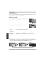
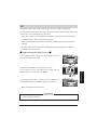
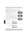
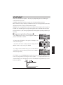
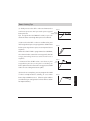
1
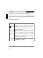
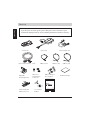
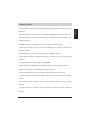
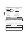
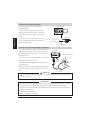
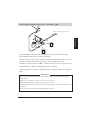
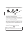
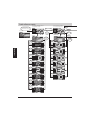
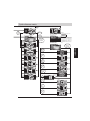
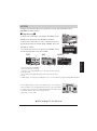
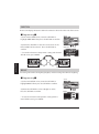
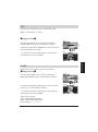
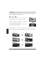
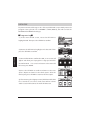
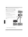
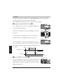
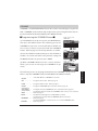
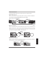
EXTREME POWER ENHANCEMENT PRODUCTS BY GREDDY
instruction manual
取扱説明書
Please read this manual thoroughly before installation and operation.
Please read.
Thank you very much for your recent purchase: GReddy Profec. Please read this manual
thoroughly before installation and operation. We hope this instruction manual will be helpful
to you whether you are a novice or a technician. This product is intended for off-road use.
Please keep this manual for future reference.
Disclaimer
Please read
To the best of our knowledge, the information contained herein is accurate.
However, neither TRUST CO., LTD or any of its subsidiaries assumes any liability
whatsoever for the accuracy or completeness of the information contained herein. All
materials may present unknown hazards and should be used with caution. In particular,
improper use of our products and their inappropriate combination with other products and
substances may produce harmful results which cannot be anticipated. Final determination
of the suitability of any material is the sole responsibility of the user. Although certain
hazards are described herein, we cannot guarantee that these are the only hazards that
may exist. All service performed on internal parts and equipment should be provided by
qualified technicians.
Table of Contents
Contents
Contents
Installation
Installation
Operations
Operations
Configurations
Configurations
Troubleshooting
Troubleshooting
Boost settings
Boost settings
Please
Read
・
・
・
・
・
・
・
・
・
・
・
・
・
・
・
・
・・
・
・
・
・
・
・
・
・
・
・
・
・
・
・
・
・
・
・
・
・
・
・
・
・
・P1
Introduction ・
・
・
・
・
・
・
・
・
・
・
・
・
・・
・
・
・
・
・
・
・
・
・
・
・
・
・
・
・
・
・
・
・
・
・
・
・
・P2
Table of Contents ・
Please
Read
・
・
・
・
・
・
・
・
・
・
・
・
・
・
・
・
・
・・
・
・
・
・
・
・
・
・
・
・
・
・
・
・
・
・
・
・
・
・
・
・
・
・
・P3∼6
Disclaimers ・
・
・
・
・
・
・
・
・
・
・
・
・
・
・
・
・
・
・
・
・
・・
・
・
・
・
・
・
・
・
・
・
・
・
・
・
・
・
・
・
・
・
・
・
・
・P7
Parts List ・
・
・
・
・
・
・
・
・
・
・
・
・
・・
・
・
・
・
・
・
・
・
・
・
・
・
・
・
・
・
・
・
・
・
・
・
・
・
・P8
Product Features ・
Please
Read
・
・
・
・
・
・
・
・
・
・
・
・
・
・
・
・
・
・
・P9
Product description / Before installation ・
・
・
・
・
・
・
・
・
・
・
・
・
・
・
・
・
・
・
・
・
・
・P10
Installation overview (Actuator type) ・
Power unit wiring instructions / Pressure sensor hose routing instructions ・
・P11
・
・
・
・
・
・
・
・
・
・
・
・
・
・
・
・
・
・
・
・
・
・
・
・P12,13
Installing the solenoid valve unit ・・
・
・
・
・
・
・
・
・
・
・
・P14
Installing the solenoid valve unit (Actuator type) ・
・
・
・
・
・
・P15
Installing the solenoid valve (External wastegate type) ・
・
・
・
・
・
・
・・
・
・
・
・
・
・
・
・
・
・
・
・
・
・
・
・
・
・
・
・
・
・
・
・
・P16
Control unit installation ・
Please
Read
・
・
・
・
・
・
・
・
・
・
・
・
・
・
・・
・
・
・
・
・
・
・
・
・
・
・
・
・
・
・
・
・
・
・
・
・
・
・
・
・P17
Basic operation ・
・
・
・
・
・
・
・・
・
・
・
・
・
・
・
・
・
・
・
・
・
・
・
・
・
・
・
・
・
・
・
・
・P17,18
Opearating instructions ・
・
・
・
・
・
・
・
・
・・
・
・
・
・
・
・
・
・
・
・
・
・
・
・
・
・
・
・
・
・
・
・
・
・P19,20
Quick reference matrix ・
・
・
・
・
・
・
・
・
・
・
・
・
・・
・
・
・
・
・
・
・
・
・
・
・
・
・
・
・
・
・
・
・
・
・
・
・
・
・P21
SET UP overview ・
・
・
・
・
・
・
・
・
・
・
・
・
・
・
・
・
・
・
・
・
・・
・
・
・
・
・
・
・
・
・
・
・
・
・
・
・
・
・
・
・
・
・
・
・
・P22
PATTERN ・
・
・
・
・
・
・
・・
・
・
・
・
・
・
・
・
・
・
・
・
・
・
・
・
・
・
・
・
・
・
・
・
・P23
DIRECTION / BRIGHT ・
・
・
・
・
・
・
・
・
・
・
・
・
・
・・
・
・
・
・
・
・
・
・
・
・
・
・
・
・
・
・
・
・
・
・
・
・
・
・
・P24
UNIT / ALARM ・
・
・
・
・
・
・
・
・
・
・
・
・
・
・
・
・
・・
・
・
・
・
・
・
・
・
・
・
・
・
・
・
・
・
・
・
・
・
・
・
・
・P25
LAST BOOST ・
・
・
・
・
・
・
・
・
・
・
・
・
・
・
・
・
・・
・
・
・
・
・
・
・
・
・
・
・
・
・
・
・
・
・
・
・
・
・
・
・
・P26
START TYPE ・
・
・
・
・
・
・
・
・
・
・
・
・
・
・
・
・
・
・
・・
・
・
・
・
・
・
・
・
・
・
・
・
・
・
・
・
・
・
・
・
・
・
・
・P27,28
DATA LOCK ・
・
・
・
・
・
・
・・
・
・
・
・
・
・
・
・
・
・
・
・
・
・
・
・
・
・
・
・
・
・
・
・
・P29
Programming overview ・
・
・
・
・
・
・
・
・
・
・
・
・
・
・
・
・
・
・
・
・
・
・
・
・
・・
・
・
・
・
・
・
・
・
・
・
・
・
・
・
・
・
・
・
・
・
・
・
・
・
・P30
SET ・
・
・
・
・
・
・
・
・
・
・
・
・
・
・
・
・
・
・
・
・
・
・
・
・・
・
・
・
・
・
・
・
・
・
・
・
・
・
・
・
・
・
・
・
・
・
・
・
・
・P31
GAIN ・
・
・
・
・
・
・
・
・
・
・
・
・
・
・
・・
・
・
・
・
・
・
・
・
・
・
・
・
・
・
・
・
・
・
・
・
・
・
・
・
・P32
START BOOST ・
・
・
・
・
・
・
・
・
・
・
・
・
・
・
・
・
・
・
・
・
・
・
・
・・
・
・
・
・
・
・
・
・
・
・
・
・
・
・
・
・
・
・
・
・
・
・
・
・
・P33
PEAK ・
・
・
・
・
・
・
・
・
・
・
・
・
・
・
・
・
・
・
・
・・
・
・
・
・
・
・
・
・
・
・
・
・
・
・
・
・
・
・
・
・
・
・
・
・P34
WARNING ・
・
・
・
・
・
・
・
・
・
・
・
・
・
・
・
・
・
・
・
・
・
・・
・
・
・
・
・
・
・
・
・
・
・
・
・
・
・
・
・
・
・
・
・
・
・
・P35
LIMITER ・
・
・
・
・
・
・
・
・
・
・
・
・
・
・
・
・
・
・
・・
・
・
・
・
・
・
・
・
・
・
・
・
・
・
・
・
・
・
・
・
・
・
・
・P36
SCRAMBLE ・
・
・
・
・
・
・
・
・
・
・
・
・
・
・・
・
・
・
・
・
・
・
・
・
・
・
・
・
・
・
・
・
・
・
・
・
・
・
・
・P37
SWITCH MODE ・
・
・
・
・
・
・
・
・
・
・
・・
・
・
・
・
・
・
・
・
・
・
・
・
・
・
・
・
・
・
・
・
・
・
・
・P38
Short cut commands ・
・
・・
・
・
・
・
・
・
・
・
・
・
・
・
・
・
・
・
・
・
・
・
・
・
・
・
・P39
Troubleshooting / Test mode ・
・
・
・
・
・
・
・
・
・
・
・
・
・・
・
・
・
・
・
・
・
・
・
・
・
・
・
・
・
・
・
・
・
・
・
・
・
・
・P40
Boost setting tips ・
・
・
・
・
・
・
・
・
・
・
・
・
・
・
・
・P41
Factory default settings / Trouble shooting ・
・
・
・
・
・
・
・
・
・
・
・
・
・
・
・
・
・
・
・
・
・
・
・・
・
・
・
・
・
・
・
・
・
・
・
・
・
・
・
・
・
・
・
・
・
・
・
・P42
Service ・
Safety advice
Please read carefully
These instructions are intended for qualified personnel only.
Contents
To reduce the risk of electrical shock, do not perform any servicing
other than that contained in the Installation and Troubleshooting
Instructions unless you are qualified to do so. Refer all servicing to
qualified service personnel.
This symbol indicates that hazards are present
within the equipment. These hazards may be of
Warning
sufficient to cause serious bodily injury if
installed improperly. The symbol may also
appear on schematics.
The exclamation point, within an equilateral
triangle, is intended to alert the user to the
Caution
presence of important installation, servicing, and
operating instructions in the documents
accompanying the equipment.
Important
Precautions before installation. The word may
also appear on schematics.
Please read carefully
Safety advice
Warning
specialist who is very familiar with the automobile s mechanical, electrical
and fuel management systems. If installed by an untrained person, it may
cause damage to the unit as well as the vehicle.
Do not work on a vehicle that has recently been shut off. The exhaust system
may be extremely hot and could cause burn injury.
Professional installation is recommended. There is a risk of injury if performed
by an untrained person.
Be sure to inspect and examine all mounting surfaces and locations.
Improperly mounted controllers can fall while driving the vehicle. This could
cause serious injury or damage.
Do not attempt to operate the product while driving. Doing so may cause an
accident.
Before moving the vehicle, make sure that your work area is clear of tools and
is safe to drive through. Make sure that there are no tools or objects in the car
that will keep you from operating the vehicle in a safe manner.
Make sure that the installation of fuel sensors is done somewhere that is well
ventilated. Fuel is flammable and may cause serious injury if not handled
properly.
When using soldering irons and nippers, please read their operating manuals
prior to use. Improper use of this equipment may lead to injury or illness.
Contents
Installation and tuning of this product should only be performed by a trained
Safety advice
Please read carefully
Contents
Caution
Increasing boost levels is a practice that is not advised by original
equipment automobile manufacturers. While doing so will lead to more
power output, it can very well lead to engine damage or complete engine
failure if done improperly. The addition of more power to any vehicle
requires due caution while the driver becomes acclimated. TRUST Co.,LTD.
and its subsidiaries are not liable for any damage or injury that may arise
from the use of the device.
Depending on the vehicle, some applications will trigger a fuel cut when
raising the boost pressure, in these circumstances, you need an e-manage
or similar unit to the control fuel cut.
Incorrect wiring could lead to damage to your cars electrical system.
Be sure to verify that all the sensors are installed using sealing tape. After
installation of sensors, be sure to check for leaks such as oil, coolant and/or
fuel.
Do not disassemble the product. Doing so will lead to the forfeit of
warranty coverage.
When making wire connections, be sure to remove the key from the
ignition, and disconnect the negative terminal of the battery.
Do not install in electrically noisy environments such as ignition signal
areas. This could lead to sensor glitch or malfunction.
Safety advice
Please read carefully
The product is for racing vehicles only.
This product is for use ONLY on vehicles with a 12V electrical system.
Please make sure to read the safety precautions described in each category.
TRUST CO., LTD
TEL : 0479 (77) 3000
3155-5 Odai Shibayama-machi Sanbu-gun Chiba, Japan 289-1605
Contents
Important
Parts List
Contents
If you find you are missing parts, please bring this to the attention of your
Authorized GReddy Dealer or contact GReddy Performance Products directly.
Control unit
Sensor unit
Solenoid valve harness(1.5m)
Adjustable
mounting bracket
4Φhose (1m)
M6 bolt x 1
Anti-vibration
isolator x 2
Solenoid valve unit
4Φhose (1m)
6Φhose fitting x 2
Hose clamp x 2
TRUST SUPER TUNING SYSTEMS AIMED AT REAL COMPETITORS
Instruction manual
Valve unit bracket
M4 bolt & nut x 2
Y connector
Air filter
取扱説明林
ご使用の前にこの取扱説明書をよくお読みになり、十分理解された上で
正しくお使いください。
Instruction manual
6Φhose (1m)
Double-sided tape
Product Features
- Utilizes OLED (organic light-emitting diode) display for improved viewing angles &
- Monitor boost pressure in real time. 3 selectable display patterns for boost pressure
- By separating the Control unit from the Power unit, the Profec greatly improves the
installation process.
- Additional flush mounting options due to the thin 11mm thick design.
- 180-degree rotatable display screen for flexibility in the layout of controls and
installation options.
- High-performance pressure sensor supports up to 300kPa (43.5psi).
- High capacity compact solenoid valve and the new CPU increase the speed of the
controller.
- Configurable boost modes: LO, HI, and SCRAMBLE.
- Adjustable SET%, START BOOST and GAIN% settings ensure stable boost curves.
- Warning function when exceeding the preset boost value.
- Limiter control function: to decrease boost when above the alarm setting.
- Last boost function: to confirm the highest boost value set in the most recent boost
session.
- Peak hold function: capable of recalling the maximum boost pressure value
recorded.
- Data lock function: to protect the programmed settings and avoid accidental
changes.
Contents
brightness.
Product Description
1
5
2
Installation
3
4
8
7
Power unit
Control unit
5. Mounting flange
6. Main harness
1. Display
2. SELECT switch
3. MODE switch
4. SET DIAL
7. Boost Pressure Sensor
8. Valve unit harness connector
Please read carefully
Before Installation
Tools & Instruments
6
・Multi-meter (Over 15V measurement capability)
・10mm wrench
・Electrical tape
・Wire cutters
・Wire cutters
・Splice connectors
・+Phillips and -Slotted Screwdrivers
・Soldering iron
・Soldering iron
・Pliers
・Crimping tool
・Cable ties
・Make sure that engine is cool when you begin the installation.
・Make sure that hoses are long enough to reach valve unit, before you mount it.
・Before the installation, find the locations of wastegate, boost control solenoid
valve, fuel pressure regulator.
For the technician
Please return this manual to the customer when installation and mounting are
completed.
For the user
When the person other than the owner uses a vehicle, please tell him/her that
Profec is installed and pass this instruction manual to the person.
Installation Overview (Actuator type)
The Profec Sensor unit is waterproof and can be safely mounted in the engine bay.
Only one main harness line is required to be routed through the firewall to the
driver s compartment. The control unit is only water resistant. Therefore, do not
install it in a location, where it could get wet or be in excessive heat.
avoiding direct sunlight.
Control unit
Installation
IInstall in a cool place
+12V ACC (Accessory) Power
Chassis Ground
Driver s compartment
Engine Bay
Sensor unit
4Φhose
It is possible to connect the
Filter
Solenoid valve unit directly to the
Sensor unit, without using the
solenoid valve harness.
Actuator
Engine
Throttle
Turbine
Fuel Pressure Regulator
Intercooler
Air cleaner
Solenoid Valve Unit
Power unit wiring instructions
(1) Find the (12V) ACC (Accessory) wire by
Controller unit
using multi-meter.
(2) Disconnect the ground wire from the
battery, and solder (or use splice connector)
on the ACC wire to the red wire on the power
harness.
Installation
(3) Solder (or use an electrical connector) to
connect the black ground wire from Profec
Sensor unit
+12V ACC (Accessory) Power
with a chassis ground.
Chassis Ground
Power harness
Pressure sensor hose routing instructions
(1) Cut the vacuum hose between intake manifold
and fuel pressure regulator or between throttle and
Sensor unit
intake manifold, and connect the Y joint connector
Fuel pressure regulator
in between them.
(2) Then connect the provided 4Φhose to third
opening on the Y joint connector.
(3) Adjust the length of 4Φhose and install air filter
Air filter
on the other end.
(4) Install another piece of the 4Φhose from air filter
to the boost pressure sensor nipple on the Sensor
unit
Warning
Y connector
Please make sure that the 4mm hoses are secured with cable ties to prevent them from
disconnecting.
Important
・For Toyota s JZ engines, Mitsubishi s 4G63 engines and engines with fuel pressure controlling
solenoids, make sure to tap the pressure in between intake manifold and fuel pressure
control solenoid. (do not install on the line between the fuel pressure control solenoid and
fuel pressure regulator.)
・Make sure to install air filter.
・Replace air filter if it is very dirty.
Installing the solenoid valve unit ‒ (Actuator Type)
Actuator
Turbo compressor pressure source
2
(1) Install a 6Φhose fitting to both the [1] & [2] ports on the solenoid valve unit.
(2) Assemble the valve unit as shown in the picture.
(3) Disconnect the factory hose between Actuator and turbo compressor, and
connect the Turbo compressor to the [1] port of the solenoid valve unit.
(4) Next, install the provided 6Φhose from the Actuator to the [2] port of the
solenoid valve unit. Adjust the length of the hose as needed.
* Refer to page 14 for vehicles equipped with a factory boost pressure solenoid
valve.
Important
・Don't install the product in any place where it will be subjected to direct sunlight or high
temperatures.
・Make sure to use cable ties on the hoses for secure connections.
・When installing hoses, be careful not to kink or twist the hoses.
・Audible clicking noises from valve unit may be heard from the solenoid. It is normal and is not
a problem.
・Mount the valve unit with the provided anti-vibration isolators.
Installation
1
Installing the solenoid valve unit ‒ (Twin Actuator Type)
■Twin Turbo Vehicles■
Actuators
Turbo compressor
Installation
pressure sources
1
2
For twin turbo applications, two Y connectors will be required. However, the
installation procedure is the same as Page 12. Place a Y connector to connect the
[1] port of the solenoid valve to the two ports for Turbine compressor as shown in
the diagram above. The same applies for the [2] port of the solenoid valve, use a Y
connector to connect the two wastegate actuators.
Installing the solenoid valve unit ‒ (Actuator Type with a Factory
Boost Control Solenoid Valve)
For vehicles with factory boost pressure control solenoid valves, please follow
the directions below.
Before
Method 2
Engine
Engine
Turbine
Throttle
Turbine
Throttle
Factory boost pressure
control solenoid valves
Factory boost pressure
control solenoid valves
Air filter
Air filter
Intercooler
Intercooler
After
Throttle
Throttle
Solenoid valve
unit
Turbine
Factory boost pressure
control solenoid valves
Intercooler
Solenoid valve
unit
Turbine
Factory boost pressure
control solenoid valves
Air filter
Intercooler
Air filter
Place rubber caps on the solenoid valves where hoses were previously
connected. Secured caps with cable ties to prevent them from
disconnecting. (rubber caps are not provided in this kit)
Installation
Method 1
Installing the solenoid valve unit ‒ (External Wastegate Type)
Turbo compressor
pressure source
3
Installation
Wastegate Dump
(secondary) Port
Turbo compressor
pressure source
2
(1) Install a 6Φhose fitting to both the [2] & [3] ports on the solenoid valve unit.
(2) As shown above, assemble valve unit with provided bracket and anti-vibration
isolators and install in the engine bay near the wastegate.
(3) Install the correct 6Φ hose fitting (sold separately) to wastegate dump (secondary)
port (usually located on the top of the wastegate.)
(4) Connect a 6Φhose between newly installed 6Φhose fitting and the [2] port on the
solenoid valve. Cut and adjust the hose length as needed.
(5) Connect another piece of 6Φhose from the [3] port on the solenoid valve unit to a
stable boost pressure source from the intake manifold or the turbocharger s
compressor charge pressure pipe. (*Be sure to have a boost pressure source
connecting the main lower wastegate port to a stable boost pressure source, as well
‒ see diagram).
* For twin turbo applications with twin external wastegates, place a Y connector
(sold separately) to split the connection from the [2] port of the solenoid valve unit
and connect to two upper dump (secondary) ports of the wastegates.
Important
・Don't install the product in any place where it will be subjected to direct sunlight or high temperatures.
・Make sure use cable ties on the hoses for secure connections.
・When installing hoses, be careful not to kink or twist the hoses.
・Audible clicking noises from valve unit may be heard from the solenoid. It is normal and is not a problem.
・Mount the valve unit with the provided anti-vibration isolators.
Control Unit Installation
Once the electrical wiring is complete, find a suitable mounting location for the
Control unit. You may use the provided Adjustable bracket or flush mount the unit
with the provided double sided tape.
■How to install■
Installation
(1) Adjust the angle of mounting
bracket to find the best position
of controller. Tighten left & right
bracket bolts with hex wrench.
(2) Place controller in the
adjustable bracket. Attach the
Route the harness between
back of the controller into the
the bracket uprights
relief in the bracket until it locks
as shown.
into place. The controller can be
inverted, so that the dial on right
side or left side.
Warning
For safety, avoid mounting the unit near air-bags.
Caution
When using the double-sided tape, clean mounting surfaces from oil and
debris with a mild detergent for best results.
Important
Be sure to mount the unit in a safe location that will not effect safe driving.
Avoid direct sunlight and humidity.
Please read carefully
Inspection after Installation
(1) Check for good connections between the Power harness, Valve unit and Control
unit.
(2) Reinstall factory parts as needed.
(3) Double check all harnesses and hoses for proper installation.
(4) Reattach the negative terminal to the battery.
Operations
(5) Start the engine and confirm the Profec controls and display are functional.
(6) While the engine is idling, confirm the Profec recognizes vacuum pressure.
(7) Double check hoses for air leaks.
Important
・Shut down the vehicle, if any problems occur.
・Refer to the Profec Test mode, to troubleshoot.
・Refer to page 18 and 39 for the Test mode and Troubleshooting the Profec.
Basic operation
1. SELECT switch
1
- Push: SELECT to toggle between BOOST HI - BOOST LO.
- Push & Hold-down: SELECT to Power ON or OFF.
2. MODE switch
- Push : MODE to toggle between the Real-time (boost gauge) display and a
Control unit
2
3
set-up screen. While in the SETUP mode screen, pushing MODE will cancel
the changes made.
- Push & Hold-down: MODE to reset the recorded peak value.
3. SET DIAL
- Turn : SET DIAL to change the settings and to scroll through menus. In
Real-time (boost gauge) mode, it activates a shortcut to changing the SET%
value.
- Push : SET DIAL to confirm program settings. In Real-time (boost gauge)
mode, switch from LO or HI mode to SCRAMBLE mode.
Important
・Please use care when operating the SET DIAL. Be careful not to use excessive
force on the controls.
Operating Instructions
Profec can switch from Real-time (boost gauge) display to other set-up screens.
Please follow basic operations below, to switch between different display patterns.
Refer to the page 19 and 20 for a quick reference chart.
■Power ON/OFF■
In Real-time (boost gauge) display for
Real-time display HI/LO
BOOST LO or HI mode, hold down
Hold down
SELECT
Real-time display OFF
SELECT for 2 seconds to power Off the
boost controller. To power On the boost
controller, follow the same procedure.
■Basic setting■
Real-time display OFF
SET UP
MODE
display for OFF mode, press MODE to go
to the unit s main SET UP screen.
Refer to page 21.
■Boost setting screen■
Real-time display HI/LO
Boost setting list HI/LO
MODE
From the Real-time (boost gauge)
display for LO or HI mode, press MODE
to go to the BOOST mode s SET UP
screen. Refer to page 29.
■Switching HI/LO■
Real-time display LO
From the Real-time (boost gauge)
Real-time display HI
SELECT
display for LO or HI mode, press SELECT
to toggle between HI and LO modes.
Important
・It is important to note that when the boost controller is in the OFF mode, boost is only controlled by
the wastegate spring tension. It is common for vehicles that had factory boost control solenoids
removed, to have lower then factory base boost levels.
・Depending on the vehicle s wastegate or actuator spring tension, base boost levels many very.
・A boost controller cannot lower the boost pressure below the wastegate and actuator s base
boost level.
・Turning OFF the Profec boost controller will not turn off the unit s backlighting or Real-time
(boost gauge) display.
Operations
From the Real-time (boost gauge)
Quick reference matrix
OFF mode s Real-time (boost
gauge) display screen
Press SET DIAL, SELECT
and MODE at the same time.
BOOST LO mode s Real-time
(boost gauge) display screen
Hold down SELECT
Test mode
MODE
SET DIAL
or
MODE
SELECT
Boost setting
screen LO
SET UP
Select items
and press
SET DIAL
SET DIAL
or
MODE
Operations
SET DIAL
or
MODE
SET DIAL
or
MODE
SET DIAL
or
MODE
SET DIAL
or
MODE
SET DIAL
or
MODE
SET DIAL
or
MODE
PATTERN
DIRECTION
BRIGHT
UNIT
ALARM
LAST BOOST
START TYPE
DATA
LOCK
DATA LOCK
or
MODE
to cancel
SET
MODE
Turn
SET DIAL
SELECT
Select items
and press
SET DIAL
SET DIAL
or
MODE
SET DIAL
or
MODE
SET DIAL
or
MODE
SET DIAL
or
MODE
SET DIAL
or
MODE
SET DIAL
or
MODE
SET
GAIN
START BOOST
PEAK
WARNING
LIMITER
Quick reference matrix
BOOST HI mode s Real-time (boost gauge) display screen
SET DIAL
or
MODE
MODE
Boost setting screen HI
SET DIAL
or
MODE
SET DIAL
or
MODE
SET DIAL
or
MODE
SET DIAL
or
MODE
SET DIAL
or
MODE
SCRAMBLE mode
Turn
SET DIAL
SELECT
PEAK
WARNING
SELECT
The factory default setting for
the SCRAMBLE SELECT mode
is set to OFF. To display the
program set up screen for
SCRAMBLE mode, change the
SCRAMBLE SELECT setting to
ON.
Select items
and press
SET DIAL
Boost setting screen
SCRAMBLE ON
GAIN
START BOOST
Back to
Boost setting screen LO
Boost setting screen
SCRAMBLE OFF
Select items
and press
SET DIAL
SET DIAL
or
MODE
SELECT
SET DIAL
or
MODE
SET
SET DIAL
or
MODE
GAIN
SET DIAL
or
MODE
START BOOST
When MANUAL
is selected
or
MODE
LIMITER
TIME
SET
SWITCH MODE
When PRESET
is selected.
SET DIAL
or
MODE
PEAK
SET DIAL
or
MODE
WARNING
SET DIAL
or
MODE
LIMITER
Operations
SET DIAL
or
MODE
SET
SET
SET UP
Overview
You can configure settings for the displays, units, and sounds.
OFF mode s Real-time
(boostgauge) display
screen
■Programming■
(1) When in the Real-time (boost gauge)
screen for the OFF mode, press MODE
to display the unit s main SET UP
screen.
SET UP
MODE
(2) When in the main SET UP screen,
turn the SET DIAL to select an item to
change.
Configurations
PATTERN・・・ Configures the Real-time (boost gauge) display s pattern type. - Refer to page 22.
DIRECTION・・・ Configures the display s orientation. Refer to page 23
BRIGHT・・・ Configures the brightness of the display and the switch s backlighting.
- Refer to page 23
UNIT・・・ Configures either metric or standard pressure units. - Refer to page 24.
ALARM・・・ Configures the alarm sound patterns for the warning and limiter functions.
- Refer to page 24
LAST・・・ Configures if the LAST BOOST is activated. - Refer to page 25
(Last Boost)
ST.TYPE・・・ Configures the START BOOST program type.
(Start Type)
- Refer to page 26
- Refer to page 26
LOCK・・・Configures the DATA LOCK and password. - Refer to page 27 ‒ 28
(Data Lock)
PATTERN
Configure the Real-time (boost gauge) display settings type (for BOOST LO, HI,
SCRAMBLE, and OFF modes).
■Programming■
SET UP
(1) Rotate the SET DIAL to highlight PATTERN in the
SETUP screen. Then press the SET DIAL to confirm.
(2) Rotate the SET DIAL to select a Real-time (boost
gauge) display pattern. (DIGIT / BAR / GRAPH) Press the
SET DIAL to confirm.
SET
PATTERN
* To cancel and return to the previous PATTERN setting
and the main SET UP screen, press MODE
DIGIT
1
2
1.
2.
3.
4.
5.
6.
7.
2
6
1
4
5
3
GRAPH
1
7
4
3
2
4
Boost Mode (LO, HI, or SCRAMBLE)
Numeric Real-time boost reading.
Peak value - the reading will blink for 3 seconds when the value is updated
Units (kPa or PSI)
Boost reading - The reading will display negative and positive pressures.
(0PSI)
GRAPH display ‒ The map tracing will display the past 10 seconds (above the programmed Graph Minimum Value)
Once the GRAPH display is confirmed, the GRAPH SET UP screen will appear.
When GRAPH is selected.
Turn the SET DIAL to select the Graph Minimum Value. Then press the SET DIAL
to confirm. (any boost pressure over this Graph Minimum Valve will be charted
on the GRAPH display, readings under will not be shown.)
Setting ranges: 0 3.00 x 100kPa
★Refer to page 38 for shortcuts.
Configurations
3
BAR
DIRECTION
Reverse the display direction to allow the controls to be on the other side of the screen.
■Programming■
SET UP
(1) In the main SETUP screen, rotate the SET DIAL to
highlight DIRECTION. Then press the SET DIAL to confirm.
(2) Rotate the SET DIAL to select the screen to be on the
LEFT or RIGHT of the controls. Press the SET DIAL to
SET
DIRECTION
confirm.
* To cancel and return to the previous setting and the main
SET UP screen, press MODE.
Configurations
LEFT
RIGHT
BRIGHT
Increasing value makes the lighting brighter, and decreasing value dims the lighting.
■Programming■
(1) In the main SETUP screen, rotate the SET DIAL to
SET UP
highlight BRIGHT. Then press the SET DIAL to confirm.
(2) Rotate the SET DIAL to select a brightness value.
Press the SET DIAL to confirm.
* To cancel and return to the previous setting and the
main SET UP screen, press MODE.
SET
BRIGHT
UNIT
Configure the display boost units in either kPA or PSI.
100kPa=1.01972kg/cm =14.5PSI
2
■Programming■
(1) In the main SETUP screen, rotate the SET DIAL to
highlight UNIT. Then press the SET DIAL to confirm.
(2) Rotate the SET DIAL to highlight and select kPa or PSI.
Press the SET DIAL to confirm.
* To cancel and return to the previous setting and the
main SET UP screen, press MODE.
SET UP
SET
UNIT
Configurations
ALARM
Configure the alarm sounds of warning and limiter.
■Programming■
(1) In the main SETUP screen, rotate the SET DIAL to
highlight ALARM. Then press the SET DIAL to confirm.
SET UP
SET
(2) Rotate the SET DIAL to highlight and select an Alarm
pattern. Press the SET DIAL to confirm.
* To cancel and return to the previous setting and the
main SET UP screen, press MODE.
Alarm off : No Sound
Alarm 1: Beep Beep, Beep Beep
Alarm 2: Beep, Beep, Beep, Beep
Alarm 3: Beep---------------------
ALARM
LAST BOOST
Displays the highest boost reading from the last boost session, when the throttle is
released. Configure the feature ON or OFF.
■Programming■
(1) In the main SET UP screen, rotate the SET DIAL to
SET UP
highlight LAST. Then press the SET DIAL to confirm.
(2) Rotate the SET DIAL to highlight and select ON or
OFF. Press the SET DIAL to confirm.
SET
LAST BOOST
* To cancel and return to the previous setting and the
main SET UP screen, press MODE.
When LAST BOOST is set to ON, every time one drives (gets positive to negative
Configurations
pressures), the highest peak value will blink for 3 seconds on the real time display.
DIGIT driving
Off throttle
BAR driving
Off throttle
GRAPH driving
Off throttle
START TYPE
Determines how the boost controller will function until the START BOOST value.
■Programming■
(1) In the main SET UP screen, rotate the SET DIAL to
SET UP
highlight ST.TYPE. Then press the SET DIAL to confirm.
SET
(2) Rotate the SET DIAL to highlight and select CONTROL or
START TYPE
NORMAL. Press the SET DIAL to confirm.
* To cancel and return to the previous setting and the
main SET UP screen, press MODE.
CONTROL : START (BOOST) attempts to control the wastegate with the solenoid valve
NORMAL: START (BOOST) only activates the boost control solenoid from the
programmed START (BOOST) value on.
Example:
If the START BOOST value is programmed at 0.7x100kPa, CONTROL will allow for
quicker boost response.
Boost
0.7×100kPa
CONTROL(Maximum control)
NORMAL(limited control)
Time
Configurations
for the entire boost range.
DATA LOCK
To prevent unwanted changes or loss of data, DATA LOCK can password protect the
program setting for LO / HI / SCRAMBLE / START (BOOST), but will not lock the
PATTERN and ALARM from changes.
■Programming■
(1) In the main SET UP screen, rotate the SET DIAL to
SET UP
highlight LOCK. Then press the SET DIAL to confirm.
SET
DATA LOCK
(2) Rotate the SET DIAL to highlight and select ON. Then
press the SET DIAL to confirm.
SET
Configurations
(3) Once DATA LOCK is confirmed to ON, a new screen will
Entry of the 3-digit password
appear and allow you to program a 3 digit password for
the DATA LOCK. * To cancel and return to the main SET
UP screen, press MODE.
(4) Press the SET DIAL to confirm and move to the next
SET
Entry of the 3-digit password
square. Repeat and move to the third square. After the
third square, press SET DIAL to return to the first square.
(5) After entering the 3 digit password, hold down SET DIAL
for 3 seconds to save. Once saved, there will be a chime
and the screen will return to the main SET UP screen.
Hold down
SET DIAL
Confirmation screen
DATA LOCK
When the DATA LOCK is ON, the lock icon will appear on the
DATA LOCK
upper right corner of the screen. With DATA LOCK ON, the
preset values can be displayed but cannot be changed.
Important
DATA LOCK ICON
Please make note of your password. It cannot be recalled.
■Programming■
(1) In the main SET UP screen, rotate the SET DIAL to
SET UP
highlight LOCK. Then press the SET DIAL to confirm.
SET
the SET DIAL to confirm.
SET
(3) Input password on the DATA LOCK display using the SET
Entry of the 3-digit password
DIAL.
SET UP screen
(4) After entering the password, hold down SET DIAL for 3
seconds to confirm. Once the password is accepted, there
will be chime and the screen will return to the main SET UP
screen. To restore password, refer to page 39.
Hold down
SET DIAL
Configurations
(2) Rotate the SET DIAL to highlight and select OFF. Press
DATA LOCK screen
Boost settings
Programming Overview
Display or program the BOOST LO / BOOST HI / BOOST SCRAMBLE mode settings.
Refer to page 36 37 regarding SCRAMBLE mode.
■Programming■
(1) In Real-time (boost gauge) display for BOOST LO or HI
Real-time display
mode, press MODE to display that mode s set up screen.
MODE
(2) Turn the SET DIAL to highlight the item you wish to
Mode s set up screen LO
change. Press the SET DIAL to confirm.
・SET ・・・・・・・ SET --- Program a SET % value. Refer to p30.
・GAIN ・・・・・・ GAIN --- Program a GAIN % value. Refer to p31.
・START
・・・・・ START --- Program a START BOOST pressure value. Refer to p32.
(START BOOST)
・PEAK ・・・・・・ PEAK --- Recall & Reset the recorded PEAK boost pressure value. Refer to p33.
Boost settings
・WARNING ・・・・ WARNING --- Program a WARNING boost pressure value. Refer to p34.
・LIMITER ・・・・・ LIMITER --- Program a LIMITER % value. Refer to p35.
■How to change to another BOOST LO/HI/SCRAMBLE mode s set up screen■
In a BOOST mode s set up screen, press SELECT to toggle to the next BOOST mode
set up screen. BOOST LO / BOOST HI / BOOST SCRAMBLE mode set up.
Mode s set up screen LO
Mode s set up screen HI
SELECT
SELECT
Mode s set up screen
SCRAMBLE
SELECT
SET
Changes the boost pressure by controlling the boost control solenoid valve.
This SET value in percentage (%) adjusts the boost control solenoid valve duty cycle,
it does not set an actual boost pressure value.
・As the SET % value is increased between 0-100%, it increases the boost level over
the turbocharger s base wastegate boost level.
・100% value will increase the boost level of the turbocharger systems maximum
capacity.
・0% value will be the base boost level turbocharger system (boost can not be set
below the base boost level).
■Programming the Boost Pressure■
(1) In a BOOST mode set up screen, highlight SET and
Mode s set up screen
press the SET DIAL to confirm.
SET
(2) Rotate the SET DIAL to change a SET % value.
SET
To cancel and return to the previous setting and the
SET
(3) To program the SET % value, press the SET DIAL to
Mode s set up screen
confirm and return to the BOOST mode set up screen.
* Refer to page 38 for SET shortcuts.
Important
・There may be vehicles or turbocharger set-ups which are unable to reach
your target boost pressure.
Boost settings
BOOST mode set-up screen, press MODE.
GAIN
Controls the boost curve tendency after the START pressure value. (stability and
consistency at higher RPMs)
・Program a boost level with the SET and START, before adjusting the GAIN.
・If the START pressure value is set to 0x100kPa or 0PSI, GAIN will not function.
■Programming the Boost Stability■
Mode s set up screen
(1) In a BOOST mode set up screen, highlight GAIN and
press the SET DIAL to confirm.
(2) Rotate the SET DIAL to change a GAIN % value.
* To cancel and return to the previous setting and the
SET
GAIN
BOOST mode set-up screen, press MODE.
(3) To program the GAIN % value, press the SET DIAL to
confirm and return to the BOOST mode set up screen.
SET
To improve boost from dropping at higher RPM (boost fall
off), adjust the GAIN to a positive value. There may be
Mode s set up screen
vehicles or turbocharger configurations which will not
allow for improvements.
Boost settings
Boost
Adjust GAIN value to +
Time
Once the SET and START pressure values are adjusted to obtain the desired boost pressure, the GAIN can also be
used to drop boost pressure at higher RPMs by setting a negative value for the GAIN.
Boost
Adjust GAIN value to ‒
Time
If the GAIN value is programmed too high, it may cause unstable boost, with a
fluctuating boost curve (boost creep).
Affects the initial boost response. This may vary depending on the ST.TYPE style
selected. Refer to page 26.
CONTROL: Maximizes the boost response to the targeted boost pressure.
Boost will rise faster by selecting a START value closer to the targeted boost pressure.
(however too hi of a setting can initiate boost spike)
NORMAL: In this configuration the boost controller will not improve boost response,
but will start controlling the wastegate through the boost solenoid from this boost
pressure value on. (this setting maybe ideal for already quick spooling turbocharger
systems)
■Programming the Boost Response■
Mode s set up screen
(1) In a BOOST mode set up screen, highlight START and
press the SET DIAL to confirm.
(2) Rotate the SET DIAL to change the START pressure
value activation point.
SET
START BOOST
* To cancel and return to the previous setting and the
BOOST mode set-up screen, press MODE.
confirm (this action will bring you back to the BOOST
SET
Mode s set up screen
mode set-up screen).
If ST. TYPE is set to CONTROL, Boost Spike may occur when the START pressure
value is programmed too high. Boost Spike --- is a phenomenon that
unintentionally causes the boost pressure to overshoot the targeted boost pressure
before it stabilizes.
Boost
START
BOOST
Too close
Boost spike
Time
Boost settings
(3) To program the START value, press the SET DIAL to
PEAK
Displays the peak boost value in memory (Only positive pressure).
The peak value won t be deleted until it is reset.
■Programming and Resetting PEAK■
(1) In a BOOST mode set-up screen, highlight
Mode s set up screen
PEAK and press the SET DIAL to confirm.
(2) The Peak boost pressure value since the last
reset will be recorded.
Press and hold down the SET DIAL for over
SET
PEAK
1sec, to reset the Peak value. A chime will
sound and reset the Peak display.
* To cancel and return to the previous setting
and the BOOST mode set-up screen, press
Hold down
SET DIAL
SET
OR
MODE
MODE.
PEAK reset
Boost settings
Mode s set up screen
* Refer to Page 38 for RESET shortcuts.
Mode s set up screen
WARNING
An audible and visual alarm will activate if the boost pressure exceeds this value.
Program the maximum acceptable boost level.
■Programming the WARNING boost pressure value■
(1) In a BOOST mode set-up screen, highlight WARNING
Mode s set up screen
and press the SET DIAL to confirm.
SET
(2) Rotate the SET DIAL to change the WARNING alarm
WARNING
point. * To cancel and return to the previous setting and
the BOOST mode set-up screen, press MODE.
SET
(3) To program the WARNING boost value, press the SET
DIAL to confirm and return to the BOOST mode set-up
Mode s set up screen
screen.
Once the boost exceeds the programmed WARNING
boost value, the display will show a WARNING Alert with
an audible Alarm.
Boost settings
■While WARNING Alert is activated■
WARNING 作動中
LIMITER
A safety function to lower the boost, once the WARNING boost value is exceeded.
The percentage boost lowered can be programmed.
If the LIMITER is programmed to 0%, the unit will not reduce boost.
■Programming the Boost Limiter■
Mode s set up screen
(1) In a BOOST mode set-up screen, highlight LIMITER and
press the SET DIAL to confirm.
(2) Rotate the SET DIAL to change a LIMITER % to reduce
SET
LIMITER
the boost.
(3) To program the LIMITER %, press the SET DIAL to
confirm and return to the BOOST mode set-up screen.
SET
Mode s set up screen
Once the LIMITER is activated at the WARNING boost value, it
will continue to reduce boost by the programmed
percentage until the boost pressure falls to negative pressure
Boost settings
(vacuum).
Boost
LIMITER is running.
WARNING value
0×100kPa
■While LIMITER is activated■
Once the LIMITER is activated and the boost controller will
attempt to reduce boost by the programmed percentage.
While being activated, the display screen will show a
LIMITER warning alert.
Time
LIMITER in operation
SCRAMBLE
SCRAMBLE is an ENHANCED BOOST feature that can be activated by pressing the SET
DIAL. SCRAMBLE can be momentarily or adjusted to a preset length of time that can
be activated from the Real-time BOOST LO or BOOST HI mode.
■Programming the SCRAMBLE feature■
(1) In the BOOST HI set-up screen, press the MODE button,
Mode s set up screen
SELECT OFF
then press the SELECT button. This will bring you to the
SCRAMBLE set-up screen. Turn the SET DIAL to SELECT (on
the screen) to choose to turn ON or OFF the SCRAMBLE
feature. Refer to page 29. The factory default is set to OFF.
SET
SELECT
(2) Turn the SET DIAL to ON and then press the SET DIAL to
confirm. * To cancel and return to the previous setting and
the BOOST HI mode set-up screen, press MODE.
(3) When SCRAMBLE SELECT (on the screen) is ON, this
SET
Mode s set up screen
SELECT ON
allows you to view and change the SCRAMBLE set-up
screen.
There is only one SCRAMBLE feature for both BOOST LO & BOOST HI mode.
・SELECT ・・・・Turns ON / OFF the SCRAMBLE boost mode.
・SET ・・・・・・Program a SET % value. Refer to page 30.
・GAIN ・・・・・Program a GAIN % value. Refer to page 31.
・START
・・・・Program a START BOOST pressure value. Refer to page 32.
(START BOOST)
・SW. MODE ・・・Configures how the SCRAMBLE mode is activated. Refer to page 37.
(SWITCH MODE)
Program the duration of time the SCRAMBLE mode is in use once activated.
・TIME ・・・・・Refer to page 37.
・PEAK ・・・・・Recall & Reset the highest recorded PEAK boost value.
Program a boost value when the WARNING alarm is activated.
・WARNING ・・・Refer to page 34.
Program a LIMITER % to reduce boost once over the WARNING value.
・LIMITER ・・・・
Refer to page 35.
Boost settings
The following items can be programmed from the SCRAMBLE set-up screen.
SWITCH MODE
Configure the transition to SCRAMBLE feature.
■Programming the SCRAMBLE boost feature activation■
(1) In the SCRAMBLE feature set-up screen, highlight
Mode s set up screen
SW.MODE and press the SET DIAL to confirm.
(2) Use the SET DIAL to choose & confirm between MANUAL
or PRESET. * To cancel and return to the previous setting
and the SCRAMBLE mode set-up screen, press MODE.
SWITCH MODE
SET
MANUAL: SCRAMBLE feature is activated as long as the SET
DIAL is pushed and held down, while in a BOOST LO / HI
Real-time (boost gauge) mode.
PRESET: SCRAMBLE feature is activated for a timed duration
once the SET DIAL is pressed, while in a BOOST LO / HI
Real-time (boost gauge) mode.
** Once PRESET is selected for the SWITCH MODE, you can
TIME(When PRESET is selected)
program how long of a TIME the SCRAMBLE feature will be
Boost settings
activated for. The setting ranges from 1-99sec.
** The TIME SET-UP screen will appear when PRESET is
confirmed.
■About the SCRAMBLE feature display■
With the SCRAMBLE feature SELECT set to ON, you can
activate the SCRAMBLE feature from the BOOST LO or
BOOST HI mode s Real-time (boost gauge) display screens,
by pressing the SET DIAL. When the SWITCH MODE is set
to PRESET, a countdown will display in the upper right
corner of the screen, when the SCRAMBLE feature is
activated. At anytime during it s countdown, you can
press the SET DIAL again to end the timed SCRAMBLE
feature early and the unit will then return to the previous
BOOST LO or BOOST HI mode.
Real-time display
SCRAMBLE mode
(PRESET)
SET
Remaining time
Shortcut commands
Shortcut commands allow the user to more easily access specific controls.
★PATTERN Shortcut
While a Real-time (boost gauge) display (OFF / LO /HI), press SELECT and MODE at
the same time to change the PATTERN (DIGIT / BAR / GRAPH).
Refer to page 22 about PATTERN.
SELECT
+
MODE
DIGIT
SELECT
+
MODE
BAR
GRAPH
SELECT
+
MODE
★SET (%) Shortcut
While in a Real-time (boost gauge) display (LO / HI), if you turn the SET DIAL, the
BOOST (LO / HI) mode s SET % set-up screen will display and allow you to change
the SET % value. Press the SET DIAL to confirm this new value or to cancel and return
to the previous setting, press MODE. Refer to page 30.
Real-time
(boost gauge) display
Turn
SET DIAL
SET % set-up screen
★PEAK Reset Shortcut
the unit chimes, to reset the displayed PEAK value.
Real-time
(boost gauge) display
Press &
Hold down
MODE
Reset PEAK value
Troubleshooting
While in a Real-time (boost gauge) display (LO /HI), press and hold down MODE till
Troubleshooting
When the boost doesn t increase or there is something wrong, please refer to the
following: Test mode ‒ (below), Boost Setting Tips / Guidelines ‒ page 40 and
Factory Default Settings / Guidelines ‒ page 41.
Test mode
Checks: VALVE operation, DISPLAY test, unit RESET and Software Version.
■Operation procedure■
(1) While in the OFF mode s Real-time (boost gauge)
OFF Real-time
(boost gauge) display
display, press SELECT, MODE and SET DIAL at the same
time to initiate the TEST mode.
(2) In the TEST mode screen, use the SET DIAL to select and
confirm an item to be tested. (VALVE / DISPLAY / RESET)
Test mode
Press SET,and SELECT
and MODE
at the same time.
■VALVE■
Manual test the Boost Control Solenoid Valve.
Test if the valve unit is operating. Turn the SET DIAL to
manual operate the Boost Control Solenoid Valve from
Current software version
VALVE
0-100%. *To cancel and return to the TEST mode screen,
press MODE.
■DISPLAY■
Test the OLED screen for dead pixels. Turn SET DIAL to light up or turn off the
OLEDs. *To cancel and return to the TEST mode screen, press MODE.
Troubleshooting
■RESET■
Use the SET DIAL to select & confirm YES to reset all
programs to the factory default settings. If the LOCK is set
to ON and the password is forgotten, you will have to
RESET the unit to access all the settings. If you do know
your password and still want to RESET the unit, please
note your password before the RESET.
RESET
Boost Setting Tips
(1) Slowly increase the SET % value and monitor the
new boost pressure until you reach your targeted
boost pressure.
Boost
Factory
default setting
Tip! Program the LAST BOOST to ON, so you can
check the most recent high boost pressure achieved.
Time
(2) Once the ideal SET % value is confirmed to your
ideal target boost pressure, program the START value
below your target boost pressure to improve boost
Boost
response.
When the START TYPE is programmed to CONTROL,
the solenoid valve controls the wastegate for the full
Time
range, providing the most control and fastest
response.
** However if the START value is too close to your
target boost pressure, it may have a tendency to
Boost
START
BOOST
Too close
boost-spike. Please be aware that an aggressive START
value can cause dangerous boost-spikes.
(3) Once that is complete, you can program the GAIN
Boost
boost drop as RPMs increase. (There may be vehicles
or turbocharger configurations which will not allow
for improvements.)
Time
Troubleshooting
% value to improve boost stability, in cases when
Time
Factory Default Settings
Main SET UP list
BOOST LO mode
PATTERN ・・・・ DIGIT
DIRECTION ・・・ LEFT
BRIGHT ・・・・・ 10
UNIT ・・・・・・ kPa
ALARM ・・・・・ 1
LAST BOOST ・・・ ON
START TYPE ・・・ CONTROL
DATE LOCK ・・・ OFF
BOOST LO SET UP list
SET ・・・・・・・・ 0 (%)
GAIN ・・・・・・・ 0 (%)
START BOOST ・・・ 0 (×100kPa)
PEAK ・・・・・・・ 0 (×100kPa)
WARNING ・・・・・ 1.20 (×100kPa)
LIMITER ・・・・・・ 0 (%)
SCRAMBLE ・・・・ OFF
Trouble Shooting
This section provides troubleshooting guidelines if problems still occur after
performing the TEST mode on page 39.
Symptom
Cause
Solution
1. Boost pressure does not * Boost pressure signal is not recognized.
* Check vacuum hose routing.
increase or Boost pressure * Disconnected solenoid valve harness.
continues to increase.
* Bad wiring connection.
* Check for any damage to the
* Incorrect installation: Valve unit,
* Use Hose-fittings as follows:
Hose fittings, Hoses and/or Pressure
source.
* Turbo piping leak.
solenoid valve unit or wiring.
Actuator type use port [1]. External
type use port [3]
* Check that the Solenoid valve and
fitting are installed properly.
2. Boost response is slow.
Troubleshooting
* START TYPE is set to NORMAL.
* Program CONTROL for START TYPE.
* START BOOST is set to 0.
* Increase the START BOOST value.
(Overshooting)
* START BOOST value is set too high.
* Decrease the START BOOST value.
4. Boost pressure drops /
* Incorrect GAIN % value programmed.
* Adjust GAIN % value.
3. Boost Spikes
Boost rises with RPM
(Boost Creep)
* Lack of turbo capacity.
* Insufficient Actuator or Wastegate.
* Excessive exhaust back-pressure.
* Upgrade Actuator, External
Wastegate and/or Turbo.
Service
Please contact us if you have any questions or concerns.
TRUST Co.LTD.
3115 Odai, Sanbugun
Shibayama-machi, Chiba
289-1605 Japan.
TEL: +81-479 ‒ 77- 3000
Email: [email protected]
GReddy Performance Products, Inc.
9 Vanderbilt. Irvine, California 92618 USA
TEL: 949-588-8300
Email: [email protected]
Troubleshooting
TRUST CO.,LTD 3155-5 Odai Shibayama-machi Sanbu-gun Chiba 289-1605 TEL. 0479 (77) 3000
First Edition 10 / 2012