1
4-293-946-12(1)
カメラケーブルを傷つけない
カメラケーブルを傷つけると、火災や故障の原因となることがありま
す。次の項目をお守りください。
ˎˎ 設置時に、製品と壁やラック、棚などの間に、はさみ込まない。
ˎˎ カメラケーブルを加工したり、傷つけたりしない。
ˎˎ 重いものをのせたり、引っ張ったりしない。
ˎˎ 熱器具に近づけたり、加熱したりしない。
ˎˎ カメラケーブルを抜くときは、必ずプラグを持って抜く。
芯線の露出や断線などでカメラケーブルが傷んだら、お買い上げ店に
交換をご依頼ください。そのまま使用すると、火災の原因となります。
Digital Video Camera
Module
指定された電源を使う
取扱説明書
指定されたカメラケーブル、接続ケーブルを使う
この取扱説明書に記されている電源供給機器(カメラアダプターな
ど)でお使いください。規定外の電源でのご使用は、火災の原因とな
ることがあります。
Operating Instructions
Owner’s Record
電気製品は、安全のための注意事項を守らないと、人身事故になるこ
とがあります。
この取扱説明書には、事故を防ぐための重要な注意事項と製品の取り扱いかたを示し
てあります。この取扱説明書をよくお読みのうえ、製品を安全にお使いください。お
読みになったあとは、いつでも見られるところに必ず保管してください。
The model and serial numbers are located on the bottom.
Record the serial number in the space provided below. Refer to
these numbers whenever you call upon your Sony dealer
regarding this product.
Model No. _____________ Serial No. ______________
XCG-H280E
WARNING
To reduce the risk of fire or electric shock, do not
expose this apparatus to rain or moisture.
© 2011 Sony Corporation Printed in China
To avoid electrical shock, do not open the cabinet.
Refer servicing to qualified personnel only.
A
AVERTISSEMENT
/
Il s’agit d’un produit de Classe A. Dans un environnement domestique, cet
appareil peut provoquer des interférences radio, dans ce cas l’utilisateur peut
être amené à prendre des mesures appropriées.
Si des interférences se produisent, contactez votre service après-vente agréé
Sony.
Für Kunden in Europa, Australien und Neuseeland
Dies ist eine Einrichtung, welche die Funk-Entstörung nach Klasse A besitzt.
Diese Einrichtung kann im Wohnbereich Funkstörungen verursachen; in diesem
Fall kann vom Betreiber verlangt werden, angemessene Maßnahmen
durchzuführen und dafür aufzukommen.
Sollten Funkstörungen auftreten, wenden Sie sich bitte an den nächsten
autorisierten Sony-Kundendienst.
B
Um einen elektrischen Schlag zu vermeiden, darf
das Gehäuse nicht geöffnet werden. Überlassen
Sie Wartungsarbeiten stets nur qualifiziertem
Fachpersonal.
The manufacturer of this product is Sony Corporation, 1-7-1 Konan, Minato-ku,
Tokyo, Japan.
The Authorized Representative for EMC and product safety is Sony Deutschland
GmbH, Hedelfinger Strasse 61, 70327 Stuttgart, Germany.
This apparatus shall not be used in the residential area.
Pour les clients en Europe
Le fabricant de ce produit est Sony Corporation, 1-7-1 Konan, Minato-ku, Tokyo,
Japon.
Le représentant autorisé pour EMC et la sécurité des produits est Sony
Deutschland GmbH, Hedelfinger Strasse 61, 70327 Stuttgart, Allemagne.
Ne pas utiliser cet appareil dans une zone résidentielle.
Für Kunden in Europa
Der Hersteller dieses Produkts ist Sony Corporation, 1-7-1 Konan, Minato-ku,
Tokyo, Japan.
Der autorisierte Repräsentant für EMV und Produktsicherheit ist Sony
Deutschland GmbH, Hedelfinger Strasse 61, 70327 Stuttgart, Deutschland.
The XCG-H280E operates on DC12V power. In the USA, use a Class 2 power
supply which is UL Listed. In Canada, use a CSA-certified Class 2 power supply.
Alimentation
Avertissement pour les États-Unis et le Canada
La XCG-H280E fonctionne sur du 12 V CC. Utilisez une alimentation classe 2
répertoriée UL (aux États-Unis) ou homologuée CSA (au Canada).
ソニー製品は安全に充分に配慮して設計されています。しかし、電気製品はまち
がった使いかたをすると、
火災や感電などにより死亡や大けがなど人身事故につ
ながることがあり、
危険です。事故を防ぐために次のことを必ずお守りください。
ˎˎ 安全のための注意事項を守る。
ˎˎ 故障したり破損したら使わずに、ソニーのサービス窓口に相談する。
警告表示の意味
行為を禁止する記号
この取扱説明書および製品では、次のような表
示をしています。表示の内容をよく理解してか
ら本文をお読みください。
This installation should be made by a qualified service person and should
conform to all local codes.
IMPORTANT
The nameplate is located on the bottom.
行為を指示する記号
日本語
DC 12V端子
I/O(入出力)端子
RJ45端子
接地電位差
ホスト機器(コンピューターなど) 異常電流
I/O(入出力)機器
電源
使用上のご注意
電源について
使用・保管場所
次のような場所での使用および保管はお避けください。
ˎˎ 極端に暑い所や寒い所。動作温度は10 ℃∼+50 ℃です。
ˎˎ 強い振動や衝撃のある所。
ˎˎ 強力な電波を発生するテレビ、ラジオの送信所の近く。
お手入れ
下記の注意を守らないと、火災や感電、
落下により死亡や大けがにつながること
があります。
設置は確実に
設置については、必ずお買い上げ店にご相談ください。
設置は、本機と取り付け金具を含む重量に充分耐えられる強度がある
ことをお確かめください。充分な強度がないと、落下して、大けがの
原因となります。
また、1年に一度は、取り付けがゆるんでいないことを点検してくだ
さい。
レンズは確実に取り付ける
レンズはネジ部をしっかり締めて取り付けてください。取り付けか
たがゆるいと、レンズがはずれて、けがの原因となることがあります。
また、1年に一度は、取り付けがゆるんでいないことを点検してくだ
さい。
また、使用状況に応じて、点検の間隔を短くしてください。
下記の注意事項を守らないと、けがをしたり
周辺の物品に損害を与えることがあります。
内部に水や異物を入れない
水や異物が入ると、火災の原因となります。
万一、水や異物が入ったときは、すぐに本機が接続されている電源供
給機器の電源を切り、DC電源ケーブルや接続ケーブルを抜いて、ソ
ニーのサービス窓口にご相談ください。
分解しない、
改造しない
分解や改造をすると、火災やけがの原因となります。
点検および修理は、ソニーのサービス窓口にご依頼ください。
For the customers in the U.S.A.
This equipment has been tested and found to comply with the limits for a Class A
digital device, pursuant to part 15 of the FCC Rules. These limits are designed to
provide reasonable protection against harmful interference when the equipment
is operated in a commercial environment. This equipment generates, uses, and
can radiate radio frequency energy and, if not installed and used in accordance
with the instruction manual, may cause harmful interference to radio
communications. Operation of this equipment in a residential area is likely to
cause harmful interference in which case the user will be required to correct the
interference at his own expense.
You are cautioned that any changes or modifications not expressly approved in
this manual could void your authority to operate this equipment.
レンズや光学フィルターの表面に付着したごみやほこりは、ブロアーで払ってく
ださい。外装の汚れは、乾いた柔らかい布でふきとります。ひどい汚れは、中性
洗剤溶液を少し含ませた布でふきとった後、からぶきします。アルコール、ベン
ジンなどは、変質したり塗料がはげることがありますので、使用しないでくださ
い。
レーザービームについてのご注意
レーザービームはCCDに損傷を与えることがあります。レーザービームを使用
した撮影環境では、CCD 表面にレーザービームが照射されないように充分注
意してください。
概要
All interface cables used to connect peripherals must be shielded in order to
comply with the limits for a digital device pursuant to Subpart B of part 15 of FCC
Rules.
XCG-H280Eは、1000BASE-Tインターフェースを採用した白黒デジタルビデオ
This device complies with part 15 of the FCC Rules. Operation is subject to the
following two conditions: (1) This device may not cause harmful interference,
and (2) this device must accept any interference received, including interference
that may cause undesired operation.
GigE Vision ver 1.2 に準拠しており、非圧縮画像を高効率で伝送することができ
For the customers in Canada
This Class A digital apparatus complies with Canadian ICES-003.
Pour les clients au Canada
Cet appareil numérique de la classe A est conforme à la norme NMB-003 du
Canada.
For the customers in Europe, Australia and New Zealand
WARNING
This is a Class A product. In a domestic environment, this product may cause
radio interference in which case the user may be required to take adequate
measures.
In the case that interference should occur, consult your nearest authorized Sony
service facility.
筐体固定用のネジ穴が、フロントパネルとリアパネルの下部にあります。ここで
カメラモジュールを固定すれば、光軸のずれを最小限にとどめることができま
す。
(詳細は図のを参照してください。)
電子シャッター
豊富なシャッタースピードの中から、撮影条件に合った速度が選べます。
外部トリガーシャッター機能(2秒∼1/100,000秒)
外部トリガー信号に同期させ、任意のタイミングでシャッターを作動させること
により、静止画が得られます。高速で移動する物体を正確にとらえます。
部分読み出し機能
有効な映像出力ライン数を限定することにより、高速な画像処理に適したフレー
ムレートの高い映像出力が得られます。
㐱Ề柟䝉
䒙㷴
⍓ợ䒌䙘㲥䒙㷴彾弫ED!23W㌉⍇ỿ䒙Ɂ
孛ợ䒌ᵱṾḋ䒃丝㱆ㅺⷖ㇔䗨䦗⫾䒙㷴Ɂ
䇍
孛⭳⼧ᵱ壥嬍㴖ặ㷩⚌㚞帏ᵮ濇ㅺ嬍ṟẹ㕷䄧䇍ㅺ愵⯂䇍㋭㚞
帏Ɂ
㐱Ề⏰⪼㒢⚞ㆤ
忣₱⚌ᵯⅻ⚔䀝㐱Ềㅺ⪼㒢Ɂ
ˎ!㛥䁑ㅺ㛥ℛ䗨⚔㔝Ɂ㐱Ề㶍⸊ᶞ.21!Į兗!,61!ĮɁ
ˎ!㕷ᷲ⌻↔⺞⇿㊓∌ㅺ㐂⅟䗨⚔㔝Ɂ
ˎ!曄張䒙太㚞ㅺ㕄丣䒙⌵⭨◌䪭⺞䒙䠥廴⭨㷴䗨⚔㔝Ɂ
ὁ⃟
ợ䒌⎝㿔◌⭪擀⢘ㅺ㹈₭䆫埌曆䗨㿔⭼㵩旈Ɂợ䒌㜸廓ɀⷖ䅉䗨ⵧ
㵩㱥⡺埌曆Ɂ
⣦㜀㎨″㚞⻬偳濇孛ợ䒌喜㙭ᶑ⾋㵩㱥↦䗨ⵧ濇䂚⍲䒌ⷖ䅉䗨ⵧ
㑊㉑Ɂ孛≣ợ䒌⍓偡Ṿ䞘⚳埌曆₭㱥⸊䗨㙭㚞㸚↦濇ữ⣦悶䰢ㅺ㯡
㰝Ɂ
㙭⃗㼤₭㛃䗨㱌びᷯ柝
⃠⬝HjhF!Wjtjpo
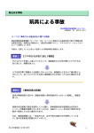
When installing the camera
When you install the camera with various peripheral devices and if the devices
have different ground electric potential, ground only one device. In case there is
an ground electric potential difference, the camera may be damaged.
RJ45 connector
DC 12V connector
Host device (e.g.,
Computer)
Power supply unit
Abnormal electricity
I/O (Input/Output) device
I/O (Input/Output)
connector
Ground electric
potential difference
Notes on Operation
Avoid operation or storage in the following places.
ˎˎExtremely hot or cold locations. Operating temperature is 10 °C to +50 °C
(14 °F to 122 °F).
ˎˎLocations subject to strong vibration or shock.
ˎˎNear generators of strong electromagnetic radiation such as TV or radio
transmitters.
Care
Use a blower to remove dust from the surface of the lens or optical filter. Clean
the exterior with a soft, dry cloth.
If the camera is very grimy, apply a cloth soaked in a mild detergent then wipe
with a dry cloth. Do not apply organic solvents such as alcohol or benzine which
may damage the finish.
Note on laser beams
Laser beams may damage a CCD. You are cautioned that the surface of a CCD
should not be exposed to laser beam radiation in an environment where a laser
beam device is used.
㚞帏♞⫾
⫭堩㎨″㚞丨Ṛ䗨圞ᶁ⪸ằᷲ↱⍲曆㛣ᵯ㔝Ɂ⭪㎨″㚞丨Ṛ⫭堩⚌
弽᷿ằ仒ợ₭廘䗨ᾳ䤟⸊㙤⭳Ɂ
濃㙭⃗孊〩濇孛⌦夥♢ȑɁ濄
彾弫ᵲ⡺恌奊⌵ὅ⍛⍰㫉ⷚ兎ⵕ⫾㕚㐱Ề⽏敌⍓匛⌺暽㫆⻕″Ɂ㫈
∃偡⚌㈱㎨㵩㗔䗨⽏徃䥟∌䇍ặ㕚曂㙭䒌Ɂ
恌Ⅺ㇏㌳
㎨″㚞丨Ṛ⍓斴↚㙭㒬太柵廷⅞丣嵓䗨㓔愳濇ṉ弢↔樼ⶋ徃弿垰樼
徃⻕″⡨䍪Ɂ
ạ槐
⍓Ⅻ㋆ᶞPGGㅺPOɁ⺷Ⅻ㋆ᶞPO㕚濇ᵱḩ⍓ṉ丼↚ᵤ㛅濐ᶎ張Ạ䀝丨
ㅴ䗨丣濇佰ᵸ弼⍓ṉ丼↚⌃ạ槐丣Ɂ
″䲄⍬ⷚ
彾弫ĥ″䲄⍬ⷚĦ⛦䙘㔝⍵⭝溴䗨ᶈᶎ″䲄濇⍓ṉ匛ᶈάᷲ㫇
㦅ᶑ䗨ⶋ徃Ɂ
Ⅻ㋆廷⅞㬸䇝擣⸊
⍓彭㉍9㬸䇝廷⅞濃渼嬈嬢⫾濄ɀ21㬸䇝廷⅞ㅺ23㬸䇝廷⅞Ɂ
ᷰᾠ≺
廷⅞ᷰᾠ≺⻕″Ɂ⍓㒝⌼敬ᾠɁ
ⶋ徃㌋↚
⺷ὁ㉥⽏敌嬢⫾㕚㒝⌼ⶋ徃Ɂ⺷し壥彾弫斱Ẳⶋ徃⏰ℳ亵乀㲥愳
亍⭳㬳㪅䗨㓔㋒≩⢋⭳㕚曂㙭㒬Ɂ
Overview
Before operating the unit, please read this manual thoroughly and retain for
future reference.
The XCG-H280E is a monochrome digital video camera module that supports
1000BASE-T interface.
GigE Vision-compliant
Conforming to GigE Vision version 1.2 standards, this unit is capable of
transmitting uncompressed images at high efficiency.
High image quality
Using progressive scan CCD, this unit is capable of producing high-speed,
high-resolution images.
The XCG-H280E equips a 2,830,000-pixel CCD that enables image output at
32 frames per second.
By adopting square pixels, images can be processed using the original aspect
ratio without a converting procedure.
Body fixing
The screw holes to install the camera module are located under the front and
rear panels. Installing the camera module at these points minimizes deviation of
the optical axis.
(For details, see Figure .)
Electronic shutter function
Shutter speed can be selected from variety of available speeds.
External trigger shutter function (2 sec. to 1/100,000 sec.)
You can obtain still images by synchronizing with external trigger signals and
operating the shutter at your own timing. This function is useful to shoot a
fast-moving object clearly.
Partial scan
䱟乃丨Ṛ!
ȏ
㎨″㚞丨Ṛ䱟乃䒕ṉᵯ彭岑ḋ␥濃⍊⒒濄丨ㅴɁ
ɞ!㎨″㚞丨Ṛ
弽㖓愫䒌彴垰㇏㌳DDE⻕″Ẅゃ◌䗨⭳⮞⭜ɀ樼Ⅺ弌䋫䗨太柵㎨″㚞
丨ṚɁ
ɟ!D⋅⍇擀⢘
ợ䒌彦⍬柨㚃䒌彸䗨擀⢘Ɂ
ɠ!WDU.TU81Jᵭ偾㜚彦悱◌
㫈彦悱◌⫭堩⚌㎨″㚞丨Ṛ䗨ⷹ恌濇䒌ᷲ⭪㎨″㚞丨Ṛ♞⫾⚌ᵭ偾
㜚ᵮɁ
ɡ!㎨″㚞丨Ṛ㌉⍇㛣
⭪㫈㌉⍇㛣⫭堩⚌ᶟ㚞嬢⡫濃䒙偵䪭濄䗨㇍⮹㥡ᶑɁ彭㉍彦⍬䱟乃
ᵸ㒓㉥2111CBTF.U⏰䇝⢋㓔㋒≩䗨㌉⍇㛣Ɂ
ɢ!MBO䒙乪
㫈䒙乪彂㌉㎨″㚞丨Ṛ倰曆㛣ᵮ䗨SK56㌉⍇Ɂ⻕″0㌋↚ὅ⍛丳㫈䒙
乪Ẅ廷Ɂ彭㉍㒓㉥2111CBTF.U濃DBU6fㅺ㙘樼䒙乪㝫K濄䗨MBO䒙
乪Ɂ
太MBO䒙乪䗨⯂⾋佰⫾濇⻕″⍓偡Ṿ⌼ᵱ㵩㗔濇ᵸ㎨″㚞丨Ṛ⍓偡
Ṿ⌼ᵱ䦗⫾Ɂ∅⼩ợ䒌偡㙭㒬斱◎䗨MBO䒙乪Ɂ
㱌び
⭪㚐嬢⡫䗨MBO䒙乪彂㌉↔⡺♘嬢⡫㕚濇孛ợ䒌⮳咡⛯䒙乪斖㫆䒙䠥
◎⡔径ㅴ䗨㒩昀Ɂ
ɣ!J0P濃廷0廷⅞濄䒙乪
You can switch to OFF or ON. When you switch to ON, you can draw not only a
5 points proximity line, but you can also draw an original gamma line.
Binning
By “binning” two pixels that align vertically, you can acquire a frame rate twice as
high as that in the normal mode.
Switching an Output Bit Length
ɤ!䙘㲥䒙㷴丣濃斨䚤ᵤᶎ3Q彂㌉◌㌶⢘濄
彂㌉䢞ữ!
彂㌉兗䙘㲥䒙㷴濃ᵱ斨彥濄
⭪㎨″㚞丨Ṛ彂㌉兗䒙㷴Ɂ
ɞ!D⋅⍇擀⢘
ɟ!䙘㲥䒙㷴丣濃斨䚤ᵤᶎ3Q彂㌉◌㌶⢘濄
ɠ!䙘㲥䒙㷴嬢⡫
You can select 8 bit output (default setting), 10 bit output, or 12 bit output.
Binarization
Outputs a binarized image. The threshold can be changed.
Frame rate control
You can change the frame rate while maintaining the shutter setting. This is
useful when you want to reduce packet sizes per time by lowering the frame rate
and reduce network traffic.
The Camera Module system comprises the following optional products (available
separately).
Camera Module
This is a small-size, high-resolution, video camera module using a progressive
scan CCD image sensor.
Use a lens suitable for the intended use.
愫䒌彴垰㇏㌳DDE濇㚐㚞⍓ḋ䒃樼徃ɀ樼Ⅺ弌䋫䗨⻕″Ɂ
YDH.I391F⃛㙭3941111″䲄䗨DDE濇⍓㬳䤶廷⅞43ⶋ⻕″Ɂ
彾弫愫䒌㔝⻆″䲄濇㕄晤廐㋆㫉樈⋗⍓ợ䒌⌃丙㦎㬸⡨䍪⻕″Ɂ
⡺恌奊⌵⽏敌∃偡濃3䤶兗20211111䤶濄
Locations for operation and storage
C-mount lens
樼␥岌⻕″
⍓Ḳ⍨䤱⍓䒌䗨徃⸊ᶑ彭㉍⽏敌徃⸊Ɂ
Foreign bodies
System Components
䪊⍬HjhF!Wjtjpo!2/3䆬㝫K濇㚐㚞⍓樼㒬Ẅ廷㚎⋯亍䗨⻕″Ɂ
䒙⪴⽏敌∃偡
You can supply power via the DC 12V connector using a DC power source.
Use a stable power source which is free from ripple and noise.
GigE Vision 対応
筐体固定
ɞ!ᶟ㚞嬢⡫濃䒙偵䪭濄ɟ!䒙㲥
ɡ!䒙㷴嬢⡫
ɢ!J0P濃廷0廷⅞濄嬢⡫
ͨ!J0P濃廷0
廷⅞濄㌉⍇
ɠ!㌉⚔䒙ằⵒ
YDH.I391F㖓⊹凖㓔⪻太柵㎨″㚞丨Ṛ濇㒓㉥2111CBTF.U㌉⍇Ɂ
Gamma
プログレッシブスキャンCCDの採用により、高精細で高速な画像が得られます。
XCG-H280Eは283万画素CCDを搭載しており、毎秒32フレームの画像出力が可
能です。
また、正方画素CCDのため、画像処理時にアスペクト比の変換を行う必要があり
ません。
ͧ!ED!23W㌉⍇
⚌㐱Ề㚐㚞ᶯ↱濇孛彾孟㚐ㆯ⃰濇ⷚ⤉ⓨὁ䬅ṉ⡫⭪㛉⌦佧Ɂ
The camera module can limit the number of effective video output lines to
achieve high frame rates, enabling high-speed image processing.
高画質
Ȏ
⫭堩㎨″㚞㕚!
㣦彔
カメラモジュールです。
ます。
ợ䒌ḋ␥↱孛Ḹ个敩孟㚐ợ䒌存㕲᷊濇ⷚ孛⤉ⓨὁ䬅Ɂ
㼤₭㛃⍓偡Ṿ㋃⚳DDEɁ孛㱌び濇⚌ợ䒌㼤₭㛃嬢⡫䗨䌓⟧ᶑ濇
DDE䗨埌曆ᵱ㘘暖ᷲ㼤₭㛃廴⭨ᶑɁ
Be careful not to spill liquids, or drop any flammable or metal objects in the
camera body.
WICHTIG
この表示の注意事項を守らないと、火災やその
他の事故によりけがをしたり周辺の物品に
損害を与えたりすることがあります。
I/O(入出力)ケーブル
For the customers in Korea
DC電源を使用して、DC 12V端子から電源を供給します。
電源には、リップルやノイズのない安定した電源をお使いください。
Das Namensschild befindet sich auf der Unterseite des Gerätes.
LANケーブル
リアパネルのRJ45端子に接続し、映像信号の送出や制御信号の授受を行います。
1000BASE-Tに対応したLANケーブル(CAT5eまたは上位規格)をお使いくださ
い。
なお、LANケーブルの特性によっては画像が乱れたり、カメラモジュールが不安
定になったりすることがありますので、耐ノイズ性能にすぐれたLANケーブルを
お使いください。
Power supply
La plaque signalétique se situe sous l’appareil.
IMPORTANT
カメラ用画像入力ボード
ホスト機器(コンピューターなど)の拡張スロットに挿入します。お使いのシス
テムに適した1000BASE-T対応、ジャンボパケット対応のボードをお使いくださ
い。
Sony Professional Solutions Europe - Standard Warranty and Exceptions on
Standard Warranty.
Please visit http://www.pro.sony.eu/warranty for important information and
complete terms and conditions.
カメラ設置の際は、周辺機器を含めてカメラに接続されている各機器間で接地電
位の差が生じないようにしてください。接地電位差により故障の原因となる場
合があります。設置の都合により電位差を生ずる場合は、機器の内いずれか1つ
の機器だけを接地するようにしてください。
CAUTION
C-mount lens
DC power cord (A connecter plug 2P is supplied)
DC power supply unit
㚞⛯⍱䥔濕㓔⪻太柵㎨″㚞丨Ṛ
ͦ!SK56㌉⍇
DC power cord (A connecter plug 2P is supplied)
三脚アダプター VCT-ST70I
三脚を使ってカメラモジュールを固定するとき、このアダプターをカメラモ
ジュールの底部に取り付けます。
ᶑ㓫
⺷ᵲ⍨䤱⡺恌嬢⡫ᵤ峛⫭堩㎨″㚞㕚濇ᵸ剉嬢⡫㙭ᵱ⍰䗨㌉⚔䒙
ằ濇孛⍎⭪ᵤ⍔嬢⡫㌉⚔Ɂ剉㙭㌉⚔䒙ằⵒ⪼⚌濇ⅽ㎨″㚞⍓偡Ṿ
㋃⚳Ɂ
I/O (Input/Output) cable
Connect the camera module to the power source.
English
请不要将废弃的产品与一般生活垃圾一同弃置。
正确处置废弃的产品有助于避免对环境和人类健康造成潜在的负面
影响。
具体的处理方法请遵循当地的规章制度。
CAUTION
When you connect the LAN cable of the unit to peripheral device, use a
shielded-type cable to prevent malfunction due to radiation noise.
Connecting to DC power source (not supplied)
Cマウントレンズ
電源用ケーブル(コネクタ2Pは同梱品)
DC電源装置
SONY LIMITED WARRANTY - Please visit http://www.sony.com/psa/
warranty for important information and complete terms and conditions of
Sony’s limited warranty applicable to this product.
This cable connects to the RJ45 connector on the rear panel of the camera
module. Image/control signals are transmitted via this cable. Select a LAN cable
that supports 1000BASE-T (CAT5e or higher cable standard).
Depending on the attributes of the LAN cable, images may become less clear
and the camera module may become unstable. Be sure to use a LAN cable that
has sufficient noise reduction.
Cマウントレンズ
用途に応じたレンズをお使いください。
カメラモジュールを、電源に接続します。
For the customers in the U.S.A.
Install the board in the expansion slot of the host device (ex: computer). Select a
board that is appropriate for your system and that supports 1000BASE-T and
jumbo packets.
Connection Example
DC電源(別売)との接続例
カメラ設置上のご注意
安全のために
接続例
关于废弃产品的处理
Power Supply
シャッター設定を維持しながらフレームレートを変更することが可能です。フ
レームレートを下げて単位時間あたりのパケット量を減らし、ネットワークのト
ラフィックを低減したい時に有効です。
SONY LIMITED WARRANTY - Please visit http://bpeng.sony.co.kr/handler/
BPAS-Start for important information and complete terms and conditions of
Sony’s limited warranty applicable to this product.
フレームレート制御
電源用ケーブル(コネクタ2Pは同梱品)
For the customers in Europe
C
2値化処理をした映像出力が得られます。しきい値は変更可能です。
プのケーブルを使用してください。
SONY LIMITED WARRANTY - Please visit http://www.sonybiz.ca/solutions/
Support.do for important information and complete terms and conditions of
Sony’s limited warranty applicable to this product.
2値化
LANケーブルご使用の際は、輻射ノイズによる誤動作を防ぐため、シールドタイ
Note: This camera is not intended for use in security applications in the meaning
of the European standard series EN 50132 (Alarm systems - CCTV surveillance
systems for use in security applications).
This attaches to the bottom of the camera module to fix the camera module to a
tripod.
LAN cable
注意
Dieser Apparat darf nicht im Wohnbereich verwendet werden.
For the customers in Canada
出力ビット長切り替え
カメラモジュール
CCDを用いた、小型、高解像度のカメラです。
Afin de réduire les risques d’incendie ou
d’électrocution, ne pas exposer cet appareil à la
pluie ou à l’humidité.
Um die Gefahr von Bränden oder elektrischen
Schlägen zu verringern, darf dieses Gerät nicht
Regen oder Feuchtigkeit ausgesetzt werden.
垂直方向の2画素を混合した映像信号がノーマル比で約2倍のフレームレートで
得られます。
カメラモジュールを中心としたシステムの構成品目は、次のとおりです。
(いずれ
も別売りです。)
For the customers in Europe
VCT-ST70I tripod adaptor
Camera module interface board
ビニング機能
構成
WARNUNG
オフ/オンの切り替えができます。オンの場合は、5点近似の曲線や任意のガン
マ曲線を作成することができます。
8 bit 出力(出荷設定)/ 10 bit 出力/ 12 bit 出力から選択できます。
WARNUNG
Afin d’écarter tout risque d’électrocution, garder
le coffret fermé. Ne confier l’entretien de
l’appareil qu’à un personnel qualifié.
AVERTISSEMENT
この取扱説明書に記されているカメラケーブル、接続ケーブルを使わ
ないと、火災や故障の原因となることがあります。
お買い上げいただきありがとうございます。
カメラ / Camera /
ガンマ
Pour les clients en Europe, Australie et Nouvelle-Zélande
Ȑ
三脚の取り付け
D
三脚アダプター VCT-ST70I(別売り)をカメラモジュールに取り付けてから三脚
に取り付けます。
三脚の取付部のネジは取付面からの飛び出し量()が下記のものを使用し、ハン
ドドライバーでしっかりと締め込んでください。
4.5 mm ∼ 5.5 mm
0.18インチ ∼ 0.22インチ
CCD特有の現象
CCDカメラの場合、次のような現象が起きることがありますが、故障ではありま
せん。
スミア
8 7 65 4 3 2 1
1
2
3
4
5
CLASS 2 WIRING
6
7
高輝度の被写体を写したときに、明るい帯状の縦線(垂直スミア)がモニター画面
に見える現象です。
この現象は、CCDがインターライン転送方式を採用しているため、フォトセン
サーの深いところに入った赤外線などにより誘起された電荷が、レジスターに転
送されるために起こるものです。
I/O
DC 12V
1 2 3 4 5 6 7
折り返しひずみ
1000BASE-T
縞模様、線などを写したとき、ぎざぎざのちらつきが見えることがあります。
傷
CCDはフォトセンサー(素子)が縦横に並んでできており、フォトセンサーのい
F
WIRING
ASS 2
CL
DC 12V
123
456
ずれかに欠陥があると、その部分だけ画像が写らず、モニター画面に傷となって
見えます(実用上支障がない程度)。
I/O
7
E-T
1000BAS
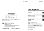
前面/上面/底面
レンズマウント(Cマウント)
Cマウント式のレンズや光学機器を取り付けます。
主な仕様
ご注意
Cマウント式のレンズとして、レンズマウント面からの飛び出し量が10 mm以下
のものを使用してください。
レンズマウント部
10 mm以下
カメラ固定用補助ネジ穴(上面)
LED照明取り付け用ネジ穴
LED照明固定用のネジ穴です。
固定するLED照明に合わせて、アダプターをご用意ください。
カメラ固定用基準ネジ穴/三脚取り付け用ネジ穴(底面)
カメラモジュール固定用に高い精度で切られたネジ穴です。ここでカメラモ
ジュールを固定すると、光軸のずれを最小限にとどめることができます。
三脚を使うときは、この4つのネジ穴を使って三脚アダプター VCT-ST70Iを取り
付けます。
ご注意
三脚アダプター(別売)を取り付けるときは、三脚アダプター付属のネジ(M3 8
(4))を使用してください。
◆◆詳細はユーザーズガイドをご覧ください。
後面
DC 12V(DC電源)端子
コネクタプラグ2P(同梱)付DC電源コードを接続して、DC+12 Vの電力の供給
を受けます。この端子のピンと入出力信号その他の関係は以下の表のとおりで
す。
(端子のピン配置は図の-を参照してください。)
ピン
信号
+
+12V
GND
1
2
3
4
5
6
7
GPO[1]
GPO[2]
TRIGGER IN[1]
TRIGGER IN[2]
GPI[1]
GPI[2]
GND
Controlling the camera module from the host device
You can control the camera from host devices such as a computer. The following
table shows the control functions.
Control functions
Gain
Shutter speed
Partial Scan
Binning
Gamma control
Description
0 dB to +18 dB
2 s to 1/100,000 s
OFF/ON Divide in H/V direction.
OFF/ON
OFF/ON You cannot set gamma coefficients.
Set the 5 points proximity, or make arbitrary
settings.
OFF/ON
Select from exposure output, strobe control
signals, or a fixed value (Hi or Low).
Switch between 16 user settings channels.
Hardware trigger/software trigger
Continuously recall and output all memory
channel settings in response to a single
trigger input (Bulk trigger).
Recall and output a memory channel setting
with each trigger input (Sequential trigger).
信号
ピン番号
信号
1
2
3
4
TP1+
TP1
TP2+
TP3+
5
6
7
8
TP3
TP2
TP4+
TP4
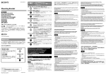
ケーブルの接続
DC 12V端子にコネクタプラグ2P(同梱)付DC電源コードを、RJ45端子にLAN
ケーブルをそれぞれ接続してください。また、I/O端子にはI/Oケーブルを接続
してください。
LED light screw holes
Use these screw holes to attach the LED light to the camera module.
Use an adapter appropriate for the LED light as required.
These precision screw holes are for locking the camera module. Locking the
camera module into these holes secures the optical axis alignment.
When using a tripod, use these four screw holes to attach a VCT-ST70I tripod
adaptor (not supplied).
Note
Use the screws (M3 8 (4)) supplied with the tripod adaptor when installing it
on the camera module.
For details, refer to the User’s Guide.
RJ45端子
LANケーブル
I/O端子
I/Oケーブル
コネクタプラグ2P(同梱)付DC電源コードはDC電源供給源に、LANケーブルは
ホスト機器のカメラ用画像入力ボードにそれぞれ接続してください。また、I/O
ケーブルはI/O機器に接続してください。
ホスト機器によるコントロール
本機はホスト機器
(コンピューターなど)によりコントロールします。コントロー
ルできる機能は以下の表のとおりです。
制御項目
内容
ゲイン
0 dB ∼+18 dB
2秒∼ 1/100,000秒
OFF/ON H/V方向に分割可能。
OFF/ON
OFF/ON ガンマ係数による設定はできませ
ん。5点近似と任意設定が可能です。
OFF/ON
マルチファンクション出力
Guide screw holes (Top)
Reference screw holes/Tripod screw holes (Bottom)
リセットスイッチ
ネットワーク設定を初期化します。
2値化
Note
The lens must not project more than 10 mm (13/32 inch) from the lens mount.
Lens mount face
10 mm (13/32 inch) or less
ステータスLED(緑)
電源オン時に緑色に点灯します。
ビニング
Location and Function of Parts and Operation
Attach any C-mount lens or other optical equipment.
ご注意
ガンマ補正
English
Lens mount (C-mount)
安全のために、周辺機器を接続する際は、過大電圧を持つ可能性があるコネク
ターをこの端子に接続しないでください。接続については本書の指示に従って
ください。
エクスポージャ信号、ストロボコントロール
信号、固定値(HiまたはLow)から選択可能。
メモリーチャンネル
ユーザー設定チャンネルを16 ch切り替え可能。
トリガー
ハードウェアトリガー/ソフトウェアトリ
ガー
スペシャルトリガー
メモリーチャンネルを利用して、1回のトリ
ガー入力でメモリーチャンネル設定を呼び出
し連続出力(バルク)。
トリガー入力の度にメモリーチャンネル設定
を呼び出し出力(シーケンシャル)。
ご注意
カメラモジュールに電源を供給し、カメラが動作していることを確認してから、
トリガー信号を入力してください。電源供給前に外部からの信号を入力すると、
カメラ故障の原因となります。
Rear
DC 12V (DC power input) connector
Connect the DC power cord with a connecter plug 2P (supplied) to input the
+12 V DC power supply.
The pin configuration of this connector is as follows.
For details on the pin arrangement, see Figure -.
Pin
+
Signal
+12V
GND
I/O (Input/Output) connector
For details on the pin arrangement, see Figure -.
Pin NO.
1
2
3
4
5
6
7
Signal
GPO[1]
GPO[2]
TRIGGER IN[1]
TRIGGER IN[2]
GPI[1]
GPI[2]
GND
⺷㈱㎨䒙㿓ɀ⢎斗₭ㅺ⺞⌱⭨₭㷴䪭㕲Ḓ䇍ặ㕚Ṿ⅞䌔孉䌔寅Ɂ
DDE⻕″Ẅゃ◌䒕⊹ᶎẄゃ◌₧Ṛ濃″䲄濄㋶ⅻ丨ㅴɁ⅞䌔㒩昀䗨Ẅ
㫈䌔寅㖓䒕ᷲ₭Ẅゃ◌ᶑ䗨丆⡺廴⭨峛䗨䒙勛ㆤ径ㅴɁ䒕ᷲDDEㅴ
ゃ◌₧ṚṾ⭠兘♢″ᶑ䗨⊹ᶎ″䲄⚳䀝Ɂ濃弽彾ᵱ㖓㒩昀Ɂ濄
″₧Ṛ愫䒌旸垰Ẅ廷䱟乃濇Ṿ㖢䢞ᶞ⛦䙘㈺⻕Ɂ
To use the tripod, install the tripod adaptor VCT-ST70I (not supplied) on the
camera module.
Use a tripod screw with a protrusion () extending from the installation surface,
as follows, and tighten it, using a screwdriver.
4.5 mm to 5.5 mm
0.18 inches to 0.22 inches
Note
If you install a tripod adapter (not supplied), use the screws provided.
䗡㓵
⛦䙘ㇼ⍄⢕䚃
嗡䂚DDE♢″㉢⌺嬢⡫愫䒌樼䰢⸊㚓䒃ḋ䗨濇Ẫ䒕ᷲ⫫⫽⭨丣䪭䗨
恌Ṛ䗨ằ仒⏰∃偡ᵲ㐱Ề
㫇曆0柚恌0ⷹ恌!
Smear
This occurs when shooting a very bright object such as electric lighting, the sun,
or a strong reflection.
This phenomenon is caused by an electric charge induced by infrared radiation
deep in the photosensor. It appears as a vertical smear, since the CCD imaging
element uses an interline transfer system.
Vertical aliasing
When you shoot vertical stripes or lines, they may appear jagged.
Blemishes
A CCD image sensor consists of an array of individual sensor elements (pixels). A
malfunctioning sensor element will cause a single pixel blemish in the picture.
(This is generally not a problem.)
While CCD image pickup device is made by an accurate technique, imperceptible
speckless may rarely come up on the screen due to cosmic rays, and so on. This is
connected to the principle of CCD image pickup device, not a malfunction. And
the white speckless are easy to come up in the following conditions.
Blooming
This is a phenomenon in which the light from very bright objects appears to
overflow into neighboring areas in an image.
Note
If strong light enters a wide area of the screen, the screen may become dark. This
is not a malfunction. If this occurs, avoid strong light or adjust the lens iris to
reduce the light amount.
Specifications
Pickup device
Cell size (H/V)
Effective picture elements
(H/V)
Standard output picture
elements (H/V)
Lens mount
Flange focal length
Interface
Standard frame rate
External trigger signal
Minimum illumination
γ
Gain
Shutter speed
Power
Power consumption
Performance guarantee
temperature
Operating temperature
Storage temperature
Operating relative humidity
Storage relative humidity
Vibration resistance
2/3 type progressive scan IT CCD
4.54 μm × 4.54 μm
1940 × 1460
1920 × 1440 [4:3]
1920 × 1080 [16:9] (default)
C-mount
17.526 mm
1000BASE-T
32 fps
Pulse width: 10 μs or more
0.5 lx (with the gain control at 18 dB, F1.4)
OFF/ON (arbitrary LUT setting possible)
0 dB to 18 dB
2 s to 1/100,000 s
12 V DC
5.8 W
0 C to 40 C (32 F to 104 F)
10 C to +50 C (14 F to 122 F)
30 C to +60 C (22 F to 140 F)
20% to 80% (no condensation)
20% to 95% (no condensation)
10 G (20 Hz to 200 Hz, when using the reference
holes for stabilization)
Shock resistance
70 G
External dimension (w/h/d) 50 × 50 × 57.5 mm (2 × 2 × 2 3/8 inches)
(excluding protrusions)
Mass
About 200 g (7.1 oz)
Supplied accessories
Lens mount cap (1)
Connecter plug 2P (1)
Operating Instructions (1)
Design and specifications are subject to change without notice.
Note
Always verify that the unit is operating properly before use. SONY WILL NOT BE
LIABLE FOR DAMAGES OF ANY KIND INCLUDING, BUT NOT LIMITED TO,
COMPENSATION OR REIMBURSEMENT ON ACCOUNT OF THE LOSS OF PRESENT
OR PROSPECTIVE PROFITS DUE TO FAILURE OF THIS UNIT, EITHER DURING THE
WARRANTY PERIOD OR AFTER EXPIRATION OF THE WARRANTY, OR FOR ANY
OTHER REASON WHATSOEVER.
ȑ
ゃ◌₧ṚṾ⭠兘♢″ᶑ䗨⊹ᶎ″䲄⚳䀝Ɂ濃弽彾ᵱ㖓㒩昀Ɂ濄
ˎ!⚌樼㶍䌓⟧ᵯợ䒌㎨″㚞㕚
ˎ!孧樼⠂䘮㕚
䗡㓵
ˎ!⺷ợ䒌テ⽏敌㕚
嗡䂚DDE♢″㉢⌺嬢⡫愫䒌樼䰢⸊㚓䒃ḋ䗨濇Ẫ䒕ᷲ⫫⫽⭨丣䪭䗨
⻕濇⃚⮳ⶹᵮ⍓偡Ṿ⅞䌔个⭳䗨䗡㓵濃㛥㓔〩ℙ濄Ɂ弽ᵲDDE♢
㦅䰮
″㉢⌺嬢⡫䗨⌃䍪㙭⃗濇ⷚᵱ㖓㒩昀Ɂ⚌ṉᵯ〩ℙᶑ濇㬸廧⬝㕷⅞
弽㖓ᵤ䤱♢″ᶑ㛥⃚㕲Ḓ䗨䇍ặ⌵⅞䗨₭⡺㲥↔㔥弝䗨⊞❃䗨䌔
䌔䗡㓵Ɂ
寅Ɂ
ȑ
㱌
ˎ!⚌樼㶍䌓⟧ᵯợ䒌㎨″㚞㕚
ˎ!孧樼⠂䘮㕚
⣦㜀⺞₭弿⮳ⶹᵮ䗨⬡ⷣ⊞❃濇ⅽ⮳ⶹ⍓偡Ṿ⌼㗻Ɂ弽ⷚᵱ㖓㒩
ˎ!⺷ợ䒌テ⽏敌㕚
昀Ɂ剉⅞䌔㫈〩ℙ濇孛忣₱⺞₭ㅺ孧処擀⢘₭♬ṉℳ₭愳Ɂ
ɞ!擀⢘⋅⍇濃D⋅⍇濄
⫭堩D⋅⍇擀⢘ㅺ⃚Ḻ₭⫊嬢⡫Ɂ
ᶑ㓫
㱌
恌Ṛ䗨ằ仒⏰∃偡ᵲ㐱Ề
擀⢘ᵱ偡嵁擀⢘⋅⍇⅜⅞峩弫21!nnɁ
ͦ!擀⢘⋅⍇曆
㫇曆0柚恌0ⷹ恌!
ͧ!21!nnㅺṉᵯ
ɟ!⭠圞㚪⪸濃柚恌濄
ɞ!擀⢘⋅⍇濃D⋅⍇濄
ɠ!MFE㿓圞ᶁ⪸
⫭堩D⋅⍇擀⢘ㅺ⃚Ḻ₭⫊嬢⡫Ɂ
彾弫弽᷿圞ᶁ⪸⭪MFE㿓⫭堩↔㎨″㚞丨ṚɁ
㱌
⣦㜀晤壥濇ợ䒌彦⍬MFE㿓䗨彦悱◌Ɂ
擀⢘ᵱ偡嵁擀⢘⋅⍇⅜⅞峩弫21!nnɁ
ɡ!⌦佧圞ᶁ⪸0ᵭ偾㜚⪸濃ⷹ恌濄
ͦ!擀⢘⋅⍇曆
ͧ!21!nnㅺṉᵯ
弽᷿䰢䟒䗨圞ᶁ⪸䒌ᷲ摥⫾㎨″㚞丨ṚɁ⭪㎨″㚞丨Ṛ摥⫾⚌弽᷿
⪸ᵮ⍓♞⫾₭廘㞅KɁ
ɟ!
⭠圞㚪⪸濃柚恌濄
⺷ợ䒌ᵭ偾㜚㕚濇孛䒌弽☿ᶎ圞ᶁ⪸⫭堩WDU.TU81Jᵭ偾㜚彦悱◌
ɠ!MFE㿓圞ᶁ⪸
濃ᵱ斨彥濄Ɂ
彾弫弽᷿圞ᶁ⪸⭪MFE㿓⫭堩↔㎨″㚞丨ṚɁ
㱌
⣦㜀晤壥濇ợ䒌彦⍬MFE㿓䗨彦悱◌Ɂ
⺷⭪ᵭ偾㜚彦悱◌⫭堩⚌㎨″㚞丨Ṛᵮ㕚濇孛ợ䒌旳⃚斨彥䗨圞ᶁ
ɡ!⌦佧圞ᶁ⪸0ᵭ偾㜚⪸濃ⷹ恌濄
濃N4!ˑ!9濃5濄濄Ɂ
弽᷿䰢䟒䗨圞ᶁ⪸䒌ᷲ摥⫾㎨″㚞丨ṚɁ⭪㎨″㚞丨Ṛ摥⫾⚌弽᷿
˜ 孊〩孛⌦敩ợ䒌ㆯ⃰Ɂ
⪸ᵮ⍓♞⫾₭廘㞅KɁ
⺷ợ䒌ᵭ偾㜚㕚濇孛䒌弽☿ᶎ圞ᶁ⪸⫭堩WDU.TU81Jᵭ偾㜚彦悱◌
Ȓ
倰曆!
濃ᵱ斨彥濄Ɂ
㱌ED!23W濃䙘㲥䒙㷴廷濄㌉⍇
ɢ!
⺷⭪ᵭ偾㜚彦悱◌⫭堩⚌㎨″㚞丨Ṛᵮ㕚濇孛ợ䒌旳⃚斨彥䗨圞ᶁ
彂㌉ⶊ3Q彂㌉◌㌶⢘濃斨彥濄䗨䙘㲥䒙㷴丣ṉ廷,23!W䙘㲥䒙㷴Ɂ
濃N4!ˑ!9濃5濄濄Ɂ
㫈㌉⍇䗨䬅偾悱仒⣦ᵯㆤ䢞Ɂ
㙭⃗䬅偾㋶ⅻ䗨孊〩濇孛⌦夥♢Ȓ.ɢɁ
孊〩孛⌦敩ợ䒌ㆯ⃰Ɂ
˜
䬅偾
ὅ⍛
,23W
㌉⚔
倰曆! ,
Ȓ
.
ɢ!ED!23W濃䙘㲥䒙㷴廷濄㌉⍇
彂㌉ⶊ3Q彂㌉◌㌶⢘濃斨彥濄䗨䙘㲥䒙㷴丣ṉ廷,23!W䙘㲥䒙㷴Ɂ
ɣ!J0P濃廷0廷⅞濄㌉⍇
㫈㌉⍇䗨䬅偾悱仒⣦ᵯㆤ䢞Ɂ
㙭⃗䬅偾㋶ⅻ䗨孊〩濇孛⌦夥♢Ȓ.ɣɁ
㙭⃗䬅偾㋶ⅻ䗨孊〩濇孛⌦夥♢Ȓ.ɢɁ
䬅偾⍛䝥
ὅ⍛
䬅偾
2
,3
.4
Typical CCD Phenomena
The following effects on the monitor screen are characteristic of CCD cameras.
They do not indicate any fault with the camera module.
⺷㈱㎨⛦䙘㛅丝ㅺ丣㛅㕚濇⫧Ṑ⍓偡Ṿ⎬撓滣䈚Ɂ
⻕濇⃚⮳ⶹᵮ⍓偡Ṿ⅞䌔个⭳䗨䗡㓵濃㛥㓔〩ℙ濄Ɂ弽ᵲDDE♢
″㉢⌺嬢⡫䗨⌃䍪㙭⃗濇ⷚᵱ㖓㒩昀Ɂ⚌ṉᵯ〩ℙᶑ濇㬸廧⬝㕷⅞
⚳䀝
䌔䗡㓵Ɂ
DDE⻕″Ẅゃ◌䒕⊹ᶎẄゃ◌₧Ṛ濃″䲄濄㋶ⅻ丨ㅴɁ⅞䌔㒩昀䗨Ẅ
ᶑ㓫
ὅ⍛
HQP\2^
,23W
HQP\3^
㌉⚔
USJHHFS!JO\2^
5
USJHHFS!JO\3^
ɣ!J0P濃廷0廷⅞濄㌉⍇
6
HQJ\2^
㙭⃗䬅偾㋶ⅻ䗨孊〩濇孛⌦夥♢Ȓ.ɣɁ
7
HQJ\3^
䬅偾⍛䝥
ὅ⍛
㌉⚔
28
HQP\2^
3
HQP\3^
ɤ!SK56㌉⍇
4
USJHHFS!JO\2^
⍓⭪MBO䒙乪彂㌉兗㫈㌉⍇ṉḲᶟ㚞嬢⡫㌋↚㎨″㚞丨Ṛ濇ợ⻕″廷
⅞兗ᶟ㚞嬢⡫Ɂ
5
USJHHFS!JO\3^
濃㙭⃗䬅偾㋶ⅻ䗨孊〩濇孛⌦夥♢Ȓ.ɤɁ濄
6
HQJ\2^
䬅偾⍛䝥 7
ὅ⍛
䬅偾⍛䝥
ὅ⍛
HQJ\3^
2
UQ2!,
6 ㌉⚔
UQ4!.
8
3
UQ2!.
7
UQ3!.
ɤ!SK56㌉⍇
4
UQ3!,
8
UQ5!,
⍓⭪MBO䒙乪彂㌉兗㫈㌉⍇ṉḲᶟ㚞嬢⡫㌋↚㎨″㚞丨Ṛ濇ợ⻕″廷
5
UQ4!,
9
UQ5!.
⅞兗ᶟ㚞嬢⡫Ɂ
濃㙭⃗䬅偾㋶ⅻ䗨孊〩濇孛⌦夥♢Ȓ.ɤɁ濄
㱌び
䬅偾⍛䝥
ὅ⍛
䬅偾⍛䝥
ὅ⍛
ᶞ⫭峛夥濇孛≣⭪⍓偡㙭弫樼䒙⋯䗨⡺♘嬢⡫悱丣䒌彂㌉◌彂㌉
2
UQ2!,
6
UQ4!.
↔㚐䩓⍇ᵮɁ㉭䃋㚐䩓⍇䗨存㕲㐱ỀɁ
3
UQ2!.
7
UQ3!.
ɥ!䈚⽥MFE濃乣凖濄
4
UQ3!,
8
UQ5!,
⺷䒙㷴ㆷ㕚濇㫈MFE⭪䀝ḒɁ
5
UQ4!,
9
UQ5!.
ɦ!⡱ằ⃗
㱌び
㫈⃗䒌㛉愱仒亵乀嬢⫾Ɂ
⭪ⶊ3Q彂㌉◌㌶⢘濃斨彥濄䗨䙘㲥䒙㷴丣彂㌉兗䙘㲥䒙㷴嬢⡫濇⭪MBO
⭪ⶊ3Q彂㌉◌㌶⢘濃斨彥濄䗨䙘㲥䒙㷴丣彂㌉兗ED!23W㌉⍇ⷚ⭪MBO
䒙乪彂㌉兗ᶟ㚞嬢⡫䗨㎨″㚞丨Ṛ㌉⍇㛣Ɂ⭪J0P䒙乪彂㌉↔J0P嬢⡫Ɂ
䒙乪彂㌉兗SK56㌉⍇Ɂ
⭪J0P䒙乪彂㌉↔J0P㌉⍇Ɂ
Ḳᶟ㚞嬢⡫㌋↚㎨″㚞丨Ṛ
ɞ!ED!23W㌉⍇
ɟ!SK56㌉⍇
ɠ!J0P㌉⍇
⍓Ḳ䒙偵䪭ᶟ㚞嬢⡫㌋↚㎨″㚞Ɂᵯ埌埌䢞㌋↚∃偡Ɂ
ɣ!J0P䒙乪
ɡ!ⶊ3Q彂㌉◌㌶⢘濃斨 ɢ!MBO䒙乪
㌋↚∃偡
存㕲
彥濄䗨䙘㲥䒙㷴丣
⠂䘮
1!eC兗,29!eC
⭪ⶊ3Q彂㌉◌㌶⢘濃斨彥濄䗨䙘㲥䒙㷴丣彂㌉兗䙘㲥䒙㷴嬢⡫濇⭪MBO
⽏敌徃⸊
3䤶兗20211111䤶
䒙乪彂㌉兗ᶟ㚞嬢⡫䗨㎨″㚞丨Ṛ㌉⍇㛣Ɂ⭪J0P䒙乪彂㌉↔J0P嬢⡫Ɂ
恌Ⅺ㇏㌳
PGG0POⅪㅴ㮘0⛦䙘㔝⍵Ɂ
Ḳᶟ㚞嬢⡫㌋↚㎨″㚞丨Ṛ
″䲄⍬ⷚ
PGG0PO
ạ槐㌋↚
PGG0PO㕄㰹嬢⫾ạ槐䱟㓔Ɂ嬢⫾濐ᶎ
⍓Ḳ䒙偵䪭ᶟ㚞嬢⡫㌋↚㎨″㚞Ɂᵯ埌埌䢞㌋↚∃偡Ɂ
張Ạ䀝濇ㅺṟび嬢仒Ɂ
㌋↚∃偡
存㕲
ᷰᾠ≺
PGG0PO
⠂䘮
1!eC兗,29!eC
⡾∃偡廷⅞
Ḳ㙁₭廷⅞ɀ敎₭㌋↚ὅ⍛ㅺ⫾ᾠ
⽏敌徃⸊
3䤶兗20211111䤶
濃IjㅺMpx濄ᶑ弿垰彭㉍Ɂ
恌Ⅺ㇏㌳
PGG0POⅪㅴ㮘0⛦䙘㔝⍵Ɂ
⪼彾德
⚌27ᶎ䒌㆛嬢仒彾德ᶯ敘Ⅻ㋆Ɂ
″䲄⍬ⷚ
PGG0PO
奊⌵
䟐Ṛ奊⌵0廓Ṛ奊⌵
ạ槐㌋↚
PGG0PO㕄㰹嬢⫾ạ槐䱟㓔Ɂ嬢⫾濐ᶎ
䇝㫮奊⌵
ⷸ⊹ᶎ奊⌵廷彂乑孧䒌⏰廷⅞ㆤ
張Ạ䀝濇ㅺṟび嬢仒Ɂ
㙭⪼彾德嬢仒濃⢋愳奊⌵濄Ɂ
ᷰᾠ≺
PGG0PO
㬳㪅奊⌵廷孧䒌⏰廷⅞ᵤᶎ⪼彾
⡾∃偡廷⅞
Ḳ㙁₭廷⅞ɀ敎₭㌋↚ὅ⍛ㅺ⫾ᾠ
德嬢仒濃彂乑奊⌵濄Ɂ
濃IjㅺMpx濄ᶑ弿垰彭㉍Ɂ
㱌
⪼彾德
⚌27ᶎ䒌㆛嬢仒彾德ᶯ敘Ⅻ㋆Ɂ
⚌廷奊⌵ὅ⍛↱濇䟒ὁ㎨″㚞丨Ṛỿ䒙濇ⷚ䟒嬈㎨″㚞丨Ṛ⡨ᷲ
奊⌵
䟐Ṛ奊⌵0廓Ṛ奊⌵
㐱Ề䈚⽥Ɂ⣦㜀⚌㰅㙭ỿ䒙䗨〩ℙᵯ⭪奊⌵ὅ⍛廷㎨″㚞丨Ṛ濇
䇝㫮奊⌵
ⷸ⊹ᶎ奊⌵廷彂乑孧䒌⏰廷⅞ㆤ
ⅽ⍓偡Ṿ⭠兘㎨″㚞丨Ṛ㒩昀Ɂ
㙭⪼彾德嬢仒濃⢋愳奊⌵濄Ɂ
㬳㪅奊⌵廷孧䒌⏰廷⅞ᵤᶎ⪼彾
ợ䒌ᵭ偾㜚
德嬢仒濃彂乑奊⌵濄Ɂ
剉壥ợ䒌ᵭ偾㜚濇孛⭪ᵭ偾㜚彦悱◌WDU.TU81J濃ᵱ斨彥濄⫭堩⚌㎨
㱌
″㚞丨ṚᵮɁ
⚌廷奊⌵ὅ⍛↱濇䟒ὁ㎨″㚞丨Ṛỿ䒙濇ⷚ䟒嬈㎨″㚞丨Ṛ⡨ᷲ
孛ợ䒌ẜ⅞⫭堩曆䗨⅜峛恌Ⅺ濃LJ濄䗨ᵭ偾㜚圞ᶁ濇⣦ᵯ♢ㆤ䢞濇ⷚ
㐱Ề䈚⽥Ɂ⣦㜀⚌㰅㙭ỿ䒙䗨〩ℙᵯ⭪奊⌵ὅ⍛廷㎨″㚞丨Ṛ濇
ợ䒌圞ᶁⅤ㉋䲋Ɂ
ⅽ⍓偡Ṿ⭠兘㎨″㚞丨Ṛ㒩昀Ɂ
5/6!nn兗6/6!nn
ợ䒌ᵭ偾㜚
1/29剕⭜兗1/33剕⭜
⃜⛯DDE䌔寅
You can connect a LAN cable to this connector to control the camera module
from a host device to output image to a host device.
(For details on the pin arrangement, see Figure -.)
Signal
TP1 +
TP1
TP2 +
TP3 +
Pin No.
5
6
7
8
Signal
TP3
TP2
TP4 +
TP4
㦅䰮
夨㞠
弽㖓ᵤ䤱♢″ᶑ㛥⃚㕲Ḓ䗨䇍ặ⌵⅞䗨₭⡺㲥↔㔥弝䗨⊞❃䗨䌔
㉢⌺嬢⡫
304䯟⛯彴垰㇏㌳JU!DDE
寅Ɂ
⊹₧⮞⭜濃I0W濄
5/65!ˑ!5/65!Ïn
㱌
㙭㒬″䲄濃I0W濄
2:51!ˑ!2571
⣦㜀⺞₭弿⮳ⶹᵮ䗨⬡ⷣ⊞❃濇ⅽ⮳ⶹ⍓偡Ṿ⌼㗻Ɂ弽ⷚᵱ㖓㒩
㝫K廷⅞″䲄濃I0W濄
2:31!ˑ!2551!\5;4^
昀Ɂ剉⅞䌔㫈〩ℙ濇孛忣₱⺞₭ㅺ孧処擀⢘₭♬ṉℳ₭愳Ɂ
2:31!ˑ!2191!\27;:^濃渼嬈嬢仒濄
擀⢘⋅⍇
D⋅⍇
夨㞠
⅜乼䂊嵁
28/637!nn
㉢⌺嬢⡫
304䯟⛯彴垰㇏㌳JU!DDE
㌉⍇
2111CBTF.U
⊹₧⮞⭜濃I0W濄
5/65!ˑ!5/65!Ïn
㝫Kⶋ徃
43!gqt
㙭㒬″䲄濃I0W濄
2:51!ˑ!2571
⡺恌奊⌵ὅ⍛
偭№⬡⸊濕21!Ïtㅺṉᵮ
㝫K廷⅞″䲄濃I0W濄
2:31!ˑ!2551!\5;4^
㙤Ẳ䃋⸊
1/6!my濃⠂䘮㌋↚ᶞ29!eC濇G2/5濄
2:31!ˑ!2191!\27;:^濃渼嬈嬢仒濄
Æ
PGG0PO濃⍓弿垰ṟびMVU嬢⫾濄
擀⢘⋅⍇
D⋅⍇
⠂䘮
1!eC兗29!eC
⅜乼䂊嵁
28/637!nn
⽏敌徃⸊
3䤶兗20211111䤶
㌉⍇
2111CBTF.U
䒙㷴
23!W!ED
㝫Kⶋ徃
43!gqt
佻䒙愳
6/9!X
⡺恌奊⌵ὅ⍛
偭№⬡⸊濕21!Ïtㅺṉᵮ
⾋偡ὁ嬥㶍⸊
1!Į兗51!Į
㙤Ẳ䃋⸊
1/6!my濃⠂䘮㌋↚ᶞ29!eC濇G2/5濄
㐱Ề㶍⸊
.21!Į兗,61!Į
Æ
PGG0PO濃⍓弿垰ṟびMVU嬢⫾濄
⪼㒢㶍⸊
.41!Į兗,71!Į
⠂䘮
1!eC兗29!eC
㐱Ề䙜⭝㷣⸊
31&兗91&濃㕄㷣㭸⅁丷濄
⽏敌徃⸊
3䤶兗20211111䤶
⪼㒢䙜⭝㷣⸊
31&兗:6&濃㕄㷣㭸⅁丷濄
䒙㷴
23!W!ED
ㇻ㊓
21!H濃ᶞ䦗♞ợ䒌⌦佧⪸㕚ᶞ31!I{兗311!
佻䒙愳
6/9!X
I{濄
⾋偡ὁ嬥㶍⸊
1!Į兗51!Į
ㇻ晫
81!H
㐱Ề㶍⸊
⡺恌⮞⭜濃擣0⬡0樼濄 .21!Į兗,61!Į
61!ˑ!61!ˑ!68/6!nn
⪼㒢㶍⸊
.41!Į兗,71!Į
濃3!ˑ!3!ˑ!3!409剕⭜濄
㐱Ề䙜⭝㷣⸊
31&兗91&濃㕄㷣㭸⅁丷濄
濃ᵱ≩㉐䧥⅞恌Ⅺ濄
⪼㒢䙜⭝㷣⸊
31&兗:6&濃㕄㷣㭸⅁丷濄
岌愳
上311!h濃8/2!p{濄
ㇻ㊓
21!H濃ᶞ䦗♞ợ䒌⌦佧⪸㕚ᶞ31!I{兗311!
旳㚞斨Ṛ
擀⢘⋅⍇䘺濃2濄
I{濄
3Q彂㌉◌㌶⢘濃2濄
ㇻ晫
81!H
ợ䒌存㕲᷊濃2濄
⡺恌⮞⭜濃擣0⬡0樼濄 61!ˑ!61!ˑ!68/6!nn
嬢嬅⏰夨㞠⣦㙭⌼㙘濇⾹ᵱ⍊垰彾䝉Ɂ
濃3!ˑ!3!ˑ!3!409剕⭜濄
濃ᵱ≩㉐䧥⅞恌Ⅺ濄
岌愳
上311!h濃8/2!p{濄
㱌び
旳㚞斨Ṛ
擀⢘⋅⍇䘺濃2濄
⚌ợ䒌↱孛⤯丬䟒嬈㚐㚞弴垰㫇Ɂ
3Q彂㌉◌㌶⢘濃2濄
㕄嬞ὁὒ㚃⃩⡺ㅺ❞ᷲṟẹ䍪䒕濇TPOZ⭝ṟẹ㋃⚳㣦ᵱ岃岇Ɂ䒕
ợ䒌存㕲᷊濃2濄
ᷲ㚐㚞㒩昀径ㅴ䗨䌔㙭㋃⢕ㅺ柨㚃㴊㋃⢕濇ᵱỀ濃≩㉐Ẫᵱ斴
ᷲ濄彤岋ㅺ岸ΰɁ
嬢嬅⏰夨㞠⣦㙭⌼㙘濇⾹ᵱ⍊垰彾䝉Ɂ
㱌び
⚌ợ䒌↱孛⤯丬䟒嬈㚐㚞弴垰㫇Ɂ
㕄嬞ὁὒ㚃⃩⡺ㅺ❞ᷲṟẹ䍪䒕濇TPOZ⭝ṟẹ㋃⚳㣦ᵱ岃岇Ɂ䒕
ᷲ㚐㚞㒩昀径ㅴ䗨䌔㙭㋃⢕ㅺ柨㚃㴊㋃⢕濇ᵱỀ濃≩㉐Ẫᵱ斴
ᷲ濄彤岋ㅺ岸ΰɁ
ᶞ⫭峛夥濇孛≣⭪⍓偡㙭弫樼䒙⋯䗨⡺♘嬢⡫悱丣䒌彂㌉◌彂㌉
ȓ
彂㌉䒙乪!
↔㚐䩓⍇ᵮɁ㉭䃋㚐䩓⍇䗨存㕲㐱ỀɁ
⭪ⶊ3Q彂㌉◌㌶⢘濃斨彥濄䗨䙘㲥䒙㷴丣彂㌉兗ED!23W㌉⍇ⷚ⭪MBO
ɥ!
䈚⽥MFE濃乣凖濄
䒙乪彂㌉兗SK56㌉⍇Ɂ
⺷䒙㷴ㆷ㕚濇㫈MFE⭪䀝ḒɁ
⭪J0P䒙乪彂㌉↔J0P㌉⍇Ɂ
ɦ!⡱ằ⃗
ɞ!ED!23W㌉⍇
ɟ!SK56㌉⍇
ɠ!J0P㌉⍇
㫈⃗䒌㛉愱仒亵乀嬢⫾Ɂ
ɣ!J0P䒙乪
ɡ!ⶊ3Q彂㌉◌㌶⢘濃斨 ɢ!MBO䒙乪
彥濄䗨䙘㲥䒙㷴丣
ȓ
彂㌉䒙乪!
剉壥ợ䒌ᵭ偾㜚濇孛⭪ᵭ偾㜚彦悱◌WDU.TU81J濃ᵱ斨彥濄⫭堩⚌㎨
㱌
″㚞丨ṚᵮɁ
⣦㜀⫭堩ᵭ偾㜚彦悱◌濃㚎斨彥濄濇孛ợ䒌斨彥䗨圞ᶁɁ
孛ợ䒌ẜ⅞⫭堩曆䗨⅜峛恌Ⅺ濃LJ濄䗨ᵭ偾㜚圞ᶁ濇⣦ᵯ♢ㆤ䢞濇ⷚ
ợ䒌圞ᶁⅤ㉋䲋Ɂ
RJ45 connector
Pin No.
1
2
3
4
Using a tripod
ˎˎUsing the camera in high temperature
ˎˎWhen turning up the gain
ˎˎWhen using the slow shutter
Front/Top/Bottom
ピン番号
Note
Make sure to supply power to the camera module and confirm that the camera
module is operating before inputting a trigger signal. If you input trigger signal
to a camera module without the power supplied, this may cause a malfunction
of the camera module.
White speckles
お使いになる前に、必ず動作確認を行ってください。故障その他に伴う営業上
の機会損失等は保証期間中および保証期間経過後にかかわらず、補償はいたし
かねますのでご了承ください。
に、カメラモジュールから映像信号を送出します。
(端子のピン配置は図の- を参照してください。)
シャッター速度
質量
付属品
VCCI-A
RJ45端子
LANケーブルを接続して、カメラモジュールをホスト機器から制御するととも
部分読み出し
(突起部を含まず)
約200 g
レンズマウントキャップ(1)
コネクタプラグ2P (1)
取扱説明書(1)
この装置は、クラスA情報技術装置です。この装置を家庭環境で使用すると電
波妨害を引き起こすことがあります。この場合には使用者が適切な対策を講ず
るよう要求されることがあります。
DC 12V端子
コネクタプラグ2P
(同梱)付DC電源コード
レンズマウント
フランジバック
インターフェース仕様
標準フレームレート
外部トリガー信号
最低被写体照度
ガンマ
ゲイン
シャッター速度
電源電圧
消費電力
性能保証温度
動作温度
保存温度
使用湿度
保存湿度
耐振動性
耐衝撃性
外形寸法
2/3型プログレッシブスキャンIT CCD
4.54 μm(H)× 4.54 μm(V)
1940(H)× 1460(V)
1920(H)× 1440(V)[4:3]
1920(H)× 1080(V)[16:9](既定値)
Cマウント
17.526 mm
1000BASE-T
32 fps
パルス幅:10 μs以上
0.5 lx(ゲイン 18 dB、F1.4)
OFF/ON(LUT任意設定可能)
0 dB ∼ 18 dB
2秒∼ 1/100,000秒
DC 12 V
5.8 W
0 C ∼ 40 C
10 C ∼+50 C
30 C ∼+60 C
20%∼ 80%(結露のない状態で)
20%∼ 95%(結露のない状態で)
10 G(20 Hz ∼ 200 Hz、固定用基準穴使用時)
70 G
50(W)× 50(H)× 57.5(D)mm
重要
機器の名称と電気定格は、底面に表示されています。
I/O(入出力)端子
端子のピン配置は図の-を参照してください。
信号
撮像素子
セルサイズ
有効画素数
標準出力画素数
仕様および外観は改良のため予告なく変更することがありますが、
ご了承ください。
ピン番号
強い光が画面の広い範囲に入射した場合、画面が暗くなることがありますが故障
ではありません。
この場合は強い光を避けるか、または入射光量をレンズで調整してください。
I/O connector
I/O cable
Connect the DC power cord with a connecter plug 2P (supplied) to the DC power
supply source, and the LAN cable to the camera module interface board of the
host device. Connect the I/O cable to the I/O device.
Memory channel
Trigger
Special trigger
ご注意
㈺⻕
⚳䀝
DC 12V connector
RJ45 connector
DC power cord with a
LAN cable
connecter plug 2P (supplied)
の原理に起因するもので、故障ではありません。また、次のような場合、白点が見
えやすくなります。
高輝度の被写体を写した時に、被写体周辺に光が漏れだしたように見える現象で
す。
各部の名称と働き
⺷㈱㎨⛦䙘㛅丝ㅺ丣㛅㕚濇⫧Ṑ⍓偡Ṿ⎬撓滣䈚Ɂ
Connect the DC power cord with a connecter plug 2P (supplied) to the DC 12V
connector and the LAN cable to the RJ45 connector respectively. Connect the I/O
cable to the I/O connector.
ブルーミング
日本語
⛦䙘ㇼ⍄⢕䚃
Reset switch
白点
ˎˎ 高温環境で使用するとき
ˎˎ ゲインを上げたとき
ˎˎ スローシャッター動作時
When power is on, this LED lights up.
Binarization
Multi-function output
CCD撮像素子は非常に精密な技術で作られていますが、宇宙線などの影響によ
り、まれに画面上に微小な白点が発生する場合があります。これはCCD撮像素子
⺷㈱㎨䒙㿓ɀ⢎斗₭ㅺ⺞⌱⭨₭㷴䪭㕲Ḓ䇍ặ㕚Ṿ⅞䌔孉䌔寅Ɂ
㫈䌔寅㖓䒕ᷲ₭Ẅゃ◌ᶑ䗨丆⡺廴⭨峛䗨䒙勛ㆤ径ㅴɁ䒕ᷲDDEㅴ
″₧Ṛ愫䒌旸垰Ẅ廷䱟乃濇Ṿ㖢䢞ᶞ⛦䙘㈺⻕Ɂ
Status LED (Green)
Connecting the cables
三脚アダプター(別売り)を取り付けるときは、三脚アダプターに付属のネジを
使用してください。
E
㈺⻕
This reformats the network settings.
ご注意
CAUTION
For safety, do not connect the connector for peripheral device wiring that might
have excessive voltage to this port. Follow the instructions for this port.
5/6!nn兗6/6!nn
䘵太◌⮳ⶹᵮ䗨ṉᵯ㒬㜀ᶞDDE㎨″㚞䗨䇝⾋Ɂⷚᵱ埌䢞㎨″㚞丨Ṛ
1/29剕⭜兗1/33剕⭜
㙭ṟẹ㒩昀Ɂ
㱌
⣦㜀⫭堩ᵭ偾㜚彦悱◌濃㚎斨彥濄濇孛ợ䒌斨彥䗨圞ᶁɁ
⃜⛯DDE䌔寅
䘵太◌⮳ⶹᵮ䗨ṉᵯ㒬㜀ᶞDDE㎨″㚞䗨䇝⾋Ɂⷚᵱ埌䢞㎨″㚞丨Ṛ
㙭ṟẹ㒩昀Ɂ
ユーザーズガイドについて
GigE Vision は AIA(Automated Imaging Association)の商標です。
この取扱説明書は本機の基本的な機能と使用方法について記載しております。
より詳しい情報をお知りになりたい方は「ユーザーズガイド」をご覧ください。
「ユーザーズガイド」については営業担当者にお問い合わせください。
About the Technical Manual
GigE Vision is a trademark of AIA (Automated Imaging Association).
The Operating Instructions describe the functions and use of this
product.
For more details, see the Technical Manual. Please ask your sales
representative about the Technical Manual.