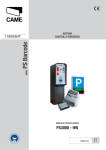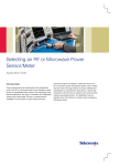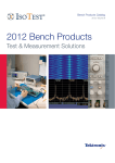
1
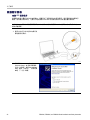
x
PSM3000, PSM4000, and PSM5000 Series
RF and Microwave Power Sensors/Meters
Installation and Safety
ZZZ
Instructions
*P071295801*
071-2958-01
xx
PSM3000, PSM4000, and PSM5000 Series
RF and Microwave Power Sensors/Meters
Installation and Safety
ZZZ
Instructions
www.tektronix.com
071-2958-01
Copyright © Tektronix. All rights reserved. Licensed software products are owned by Tektronix or its subsidiaries or suppliers, and are
protected by national copyright laws and international treaty provisions.
Tektronix products are covered by U.S. and foreign patents, issued and pending. Information in this publication supersedes that in all
previously published material. Specifications and price change privileges reserved.
TEKTRONIX and TEK are registered trademarks of Tektronix, Inc.
Contacting Tektronix
Tektronix, Inc.
14150 SW Karl Braun Drive
P.O. Box 500
Beaverton, OR 97077
USA
For product information, sales, service, and technical support:
In North America, call 1-800-833-9200.
Worldwide, visit www.tektronix.com to find contacts in your area.
Warranty
Tektronix warrants that this product will be free from defects in materials and workmanship for a period of one (1) year from the date of
shipment. If any such product proves defective during this warranty period, Tektronix, at its option, either will repair the defective
product without charge for parts and labor, or will provide a replacement in exchange for the defective product. Parts, modules and
replacement products used by Tektronix for warranty work may be new or reconditioned to like new performance. All replaced
parts, modules and products become the property of Tektronix.
In order to obtain service under this warranty, Customer must notify Tektronix of the defect before the expiration of the warranty period
and make suitable arrangements for the performance of service. Customer shall be responsible for packaging and shipping the
defective product to the service center designated by Tektronix, with shipping charges prepaid. Tektronix shall pay for the return of the
product to Customer if the shipment is to a location within the country in which the Tektronix service center is located. Customer shall
be responsible for paying all shipping charges, duties, taxes, and any other charges for products returned to any other locations.
This warranty shall not apply to any defect, failure or damage caused by improper use or improper or inadequate maintenance and
care. Tektronix shall not be obligated to furnish service under this warranty a) to repair damage resulting from attempts by personnel
other than Tektronix representatives to install, repair or service the product; b) to repair damage resulting from improper use or
connection to incompatible equipment; c) to repair any damage or malfunction caused by the use of non-Tektronix supplies; or
d) to service a product that has been modified or integrated with other products when the effect of such modification or integration
increases the time or difficulty of servicing the product.
THIS WARRANTY IS GIVEN BY TEKTRONIX WITH RESPECT TO THE PRODUCT IN LIEU OF ANY OTHER WARRANTIES,
EXPRESS OR IMPLIED. TEKTRONIX AND ITS VENDORS DISCLAIM ANY IMPLIED WARRANTIES OF MERCHANTABILITY OR
FITNESS FOR A PARTICULAR PURPOSE. TEKTRONIX' RESPONSIBILITY TO REPAIR OR REPLACE DEFECTIVE PRODUCTS
IS THE SOLE AND EXCLUSIVE REMEDY PROVIDED TO THE CUSTOMER FOR BREACH OF THIS WARRANTY. TEKTRONIX
AND ITS VENDORS WILL NOT BE LIABLE FOR ANY INDIRECT, SPECIAL, INCIDENTAL, OR CONSEQUENTIAL DAMAGES
IRRESPECTIVE OF WHETHER TEKTRONIX OR THE VENDOR HAS ADVANCE NOTICE OF THE POSSIBILITY OF SUCH
DAMAGES.
[W2 – 15AUG04]
Table of Contents
Table of Contents
Preface .. . .. . .. . .. . .. . .. . .. . .. . .. . .. . .. . .. . .. . .. . .. . .. . .. . .. . .. . .. . .. . .. . .. . .. . .. . .. . .. . .. . .. . .. . .. . .. . .. . .. . .. . .. . .. . .. . .. . .. . .. . .. . .. .
Products . . .. . .. . .. . .. . .. . .. . .. . .. . .. . .. . .. . .. . .. . .. . .. . .. . .. . .. . .. . .. . .. . .. . .. . .. . .. . .. . .. . .. . .. . .. . .. . .. . .. . .. . .. . .. . .. . .. . .. . .. .
Accessories . .. . .. . .. . .. . .. . .. . .. . .. . .. . .. . .. . .. . .. . .. . .. . .. . .. . .. . .. . .. . .. . .. . .. . .. . .. . .. . .. . .. . .. . .. . .. . .. . .. . .. . .. . .. . .. . .. . . . .
Where To Find More Information .. . .. . .. . .. . .. . .. . .. . .. . .. . .. . .. . .. . .. . .. . .. . .. . .. . .. . .. . .. . .. . .. . .. . .. . .. . .. . .. . .. . .. . .. . .. . .. .
General Safety Summary . .. . .. . .. . .. . .. . .. . .. . .. . .. . .. . .. . .. . .. . .. . .. . .. . .. . .. . .. . .. . .. . .. . .. . .. . .. . .. . .. . .. . .. . .. . .. . .. . .. . .. . .. . . . .
Compliance Information .. . .. . .. . .. . .. . .. . .. . .. . .. . .. . .. . .. . .. . .. . .. . .. . .. . .. . .. . .. . .. . .. . .. . .. . .. . .. . .. . .. . .. . .. . .. . .. . .. . .. . .. . . . . .. .
EMC Compliance. . .. . .. . .. . .. . .. . .. . .. . .. . .. . .. . .. . .. . .. . .. . .. . .. . .. . .. . .. . .. . .. . .. . .. . .. . .. . .. . .. . .. . .. . .. . .. . .. . .. . .. . .. . .. . .. .
Environmental Considerations.. . .. . .. . .. . .. . .. . .. . .. . .. . .. . .. . .. . .. . .. . .. . .. . .. . .. . .. . .. . .. . .. . .. . .. . .. . .. . .. . .. . .. . .. . .. . .. . .. .
Operating Requirements . . .. . .. . .. . .. . .. . .. . .. . .. . .. . .. . .. . .. . .. . .. . .. . .. . .. . .. . .. . .. . .. . .. . .. . .. . .. . .. . .. . .. . .. . .. . .. . .. . .. . .. . .. . .. .
Electrical Ratings. . .. . .. . .. . .. . .. . .. . .. . .. . .. . .. . .. . .. . .. . .. . .. . .. . .. . .. . .. . .. . .. . .. . .. . .. . .. . .. . .. . .. . .. . .. . .. . .. . .. . .. . .. . .. . .. .
Environmental Characteristics.. . .. . .. . .. . .. . .. . .. . .. . .. . .. . .. . .. . .. . .. . .. . .. . .. . .. . .. . .. . .. . .. . .. . .. . .. . .. . .. . .. . .. . .. . .. . .. . .. .
Physical Characteristics .. . .. . .. . .. . .. . .. . .. . .. . .. . .. . .. . .. . .. . .. . .. . .. . .. . .. . .. . .. . .. . .. . .. . .. . .. . .. . .. . .. . .. . .. . .. . .. . .. . .. . .. .
Connectors. . .. . .. . .. . .. . .. . .. . .. . .. . .. . .. . .. . .. . .. . .. . .. . .. . .. . .. . .. . .. . .. . .. . .. . .. . .. . .. . .. . .. . .. . .. . .. . .. . .. . .. . .. . .. . .. . .. . . . . .. . .. .
RF/Microwave Input Connectors .. . .. . .. . .. . .. . .. . .. . .. . .. . .. . .. . .. . .. . .. . .. . .. . .. . .. . .. . .. . .. . .. . .. . .. . .. . .. . .. . .. . .. . .. . .. . .. .
Trigger Connectors.. . .. . .. . .. . .. . .. . .. . .. . .. . .. . .. . .. . .. . .. . .. . .. . .. . .. . .. . .. . .. . .. . .. . .. . .. . .. . .. . .. . .. . .. . .. . .. . .. . .. . .. . .. . .. .
USB Connector. .. . .. . .. . .. . .. . .. . .. . .. . .. . .. . .. . .. . .. . .. . .. . .. . .. . .. . .. . .. . .. . .. . .. . .. . .. . .. . .. . .. . .. . .. . .. . .. . .. . .. . .. . .. . .. . .. .
Getting Started. .. . .. . .. . .. . .. . .. . .. . .. . .. . .. . .. . .. . .. . .. . .. . .. . .. . .. . .. . .. . .. . .. . .. . .. . .. . .. . .. . .. . .. . .. . .. . .. . .. . .. . .. . .. . .. . . . . .. . ..
Install the Software.. . .. . .. . .. . .. . .. . .. . .. . .. . .. . .. . .. . .. . .. . .. . .. . .. . .. . .. . .. . .. . .. . .. . .. . .. . .. . .. . .. . .. . .. . .. . .. . .. . .. . .. . .. . . .
Connect to a Computer . .. . .. . .. . .. . .. . .. . .. . .. . .. . .. . .. . .. . .. . .. . .. . .. . .. . .. . .. . .. . .. . .. . .. . .. . .. . .. . .. . .. . .. . .. . .. . .. . .. . .. . ..
Functional Check. . .. . .. . .. . .. . .. . .. . .. . .. . .. . .. . .. . .. . .. . .. . .. . .. . .. . .. . .. . .. . .. . .. . .. . .. . .. . .. . .. . .. . .. . .. . .. . .. . .. . .. . .. . .. . ..
前言. . . . . . . . . . . . . . . . . . . . . . . . . . . . . . . . . . . . . . . . . . . . . . . . . . . . . . . . . . . . . . . . . . . . . . . . . . . . . . . . . . . . . . . . . . . . . . . . . . . . . . . . . . . . . . . . . . . . . . . .
产品 . . . . . . . . . . . . . . . . . . . . . . . . . . . . . . . . . . . . . . . . . . . . . . . . . . . . . . . . . . . . . . . . . . . . . . . . . . . . . . . . . . . . . . . . . . . . . . . . . . . . . . . . . . . . . . . . . .
附件 . . . . . . . . . . . . . . . . . . . . . . . . . . . . . . . . . . . . . . . . . . . . . . . . . . . . . . . . . . . . . . . . . . . . . . . . . . . . . . . . . . . . . . . . . . . . . . . . . . . . . . . . . . . . . . . . . .
何处查找详细信息 . . . . . . . . . . . . . . . . . . . . . . . . . . . . . . . . . . . . . . . . . . . . . . . . . . . . . . . . . . . . . . . . . . . . . . . . . . . . . . . . . . . . . . . . . . . . . . . . .
常规安全概要 . . . . . . . . . . . . . . . . . . . . . . . . . . . . . . . . . . . . . . . . . . . . . . . . . . . . . . . . . . . . . . . . . . . . . . . . . . . . . . . . . . . . . . . . . . . . . . . . . . . . . . . . . . . .
符合性信息 . . . . . . . . . . . . . . . . . . . . . . . . . . . . . . . . . . . . . . . . . . . . . . . . . . . . . . . . . . . . . . . . . . . . . . . . . . . . . . . . . . . . . . . . . . . . . . . . . . . . . . . . . . . . . . .
EMC 符合性 . . . . . . . . . . . . . . . . . . . . . . . . . . . . . . . . . . . . . . . . . . . . . . . . . . . . . . . . . . . . . . . . . . . . . . . . . . . . . . . . . . . . . . . . . . . . . . . . . . . . . . . . . .
环境注意事项 . . . . . . . . . . . . . . . . . . . . . . . . . . . . . . . . . . . . . . . . . . . . . . . . . . . . . . . . . . . . . . . . . . . . . . . . . . . . . . . . . . . . . . . . . . . . . . . . . . . . . . .
操作要求 . . . . . . . . . . . . . . . . . . . . . . . . . . . . . . . . . . . . . . . . . . . . . . . . . . . . . . . . . . . . . . . . . . . . . . . . . . . . . . . . . . . . . . . . . . . . . . . . . . . . . . . . . . . . . . . . . .
电气额定值 . . . . . . . . . . . . . . . . . . . . . . . . . . . . . . . . . . . . . . . . . . . . . . . . . . . . . . . . . . . . . . . . . . . . . . . . . . . . . . . . . . . . . . . . . . . . . . . . . . . . . . . . . .
环境特征. . . . . . . . . . . . . . . . . . . . . . . . . . . . . . . . . . . . . . . . . . . . . . . . . . . . . . . . . . . . . . . . . . . . . . . . . . . . . . . . . . . . . . . . . . . . . . . . . . . . . . . . . . . . .
物理特性. . . . . . . . . . . . . . . . . . . . . . . . . . . . . . . . . . . . . . . . . . . . . . . . . . . . . . . . . . . . . . . . . . . . . . . . . . . . . . . . . . . . . . . . . . . . . . . . . . . . . . . . . . . . .
连接器. . . . . . . . . . . . . . . . . . . . . . . . . . . . . . . . . . . . . . . . . . . . . . . . . . . . . . . . . . . . . . . . . . . . . . . . . . . . . . . . . . . . . . . . . . . . . . . . . . . . . . . . . . . . . . . . . . . . .
射频/微波输入连接器 . . . . . . . . . . . . . . . . . . . . . . . . . . . . . . . . . . . . . . . . . . . . . . . . . . . . . . . . . . . . . . . . . . . . . . . . . . . . . . . . . . . . . . . . . . . . .
触发连接器 . . . . . . . . . . . . . . . . . . . . . . . . . . . . . . . . . . . . . . . . . . . . . . . . . . . . . . . . . . . . . . . . . . . . . . . . . . . . . . . . . . . . . . . . . . . . . . . . . . . . . . . . . .
USB 连接器 . . . . . . . . . . . . . . . . . . . . . . . . . . . . . . . . . . . . . . . . . . . . . . . . . . . . . . . . . . . . . . . . . . . . . . . . . . . . . . . . . . . . . . . . . . . . . . . . . . . . . . . . . .
入门知识 . . . . . . . . . . . . . . . . . . . . . . . . . . . . . . . . . . . . . . . . . . . . . . . . . . . . . . . . . . . . . . . . . . . . . . . . . . . . . . . . . . . . . . . . . . . . . . . . . . . . . . . . . . . . . . . . . .
安装软件. . . . . . . . . . . . . . . . . . . . . . . . . . . . . . . . . . . . . . . . . . . . . . . . . . . . . . . . . . . . . . . . . . . . . . . . . . . . . . . . . . . . . . . . . . . . . . . . . . . . . . . . . . . . .
连接到计算机 . . . . . . . . . . . . . . . . . . . . . . . . . . . . . . . . . . . . . . . . . . . . . . . . . . . . . . . . . . . . . . . . . . . . . . . . . . . . . . . . . . . . . . . . . . . . . . . . . . . . . . .
功能检查. . . . . . . . . . . . . . . . . . . . . . . . . . . . . . . . . . . . . . . . . . . . . . . . . . . . . . . . . . . . . . . . . . . . . . . . . . . . . . . . . . . . . . . . . . . . . . . . . . . . . . . . . . . . .
まえがき . . . . . . . . . . . . . . . . . . . . . . . . . . . . . . . . . . . . . . . . . . . . . . . . . . . . . . . . . . . . . . . . . . . . . . . . . . . . . . . . . . . . . . . . . . . . . . . . . . . . . . . . . . . . . . . . . .
製品 . . . . . . . . . . . . . . . . . . . . . . . . . . . . . . . . . . . . . . . . . . . . . . . . . . . . . . . . . . . . . . . . . . . . . . . . . . . . . . . . . . . . . . . . . . . . . . . . . . . . . . . . . . . . . . . . . .
PSM3000, PSM4000, and PSM5000 Series Installation and Safety Instructions
iii
iii
iv
v
1
2
2
4
5
5
5
6
7
8
8
9
10
10
15
17
19
19
20
21
22
23
23
25
26
26
26
27
28
29
29
30
31
31
36
38
40
40
i
Table of Contents
アクセサリ . . . . . . . . . . . . . . . . . . . . . . . . . . . . . . . . . . . . . . . . . . . . . . . . . . . . . . . . . . . . . . . . . . . . . . . . . . . . . . . . . . . . . . . . . . . . . . . . . . . . . . . . . .
詳細情報の参照先 . . . . . . . . . . . . . . . . . . . . . . . . . . . . . . . . . . . . . . . . . . . . . . . . . . . . . . . . . . . . . . . . . . . . . . . . . . . . . . . . . . . . . . . . . . . . . . . . .
安全にご使用いただくために. . . . . . . . . . . . . . . . . . . . . . . . . . . . . . . . . . . . . . . . . . . . . . . . . . . . . . . . . . . . . . . . . . . . . . . . . . . . . . . . . . . . . . . .
適合性に関する情報 . . . . . . . . . . . . . . . . . . . . . . . . . . . . . . . . . . . . . . . . . . . . . . . . . . . . . . . . . . . . . . . . . . . . . . . . . . . . . . . . . . . . . . . . . . . . . . . . . . .
EMC .. . .. . .. . .. . .. . .. . .. . .. . .. . .. . .. . .. . .. . .. . .. . .. . .. . .. . .. . .. . .. . .. . .. . .. . .. . .. . .. . .. . .. . .. . .. . .. . .. . .. . .. . .. . .. . .. . .. . .. . .. . . .
環境条件について . . . . . . . . . . . . . . . . . . . . . . . . . . . . . . . . . . . . . . . . . . . . . . . . . . . . . . . . . . . . . . . . . . . . . . . . . . . . . . . . . . . . . . . . . . . . . . . . .
動作の要件 . . . . . . . . . . . . . . . . . . . . . . . . . . . . . . . . . . . . . . . . . . . . . . . . . . . . . . . . . . . . . . . . . . . . . . . . . . . . . . . . . . . . . . . . . . . . . . . . . . . . . . . . . . . . . . .
電気定格. . . . . . . . . . . . . . . . . . . . . . . . . . . . . . . . . . . . . . . . . . . . . . . . . . . . . . . . . . . . . . . . . . . . . . . . . . . . . . . . . . . . . . . . . . . . . . . . . . . . . . . . . . . . .
環境特性. . . . . . . . . . . . . . . . . . . . . . . . . . . . . . . . . . . . . . . . . . . . . . . . . . . . . . . . . . . . . . . . . . . . . . . . . . . . . . . . . . . . . . . . . . . . . . . . . . . . . . . . . . . . .
物理特性. . . . . . . . . . . . . . . . . . . . . . . . . . . . . . . . . . . . . . . . . . . . . . . . . . . . . . . . . . . . . . . . . . . . . . . . . . . . . . . . . . . . . . . . . . . . . . . . . . . . . . . . . . . . .
コネクタ . . . . . . . . . . . . . . . . . . . . . . . . . . . . . . . . . . . . . . . . . . . . . . . . . . . . . . . . . . . . . . . . . . . . . . . . . . . . . . . . . . . . . . . . . . . . . . . . . . . . . . . . . . . . . . . . . .
RF/マイクロウェーブ入力コネクタ. . . . . . . . . . . . . . . . . . . . . . . . . . . . . . . . . . . . . . . . . . . . . . . . . . . . . . . . . . . . . . . . . . . . . . . . . .
トリガ・コネクタ . . . . . . . . . . . . . . . . . . . . . . . . . . . . . . . . . . . . . . . . . . . . . . . . . . . . . . . . . . . . . . . . . . . . . . . . . . . . . . . . . . . . . . . . . . . . . . . . .
USB コネクタ . . . . . . . . . . . . . . . . . . . . . . . . . . . . . . . . . . . . . . . . . . . . . . . . . . . . . . . . . . . . . . . . . . . . . . . . . . . . . . . . . . . . . . . . . . . . . . . . . . . . . . .
はじめに . . . . . . . . . . . . . . . . . . . . . . . . . . . . . . . . . . . . . . . . . . . . . . . . . . . . . . . . . . . . . . . . . . . . . . . . . . . . . . . . . . . . . . . . . . . . . . . . . . . . . . . . . . . . . . . . . .
ソフトウェアのインストール . . . . . . . . . . . . . . . . . . . . . . . . . . . . . . . . . . . . . . . . . . . . . . . . . . . . . . . . . . . . . . . . . . . . . . . . . . . . . . . . . .
コンピュータへの接続 . . . . . . . . . . . . . . . . . . . . . . . . . . . . . . . . . . . . . . . . . . . . . . . . . . . . . . . . . . . . . . . . . . . . . . . . . . . . . . . . . . . . . . . . . . .
機能チェック . . . . . . . . . . . . . . . . . . . . . . . . . . . . . . . . . . . . . . . . . . . . . . . . . . . . . . . . . . . . . . . . . . . . . . . . . . . . . . . . . . . . . . . . . . . . . . . . . . . . . . .
ii
41
42
43
45
45
47
48
48
49
49
50
51
51
52
53
53
59
62
PSM3000, PSM4000, and PSM5000 Series Installation and Safety Instructions
Preface
Preface
This document contains the following information:
A product list
A list of standard and optional accessories and service options
Important safety precautions to avoid injury and prevent damage to this product or any products connected to it
EMC (electromagnetic compliance), safety, and environmental standards with which the instrument complies
Basic electrical, environmental, and physical characteristics of the product
Connector information
Installation instructions
Functional check procedure
Products
This document pertains to the following products:
Product
Description
Connector type
PSM3110
10MHz-8GHz
3.5mm-male
PSM3120
10MHz-8GHz
N-Type male
PSM3310
10MHz-18GHz
3.5mm-male
PSM3320
10MHz-18GHz
N-Type male
PSM3510
10MHz-26.5GHz
3.5mm-male
PSM4110
10MHz-8GHz
3.5mm-male
PSM4120
10MHz-8GHz
N-Type male
PSM4320
50MHz-18GHz
N-Type male
PSM4410
50MHz-20GHz
3.5mm-male
PSM5110
100MHz-8GHz
3.5mm-male
PSM5120
100MHz-8GHz
N-Type male
PSM5320
50MHz-18GHz
N-Type male
PSM5410
50MHz-20GHz
3.5mm-male
PSM3000, PSM4000, and PSM5000 Series Installation and Safety Instructions
iii
Preface
Accessories
The following table contains a list of standard and optional accessories. The following table shows which accessories are
standard and which are optional.
Unpack the instrument and check that you have received all of the items marked in the table as standard accessories for
your instrument configuration. If you ordered optional accessories, check that those you ordered are in your shipment.
You may want to save the shipping carton and packing materials (including the anti-static bag) in case you need to ship the
instrument. Go to www.tektronix.com for the most current information on accessories.
Standard and Optional Accessories
Accessory
Standard
Optional
Tektronix part number
PSM3000, PSM4000, and PSM5000 Series Documentation USB
Memory Device
This device contains product SW and various user documents. (See
page v, Where To Find More Information.)
1
PSM3000, PSM4000, and PSM5000 Series RF and Microwave Power
Sensors/Meters Installation and Safety Instructions (this manual)
071-2958-XX
USB CABLE, TYPE A TO TYPE B, 2 METERS, 20 AWG
174-6150-00
REPLACEMENT RUBBER CUSHION, SUPPORT
348-2013-00
PROTECTIVE CAP; N CONNECTOR; VINYL
PROTECTIVE CAP; 3.5MM CONNECTOR; VINYL
200-5264-00 1
200-5265-00 1
CABLE ASSEMBLY, RF SMB (FEMALE) TO BNC (MALE), 50 OHM
174-6164-00
The type of cap you receive depends on which connector type your product has. If your product has an N-type connector, then you
should receive the 200-5264-00. If your product has a 3.5 mm connector, then you should receive the 200-5265-00.
Service Options
You can order the following service options for your instrument.
Tektronix part
number
Option
Service
options
Extended
service
options
iv
3 year calibration service
C3
5 year calibration service
C5
5 year repair service
R5
5 year repair service
R5DW
PSM3000, PSM4000, and PSM5000 Series Installation and Safety Instructions
Preface
Where To Find More Information
The following table lists some of the documentation that is available for this product and shows where you can find it: in a
printed manual, on the product documentation USB device, or on the Tektronix Web site at www.tektronix.com.
Item
Purpose
Location
Installation and Safety Instructions
(this manual)
Provides product safety, compliance, and setup
information. This document contains content in
English, Japanese, and Simplified Chinese.
Printed manual and also
available in electronic
format on the Product
Documentation USB
device and at www.tektronix.com/manuals
User Manual
Provides operation and applications information. This
manual is available in English, French, German,
Spanish, Italian, Portuguese, Korean, Japanese,
Simplified Chinese, Traditional Chinese, and Russian.
Product Documentation USB device and
available at www.tektronix.com/manuals
Specifications and Performance
Verification Technical Reference
Provides specifications and performance verification
procedures for checking instrument performance.
Product Documentation USB device and
available at www.tektronix.com/manuals
Declassification and Security
Instructions
Provides information about how to declassify an
instrument.
Available at www.tektronix.com/manuals
Programmer Manual
Provides commands for remotely controlling the
instrument.
Product Documentation USB device and
available at www.tektronix.com/manuals
PSM3000, PSM4000, and PSM5000 Series Installation and Safety Instructions
v
Preface
vi
PSM3000, PSM4000, and PSM5000 Series Installation and Safety Instructions
General Safety Summary
General Safety Summary
Review the following safety precautions to avoid injury and prevent damage to this product or any products connected to it.
To avoid potential hazards, use this product only as specified.
Only qualified personnel should perform service procedures.
To Avoid Fire or Personal Injury
Observe All Terminal Ratings. To avoid fire or shock hazard, observe all ratings and markings on the product. Consult
the product manual for further ratings information before making connections to the product.
The inputs are not rated for connection to mains or Category II, III, or IV circuits.
Do not apply a potential to any terminal, including the common terminal, that exceeds the maximum rating of that terminal.
Do Not Operate With Suspected Failures. If you suspect that there is damage to this product, have it inspected by
qualified service personnel.
Do Not Operate in Wet/Damp Conditions.
Do Not Operate in an Explosive Atmosphere.
Keep Product Surfaces Clean and Dry.
Terms in this Manual
These terms may appear in this manual:
WARNING. Warning statements identify conditions or practices that could result in injury or loss of life.
CAUTION. Caution statements identify conditions or practices that could result in damage to this product or other property.
Symbols and Terms on the Product
These terms may appear on the product:
DANGER indicates an injury hazard immediately accessible as you read the marking.
WARNING indicates an injury hazard not immediately accessible as you read the marking.
CAUTION indicates a hazard to property including the product.
The following symbol(s) may appear on the product:
PSM3000, PSM4000, and PSM5000 Series Installation and Safety Instructions
1
Compliance Information
Compliance Information
This section lists the EMC (electromagnetic compliance), safety, and environmental standards with which the instrument
complies.
EMC Compliance
EC Declaration of Conformity – EMC
Meets intent of Directive 2004/108/EC for Electromagnetic Compatibility. Compliance was demonstrated to the following
specifications as listed in the Official Journal of the European Communities:
EN 61326-1:2006, EN 61326-2-1:2006. EMC requirements for electrical equipment for measurement, control, and
laboratory use. 1, 2, 3, 4
CISPR 11:2003. Radiated and conducted emissions, Group 1, Class A
IEC 61000-4-2:2001. Electrostatic discharge immunity
IEC 61000-4-3:2002. RF electromagnetic field immunity 5
IEC 61000-4-4:2004. Electrical fast transient/burst immunity
IEC 61000-4-5:2001. Power line surge immunity
IEC 61000-4-6:2003. Conducted RF immunity 5
IEC 61000-4-11:2004. Voltage dips and interruptions immunity
EN 61000-3-2:2006. AC power line harmonic emissions
EN 61000-3-3:1995. Voltage changes, fluctuations, and flicker
European contact.
Tektronix UK, Ltd.
Western Peninsula
Western Road
Bracknell, RG12 1RF
United Kingdom
2
1
This product is intended for use in nonresidential areas only. Use in residential areas may cause electromagnetic interference.
2
Emissions which exceed the levels required by this standard may occur when this equipment is connected to a test object.
3
For compliance with the EMC standards listed here, high-quality shielded interface cables should be used.
4
Compliance with the EMC requirements listed here is dependent on the performance of the host computer to which the sensor is
attached. The sensors have been shown to meet these requirements when connected to a Tektronix DPO7000 series oscilloscope.
5
Power sensors with dynamic range extending to -60 dBm may experience a typical increase in the noise floor of no more than
-57 dBm when subjected to the electromagnetic interference levels specified in EN 61326-1 for IEC 61000-4-3 and IEC 61000-4-6.
PSM3000, PSM4000, and PSM5000 Series Installation and Safety Instructions
Compliance Information
Australia / New Zealand Declaration of Conformity – EMC
Complies with the EMC provision of the Radiocommunications Act per the following standard:
CISPR 11:2003. Radiated and Conducted Emissions, Group 1, Class A, in accordance with EN 61326-1:2006 and
EN 61326-2-1:2006.
Australia / New Zealand contact.
Baker & McKenzie
Level 27, AMP Centre
50 Bridge Street
Sydney NSW 2000, Australia
PSM3000, PSM4000, and PSM5000 Series Installation and Safety Instructions
3
Compliance Information
Environmental Considerations
This section provides information about the environmental impact of the product.
Product End-of-Life Handling
Observe the following guidelines when recycling an instrument or component:
Equipment Recycling.
Production of this equipment required the extraction and use of natural resources. The equipment may contain substances that
could be harmful to the environment or human health if improperly handled at the product’s end of life. In order to avoid release of
such substances into the environment and to reduce the use of natural resources, we encourage you to recycle this product in an
appropriate system that will ensure that most of the materials are reused or recycled appropriately.
This symbol indicates that this product complies with the applicable European Union requirements according
to Directives 2002/96/EC and 2006/66/EC on waste electrical and electronic equipment (WEEE) and
batteries. For information about recycling options, check the Support/Service section of the Tektronix Web
site (www.tektronix.com).
Restriction of Hazardous Substances
This product has been classified as Monitoring and Control equipment, and is outside the scope of the 2002/95/EC RoHS
Directive.
4
PSM3000, PSM4000, and PSM5000 Series Installation and Safety Instructions
Operating Requirements
Operating Requirements
This section provides some electrical, environmental, and physical specifications that you need to know to operate your
product safely and correctly. Refer to the complete product specifications in the PSM3000, PSM4000, and PSM5000 Series
RF and Microwave Power Sensors/Meters User Manual for additional information.
Electrical Ratings
Characteristic
Description
Max input
voltage
± 25 VDC
Power Requirements
This instrument is powered through the USB cable when connected to a computer. Refer to the Specifications section of
the PSM3000, PSM4000, and PSM5000 Series Power Sensor Meters Specifications and Field Verification Technical
Reference for additional information on electrical requirements.
NOTE. Tektronix recommends using the USB cable supplied with this product. The supplied cable has 20 AWG power
conductors that are a heavier gauge than most USB cables.
Hub recommendations. A USB host port on a computer will provide adequate power for the sensor under normal
circumstances. However, if you use a USB cable longer than 3 to 5 meters or a portable computer that runs on battery
power, you will need to use an active or self-powered hub.
The sensor typically draws 450 mA at a nominal 5 VDC. An active hub compensates for the DC voltage drop in a USB cable
longer than 3 to 5 meters. It also conserves battery life in a portable computer.
Environmental Characteristics
Characteristic
Temperature
Humidity
Altitude
Description
Operating
0 °C to +55 °C
Non
Operating
-25 °C to +85 °C
Operating
15% to 95% RH (Relative Humidity) at up to +30 °C
15% to 45% RH above +30 °C up to +55 °C; noncondensing
Non
Operating
15% to 95% RH (Relative Humidity) at up to +30 °C
15% to 45% RH above +30 °C up to +85 °C; noncondensing
Operating
Up to 9,842 feet (3,000 meters)
Non
Operating
Up to 50,000 feet (15,000 meters)
PSM3000, PSM4000, and PSM5000 Series Installation and Safety Instructions
5
Operating Requirements
Physical Characteristics
Characteristic
Model
Standard
Dimensions
PSM3110, PSM3120, PSM3310, PSM3320,
PSM3510, PSM4320, PSM4410, PSM5320,
PSM5410
Length: 74 millimeters (2.9 inches), including
connector length
Diameter: 47.8 millimeters (1.88 inches)
PSM4110, PSM4120, PSM5110, PSM5120
Length: 62 millimeters (2.4 inches), including
connector length
Diameter: 48 millimeters (1.9 inches)
PSM3110, PSM3310, PSM3510
Net: 164 g (5.78 ounces), including connector with
cap
Shipping: 562 grams (1.24 pounds), approximate
PSM4320, PSM5320
Net: 163 g (5.75 ounces), including connector with
cap
Shipping: 561 grams (1.24 pounds), approximate
PSM3120, PSM3320
Net: 203 g (7.16 ounces), including connector with
cap
Shipping: 604 grams (1.33 pounds), approximate
PSM4110, PSM5110
Net: 110 g (3.88 ounces), including connector with
cap
Shipping: 508 grams (1.12 pounds), approximate
PSM4120, PSM5120
Net: 149 g (5.26 ounces), including connector with
cap
Shipping: 550 grams (1.21 pounds), approximate
PSM4410, PSM5410
Net: 124 g (4.37 ounces), including connector with
cap
Shipping: 532 grams (1.17 pounds), approximate
Weight
6
PSM3000, PSM4000, and PSM5000 Series Installation and Safety Instructions
Connectors
Connectors
These instruments have one RF/microwave input connector on one end and a USB port and trigger connectors on the other
end. The RF connector type varies by instrument model.
Figure 1: RF connector (type-N shown)
Figure 2: Trigger and USB connectors on base panel
PSM3000, PSM4000, and PSM5000 Series Installation and Safety Instructions
7
Connectors
RF/Microwave Input Connectors
The following table lists descriptions of the input connectors for each instrument model.
Input
Model
Type-N
PSM3120, PSM3320, PSM4120,
PSM4320, PSM5120, PSM5320
3.5 mm
PSM3110, PSM3310, PSM3510,
PSM4110, PSM4410, PSM5110,
PSM5410
Connector
Base panel
Trigger Connectors
The following trigger connectors are on all instrument models. The signal levels are TTL.
Trigger In (TI), SMB, male (plug)
Trigger Out (TO), SMB, male (plug)
8
PSM3000, PSM4000, and PSM5000 Series Installation and Safety Instructions
Connectors
USB Connector
The instrument provides a USB connector that complies with USB 2.0 Full Speed Specification (12 Mb/s).
USB connector with pin numbers
PSM3000, PSM4000, and PSM5000 Series Installation and Safety Instructions
9
Getting Started
Getting Started
This section provides the following information:
How to install the software
How to install the USB driver and connect to a computer
How to start an application and perform a functional check
Refer to the User manual for more detailed operation and application information.
Install the Software
Before connecting the instrument to a computer, you need to first load the software provided on the USB memory device that
shipped with your instrument. You can also find the latest software on the Tektronix Web site at www.tektronix.com/software.
Computer, System, and USB Requirements
Computer hardware requirements. The computer onto which you are loading the instrument software must have at
least 2 GB RAM and a USB 2.0 port that supplies more than 450 mA at 5 V.
Computer, System, and USB Requirements
Computer hardware requirements. The computer onto which you are downloading the instrument software must have
at least 2 GB RAM and a USB 2.0 port that supplies more than 450 mA at 5 V.
Power requirements. This instrument is powered through the USB cable when connected to a computer. The USB 2.0
port of the computer must supply more than 450 mA at 5 V. Tektronix recommends using the USB cable supplied with this
product. The supplied cable has 20 AWG power conductors that are a heavier gauge than most USB cables.
NOTE. Refer to the Specifications section of the PSM3000, PSM4000, and PSM5000 Series RF and Microwave Power
Sensors/Meters Specifications and Performance Verification Technical Reference for additional information on electrical
requirements.
Hub recommendations. A USB host port on a computer will provide adequate power for the instrument under normal
circumstances. However, if you use a USB cable longer than 3 to 5 meters, are connecting multiple instruments, or are using
a portable computer that runs on battery power, you will need to use an active or self-powered hub.
The instrument typically draws 450 mA at a nominal 5 VDC. An active hub compensates for the DC voltage drop in a USB
cable longer than 3 to 5 meters. It also conserves battery life in a portable computer.
System Requirements. The instrument software you are downloading is compatible with the following operating systems:
Windows XP, Service Pack 3
Windows Vista
Windows 7 (32 or 64-bit, or XP mode)
10
PSM3000, PSM4000, and PSM5000 Series Installation and Safety Instructions
Getting Started
Software Installation Procedure
This procedure allows you to install one or more of the following software applications or programs:
Power Meter application: provides a virtual power meter front panel for your instrument. Use the application software
to make power meter measurements.
High-speed Logging application: allows you to take raw, high-speed readings from your instrument.
Pulse Profiling application: (PSM5000 series only) provides the tools for complete characterization of a modulated
signal.
Sample Code: provides programming examples for remote control of the instrument. You can read more about remote
programming in the PSM3000, PSM4000, and PSM5000 Series RF and Microwave Power Sensors/Meters Programming
Manual available on the Tektronix Web site at www.tektronix.com/manuals.
1
Go to www.tektronix.com and search for
the most recent software version for this
product and download it to your computer.
Once downloaded, double click on the .exe
file to start installation.
NOTE. You can also insert the USB
memory device that shipped with your
instrument into the computer USB drive.
The installation should start automatically.
If the installation does not start
automatically, select Start > Run and
type the media drive and a semicolon
(D: for example), and then \setup.exe
or the location of the setup.exe file you
downloaded from the Tektronix Web site,
and then press OK.
2
The installer will open and guide you
through the installation procedure. Select
Next to continue.
PSM3000, PSM4000, and PSM5000 Series Installation and Safety Instructions
11
Getting Started
3 If you have a previous version of the
instrument software, uninstall it before
proceeding.
If you are ready to continue installation,
click Next.
4 Read the license agreement and select I
agree and then click Next to continue.
12
PSM3000, PSM4000, and PSM5000 Series Installation and Safety Instructions
Getting Started
5
The installer is ready to install the following
software on your computer (this will vary
depending on options and instrument
model):
Power Meter application
Pulse Profiling application
High Speed Logger
Sample Code
Click Next to continue.
6
Confirm location for download or provide a
location, and then click Next.
PSM3000, PSM4000, and PSM5000 Series Installation and Safety Instructions
13
Getting Started
7 When prompted, confirm installation by
selecting Next.
8 When the installation is complete, a dialog
box will appear stating that the software was
successfully installed. Select Close to exit.
9 Each downloaded application will now have
an associated icon on the Desktop of your
computer.
Before opening the application, connect the
instrument to your computer. (See page 15,
Connect to a Computer.)
14
PSM3000, PSM4000, and PSM5000 Series Installation and Safety Instructions
Getting Started
Connect to a Computer
Install the USB Driver
This instrument is powered through a USB cable that you attach to a computer. Use the following procedure to install the
USB driver so that the computer can communicate with the instrument. Once the driver is installed, you can start the Power
Meter application software and any other instrument applications that were installed.
NOTE. Tektronix recommends using the USB cable supplied with this product. The supplied cable has 20 AWG power
conductors that are a heavier gauge than most USB cables.
1
Use a USB-A to USB-B interface cable to
connect the instrument to the computer.
2
A Welcome to the Found New Hardware
Wizard dialog box will appear. Select
Yes, this time only and then select
Next to continue.
PSM3000, PSM4000, and PSM5000 Series Installation and Safety Instructions
15
Getting Started
3 Select Install the software
automatically (Recommended)
and then select Next to continue.
4 The Wizard will search for the
appropriate software. Once found, the
driver will install.
5 The Wizard will show you when the
installation is complete. Select Finish.
You can now open the Power Meter
application or other instrument
applications that were installed.
16
PSM3000, PSM4000, and PSM5000 Series Installation and Safety Instructions
Getting Started
Connect Multiple Instruments
If you are connecting more than one sensor to a computer, use a USB hub. The USB port or hub must supply more than
450 mA at 5 VDC for power sensor operation. Read more about the power requirements of the instrument. (See page 5,
Power Requirements.)
LED Indicator
There is a green LED located below the trigger out (TO) connector on the instrument. This LED indicates instrument
status as follows:
Dim green and steady: This shows power is being supplied to the instrument but that the instrument has not yet
been recognized by the computer.
Bright green and steady: This is the state for normal operation and shows that power is being supplied to the instrument
and that the instrument has been recognized.
Bright green and blinking: This state shows that the instrument is not getting enough current from the USB port. This
usually means that the USB port is not a high current USB 2.0 port.
Bright green and blinks a few times: This state is activated when you have requested the software to identify the
instrument. This is useful when you have multiple instruments connected at once.
Functional Check
After you have installed the software and connected the instrument to a computer, perform this functional check to verify that
your instrument is operating correctly.
You will need the following equipment to perform the functional check:
Equipment
Part number
RF/Microwave Source
Agilent N5183A or equivalent
—
Windows PC, with Power Meter application installed
PSM3000, PSM4000, and PSM5000 Series Installation and Safety Instructions
17
Getting Started
Equipment
Part number
USB cable
174-6150-00
—
Adapters, as needed, to connect RF source to sensor
Warm Up Procedure
1. For 24 hours prior to and during execution of this test procedure, the instrument must be stored in a stable laboratory
environment. In addition, the sensor should be powered for at least 20 minutes before starting the test. Stable
environmental conditions are defined as:
Temperature: 20 °C to 30 °C (68 °F to 86 °F)
Humidity: 15% to 95% noncondensing
Altitude: Sea Level to 3,000 meters (9,850 feet)
2. All equipment requiring power should be connected to mains and warmed up according to the recommendations of
the manufacturer.
Functional Check Procedure
1. Connect the instrument to the computer with a USB cable if you have not already done so, and start the Power Meter
application by double-clicking the appropriate icon on the Desktop of your computer. You can also select the application
from its location on your computer (for example, through the Start menu).
2. Turn on and preset a signal source.
3. Turn the source RF output off.
4. Connect the source to the instrument input connector. (Use adapters as required. Use of cables may skew results,
so direct connection to the source is recommended.)
5. Start the Power Meter Application.
6. After the application starts, click the Default Setup button.
7. Vary the input power to prove the instrument is functioning properly. Use the procedure below.
a. Set the SOURCE frequency to 1 GHz.
b. Set the SOURCE power to 0 dBm.
c. Turn the SOURCE RF output on.
d. Read the instrument power. It should be within +1 and -1 dBm.
e. Set the SOURCE power to -20 dBm.
f. Read the instrument power. It should be within -19 and -21 dBm.
g. With a high quality SOURCE and adapters, the SOURCE and instrument power readings should agree within ±1 dB.
You may see larger disagreement with some sources.
h. The functional check is successful if the instrument is within ±1 dB of the SOURCE power.
18
PSM3000, PSM4000, and PSM5000 Series Installation and Safety Instructions
前言
前言
本文档包含以下信息:
产品清单
标准及可选附件以及服务选件清单
有关避免人身伤害,并防止损坏本产品或与本产品连接的任何产品的安全性预防措施
仪器遵循的 EMC(电磁兼容性)、安全和环境标准
产品的电气、环境和物理特征
连接器信息
安装说明
功能检查步骤
产品
本文档适合以下产品:
产品
说明
连接器类型
PSM3110
10MHz-8GHz
3.5mm 针型
PSM3120
10MHz-8GHz
N-Type 针型
PSM3310
10MHz-18GHz
3.5mm 针型
PSM3320
10MHz-18GHz
N-Type 针型
PSM3510
10MHz-26.5GHz
3.5mm 针型
PSM4110
10MHz-8GHz
3.5mm 针型
PSM4120
10MHz-8GHz
N-Type 针型
PSM4320
50MHz-18GHz
N-Type 针型
PSM4410
50MHz-20GHz
3.5mm 针型
PSM5110
100MHz-8GHz
3.5mm 针型
PSM5120
100MHz-8GHz
N-Type 针型
PSM5320
50MHz-18GHz
N-Type 针型
PSM5410
50MHz-20GHz
3.5mm 针型
PSM3000, PSM4000, and PSM5000 Series Installation and Safety Instructions
19
前言
附件
下表所列为标准和可选附件。下表示出了哪些是标准附件,哪些是可选附件。
打开仪器包装,检查是否收到表中属于您的仪器配置的标准附件所有物品。如果订购了可选附件,
请检查发货中是否包含这些附件。
可能要保留运输用包装箱及包装材料(包括防静电袋),以备装运仪器时使用。请访问
www.tektronix.com 了解关于附件的最新信息。
标准附件及可选附件
附件
标准
可选
Tektronix 部件号
PSM3000 、 PSM4000 和 PSM5000 系列文档 USB 存储设备
本设备包含产品软件和各种用户文档。 (See page 21, 何处
查找详细信息 .)
1
PSM3000 、 PSM4000 和 PSM5000 系列射频和微波功率传感器
/ 功率计安装和安全说明 (本手册)
071-2958-XX
USB 电缆,A 型至 B 型,2 米,20 AWG
174-6150-00
替换橡胶垫,支撑
348-2013-00
护盖,N 型连接器,聚乙烯
护盖,3.5MM 连接器,聚乙烯
200-5264-00 1
200-5265-00 1
电缆组件,RF SMB(孔型)至 BNC(针型),50 欧姆
174-6164-00
您收到的护盖类型取决于产品上的连接器类型。如果您的产品使用 N 型连接器,则应该收到 200-5264-00。如果您
的产品使用 3.5 mm 连接器,则应收到 200-5265-00。
维修服务选项
您可以为仪器订购以下维修服务选项。
选项
维修服务选
项
延长维修选
项
20
Tektronix 部件号
3 年校准服务
C3
5 年校准服务
C5
5 年维修服务
R5
5 年维修服务
R5DW
PSM3000, PSM4000, and PSM5000 Series Installation and Safety Instructions
前言
何处查找详细信息
下表列出了为本产品提供的一些文档,并且显示了可从何处获取这些文档:以印刷手册形式提供,也
可从产品文档 USB 设备或 Tektronix 网站 www.tektronix.com 上获取。
项目
用途
位置
安装和安全性说明(本手册)
提供产品安全、符合性和设置信息。本文档包
含英文、日文和简体中文内容。
印刷手册,同时在产
品文档 USB 设备以及
www.tektronix.com/manuals 上提供电子格式
用户手册
提供操作和应用信息。本手册提供英文、法
文、德文、西班牙文、意大利文、葡萄牙文、
韩文、日文、简体中文、繁体中文和俄文。
可从产品文档 USB
设备中以及 www.tektronix.com/manuals 上获
取
技术规格和性能验证技术参考
提供技术规格以及用于检查仪器性能的性能验
证步骤。
可从产品文档 USB
设备中以及 www.tektronix.com/manuals 上获
取
解密和安全指南
提供如何对仪器进行解密的信息。
可 从 www.tektronix.com/manuals 上
获取
程序员手册
提供用于远程控制仪器的命名。
可从产品文档 USB
设备中以及 www.tektronix.com/manuals 上获
取
PSM3000, PSM4000, and PSM5000 Series Installation and Safety Instructions
21
常规安全概要
常规安全概要
详细阅读下列安全性预防措施,以避免人身伤害,并防止损坏本产品或与本产品连接的任何产品。
为避免可能的危险,请务必按照规定使用本产品。
只有合格人员才能执行维修程序。
避免火灾或人身伤害
遵循所有终端额定值. 为避免火灾或电击危险,请遵循产品上所有的额定值和标记说明。在连接产
品之前,请先查看产品手册,了解额定值的详细信息。
输入端的额定值不适用于连接到市电或 II、III 或 IV 类型电路。
对任何终端(包括公共终端)施加的电压不要超过该终端的最大额定值。
有可疑故障时不要操作. 如果怀疑本产品已损坏,请让合格的维修人员进行检查。
请勿在潮湿环境下操作.
请勿在易燃易爆的气体中操作.
请保持产品表面清洁干燥.
本手册中的术语
本手册中可能使用以下术语:
WARNING. “ 警告 ” 声明指出可能会造成人身伤害或危及生命安全的情况或操作。
CAUTION. “ 注意 ” 声明指出可能对本产品或其他财产造成损坏的情况或操作。
产品上的符号和术语
以下术语可能在产品上出现:
DANGER “危险”表示您看到该标记时可直接接触到人身伤害的危险。
WARNING “警告”表示您看到该标记时不会直接接触到人身伤害的危险。
CAUTION “注意”表示可能会对本产品或其他财产带来的危险。
产品上可能出现以下符号:
22
PSM3000, PSM4000, and PSM5000 Series Installation and Safety Instructions
符合性信息
符合性信息
此部分列出仪器符合的 EMC(电磁兼容性)、安全和环境标准。
EMC 符合性
EC 一致性声明 - EMC
符合 Directive 2004/108/EC 有关电磁兼容性的要求。已证明符合《欧洲共同体公报》中所列的以下技
术规格:
EN 61326-1:2006、EN 61326-2-1:2006. 测量、控制和实验室用电气设备 EMC 要求。 1, 2, 3, 4
CISPR 11:2003。放射和传导发射量,组 1,A 类
IEC 61000-4-2:2001。静电放电抗扰性
IEC 61000-4-3:2002。射频电磁场抗扰性 5
IEC 61000-4-4:2004。电气快速瞬变/突发抗扰性
IEC 61000-4-5:2001。电源线路浪涌抗扰性
IEC 61000-4-6:2003。传导射频抗扰性 5
IEC 61000-4-11:2004。电压骤降和中断抗扰性
EN 61000-3-2:2006. 交流电源线谐波辐射
EN 61000-3-3:1995. 电压变化、偏移和闪烁
欧洲联系方式.
Tektronix UK, Ltd.
Western Peninsula
Western Road
Bracknell, RG12 1RF
United Kingdom(英国)
1
本产品仅在非居民区内使用。在居民区内使用可能造成电磁干扰。
2
当该设备与测试对象连接时,可能产生超过此标准要求的辐射级别。
3
为确保符合上面列出的 EMC 标准,应使用高质量的屏蔽接口电缆。
4
此处所列 EMC 要求的符合性取决于传感器所连的主机计算机的性能。当连接到 Tektronix DPO7000 系列示波器时,传
感器已经证明满足这些要求。
5
在 IEC 60111-4-3 和 IEC 61000-4-6 的 EN 61326-2-1 中规定电磁干扰水平的影响下,动态范围延伸至 -60 dBm 的功率传感器
会出现不超过 -57 dBm 的典型底噪升高。
PSM3000, PSM4000, and PSM5000 Series Installation and Safety Instructions
23
符合性信息
澳大利亚/新西兰一致性声明 - EMC
符合 Radiocommunications Act(无线电通信法)中 EMC 规定的以下标准:
CISPR 11:2003。放射和传导发射量,组 1,A 类,依照 EN 61326-1:2006 和 EN 61326-2-1:2006。
澳大利亚/新西兰联系方式.
Baker & McKenzie
Level 27, AMP Centre
50 Bridge Street
Sydney NSW 2000, Australia
24
PSM3000, PSM4000, and PSM5000 Series Installation and Safety Instructions
符合性信息
环境注意事项
本部分提供有关产品对环境影响的信息。
产品报废处理
回收仪器或元件时,请遵守下面的规程:
设备回收.
生产本设备需要提取和使用自然资源。如果对本产品的报废处理不当,则该设备中包含的某些物质可能
会对环境或人体健康有害。为避免将有害物质释放到环境中,并减少对自然资源的使用,建议采用适当
的方法回收本产品,以确保大部分材料可以得到恰当地重复使用或回收。
此符号表示该产品符合欧盟有关废旧电子和电气设备 (WEEE) 以及电池的 2002/96/EC
和 2006/66/EC 号指令所规定的相关要求。有关回收方式的信息,请查看 Tektronix 网站
(www.tektronix.com) 上的 Support/Service(支持/服务)部分。
有害物质限制
根据分类,本产品属于监视控制设备,不属于 2002/95/EC RoHS Directive 规定的范畴。
PSM3000, PSM4000, and PSM5000 Series Installation and Safety Instructions
25
操作要求
操作要求
本部分提供为安全正确地操作产品而需要了解的电气、环境和物理技术规格。请参阅《PSM3000 、
PSM4000 和 PSM5000 系列射频和微波功率传感器/功率计用户手册》中的完整产品规格以了解更多信息。
电气额定值
特性
说明
最大输入电压
± 25 VDC
电源要求
连接计算机时,本仪器通过 USB 电缆供电。请参阅《PSM3000 、 PSM4000 和 PSM5000 系列功率传感器 /
功率计技术规格和现场验证技术参考 》中的 技术规格 部分以了解有关电气要求的更多信息。
NOTE. Tektronix 建议本产品使用所附带的 USB 电缆。这根电缆使用 20 AWG 电源线,比大多数 USB 电
缆的规格要高。
集线器建议. 计算机上的 USB 主机端口在正常情况下能够为传感器提供足够的功率。但是,如果使
用的 USB 电缆长于 3 至 5 米,或者是用电池供电的便携式计算机,则需要有源的或自供电的集线器。
传感器典型吸收电流在 5 VDC 时为 450 mA。有源集线器能够对长于 3 至 5 米的 USB 电缆中的直流
电压降进行补偿。同时也会保护便携式计算机中的电池寿命。
环境特征
特性
温度
湿度
海拔高度
26
说明
工作状态
0 ℃ 到 +55 ℃
非工作状态
-25 ℃ 到 +85 ℃
工作状态
相对湿度 (RH) 15% 到 95%,不高于 30℃
15% 到 45% RH,+30℃ 至 +55℃,无凝结
非工作状态
相对湿度 (RH) 15% 到 95%,不高于 30℃
15% 到 45% RH,+30℃ 至 +85℃,无凝结
工作状态
不高于 9,842 英尺(3,000 米)
非工作状态
不高于 50,000 英尺(15,000 米)
PSM3000, PSM4000, and PSM5000 Series Installation and Safety Instructions
操作要求
物理特性
特性
型号
标准
尺寸
PSM3110 、PSM3120 、PSM3310 、
PSM3320、PSM3510、PSM4320、
PSM4410、PSM5320、PSM5410
长度:74 毫米(2.9 英寸),包含连接器
长度
直径:47.8 毫米(1.88 英寸)
PSM4110、PSM4120、PSM5110、PSM5120
长度:62 毫米(2.4 英寸),包含连接器
长度
直径:48 毫米(1.9 英寸)
PSM3110、PSM3310、PSM3510
净重:164 克(5.78 盎司),包含传感器
及护盖
装运:562 克(1.24 磅),近似重量
PSM4320、PSM5320
净重:163 克(5.75 盎司),包含传感器
及护盖
装运:561 克(1.24 磅),近似重量
PSM3120、PSM3320
净重:203 克(7.16 盎司),包含传感器
及护盖
装运:604 克(1.33 磅),近似重量
PSM4110、PSM5110
净重:110 克(3.88 盎司),包含传感器
及护盖
装运:508 克(1.12 磅),近似重量
PSM4120、PSM5120
净重:149 克(5.26 盎司),包含传感器
及护盖
装运:550 克(1.21 磅),近似重量
PSM4410、PSM5410
净重:124 克(4.37 盎司),包含传感器
及护盖
装运:532 克(1.17 磅),近似重量
重量
PSM3000, PSM4000, and PSM5000 Series Installation and Safety Instructions
27
连接器
连接器
本系列仪器一端有射频/微波输入连接器,另一端有 USB 端口和触发连接器。射频连接器的类型
对不同仪器型号有所不同。
Figure 3: 射频连接器(所示为 N 型)
Figure 4: 底板上的触发和 USB 连接器
28
PSM3000, PSM4000, and PSM5000 Series Installation and Safety Instructions
连接器
底板
射频/微波输入连接器
下表列出每种仪器型号的输入连接器说明。
输入
型号
N型
PSM3120、PSM3320、PSM4120、
PSM4320、PSM5120、PSM5320
3.5 mm
PSM3110、PSM3310、PSM3510、
PSM4110、PSM4410、PSM5110、
PSM5410
连接器
触发连接器
所有仪器型号都使用以下触发连接器。信号电平为 TTL。
触发输入 (TI),SMB,针型(插头)
触发输出 (TO),SMB,针型(插头)
PSM3000, PSM4000, and PSM5000 Series Installation and Safety Instructions
29
连接器
USB 连接器
仪器提供一个符合 USB 2.0 全速技术规格 (12 Mb/s) 的 USB 连接器。
USB 连接器,带针号
30
PSM3000, PSM4000, and PSM5000 Series Installation and Safety Instructions
入门知识
入门知识
本部分提供以下信息:
如何安装软件
如何安装 USB 驱动程序及连接计算器
如何启动应用程序及执行功能检查
请参阅用户手册以了解更详细的操作和应用信息。
安装软件
将仪器连接到计算机之前,先要加载仪器附带的 USB 存储设备中提供的软件。也可从 Tektronix
网站 www.tektronix.com/software 查找最新软件。
计算机、系统和 USB 要求
计算机硬件要求. 要加载仪器软件的计算机必须至少有 2 GB 内存,并有一个能够提供 450 mA,
5 V 的 USB 2.0 端口。
计算机、系统和 USB 要求
计算机硬件要求. 要下载仪器软件的计算机必须至少有 2 GB 内存,并有一个能够提供 450 mA,
5 V 的 USB 2.0 端口。
电源要求. 连接计算机时,本仪器通过 USB 电缆供电。计算机的 USB 2.0 端口必须提供超过 450 mA,
5 V。Tektronix 建议本产品使用所附带的 USB 电缆。这根电缆使用 20 AWG 电源线,比大多数 USB 电
缆的规格要高。
NOTE. 请参阅《 PSM3000 、 PSM4000 和 PSM5000 系列射频和微波功率传感器 / 功率计技术规格和性能验
证技术参考》中的技术规格部分以了解有关电气要求的更多信息。
集线器建议. 计算机上的 USB 主机端口在正常情况下能够为仪器提供足够的功率。但是,如果
使用的 USB 电缆长于 3 至 5 米、连接多台仪器或者是用电池供电的便携式计算机,则需要有源的
或自供电的集线器。
仪器典型吸收电流在 5 VDC 时为 450 mA。有源集线器能够对长于 3 至 5 米的 USB 电缆中的直流电压降
进行补偿。同时也会保护便携式计算机中的电池寿命。
系统要求. 所下载的仪器软件兼容以下操作系统:
Windows XP,Service Pack 3
Windows Vista
Windows 7(32 或 64 位,或 XP 模式)
PSM3000, PSM4000, and PSM5000 Series Installation and Safety Instructions
31
入门知识
软件安装步骤
这些步骤可让您安装一个或多个下列软件应用或程序:
Power Meter 应用程序:为仪器提供虚拟的功率计前面板。使用该应用程序软件可进行功率计测量。
High-speed Logging 应用程序:可让您从仪器中获取原始的高速读数。
Pulse Profiling 应用程序:(仅适用于 PSM5000 系列)提供用于完整表征调制信号的工具。
示例代码:提供仪器远程控制的编程示例。从 Tektronix 网站 www.tektronix.com/manuals 上的
《PSM3000 、 PSM4000 和 PSM5000 系列射频和微波功率传感器 / 功率计编程手册 》中可以了解有
关远程编程的更多内容。
1
请前往 www.tektronix.com 搜索本产品
的最新软件版本,将其下载到计算
机上。下载后,双击 .exe 文件即可
开始安装。
NOTE. 也可以将仪器附带的 USB 储存
设备插入计算机的 USB 驱动器。安装
应自动开始。
如果安装不自动开始,请选择 Start
(开始) > Run (运行)并键入介
质驱动器及冒号(例如 D: ),键入
\setup.exe 或者从 Tektronix 网站上下载
的 setup.exe 文件的位置,然后按 OK
(确定)。
2
32
安装程序将会打开,并引导您完成
安装过程。选择 Next(下一步)继
续安装。
PSM3000, PSM4000, and PSM5000 Series Installation and Safety Instructions
入门知识
3
如果安装了仪器软件的以前版本,请
先卸载后再继续。
如果准备好继续安装,请单击 Next
(下一步)。
4
阅读许可协议并选择 I agree(我同
意),然后单击 Next(下一步)继
续进行。
PSM3000, PSM4000, and PSM5000 Series Installation and Safety Instructions
33
入门知识
34
5
安装程序准备好将以下软件安装到您
的计算机上(根据选件及仪器型号的
不同,这回有所区别):
Power Meter 应用程序
Pulse Profiling 应用程序
High Speed Logger
示例代码
单击 Next(下一步)继续安装。
6
确认下载的位置或提供一个位置,然
后单击 Next(下一步)。
PSM3000, PSM4000, and PSM5000 Series Installation and Safety Instructions
入门知识
7
出现提示时,选择 Next(下一步)
确认安装。
8
安装完成时将出现一个对话框,说明
软件已经成功安装。选择 Close(关
闭)退出。
9
现在每个下载的应用程序在计算机的
桌面上都有一个关联的图标。
打开应用程序之前,请将仪器连接到
计算机。 (See page 36, 连接到计算机 .)
PSM3000, PSM4000, and PSM5000 Series Installation and Safety Instructions
35
入门知识
连接到计算机
安装 USB 驱动程序
仪器通过连接计算机上的 USB 电缆供电。请使用以下步骤安装 USB 驱动程序,使计算机能与仪器进行
通信。驱动程序安装以后,可启动已经安装的 Power Meter 应用程序软件以及其他仪器应用程序。
NOTE. Tektronix 建议本产品使用所附带的 USB 电缆。这根电缆使用 20 AWG 电源线,比大多数 USB 电
缆的规格要高。
36
1
使用 USB-A 至 USB-B 接口电缆将仪
器连接到计算机。
2
将出现 Welcome to the Found New
Hardware Wizard(欢迎发现新硬件
向导)对话框。选择 Yes, this time
only(是的,仅这次),然后选择
Next(下一步)继续。
PSM3000, PSM4000, and PSM5000 Series Installation and Safety Instructions
入门知识
3
选择 Install the software automatically
(Recommended)(自动安装软件
(推荐)),然后选择 Next(下
一步)继续。
4
向导将搜索相应的软件。发现后,
驱动程序将会安装。
5
安装完成后,向导将会向您显示。
选择 Finish(完成)。
现在您可以打开已经安装的 Power
Meter 应用程序或其他仪器应用程
序。
PSM3000, PSM4000, and PSM5000 Series Installation and Safety Instructions
37
入门知识
连接多台仪器
如果您将多个传感器连接到计算机,请使用 USB 集线器。USB 端口或集线器必须提供超过 450 mA,5
VDC 用于功率传感器的工作。阅读有关仪器功率要求的更多内容。 (See page 26, 电源要求 .)
LED 指示器
在仪器的触发输出 (TO) 连接器下面有一个绿色的 LED。这个 LED 指示仪器的以下状态:
恒定微弱绿色:这表示正在向仪器供应电源,但仪器尚未被计算机识别。
恒定明亮绿色:这是正常工作状态,表示正在向仪器供应电源,仪器已经被识别。
闪烁明亮绿色:这个状态表示仪器未能从 USB 端口获得足够的电流。这通常意味着 USB 端口
不是大电流 USB 2.0 端口。
明亮绿色但闪烁几次:当您请求软件识别仪器时,会激活这种状态。当您一次连接多个仪器时,
这会很有用。
功能检查
安装软件并将仪器连接到计算机以后,请执行功能检查以确认仪器工作正常。
您将需要以下设备来执行功能检查:
38
设备
部件号
射频/微波源
Agilent N5183A 或同等设备
Windows PC,已经安装 Power Meter 应用程序
—
USB 电缆
174-6150-00
适配器(根据需要),用于将射频源连接到
传感器
—
PSM3000, PSM4000, and PSM5000 Series Installation and Safety Instructions
入门知识
暖机步骤
1. 在执行此测试步骤的 24 小时前或过程中,仪器必须存储在稳定的实验室环境中。此外,传感器
应至少通电 20 分钟再开始测试。稳定的环境条件定义如下:
温度:20℃ 至 30℃(68℉ 至 86℉)
湿度:15% 至 95%,无凝结
海拔高度:海平面至 3,000 米(9,850 英尺)
2. 所有需要电源的设备都要连接到市电,并按照制造商的建议进行暖机。
功能检查步骤
1. 用 USB 电缆将仪器连接到计算机(如果尚未连接),双击计算机桌面上相应的图标来启动 Power
Meter 应用程序。也可以从计算机的文件位置选择应用程序(例如从 Start(开始)菜单)。
2. 打开并预设信号源。
3. 关闭源射频输出。
4. 将信号源连接到仪器的输入连接器。(根据需要使用适配器。使用电缆可能造成结果出现时
滞,因此建议直接连接信号源。)
5. 启动 Power Meter 应用程序。
6. 应用程序启动后,单击 Default Setup(默认设置)按钮。
7. 改变输入功率以证明仪器功能正常。使用以下步骤。
a. 将 SOURCE(源)频率设置为 1 GHz。
b. 将 SOURCE(源)功率设置为 0 dBm。
c. 打开 SOURCE RF(源射频)输出。
d. 读出仪器功率读数。应在 +1 和 -1 dBm 之间。
e. 将 SOURCE(源)功率设置为 -20 dBm。
f.
读出仪器功率读数。应在 -19 和 -21 dBm 之间。
g. 使用高质量的 SOURCE(源)和适配器,SOURCE(源)和仪器功率读数应在 ±1 dB 以内。对于
某些信号源可能会看到更大差异。
h. 如果仪器位于 SOURCE(源)功率的 ±1 dB 以内,则功能检查成功。
PSM3000, PSM4000, and PSM5000 Series Installation and Safety Instructions
39
まえがき
まえがき
このマニュアルでは次の項目について説明します。
製品一覧
スタンダードとオプションのアクセサリおよびサービス・オプション
人体への損傷を避け、本製品や本製品に接続されている製品への損傷を防止するための、安
全性に関する要注意事項
本製品が適合している EMC 基準、安全基準、および環境基準
製品の基本的な電気的特性、物理的特性、および環境上の特性
コネクタの情報
インストール方法
機能チェックの手順
製品
このマニュアルは次の製品について説明しています。
40
製品
説明
コネクタ・タイプ
PSM3110
10MHz-8GHz
3.5mm オス
PSM3120
10MHz-8GHz
N 型オス
PSM3310
10MHz-18GHz
3.5mm オス
PSM3320
10MHz-18GHz
N 型オス
PSM3510
10MHz-26.5GHz
3.5mm オス
PSM4110
10MHz-8GHz
3.5mm オス
PSM4120
10MHz-8GHz
N 型オス
PSM4320
50MHz-18GHz
N 型オス
PSM4410
50MHz-20GHz
3.5mm オス
PSM5110
100MHz-8GHz
3.5mm オス
PSM5120
100MHz-8GHz
N 型オス
PSM5320
50MHz-18GHz
N 型オス
PSM5410
50MHz-20GHz
3.5mm オス
PSM3000, PSM4000, and PSM5000 Series Installation and Safety Instructions
まえがき
アクセサリ
次の表は、スタンダード・アクセサリとオプショナル・アクセサリの一覧です。 スタンダードとオ
プションのアクセサリについて記しています。
本器を開梱し、ご注文の機器について、表でスタンダード・アクセサリと記されている品目がすべ
て揃っていることを確認します。 オプショナル・アクセサリを注文された場合は、それらが梱包
に含まれていることを確認してください。
なお、機器の梱包に使用されていた段ボールやパッキン(静電気防止バッグなど)を捨てずに保管
しておいてください。将来、機器の移動が必要になったときに役に立ちます。 アクセサリの最新
情報については、当社 Web サイト(www.tektronix.com)をご覧ください。
スタンダード・アクセサリとオプショナル・アクセサリ
アクセサリ
ス タン
ダード
オプショ
ナル
当社部品番号
PSM3000 、 PSM4000 、および PSM5000 シリーズのマニュア
ル USB メモリ・デバイス
このデバイスには製品ソフトウェアと各種ユーザ・マ
ニュアルが含まれています (See page 42, 詳細情報の参
照先 .)
PSM3000 、 PSM4000 、および PSM5000 シリーズの RF およ
071-2958-XX
USB ケーブル、タイプ A からタイプ B、2 メートル、
20 AWG
174-6150-00
交換用ゴム・クッション、サポート
348-2013-00
保護キャップ、N 型コネクタ用、ビニール
保護キャップ、3.5mm コネクタ用、ビニール
200-5264-00 1
200-5265-00 1
ケーブル・アセンブリ、RF SMB(メス)から BNC(オ
ス)、50 Ω
174-6164-00
びマイクロウェーブ用パワー・センサ・メータのインス
トールと安全に関する取扱説明書 (本書)
1
同梱されているキャップは、製品のコネクタのタイプにより異なります。 製品のコネクタが N 型の場合は部品番
号 200-5264-00 が同梱されます。製品のコネクタが 3.5 mm の場合は部品番号 200-5265-00 が同梱されます。
PSM3000, PSM4000, and PSM5000 Series Installation and Safety Instructions
41
まえがき
サービス・オプション
機器のサービス・オプションを以下に示します。
オプション
サービス・
オプション
延長サー
ビス・オプ
ション
当社部品番号
3 年間校正サービス
C3
5 年間校正サービス
C5
5 年間修理サービス
R5
5 年間修理サービス
R5DW
詳細情報の参照先
本製品の関連マニュアルおよびそのメディアと参照先を以下の表に示します。 マニュアルのメ
ディアには、冊子、USB デバイス、当社 Web サイト(www.tektronix.com)の 3 種類があります。
42
項目
内容
参照先
インストールと安全に関する
取扱説明書 (本書)
製品の安全、コンプライアンス、およびセッ
トアップに関する情報。 本書は英語、日本
語、簡体字中国語の 3 言語版を含んでいま
す。
印刷物、および製
品マニュアル USB
デバイスと当社 Web
サ イ ト (www.tektronix.com/manuals)か
ら PDF 版を入手でき
ます。
ユーザ・マニュアル
操作方法および用途について説明します。 言
語版には、英語、フランス語、ドイツ語、イ
タリア語、スペイン語、イタリア語、ポルト
ガル語、韓国語、日本語、簡体字中国語、繁
体字中国語、およびロシア語版があります。
製品マニュアル USB
デバイスおよび当社
Web サイト(www.tektronix.com/manuals)か
ら入手できます。
仕様および性能検査のテクニ
カル・リファレンス
仕様および機器の性能を検査するための性能
検査手順について説明します。
製品マニュアル USB
デバイスおよび当社
Web サイト(www.tektronix.com/manuals)か
ら入手できます。
機密およびセキュリティに関
する説明
機器の機密を解除する方法について説明し
ます。
PDF 版 。www.tektronix.com/manuals で入
手できます。
プログラマ・マニュアル
本器をリモート制御するためのコマンドに
ついて説明します。
製品マニュアル USB
デバイスおよび当社
Web サイト(www.tektronix.com/manuals)か
ら入手できます。
PSM3000, PSM4000, and PSM5000 Series Installation and Safety Instructions
安全にご使用いただくために
安全にご使用いただくために
人体への損傷を避け、本製品や本製品に接続されている製品の破損を防止するために、安全性に関
する次の注意事項をよくお読みください。
安全のために、指示に従って本製品を使用してください。
資格のあるサービス担当者以外は、保守点検手順を実行しないでください。
出火や人体への損傷を避けるには
すべての端子の定格に従ってください. 火災や感電の危険を避けるために、本製品のすべ
ての定格とマーキングに従ってください。 本製品に電源を接続する前に、定格の詳細につい
て、製品マニュアルを参照してください。
入力端子は、AC 電源、カテゴリ II、 III、および IV 回路には使用できません。
コモン端子を含むいかなる端子についても、その端子の定格上限を超える電圧を加えないでく
ださい。
故障の疑いがあるときは使用しないでください. 本製品に故障の疑いがある場合、資格を有す
るサー ビス担当者に検査を依頼してください。
湿気の多いところでは使用しないでください.
爆発しやすい環境では動作させないでください.
製品の表面を清潔で乾燥した状態に保ってください.
本マニュアル内の用語
このマニュアルでは次の用語を使用します。
WARNING. 人体や生命に危害をおよぼすおそれのある状態や行為を示します。
CAUTION. 本製品やその他の接続機器に損害を与えるおそれのある状態や行為を示します。
PSM3000, PSM4000, and PSM5000 Series Installation and Safety Instructions
43
安全にご使用いただくために
本製品に関する記号と用語
本製品では、次の用語を使用します。
DANGER:ただちに人体や生命に危険をおよぼす可能性があることを示します。
WARNING:人体や生命に危険をおよぼす可能性があることを示します。
CAUTION:本製品を含む周辺機器に損傷を与える可能性があることを示します。
本製品では、次の記号を使用します。
44
PSM3000, PSM4000, and PSM5000 Series Installation and Safety Instructions
適合性に関する情報
適合性に関する情報
このセクションでは、本機器が適合している EMC 基準、安全基準、および環境基準について説明
します。
EMC
EC 適合宣言 - EMC
指令 2004/108/EC 電磁環境両立性に適合します。 『Official Journal of the European Communities』に記載の
以下の基準に準拠します。
EN 61326-1:2006、EN 61326-2-1:2006. 測定、制御、および実験用途の電子機器を対象とする
EMC 基準。 1, 2, 3, 4
CISPR 11:2003:グループ 1、クラス A、放射および伝導エミッション
IEC 61000-4-2:2001:静電気放電イミュニティ
IEC 61000-4-3:2002:RF 電磁界イミュニティ 5
IEC 61000-4-4:2004:ファスト・トランジェント/バースト・イミュニティ
IEC 61000-4-5:2001:電源サージ・イミュニティ
IEC 61000-4-6:2003:伝導 RF イミュニティ 5
IEC 61000-4-11:2004:電圧低下と遮断イミュニティ
EN 61000-3-2:2006. AC 電源高調波エミッション
EN 61000-3-3:1995. 電圧の変化、変動、およびフリッカ
欧州域内連絡先.
Tektronix UK, Ltd.
Western Peninsula
Western Road
Bracknell, RG12 1RF
United Kingdom
1
本製品は住居区域以外での使用を目的としたものです。 住居区域で使用すると、電磁干渉の原因となる
ことがあります。
2
本製品をテスト対象に接続した状態では、この規格が要求するレベルを超えるエミッションが発生する可
能性があります。
3
ここに挙げた各種 EMC 規格に確実に準拠するには、高品質なシールドを持つインタフェース・ケーブルが
必要です。
4
ここに記す EMC 要件への適合は、センサを接続するホスト・コンピュータの性能によって異なります。 当社
DPO7000 シリーズ・オシロスコープに接続した場合、センサは要件に合致することが判明しています。
5
ダイナミック・レンジが -60 dBm に達するパワー・センサは、IEC 60111-4-3 および IEC 61000-4-6 の EN 61326-2-1
に規定する電磁干渉レベルにさらされた場合、代表値として -57 dBm を超えないノイズ・フロアの増加を
みることがあります。
PSM3000, PSM4000, and PSM5000 Series Installation and Safety Instructions
45
適合性に関する情報
オーストラリア/ニュージーランド適合宣言 -EMC
次の規格に準拠することで Radiocommunications Act の EMC 条項に適合しています。
CISPR 11:2003:グループ 1、クラス A、放射および伝導エミッション(EN61326-1:2006 および
EN61326-2-1:2006 に準拠)
オーストラリア/ニュージーランドの連絡先.
Baker & McKenzie
Level 27, AMP Centre
50 Bridge Street
Sydney NSW 2000, Australia
46
PSM3000, PSM4000, and PSM5000 Series Installation and Safety Instructions
適合性に関する情報
環境条件について
このセクションでは本製品が環境におよぼす影響について説明します。
使用済み製品の処理方法
機器またはコンポーネントをリサイクルする際には、次のガイドラインを順守してください。
機器のリサイクル.
本製品の製造には天然資源が使用されています。 この製品には、環境または人体に有害となる可能性の
ある物質が含まれているため、製品を廃棄する際には適切に処理する必要があります。 有害物質の放出
を防ぎ、天然資源の使用を減らすため、本製品の部材の再利用とリサイクルの徹底にご協力ください。
このマークは、本製品が WEEE(廃棄電気・電子機器)およびバッテリに関する指令
2002/96/EC および 2006/66/EC に基づき、EU の諸要件に準拠していることを示していま
す。 リサイクル方法については、当社の Web サイト(www.tektronix.com)のサービス・セ
クションを参照してください。
有害物質に関する規制
この製品は Monitoring and Control(監視および制御)装置に分類され、2002/95/EC RoHS Directive(電
気・電子機器含有特定危険物質使用制限指令)の適用範囲外です。
PSM3000, PSM4000, and PSM5000 Series Installation and Safety Instructions
47
動作の要件
動作の要件
このセクションでは、製品を安全かつ正しく使用するために把握しておくべき電気的、物理的
および環境上の仕様について説明します。 追加情報については、『PSM3000、PSM4000、および
PSM5000 シリーズの RF およびマイクロウェーブ用パワー・センサ・メータ・ユーザ・マニュア
ル』の詳細仕様をご覧ください。
電気定格
特性
説明
最大入力電圧
± 25 VDC
電源要件
本器をコンピュータに接続した場合、その電源は USB ケーブルから供給されます。 電気的要件
の詳細については、『PSM3000、PSM4000、および PSM5000 シリーズ・パワー・センサ・メータ
の仕様およびフィールド検証に関するテクニカル・リファレンス』の仕様のセクションを参照
してください。
NOTE. 当社は本製品に添付された USB ケーブルの使用を推奨します。 添付ケーブルには、ほとん
どの USB ケーブルより太い 20 AWG の電源用導体が使用されています。
ハブに関する推奨事項. コンピュータの USB ホスト・ポートは、通常状態において適切な電力
をセンサに供給することができます。 しかし、3 ~ 5 メートルより長い USB ケーブルを使用し
たり、バッテリ駆動のポータブル・コンピュータを使用する場合は、アクティブつまりセルフ
パワーのハブが必要です。
センサは、公称 5 VDC で 450 mA(代表値)の電流を消費します。 アクティブ・ハブは 3 ~ 5 メート
ルより長い USB ケーブルによる DC 電圧降下を補償します。 また、ポータブル・コンピュータの
バッテリの消耗を減らす効果もあります。
48
PSM3000, PSM4000, and PSM5000 Series Installation and Safety Instructions
動作の要件
環境特性
特性
温度
湿度
高度
説明
動作時
0 ℃ ~ +55 ℃
非動作時
-25 ℃ ~ +85 ℃
動作時
+30 ℃以下で 15% ~ 95% の相対湿度(RH)
+30 ℃ ~ +55 ℃では 15% ~ 45% RH(結露なし)
非動作時
+30 ℃以下で 15% ~ 95% の相対湿度(RH)
+30 ℃ ~ +85 ℃では 15% ~ 45% RH(結露なし)
動作時
9,842 フィート(3,000 m)以下
非動作時
50,000 フィート(15,000 m)以下
物理特性
特性
型名
Standard
寸法
PSM3110 型、PSM3120 型、PSM3310 型、
PSM3320 型、PSM3510 型、PSM4320 型、
PSM4410 型、PSM5320 型、PSM5410 型
長さ: 74 mm(2.9 インチ)、コネクタ長
を含む
直径: 47.8 mm(1.88 インチ)
PSM4110 型、PSM4120 型、PSM5110 型、
PSM5120 型
長さ: 62 mm(2.4 インチ)、コネクタ長
を含む
直径: 48 mm(1.9 インチ)
PSM3110 型、PSM3310 型、PSM3510 型
本体: 164 g(5.78 オンス)、コネクタと
キャップを含む
輸送時: 562 g(1.24 ポンド)、概算
PSM4320 型、PSM5320 型
本体: 163 g(5.75 オンス)、コネクタと
キャップを含む
輸送時: 561 g(1.24 ポンド)、概算
PSM3120 型、PSM3320 型
本体: 203 g(7.16 オンス)、コネクタと
キャップを含む
輸送時: 604 g(1.33 ポンド)、概算
PSM4110 型、PSM5110 型
本体: 110 g(3.88 オンス)、コネクタと
キャップを含む
輸送時: 508 g(1.12 ポンド)、概算
PSM4120 型、PSM5120 型
本体: 149 g(5.26 オンス)、コネクタと
キャップを含む
輸送時: 550 g(1.21 ポンド)、概算
PSM4410 型、PSM5410 型
本体: 124 g(4.37 オンス)、コネクタと
キャップを含む
輸送時: 532 g(1.17 ポンド)、概算
重量
PSM3000, PSM4000, and PSM5000 Series Installation and Safety Instructions
49
コネクタ
コネクタ
これらの機器には、片側に RF/マイクロウェーブ入力コネクタが 1 個あり、反対側には USB ポー
トとトリガ・コネクタがあります。 RF コネクタの種類は機器のモデルにより異なります。
Figure 5: RF コネクタ(N 型)
Figure 6: ベース・パネル上の USB コネクタとトリガ
50
PSM3000, PSM4000, and PSM5000 Series Installation and Safety Instructions
コネクタ
ベース・パネル
RF/マイクロウェーブ入力コネクタ
次の表に各機器モデルの入力コネクタについて記します。
入力
モデル
N型
PSM3120 型、PSM3320 型、
PSM4120 型、PSM4320 型、
PSM5120 型、PSM5320 型
3.5 mm
PSM3110 型、PSM3310 型、
PSM3510 型、PSM4110 型、
PSM4410 型、PSM5110 型、
PSM5410 型
コネクタ
トリガ・コネクタ
すべての機器モデルに次のトリガ・コネクタがあります。 信号レベルは TTL. です。
トリガ入力(TI)、SMB、オス(プラグ)
トリガ出力(TO)、SMB、オス(プラグ)
PSM3000, PSM4000, and PSM5000 Series Installation and Safety Instructions
51
コネクタ
USB コネクタ
本器には USB 2.0 のフル規格(12 Mb/s)に準拠する USB コネクタがあります。
USB コネクタとピン番号
52
PSM3000, PSM4000, and PSM5000 Series Installation and Safety Instructions
はじめに
はじめに
このセクションでは次の項目について説明します。
ソフトウェアのインストール方法
コンピュータへの USB ドライバのインストールとコネクタの取り付け方法
アプリケーションの起動方法と機能チェックの方法
詳細な操作方法とアプリケーションの情報についてはユーザ・マニュアルを参照してください。
ソフトウェアのインストール
本器をコンピュータに接続する前に、まず機器に同梱された USB メモリ・デバイスによって提
供されるソフトウェアをロードする必要があります。 最新のソフトウェアは、当社の Web サイ
ト(www.tektronix.com/software)から入手することもできます。
コンピュータ、システム、および USB の要件
コンピュータのハードウェア要件. 本器用のソフトウェアをロードするコンピュータには、最
小 2 GB の RAM および 5 V で 450 mA 以上の電力を供給できる USB 2.0 ポートが必要です。
コンピュータ、システム、および USB の要件
コンピュータのハードウェア要件. 本器用のソフトウェアをダウンロードするコンピュータに
は、最小 2 GB の RAM および 5 V で 450 mA 以上の電力を供給できる USB 2.0 ポートが必要です。
電源要件. 本器をコンピュータに接続した場合、その電源は USB ケーブルから供給されます。 コ
ンピュータの USB 2.0 ポートは、5 V で 450 mA 以上を供給できなければなりません。 当社は本製品に
添付された USB ケーブルの使用を推奨します。 添付ケーブルには、ほとんどの USB ケーブルより
太い 20 AWG の電源用導体が使用されています。
NOTE. 電気的要件の詳細については、『 PSM3000 、 PSM4000 、および PSM5000 シリーズの RF および
マイクロウェーブ用パワー・センサ・メータの仕様および性能検証に関するテクニカル・リファレ
ンス』の仕様のセクションを参照してください。
ハブに関する推奨事項. コンピュータの USB ホスト・ポートは、通常状態において適切な電力を
センサに供給することができます。 しかし、3 ~ 5 メートルより長い USB ケーブルを使用したり、
複数の機器を接続したり、バッテリ駆動のポータブル・コンピュータを使用する場合は、アクティ
ブつまりセルフパワーのハブが必要です。
本器は、公称 5 VDC で 450 mA(代表値)の電流を消費します。 アクティブ・ハブは 3 ~ 5 メー
トルより長い USB ケーブルによる DC 電圧降下を補償します。 ポータブル・コンピュータの
バッテリの消耗を減らす効果もあります。
PSM3000, PSM4000, and PSM5000 Series Installation and Safety Instructions
53
はじめに
システム要件. ダウンロードするソフトウェアは次のオペレーティング・システムと互換
性があります。
Windows XP, Service Pack 3
Windows Vista
Windows 7(32 ビットまたは 64 ビット、または XP モード)
ソフトウェアのインストール手順
次の手順により、以下のソフトウェア・アプリケーションまたはプログラムをインストールで
きます。
Power Meter アプリケーション: 本器の仮想的な電力計フロント・パネルを提供します。 電力計
による測定を行うにはこのアプリケーションを使用します。
High-speed Logging アプリケーション: 本器からの生データを高速で読み取ります。
Pulse Profiling アプリケーション: (PSM5000 シリーズのみ)変調された信号の完全な特性評
価ツールを提供します。
サンプル・コード: 本器をリモート制御するためのサンプル・プログラムを提供します。 リ
モート・プログラミングについては、当社 Web サイト(www.tektronix.com/manuals)から入手でき
る『PSM3000、PSM4000、および PSM5000 シリーズの RF およびマイクロウェーブ用パワー・セン
サ・メータ・プログラミング・マニュアル』を参照してください。
1
当 社 の Web サ イ ト
(www.tektronix.com)で本器用
の最新ソフトウェア・バージョン
を探して、コンピュータにダウ
ンロードします。 ダウンロード
後、インストールを開始するには
.exe ファイルをダブル・クリック
します。
NOTE. または、本器に同梱されて
いた USB メモリ・デバイスをコン
ピュータの USB ドライブに挿入
します。 インストールが自動的
に始まります。
インストールが自動的に始まらな
い場合は、Start > Run を選択し、メ
ディアのドライブとコロン(例 D:
)、そして「 \setup.exe 」または当
社 Web サイトからダウンロードし
た setup.exe ファイルの場所を入力
して OK をクリックします。
54
PSM3000, PSM4000, and PSM5000 Series Installation and Safety Instructions
はじめに
2
インストーラが開いて、インス
トール手順を案内します。 Next
(次へ)を選択して、次に進み
ます。
3
以前のバージョンの機器用ソフト
ウェアがある場合は、先に進む前
にそれをアンインストールしてく
ださい。
インストールを進める準備が整っ
たら Next(次へ)をクリックし
ます。
PSM3000, PSM4000, and PSM5000 Series Installation and Safety Instructions
55
はじめに
56
4
ライセンス契約書を読み、I agree
(同意する)を選択し、次に Next
(次へ)をクリックして進めま
す。
5
次のソフトウェアをインストール
するインストーラの準備が終了し
ました(リストはオプションと機
器のモデルにより異なります)。
Power Meter アプリケーション
Pulse Profiling アプリケーション
High Speed Logger
サンプル・コード
Next(次へ)をクリックして、次
に進みます。
PSM3000, PSM4000, and PSM5000 Series Installation and Safety Instructions
はじめに
6
インストール先を確認するか、
入力して Next(次へ)をクリック
します。
7
メッセージが表示されたら、Next
(次へ)を選択してインストール
を開始します。
PSM3000, PSM4000, and PSM5000 Series Installation and Safety Instructions
57
はじめに
58
8
インストールが完了すると、ソフ
トウェアのインストールが完了し
たことを示すダイアログ・ボック
スが表示されます。 Close(閉じ
る) を選択します。
9
これで、コンピュータのデスク
トップにダウンロードした各アプ
リケーションのアイコンが表示さ
れます。
アプリケーションを開く前に、
コンピュータに本器を接続しま
す (See page 59, コンピュータへの
接続 .)
PSM3000, PSM4000, and PSM5000 Series Installation and Safety Instructions
はじめに
コンピュータへの接続
USB ドライバのインストール
本器の電源は、コンピュータに接続した USB ケーブルから供給されます。 次の手順により USB ド
ライバをインストールして、コンピュータが本器と通信できるようにします。 ドライバをイン
ストールしたら、Power Meter アプリケーション・ソフトウェアやインストールされている他の
任意の機器用アプリケーションを開始することができます。
NOTE. 当社は本製品に添付された USB ケーブルの使用を推奨します。 添付ケーブルには、ほとん
どの USB ケーブルより太い 20 AWG の電源用導体が使用されています。
1
USB-A から USB-B へのインタ
フェース・ケーブルを使用して
本器をコンピュータに接続しま
す。
2
Welcome to the Found New Hardware
Wizard ダイアログ・ボックスが
表示されます。 Yes, this time only
を選択し、Next を選択して進め
ます。
PSM3000, PSM4000, and PSM5000 Series Installation and Safety Instructions
59
はじめに
60
3
Install the software automatically
(Recommended) を選択し、次に
Next を選択して進めます。
4
ウィザードが適切なソフトを検
索します。 見つかった場合は
ドライバがインストールされま
す。
5
ウィザードがインストールの完
了を告げます。 Finish を選択し
ます。
これで Power Meter アプリケー
ションを開いたり、インストー
ルされている他の機器用アプリ
ケーションを開くことができま
す。
PSM3000, PSM4000, and PSM5000 Series Installation and Safety Instructions
はじめに
複数の機器の接続
コンピュータに複数のセンサを接続する場合は USB ハブを使用します。 パワー・センサを使用す
る場合、USB ポートまたはハブは 5 VDC で 450 mA の電流を供給する必要があります。 機器の電力要
件をよくお読みください (See page 48, 電源要件 .)
LED インジケータ
本器のトリガ出力(TO)コネクタの下に緑色の LED があります。 この LED は次のように本器
のステータスを表します。
暗い緑色で点灯: 本器に電源が供給されていますが、コンピュータが本器をまだ認識して
いないことを表します。
明るい緑色で点灯: 通常の動作状態です。本器に電源が供給されており、コンピュータが本器
を認識していることを表します。
明るい緑色で点滅: USB ポートから本器への電流が不十分なことを表します。 これは通常、
USB ポートが大電流 USB 2.0 ポートではないことを意味します。
明るい緑色で数回の点滅: ユーザの要求により、ソフトウェアが本器の識別を行っていること
を表します。 これは、同時に複数の機器が接続されているときに便利です。
PSM3000, PSM4000, and PSM5000 Series Installation and Safety Instructions
61
はじめに
機能チェック
ソフトウェアをインストールし、本器をコンピュータに接続した後には、この機能チェックを行っ
て機器が正しく動作していることを確認します。
機能チェックを行うには、次の機器が必要です。
機器
部品番号
RF/マイクロウェーブ信号源
Agilent N5183A 型または同等品
Power Meter アプリケーションをインストール
済みの Windows PC
—
USB ケーブル
174-6150-00
必要に応じて、RF 信号源とセンサを接続す
るアダプタ
—
ウォーム・アップ手順
1. このテスト手順の実行前 24 時間と実行中は、機器を安定した試験室環境に置かなければなりま
せん。 さらに、センサはテスト開始前に少なくとも 20 分間、電源を投入しておく必要がありま
す。 安定した環境条件とは次に示すものです。
温度: 20 ℃ ~ 30 ℃(68 ゚F ~ 86 ゚F)
湿度: 15% ~ 95% 結露なし
高度: 海抜 0 m ~ 3,000 m(9,850 フィート)
2. 電源を必要とするすべての機器を AC メイン電源に接続し、メーカの推奨するウォーム・
アップを行ってください。
機能チェックの手順
1. 本器を USB ケーブルでコンピュータに接続します。そして、コンピュータのデスクトップにあ
るアイコンをダブルクリックして Power Meter アプリケーションを開始します。 コンピュータ上
のこのアプリケーションを選択して開始することもできます(たとえば、Start メニューから)。
2. 信号源の電源を入れプリセットします。
3. 信号源の RF 出力を止めます。
4. 信号源を本器の入力コネクタに接続します。 (必要な場合はアダプタを使用します。 ケーブ
ルを使用すると、結果にスキューが生じることがあるので、信号源に直接接続することを推
奨します。)
5. Power Meter アプリケーションを開始します。
62
PSM3000, PSM4000, and PSM5000 Series Installation and Safety Instructions
はじめに
6. アプリケーションの開始後、Default Setup(デフォルトのセットアップ)をクリックします。
7. 入力電力を変化させて、本器が適切に動作していることを確認します。 次の手順に従います。
a. SOURCE 周波数を 1 GHz に設定します。
b. SOURCE 電力を 0 dBm に設定します。
c. SOURCE RF 出力をオンにします。
d. 本器の示す電力を読み取ります。 読み値は +1 ~ -1 dBm に収まるはずです。
e. SOURCE 電力を -20 dBm に設定します。
f. 本器の示す電力を読み取ります。 読み値は -19 ~ -21 dBm に収まるはずです。
g. SOURCE とアダプタの品質がよい場合、SOURCE と本器の電力読み値は ±1 dB 以内で一致する
はずです。 信号源によってはこの範囲に収まらない場合があります。
h. 本器の読み値が SOURCE 電力の ±1 dB 以内であれば機能チェックは終了です。
PSM3000, PSM4000, and PSM5000 Series Installation and Safety Instructions
63