1
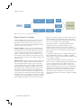
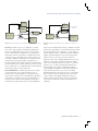
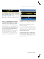
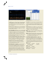
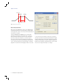
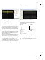
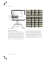
photo
Selecting an RF or Microwave Power
Sensor/Meter
Application Note
Introduction
Power measurements are fundamental to the development
cycle of any RF or microwave product, from ubiquitous mobile
phones to sophisticated radar systems. Not surprisingly, along
with the applications, the range of modulation and multiplexing
schemes also varies widely. This fact, combined with the
availability of new functions in power meters previously
reserved for higher-end analyzers, makes the choice of an
RF or microwave power measurement system more complex
than ever. Due to the large variance in product offerings and
specifications on manufacturer’s data sheets, a side by side
comparison is the best way to evaluate power sensors before
making a purchasing decision. This application note will
describe some of the factors to consider when purchasing a
USB power sensor.
Application Note
High Sensitivity
Path
RF In
Video BW
Filter
ADC
Sampling
Trigger
Splitter
Low Sensitivity
Path
Video BW
Filter
Processor
ADC
Figure 1. Tektronix PSM Power Sensor Multiple Path Block Diagram.
Basic Factors to Consider
Choosing a USB power sensor involves many of the same
criteria as traditional power meters and sensors. Factors
like frequency range, dynamic range, accuracy, zero and
calibration, speed of measurements, and triggering continue
to be critical to the selection process.
Frequency Range – Power sensors are available in a wide
degree of ranges that cover frequencies from several kHz
to 110 GHz. The most commonly used ranges are through
6 GHz to 20 GHz. Since power sensors are broadband
detectors, they detect all RF power at their input across the
entire frequency range. Variations in the frequency response
of the sensor are accounted for in the calibration table stored
within the sensor.
Dynamic Range – Dynamic range is the range of power over
which a sensor is capable of making useful measurements.
This range depends upon the type of sensor technology
used. Diode based sensors have the widest dynamic range
usually ranging from -60 dBm to +20 dBm or more. Their
wide dynamic range coupled with their quick response time
make diodes the preferred solution in most applications. A
diode sensor achieves a wide dynamic range by extending
the useful range of the diodes beyond their square law region
through the use of correction factors, and the use of multiple
diode paths. When using multiple paths, the method used to
switch between these paths can have an effect on linearity.
2
www.tektronix.com/rfpowermeters
Most sensors measure one path at a time and switch at some
threshold, typically around mid-range. This transition point
becomes a point of potential discontinuity or hysteresis which
can cause non-linearity or measurement delays.
Tektronix power sensors continuously digitize both paths
simultaneously and use a weighted average over the
transition point. This allows for a smooth and continuous
transition between measurement channels and makes the full
dynamic range of the sensor available all of the time without
discontinuities.
Compared to diode based sensors, thermistor-based sensors
have a limited dynamic range from -20 dBm to +10 dBm,
whereas thermocouple sensors typically have a dynamic range
from -35 dBm to +20 dBm.
The typical maximum input power value for most power
sensors is +20 to +23 dBm. Exceeding this value will damage
a sensor. Power attenuators and couplers can be used to
reduce the maximum power at the input of a power sensor,
shifting the dynamic range of the sensor. This can help reduce
the likelihood of accidental damage, but their use introduces
added reflections between sensor and attenuator. These
reflections decrease measurement accuracy and require
proper matching and more set-up time to calibrate out VSWR
mismatches.
Selecting an RF or Microwave Power Sensor/Meter
USB / GPIB / LAN
PC with
Automated
Test Software
PC with
Automated
Test Software
USB / GPIB / LAN
Sensor
USB
Power Meter &
Calibrator
Cal
RF In
RF In
Power Sensor
No zero or calibration
required
Power Sensor
Signal
Manual disconnections required
for zero and calibration
Signal Generator
Resistive Splitter
Device Under
Test
Signal Generator
Resistive Splitter
Device Under
Test
Figure 2a. Test system designed to accommodate zero and calibration of power sensor.
Figure 2b. Simplified test system using power sensor that does not require zero or
calibration.
Accuracy – Overall accuracy is a combination of several
error sources and is typically calculated by combining the
errors in a standardized way. These error sources include:
sensor to DUT mismatch, calibration factors, linearity, noise,
temperature, and zero-offset. While a complete discussion is
outside the scope of this application note, these error factors
are usually combined in an RSS fashion. Like Tektronix, most
manufacturers follow the ISO Guide to the Expression of
Uncertainty in Measurement which explains in excellent detail
how uncertainty factors combine. Overall accuracies for power
sensors range from 2 to 5% depending upon the manufacturer
and the type of detection technology used.
power sensor requires periodic zeroing or calibration, the ATE
system must be designed to accommodate these procedures.
This usually requires some combination of costly switches,
manual setup procedures, or dedicated software. Calibration
requires an external reference source and zeroing usually
requires the user to disconnect the device under test.
Zero and Calibration – Calibrating a power sensor requires
connecting the sensor to an external reference source.
Zeroing a sensor usually requires disconnecting the sensor
from the device under test. Zero and calibration requirements
are important considerations since these requirements can
increase test times and incremental expense, especially in
automated test systems where every second is valuable. If a
Tektronix sensors have completely eliminated user zero and
calibration. This provides excellent measurement stability
and accuracy, reduced test times, less wear on connectors,
and lower cost of software and switching hardware. The
Tektronix PSM sensors employ a patented technique to
ensure stability and calibration over the entire temperature
range, which makes them more accurate over varying
ambient temperatures than any other sensor on the market.
Most other power sensors require zeroing, at least under
certain conditions, like ambient temperature changes or
when measuring low-level signals. Check the instrument's
user manual to confirm the conditions that require zero or
calibration.
www.tektronix.com/rfpowermeters
3
Application Note
Speed of Measurements – Power sensors typically specify
several parameters that relate to measurement speed and
the vocabulary used varies between manufacturers. Some
typical terms you will see on datasheets include, "sample
rate", "reading rate", and "measurement rate". Sample rate
is the rate at which analog to digital conversion takes place.
Reading rate tells how fast the meter can convert raw samples
into measurements. These are important specifications,
but the fundamental question is, "How fast can I get settled
measurements?" The sample rate of a sensor helps determine
a sensor’s ability to measure pulse characteristics, but a
high sample rate does not directly translate into fast, settled
measurements. Reading rate has a more direct impact on
measurement speed, but it may not accurately reflect the rate
at which an instrument delivers settled power measurements.
Settled measurements not only depend on sampling rate, but
also on signal noise, signal amplitude, sensor architecture,
and the integration time required for a stable measurement.
For example, Tektronix power sensors have a real-time sample
rate of 500 kilosamples/second, and a reading rate of around
2000 readings/second. Tektronix PSM3000 sensors can make
a settled measurement, even at -40 dBm, in approximately
one millisecond. The PSM4000 and PSM5000 sensors can
take settled measurements at the low end of their dynamic
range in approximately 250 µs. The typical settling time for a
classic sensor at the same power levels is generally between
one to four seconds. When evaluating power sensors for
measurement speed, it is best to evaluate the units side by
side, rather than relying solely on datasheets.
Triggering – For most basic power measurements, triggering
is not a critical capability. However, if you need to take
measurements on a specific portion of a pulsed signal, or are
fighting to reduce test time in high-throughput ATE systems,
triggering can be an important consideration.
Basic power sensor triggering usually consists of an external
TTL input. This can be useful for synchronizing power
measurements with other instruments like signal generators,
network analyzers, oscilloscopes, or additional power sensors.
In automated test applications, the ability to externally
synchronize measurements can be critical to reducing test
times and maximizing throughput. Tektronix sensors include
both a trigger input and a trigger output to optimize test
speeds. The trigger output can tell you when the sensor is
performing a measurement and communicate that information
to other instruments down the line.
4
www.tektronix.com/rfpowermeters
Figure 3. Continuous Wave (CW) signal with constant amplitude and frequency.
More advanced power level triggering is also available in newer
sensors. These sensors can synchronize measurements with
respect to the incoming RF signals. This type of triggering is
important when measuring pulsed signals and taking burst
measurements. We will discuss this further in the Burst
Measurement and Pulse Profiling section of this application
note.
Measurement Capabilities
Choosing the right power sensor for your application obviously
depends on the signal characteristics you need to measure.
But to some extent, what you can cost-effectively measure
may also guide your test strategy. Measurement capabilities
of sensors range from basic average power measurements to
detailed pulse characteristics you would expect from a vector
signal analyzer or dedicated pulse analyzer, but might not
expect to see from a power sensor.
Average Power Measurements
Most power meters are capable of delivering accurate
average power measurements on continuous wave (CW)
signals. These common signals are of constant amplitude and
frequency. They are relatively uncomplicated and the capability
of performing average power measurements is common
to most USB power sensors. Figure 3 shows an example
of a CW signal. All Tektronix sensors have the capability of
accurately measuring average power. Though all USB power
sensors are capable of measuring average power, there is a
subset whose average power measurements are referred to as
“true average” or ”true RMS”.
Selecting an RF or Microwave Power Sensor/Meter
Figure 4. Tektronix power meter application showing a True Average (CW) measurement.
What is a True Average power measurement?
A true average power measurement gives the total power
that is incident to the sensor regardless of the modulation
bandwidth of the input signal. True average measurements
can be made using a sensor with a thermal detection unit or
by using a diode detector in its square law region. Thermal
sensors produce a true average measurement based on the
heat generated by RF energy. A true average diode detector
includes capacitance that integrates the energy received
by the detector, resulting in a measurement that closely
approximates one from the thermal sensor.
Since Tektronix PSM3000 sensors are true average sensors,
they are well-suited for measurements on broadband
modulated signals and can measure all RF energy that is
incident on the sensor input, whether that power is pulsed,
CW, AM/FM, or in a complex modulated format.
Figure 5. Time and frequency domain screen image of Tektronix RSA6100A with
stepped pulse train.
Measurements on Pulsed RF and
Microwave Signals
Choosing a sensor for analyzing pulsed signals presents a
broader set of alternatives and some additional considerations.
Pulsed signals are prevalent in RF applications such as radar,
and digital communication formats utilizing time multiplexing.
Pulse Power Measurements
When working with pulsed signals, the average power of the
overall signal may still be of interest, but the characteristics
of the pulses become more important. Understanding the
average and peak power contained within pulses is a critical
part of characterizing power amplifiers and other signal path
elements in pulsed systems.
www.tektronix.com/rfpowermeters
5
Application Note
Figure 6. Data Logger screen image within Tektronix Power Meter Application.
Figure 7. High Speed Data Logger screen image showing sample
log of multiple data points.
USB Sensors Offer New Advantages
Today’s USB-based power measurement systems have
some important advantages over the traditional meter and
sensor configuration.
Performance – The high transfer rate available in USB 2.0
and the processing power of widely-available PCs ensure
that the performance of these compact power sensor units
meets or surpasses the performance of traditional power
meters.
Low Cost – Because USB sensors are connected directly to
a PC, no base unit is required. This saves money and since
a single computer can be used for multiple sensors, USB
sensors are very economical.
Data Collection – Because USB sensors interface directly
to PCs, data collection on the PC is seamless. Tektronix
USB power sensors offer two distinct types of data logging
capabilities, each with a different purpose:
Size and Portability – USB power sensors provide flexibility
due to their lightweight and compact size. They can be used
in applications in which classic power meters are unsuited
or cumbersome. Multiple sensors can be embedded in
automated test systems or deployed in remote locations. In
the lab,their small size takes up less rack and bench space.
Data Logger – This function within the Tektronix Power
Meter application allows the user to track readings from
the virtual front panel over time.
Test System Integration – USB power sensors connect
to the PC with readily available cables and hubs. Common
Microsoft programming environments are typically supported
through dedicated API's or USBTMC. Tektronix sensors
may be controlled through a Windows API which supports
the following languages: C++, C#, LabView, and VB.net.
All Tektronix sensors include sample code, drivers, a
programmer’s manual, and code generators designed
to exercise discrete functions and allow programmers to
become familiar with the various calls.
Familiar Windows User Interface – A software interface
is an essential part of any USB-based power meter. For
customers new to USB power meters, it is important that
the software be user-friendly and easy to understand.
Tektronix power meters include an easy to use software
suite whose intuitive interface is designed to simulate a
traditional bench meter to make the transition to a USBbased system as easy as possible. Familiar toolbars and
drop-down menus allow most users to get up and running
quickly.
6
www.tektronix.com/rfpowermeters
High Speed Data Logger – Tektronix offers this function
as a separate software application. This application allows
you to rapidly collect raw data points to be post-processed later with software analysis tools.
Compatibility with Other Instruments – USB power
sensors can be integrated with other test devices that
have built-in computing power such as signal generators,
spectrum analyzers, and oscilloscopes. This eliminates the
need for a separate PC, reducing cost and saving space on
your lab bench. Tektronix PSM Series power sensors are
currently compatible with the following Tektronix products:
Oscilloscopes
-MSO5000 -DPO5000
-DPO/DSA/MSO7000
Spectrum Analyzers
-RSA5000
-RSA6000
Arbitrary Waveform Generators
-AWG5000 -AWG7000
- DPO7000
- DSA8300
Selecting an RF or Microwave Power Sensor/Meter
Duty Cycle Correction Method
One approach to measuring pulse power is to assume a
constant duty cycle value and a square pulse envelope.
For square pulses (with minimal overshoot, steep rise and
fall times), and well-defined duty cycle, pulse power can be
calculated by dividing the average power by the duty cycle.
This method is simple, may be used with low cost average
power sensors, and will give good results as long as the
duty cycle is known and the pulses are square. All Tektronix
sensors include a facility for specifying duty cycle in software.
This allows the software to calculate the pulse power, based
on the known duty cycle. This is the only way to measure
pulse power on the PSM3000 True Average series and other
average-only power sensors. However, this method introduces
error when the duty cycle is not constant and the pulse
amplitude and shape is variable.
Direct Pulse Measurement Methods
The PSM4000 and PSM5000 can measure pulse power
directly, not as a calculated measurement like the duty cycle
method used with CW sensors. Pulse power measurements
are performed within the sensors, using signal processing on
the sampled power data. Directly measuring pulse power,
instead of basing the measurement on an assumed duty
cycle, allows Tektronix power sensors to reduce uncertainty in
pulsed power measurements.
Peak Power Measurements
In addition to measuring the average power contained within
the pulse, peak power is also an important parameter. Peak
power is the highest power point of the signal waveform,
which in the case of a pulse, is usually the overshoot on the
rising edge, but can occur elsewhere if significant ringing
occurs. Peak power measurements are an important tool for
evaluating signals on the input of power amplifiers. Peaks
outside the amplifier's specifications will cause distortion. High
peak power levels from radar transmitters can cause out-ofband and spurious emissions that can impact other spectrum
uses.
Figure 8. Tektronix power meter application showing a Peak / Pulse power measurement.
The PSM4000 and PSM5000 use a combination of sampling
techniques and signal processing to deliver accurate peak and
pulse power measurements.
Real-time Sampling
The key to both pulse and peak power measurements lies
in the sampling used to capture the pulse data. As shown
in Figure 1, analog-to-digital converters are used to convert
the sensor detector output into digital form. The faster an
instrument samples (i.e., the higher the sample rate), the finer
the time resolution. This results in more precise measurements
overall and a better ability to capture peaks. The real-time
sample rate of all Tektronix sensors is 500 kS/s, which is
driven by the clock rate of the converters.
Since the power envelope is being sampled, the likelihood
of capturing an accurate peak improves with longer records.
Thus, the measurement time must be long enough to capture
a few cycles of modulation. On Tektronix meters this is
done by adjusting the number of averages, which extends
measurement time. As averaging is increased, the sensor can
make more reliable and accurate calculations of pulse power,
crest-factor, and duty-cycle.
www.tektronix.com/rfpowermeters
7
Application Note
Trigger Point
Begin Burst
Time-Slot
Delay
Time
End Burst
Time-Slot
Sweep Time
Figure 9. Diagram of a burst time slot.
Burst Measurements
Burst signals, like GSM/Edge as well as other TDMA signals,
are pulsed RF waveforms characterized by long pulse widths
and long periods. In many cases, the power in a particular part
of the burst is of interest.
Tektronix PSM4000 and PSM5000 sensors provide timegated burst measurements by allowing users to specify a
burst measurement window. The user creates this window
by setting a delay and sweep time, as shown in Figure 9.
The sensors then measure the average power, peak power,
and minimum power within the specified gate. With Tektronix
sensors, burst measurements may be internally or externally
triggered. The automatic internal trigger provides an easy way
8
www.tektronix.com/rfpowermeters
Figure 10. Tektronix power meter application Burst Measurement window.
to synchronize the measurement. When the auto trigger is
selected, the instrument automatically determines the trigger
level by sampling the incoming signal, examining the data for
maximums and minimums, and then setting the trigger level
between these maximum and minimum points. As the signal
varies, the auto trigger level adjusts accordingly.
Selecting an RF or Microwave Power Sensor/Meter
Figure 11. Tektronix Pulse Profiling application showing pulsed signal with 13 different
pulse characterization measurements.
Characterizing RF and Microwave Pulses —
Pulse Profiling
In applications like commercial cellular transmission analysis
or pulsed radar, a more detailed view of the modulation
envelope may be of value. Not only are the pulse average and
peak power needed, but measurements such as overshoot,
rise-time and fall-time are important as well. Visualization of
the modulation envelope allows for better qualitative analysis
of the signal. The Tektronix PSM5000 Series uses equivalenttime sampling to provide a 20.8 ns resolution time-domain
view of the pulse envelope without requiring a sophisticated
analyzer (see Equivalent-time Sampling, page 10). This pulse
profiling capability is rare among USB power sensors and
distinguishes Tektronix sensors.
In electronic communications, bandwidth is the width of the
range of frequencies that a signal uses. It is the difference
between the highest-frequency signal component and the
lowest-frequency signal component. Similarly, the ability of a
pulse profiling system to measure the frequencies contained
in a signal's modulation envelope is referred to as video
bandwidth. Higher video bandwidth means that a system can
measure higher frequency components and therefore faster
rise and fall times. The video bandwidth on the Tektronix
PSM5000 Series is 10 MHz.
Figure 12. Tektronix Pulse Profiling application CCDF display screen.
Tektronix PSM5000 series sensors come with a Pulse
Profiling application (shown in Figure 11) that provides 13
measurements including:
Rise Time
Fall Time
Pulse Width
Pulse Repetition Time
Pulse Repetition Frequency
Duty Cycle
Pulse Power
Peak Power
Average Power
Crest Factor
Overshoot
Droop
On/Off ratio
The Tektronix Pulse Profiling application can also provide
statistical signal analysis:
Probability Distribution Function (PDF)
Cumulative Distribution Function (CDF)
Complementary Cumulative Distribution Function (CCDF)
These statistical tools give a probabilistic view of power levels
that occur within a signal.
www.tektronix.com/rfpowermeters
9
Application Note
Multiple, Triggered Acquisitions
Sample Points
1st Cycle
}
2nd Cycle
3rd Cycle
Sampling Clocks
Feature
PSM3000 Series
PSM4000 Series
PSM5000 Series
Frequency Range
10 MHz to
26.5 GHz
10 MHz to
20 GHz
50 MHz to
20 GHz
Dynamic Range
-55 dBM to
+20 dBm
-60 dBM to
+20 dBm
-60 dBM to
+20 dBm
Measurement Speed
2000 readings/s
2000 readings/s
2000 readings/s
X
X
X
X
X
X
X
X
Measurements
True Average Power
Average (CW) Power
Duty Cycle Corrected
Pulse Power
nth Cycle
X
X
Peak Power, Pulse
Power, Duty Cycle
Measurement Logging
Composite Record
from
Multiple Acquisitions
X
Pulse Width, Rise/Fall,
Overshoot, Droop
X
Time Gated
Measurements
X
Pulse Waveform
Display with Markers
X
Table 1. Tektronix PSM Series USB Power Sensors.
Figure 13. Equivalent-time sampling.
Equivalent-time Sampling
When visually representing a signal’s envelope, the faster
the meter’s sample rate, the more accurately it can display a
signal’s characteristics. For repetitive pulsed signals, a sensor
can use equivalent-time sampling to effectively sample at a
much faster rate, enabling it to recreate a signal envelope
with greater fidelity. Equivalent-time sampling is a technique
in which a representative waveform is created with a series of
samples taken from identical repetitive waveforms. It allows
the sensor to accurately capture signals whose frequency
10
www.tektronix.com/rfpowermeters
components are higher than the sensor’s real-time sample
rate; however, the signal must be repetitive. When using
the Pulse Profiling software, Tektronix PSM5000 series
sensors achieve a 48 MS/s equivalent-time sampling rate by
gathering the necessary number of samples across several
triggers. The repetitive input signal generates the multiple
triggers needed for equivalent-time sampling and allows the
measurement system to gather the succession of data needed
to reconstruct the composite waveform image.
Selecting an RF or Microwave Power Sensor/Meter
Conclusion
A wide variety of RF and Microwave power measurement
options are available today. For USB-based power meters,
many of the traditional power sensor/meter specifications
still come into play. However, USB sensor/meters can help
simplify the chore of selecting a solution by eliminating the
need to commit to a particular mainframe. Thanks to the high
transfer rates available in USB 2.0 and the power available
in widely-available PCs, new features are available in these
compact instruments that have historically required specialized
analyzers.
www.tektronix.com/rfpowermeters
11
Contact Tektronix:
ASEAN / Australasia (65) 6356 3900
Austria* 00800 2255 4835
Balkans, Israel, South Africa and other ISE Countries +41 52 675 3777
Belgium* 00800 2255 4835
Brazil +55 (11) 3759 7627
Canada 1 (800) 833-9200
Central East Europe and the Baltics +41 52 675 3777
Central Europe & Greece +41 52 675 3777
Denmark +45 80 88 1401
Finland +41 52 675 3777
France* 00800 2255 4835
Germany* 00800 2255 4835
Hong Kong 400-820-5835
India 000-800-650-1835
Italy* 00800 2255 4835
Japan 81 (3) 6714-3010
Luxembourg +41 52 675 3777
Mexico, Central/South America & Caribbean 52 (55) 56 04 50 90
Middle East, Asia and North Africa +41 52 675 3777
The Netherlands* 00800 2255 4835
Norway 800 16098
People’s Republic of China 400-820-5835
Poland +41 52 675 3777
Portugal 80 08 12370
Republic of Korea 001-800-8255-2835
Russia & CIS +7 (495) 7484900
South Africa +27 11 206 8360
Spain* 00800 2255 4835
Sweden* 00800 2255 4835
Switzerland* 00800 2255 4835
Taiwan 886 (2) 2722-9622
United Kingdom & Ireland* 00800 2255 4835
USA 1 (800) 833-9200
* If the European phone number above is not accessible,
please call +41 52 675 3777
Contact List Updated 10 February 2011
For Further Information
Tektronix maintains a comprehensive, constantly expanding collection of
application notes, technical briefs and other resources to help engineers
working on the cutting edge of technology. Please visit www.tektronix.com
Copyright © 2011, Tektronix. All rights reserved. Tektronix products are
covered by U.S. and foreign patents, issued and pending. Information in this
publication supersedes that in all previously published material. Specification
and price change privileges reserved. TEKTRONIX and TEK are registered
trademarks of Tektronix, Inc. All other trade names referenced are the service
marks, trademarks or registered trademarks of their respective companies.
11/11
EA/FCA-POD
3GW-27136-0