1
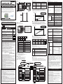
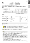
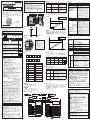
使用上の注意(続き)
形 K7L-UP-FLK
漏液位置検出器
取扱説明書
オムロン製品をお買い上げいただきありがとう
ございます。この製品を安全に正しく使用して
いただくために、お使いになる前にこの取扱説
明書をよくお読みになり、十分にご理解のうえ、
正しくご使用ください。
この製品は電気の知識を有する専門家が扱って
ください。お読みになった後も、いつも手元に
おいてご使用ください。
7. 電源投入から15分以上ウォームアップしてください 。
8. 余った検知ケーブルは折り曲げたり、きつく束ねた
りしないでください。
9. マニュアルを理解して、機器の設定をしてください。
検知ケーブルを短絡させる場合は市販の金属ブラシ
を45秒以上押しつけてください。
10. 本製品は液体の電気抵抗の変化を検出しております。
検出する液体の種類によっては、本取扱説明書に記
載の性能を満足できない場合があります。ご購入に
あたりましては必ず事前にテストを実施しご確認を
お願いいたします。
■ 外形寸法図
70
60
■ 定格
■ 異常表示
本体表示
異 常 内 容
処 置
EEPROMエラー 内部の不揮発生メモリ 本体を再起動させてくださ
い。復旧しない場合は本体
が異常です。
の修理が必要です。
ハイセンエラー
配線距離が異常です。 配線の見直しが必要です。
RTCエラー
内部の時計ICが異常 本体を再起動させてくださ
い。復旧しない場合は本体
です。
の修理が必要です。
AC100∼240V 50 / 60Hz
AC 85∼264V
消費電力
10VA 以下
動作抵抗
50kΩ、100kΩ
(感度設定により変更可能)
漏液位置精度 ※
(周囲温度 25℃)
可能配線長
表示値
計測配線長
45
シフト後の配線長
復帰抵抗
350kΩ以上で復帰
応答時間 (動作・復帰)
45秒以内
リレー出力
1 a 接点×2出力
AC250V / DC30V 3A (抵抗負荷)
機械的寿命:2000万回
電気的寿命: 8万回 リニア出力
4∼20mA DC (負荷抵抗500Ω以下)
±1%FS
通信
RSー485通信
Ym
YーXm
出力
9061032-0 D
C All Rights Reserved.
Xm
■ 取付け穴寸法図
ご使用の注意事項など詳細につきましては、必ず「形K7LUP-FLK 漏液位置検出器 ユーザーズマニュアル」(カタログ
番号:SGTE-712)をお読みください。なお、ユーザーズマニュ
アルは以下のサイトからダウンロードできます。
http://www.fa.omron.co.jp
60
0m
○
■ 補正機能
検知ケーブルの配線長を任意に変更する機能です。
実際の配線長計測値に差異が発生した場合に任意の
値に補正できます。
※ 補正を行う場合は必ずゼロシフト設定を先に行っ
てください。
80
安全上のご注意
● 警告表示の意味
注意
正しい取り扱いをしなければ、この危険
のために時に軽傷・中程度の障害を負っ
たり、あるいは物的損害を受ける恐れが
あります。
● 警告表示
○
■ 各部名称・端子構成
4
3
稀に感電や軽度のけが、発火、機器の故
障が起こる恐れがあります。分解したり、
修理、改造はしないでください。
安全上の要点
1. 下記の環境では使用・保管(輸送含む)しないで
ください。
・直射日光があたるところ
・屋外または風雨にさらされるところ
・仕様をこえる温湿度のところ
・結露のおきやすいところ
・温湿度変化の激しいところ
・振動、衝撃の影響の大きいところ
・本体に水がかかるところ、被油、塩水のあるところ
・腐食性ガス(特に硫酸ガス、アンモニアガスなど)
のあるところ
・過度の塵埃があるところ
2. DINレール取付けの場合、DINレールは、ネジで
緩みがないように取りつけてください。また、DIN
レールと本体との取りつけも確実に行ってくださ
い。緩みがあると、振動・衝撃等でDINレール、
製品本体、配線が外れる原因となります。
3. DINレールは35mm幅を使用してください。
(オムロン製 形 PFP-50N / - 100N)
4. 表面取付けする場合、取りつけネジは次の規定の
トルクで締めてください。M4ネジ 1.03N・m max.
5. 通電する前に、仕様と配線に間違いがないことを
確認してください。
6. 電源電圧および負荷は、仕様、定格の範囲内でご
使用ください。
7. 配線用圧着端子は下記のものをご使用ください。
フェニックスコンタクト製 :
接続ケーブル : AI 0.25-6BU その他
: AI 0.34-8TQ (AWG22)
: AI 0.5-8WH (AWG20)
: AI 0.75-8GY (AWG18) 8. ケーブルをもってひっぱったりしないでください。
9. 使用前に、動作テストを実施してください。
10. 作業者がすぐ電源をOFFできるよう、IEC60947-1
およびIEC60947-3の該当要求事項に適合したスイ
ッチまたはサーキットブレーカを設置し、適切に
表示してください。
11. 静電気や電界の影響を受けるところでのご使用は
避けてください。
12. 強い高周波を発生する機器やサージを発生する機
器から、できるだけ離して設置してください。
13. 誘導ノイズを防止する為に、本体への配線は、高
電圧、大電流の動力線とは分離して配線してくだ
さい。また、動力線との平行配線や同一配線を避
けてください。配管やダクトを別にする、シール
ド線を使用するなどの方法も効果があります。
14. 製品の中に金属、導線または取りつけ加工中の切
粉などが入らないようにしてください。
15. 発熱機器(コイル、巻線を有する機器等)と近接
して取付けないでください。
16. 使用しない端子には何も接続しないでください。
17. 接続ケーブル・中継ケーブル・検知ケーブル・エ
リアセパレータ・ターミネータのコネクタはきつ
く閉めるようにしてください。
18. 清掃時にシンナー類を使用しないでください。市
販のアルコールを使用してください。
19. 廃棄する場合は産業廃棄物として処理してください。
20. 接地された金属に触れるなどして、人体の静電気
を放電させてからユニットに触れてください。
使用上の注意
1. 漏液検知には当社検知ケーブル・接続ケーブル・
中継ケーブル・エリアセパレータおよびターミネ
ータをご使用ください。
2. 漏液検出後は検知ケーブルを拭きとってください。
拭いても劣化している場合は、検知ケーブルを交
換してください。
3. 検知ケーブル・接続ケーブル・中継ケーブル・エ
リアセパレータ・ターミネータに振動、衝撃を与
えないでください。
4. 人が通る場所へ敷設する場合は、保護ダクトを設
けてください。
5. 検知ケーブルのコネクタ部・接続ケーブル・中継
ケーブル・エリアセパレータ・ターミネータは漏
液検知場所から避けて設置してください。薬液が
付着した場合は交換してください。
6. 検知ケーブルを設置する際、金属のエッジに押し
つけないでください。
表示値
5
計測配線長
補正後の配線長
1
① 液晶表示部
② 操作ボタン
③ 電源端子
④ 外部リセット入力端子
⑤ 接続ケーブル端子
⑥ 警報接点出力
⑦ 漏液/断線接点出力
⑧ RSー485通信
⑨ リニア出力(4-20mA) 2
補正値
Xm
8
7
9
10 NC 12 13 NC 15 16 17
4
5
6
8
7
上 段
下 段
No.
端子名
No.
端子名
1
警報接点出力
9
電源入力
2
警報接点出力
※漏液位置精度は本体の精度です。記載している精度とは
別に検知ケーブルにも固有の誤差が発生します。
■ 性能
20MΩ以上 (DC500Vメガにて)
①と②と③の相互間
6
接続ケーブル
RSー485 A(−) 16 (抵抗線)(白) 注
○
○
1
○
○
×
○
2
×(※)
×
×
○
自動復帰
表示
ジドウ
漏液・断線が継続中の場合リセット操作で
警報出力のみ復帰可能です。
手動復帰 2 シュドウ 2 漏液・断線が解消後、リセット操作するま
で出力継続します。
漏液・断線が継続中の場合リセット操作で
警報出力のみ復帰可能です。
8 リニア出力 (−)
リセットはALT+ESCにて実行することができます。
また、外部リセット端子に短絡スイッチを接続する
ことにより外部からのリセットが可能になります。
注、接続ケーブルの色を確かめて接続してください。
■ 梱包内容
・本体 (K7L-UP-FLK)
・接続ケーブル (F03-21UP-CC)
・ターミネータ (F03-20UP-TC)
・取扱説明書
■ テスト機能
出力 (リレー、リニア) が正しく出力されているかを、模
擬入力で確認する機能です。検知ケーブルを接続せず、
出力を確認したい場合に使用することができます。テス
ト後の復帰はリセット設定に従って下さい。(デフォルト
は手動2になっています)
■ 関連商品
・検知ケーブル (F03-16UP-C-□M)
・中継ケーブル (F03-21UP-JC)
・エリアセパレータ (F03-20UP-AS)
操作説明
OKを押す
ESCを押す
プロテクトモード
日付・時刻・配線長表示
OK 3秒以上
ESC
ALT+DEL 1秒以上
監視開始
監視モード
SETTING
汚染度2、過電圧カテゴリⅡ
本質安全防爆 : [Ex ia] ⅡCT5
(株) 中村電気製作所製 防爆バリアとの組み合わせにて
UL508 CSA C22.2 No.14 (ULにて評価)
EN61010-1 (IEC61010-1)
放射妨害電界強度 CISPR11 classA
雑音端子電圧 CISPR11 classA EMI
EN61326-1 この商品は「class A」(工業環境商品)です。
(工業用途) 住宅環境でご利用されると、電波妨害の原因
EMC
静電気放電イミュニティ :EN61000-4-2
電磁界強度イミュニティ :EN61000-4-3
EMS
ファーストトランジェント/ :EN61000-4-4
EN61326-1 バーストノイズイミュニティ
(工業用途) サージイミュミティ :EN61000-4-5
伝導性妨害イミュニティ
:EN61000-4-6
電源周波数磁界イミュニティ :EN61000-4-8
電圧ディップ/電断イミュニティ:EN61000-4-11
監視停止
ご 使用に際し てのご承諾 事項
ご使用に際してのご承認事項について
下記用途に使用される場合、当社営業担当者までにご相談
のうえ仕様書などによりご確認いただくとともに定格・性
能に対し余裕を持った使い方や、万一事故があっても危険
を最小にする安全回路などの安全対策を講じてください。
a)屋外の用途、潜在的な化学的汚染あるいは電気的妨害
を被る用途またはカタログ、取扱説明書等に記載のない
条件や環境での使用
b)原子力制御設備、焼却設備、鉄道・航空・車両・設備
医用機械、娯楽機械、安全装置、および行政機関や個別
業界の規則に従う設備
c)人命や財産に危険が及びうるシステム・機械・装置
d)ガス、水道、電気の供給システムや24時間連続
運転システムなど高い信頼性が必要な設備
e)その他、上記のa)∼d)に準ずる、高度な安全性が必
要とされる用途
※上記は適合用途の条件の一部です。当社のベスト、総合
カタログ、データシート等最新のカタログ、マニュアル
に記載の保証・免責事項の内容をよく読んでご使用くだ
さい。 パラメータ
●営業にご用の方も、技術お問い合わせの方も、フリ
ーコールにお電話ください。
音声ガイダンスが流れますので、案内に従って操作
ください。
カスタマサポートセンタ クイック
オムロン
フリー
コール
設定モード
RUN
配線、感度、エリア数、
ゼロシフト、ホセイ、リレー出力、
リセット、4-20mA、
ノードNo表示
配線、感度、エリア数、
ゼロシフト、ホセイ、リレー出力、
リセット、4-20mA、 ノードNo表示
時刻設定
言語
言語(日本語、英語)
言語設定
言語設定(日本語、英語)
入力
感度、ゼロ、シフト、ホセイ、エリア
入力設定
感度、ゼロシフト、ホセイ、エリア
出力
リレー出力,リセット
出力設定
リレー出力、リセット
通信
通信プロトコル
通信設定
通信プロトコル設定
4-20mA
リニア出力
4-20mA設定
リニア出力設定
その他
バックライト、イベント,
システム情報
出力テスト
ロウエキ、ダンセン、ERR
その他
バックライト、イベント、
システム情報、初期化
※監視モードでは設定変更できません。
10∼55Hz 加速度50m/s2
X,Y,Z方向 1掃引 5分 × 10掃引
130m/s2 6方向 各3回
インダストリアルオートメーションビジネスカンパニー
営業統轄事業部 東京都品川区大崎1-11-1 ゲートシティ大崎
ウエストタワー14F(〒141-0032)
ALT+DEL 3秒以上
モニタ画面
① 電源端子一括
② リレー出力端子一括
③ ①②を除く端子一括
AC2000V 50 / 60Hz 1分間
印加箇所は絶縁抵抗と同一
設置環境
動 作
漏液・断線が解消後、自動的に復帰します。
漏液・断線が継続中の場合リセット操作を
受け付けません。
手動復帰 1 シュドウ 1 漏液・断線が解消後、自動的に復帰します。
接続ケーブル
(信号線)(黒) 注
■ パラメータ遷移図
絶縁抵抗
となる可能性があります。その場合には電波
妨害に対する適切な対策が必要となります。
○
設定
接続ケーブル
(検知線)(赤) 注
RSー485 B(+)15
時刻
2000m以下
アイコン
■ リセット機能
5
7 リニア出力 (+) 17
設定変更
0
4 漏液/断線接点出力 13 外部リセット入力
パラメータ
高度
漏液/断線/異常時の復帰は以下の方法で行うことができます。
電源入力
10
設定確認
※ リセット操作 (ALT+ESC) およびプロテクトモード移行
(ALT+DEL) のみ操作可能となります。
3 漏液/断線接点出力 12 外部リセット入力
電源投入
-25∼65℃
(但し氷結および結露のないこと)
安全規格
プロテクト
キー操作
レベル
下段
3
保存温度範囲
キープロテクトすることで、不用意な設定変更を防
止することができます。レベルの内容は以下のよう
になります。
上段
2
25∼85%RH
(但し氷結および結露のないこと)
耐衝撃
内部計測値
■ プロテクト機能
1
使用湿度範囲
耐振動
端子配列
9
-10∼55℃
(但し氷結および結露のないこと)
耐電圧
0m
6
使用温度範囲
Ym
稀に発火による物的損害が起こる恐れが
あります。端子ねじは以下のトルクで締
めてください。
推奨締め付けトルク:0.5∼0.6N・m
稀に感電や製品の破損などの物的損害が
起こる恐れがあります。ケース上面およ
び側面にあるカバーと目隠しシールは開
けないでください。
2-M4
(単位:mm)
端子構成
注 意
稀に爆発により中程度・軽度の人身障害
や物的損害が起こる恐れがあります。引
火性、爆発性ガスのあるところでは使用
しないでください。
稀に感電の恐れがあります。通電中は端
子には触れないでください。
内部計測値
総配線長 100m以下 ±1m
101∼600m ±1%
600m以下 (検知ケーブル・接続ケー
ブル・中継ケーブル・エリアセパレ
ータ、一般ケーブルの総和) 完全絶縁
処理を施した600V 0.75mm2 3芯、
ビニールキャブタイヤケーブルを使
用した場合の値 中継ケーブルは10
本以下(20m以下)
エリアセパレータは1本=10mで換算
■ ゼロシフト機能
検知ケーブルの0m位置を変更する機能です。コント
ローラと検出場所の距離がある場合、任意の距離を
0mに変更することで表示上、分かりやすくします。
56
44
90
80
電源電圧
許容電圧変動範囲
※設定モードの 部分は監視モードと異なる部分です。
0120-919-066
携帯電話・PHSなどではご利用いただけませんので、
その場合は下記電話番号へおかけください。
電話 055-982-5015(通話料がかかります)
〔技術のお問い合わせ時間〕
■営業時間:9:00∼12:00/13:00∼19:00
(土・日・祝祭日は9:00∼12:00/13:00∼17:00)
■ 営業日:年末年始を除く
上記フリーコール以外に、055-977-6389(通話料
がかかります)におかけいただくことにより、直
接FAシステム機器の技術窓口につながります。
〔営業のお問い合わせ時間〕
■ 営業時間:9:00∼12:00/13:00∼17:30
(土・日・祝祭日は休業)
■ 営業日:土・日・祝祭日/春期・夏期・年末年始
休暇を除く
●FAXによるお問い合わせは下記をご利用ください。
カスタマサポートセンタ
お客様相談室 FAX 055-982-5051
●その他のお問い合わせ先
納期・価格・修理・サンプル・仕様書は貴社のお取引先
、または貴社担当オムロン営業員にご相談ください。
70
60
Model K7L-UP-FLK
Unit Display Description of error
56
44
Countermeasure
EEPRROM ERR Error in EEPROM. Please reactivate.
It is necessary to repair
when not restoring it.
LIQUID LEAKAGE POSITION SENSOR
The wiring is
abnormal.
Error in RTC.
CABLE ERR
RTC ERR
45
80
90
INSTRUCTION MANUAL
Thank you for purchasing this OMRON product.
Read this instruction manual and thoroughly
familiarize yourself with the functions and
characteristics of the product before using it. This
product is designed for use by qualified personnel
with knowledge of electrical systems. Keep this
instruction manual for future reference.
■ Ratings
■Error Display
■ Dimensions
It is necessary to
review wiring.
Please reactivate.
It is necessary to repair
when not restoring it.
■ ZERO shift function
This is a function to change the 0 meter position
of Sensing Cable. If there is a distance between
controller and detection place, after changing the given
length to 0 meter, the display will be easy to see.
■ Mounting holes
Display value
60
Measurement
wiring length
After it changes
○
Ym
Power supply voltage
85 to 264 VAC
Power consumption
10VA max
Operate resistance
50kΩ, 100kΩ
Location accuracy *
(at 25℃)
Wiring length
Release resistance
Max 350kΩ of Operate resistance
45s max.
Xm
For detailed application procedures, refer to the Liquid
leakage position sensor K7L-UP-FLK User's Manual
(Cat.No Z287-E). It is possible to download it from
the following sites. http://www.ia.omron.com/
2-M4
Terminal composition
Indicates a potentially hazardous
situation which, if not avoided, may
result in minor or moderate injury or in
property damage.
3
4
5
● Precautionary Information
CAUTION
Please tighten by the following torques.
Doing so may occasionally result in property damage due to fire. Recommended
tightening torque : 0.5 to 0.6 N・m
Do not use the product in locations subject
to explosive and flammable gasses. Doing
so may result in injury or property damage
by a gas explosion.
Do not touch the terminals while power is
being supplied. Doing so may occasionally
result in electric shock.
Please remove neither cover nor the seal.
Doing so may result in injury or property
damage.
Do not attempt to disassemble repair, or
modify the product. Doing so may occasionally result in injury or property damage due
to electric shock, fire and failure.
Precautions for Safe Use
1. Do not use the product in the following locations.
・Locations subject to direct sunlight
・Locations subject to exposed outdoor, wind or rain
・Locations subject to outside the rated temperature and humidity ranges
・Locations where condensation may occur
・Locations subject to extreme temperature changes
・Locations subject to excessive shocks or vibration ・Locations where the product may come into contact
with water or oil or salt water
・Locations where dust or corrosive gases(in particular,
sulfuric or ammonia gas) are present
2. Fix the DIN rail so that the screws are tight.
Fix the DIN rail and the main unit firmly. It causes to
come off because of the shock and the vibration.
3. Use DIN rail with a width of 35mm.
(OMRON product : PFP-50N, /PFP-100N)
4. In case of surface mounting tighten by the following torques.
1.03N・m max.
5. Confirm the specification and wiring before it energizes.
6. Use the power supply and the load within the range of
ratings, and specifications.
7. Use the following crimp terminal for wiring.
Connecting Cable AI 0.25-6BU
Others
AI 0.34-8TQ (AWG22)
AI 0.5-8WH (AWG20)
AI 0.75-8GY (AWG18)
manufactured by Phoenix Contact.
8. Do not hold and pull the cable.
9. Confirm the operation before it uses unit.
10.Install and properly display the switch or circuit breaker
based on IEC60947-1 / IEC60947-3 standards for that
the operator could turn it off quickly.
11.Avoid use in the place where the influence of static
electricity and the electric field is received.
12.Do not install the product near devices generating strong
high -frequency waves or surge.
13.To prevent inductive noise, wiring for main unit should
be separately wired as far as possible from high voltage
or high current lines. Do not set the parallel-wiring and
same wiring with power line. Using shielded line method
is effective, too.
14.Do not allow pieces of metal, wire clippings,or fire metallic shavings of filings to enter the product.
15.Do not install near devices that generate heat.
16.Please do not connect with the terminal not used.
17.Firmly secure the connectors for Connecting Cables,
Junction Cables, Area Separators, Sensing Cables,
and Terminators.
18.Do not clean the product with paint thinner or other organic solvents.Use commercial alcohol.
19.When discarding, properly dispose of the product as
industrial waste.
20.Discharge static electricity from your body, e.g., by touching a grounded metal plate, before touching any Unit.
1
2
6
7
8
Display value
① Liquid Crystal Display
② Operation button
③ Power supply
④ External reset
⑤ Connecting Cable terminal
⑥ Alarm contact output
⑦ Liquid leakage/ disconnection contact output
⑧ RS-485 communication
⑨ Linear output (4 to 20mA)
Measurement
wiring length
After it changes
Correction
value
Xm
Terminal array
0m
Internal measurement
value
Upper
■Protection function
This is a function to prevent the improperly
setting change by key protection.
Please see the following about protection level.
9 10 NC 12 13 NC 15 16 17
Lower
1
2
3
4
5
6
7
8
Setting
Set
Protecting Key
level
operation confirmation change
No. Terminal name
Alarm contact
1
output
Alarm contact
2
output
4
No. Terminal name
Power supply
9
10
Power supply
Liquid leakage/ disconn12
ection contact output
Liquid leakage/ disconn- 13
ection contact output
External reset
5
RS-485 B (+)
6
RS-485 A (−)
7
4-20mA (+)
8
4-20mA (−)
4 to 20mA DC ±1%FS
(Load 500 Ω max.)
Communication
RS-485
○
○
○
1
○
○
×
○
2
×(*)
×
×
○
Refer to the following method of reset when liquid leakage,
disconnection and error occurred.
Setting
Auto
Operation
Reset automatically if liquid leakage and disconnection
disappeared. Not accept the reset operation if liquid
leakage and disconnection is continuing.
Manual 1 Reset automatically if liquid leakage and disconnection
disappeared. Reset only alarm output by reset operation
if liquid leakage and disconnection is continuing.
Manual 2 Continuing to output until reset operates even if liquid
leakage and disconnection disappeared. Reset only
alarm output by reset operation if liquid leakage and
disconnection is continuing.
■ Contents of packing
・Controller (K7L-UP-FLK)
・Connecting Cable (F03-21UP-CC)
・Terminator (F03-20UP-TC)
・Instruction Manual
Run the reset operation with ALT + ESC.
It is possible to reset with using external short circuiting
switch if you connect short circuiting switch to external
reset terminal.
■ Related items
・Sensing Cable (F03-16UP-C-□M)
・Junction Cable (F03-21UP-JC)
・Area Separator (F03-20UP-AS)
■TEST function
This is a function to confirm whether correct
output by simulated input. It is available if you want to
check output without Sensing Cable, Refer to reset
function about reset of after test. (Default is Manual 2)
■ Parameter transition diagram
Power-on
ALT+DEL 3 sec min.
Monitor display
date, time, length of wiring
Explanation of operation
Protection Mode
Press " OK " button
Press "ESC" button
ALT+DEL 1 sec min.
ESC
Monitoring
Mode
Setting Mode
Monitoring
start
SETTING
Parameter
RUN
Wiring, sensitivity, number
of area, zero shift, correction,
4 to 20mA, node No.
Time
Language
Sensitivity, zero shift,
correction and area
Output
Relay output, reset
Communication
4 to 20mA
Monitoring
stop
Parameter
Communication protocol
Language
setting
Language setting
(Japanese / English)
input setting
Sensitivity, zero, shift,
correction and area
Output setting
Relay output, reset
Communication
setting
Communication protocol
setting
4 to 20mA
setting
Linear output setting
Output test
Liquid leakage, disconnection, ERR
Linear output
backlight, event, system
information
Wiring, sensitivity, number
of area, zero shift, correction,
4 to 20mA, node No.
Time setting
Language
(Japanese / English)
Input
-10℃ to 55℃
(with no icing or condensation)
Ambient operating
humidity
25% to 85%
(with no icing or condensation)
Storage temperature
-25℃ to 65℃
(with no icing or condensation)
Altitude
2000m max.
*Location accuracy is controller's accuracy.
There is peculiar error margin also to the Sensing Cable.
Insulation
resistance
20MΩmin (at 500VDC)
Between ①, ② and ③
① The entire power supply terminal
② The entire relay output terminal
③ The entire terminal except ① and ②
Dielectric
strength
2000VAC 50 / 60Hz 1 minute
Between ①, ② and ③
① The entire power supply terminal
② The entire relay output terminal
③ The entire terminal except① and ②
Vibration
resistance
10 to 55 Hz
Acceleration : 50m/s2
10 sweeps of 5 minutes each in X,Y,
and Z directions.
Shock
resistance
130m/s2
3 times each in 3 axes. 6 directions.
Installation
environment
Pollution Degree 2
Overvoltage categoryⅡ
Safety
standards
UL508 CSA C22.2 No.14 (evaluated by UL)
Others
* Setting can't be changed at Monitoring Mode.
*
backlight, event, system
information, initialize
is different with Monitoring Mode.
EN61010-1(IEC61010-1)
Radiated Interference Electromagnetic
Field Strength
: CISPR11 classA
Noise Terminal Voltage : CISPR11 classA
EMI
This is a class A product. In residential
EN61326-1 areas it may cause radio interference,
in which case the user may be required
to take adequate measures to reduce
interference.
■Reset function
External reset
*Please check color of the cable.
Others
Linear
output
Ambient operating
temperature
*Only reset operation (ALT+ESC) and protection mode moving
(ALT+DEL) is available.
Cable
15 Connecting
Detection
(Red)*
Cable
16 Connecting
Resistance (White)*
Cable
17 Connecting
Signal
(Black) *
OK 3 sec min.
Icon
0
Upper
Lower
3
250VAC / 30VDC 3A
mechanical life : 20 million times
electrical life : 80,000 times
■ Characteristics
Ym
9
Safety precautions
1. The sensor must be used Sensing Cable, Connecting
Cable, Junction Cable, Area Separators and Terminator.
2. Wipe the sensor after detection. Exchange sensor if it
eroded.
3. Do not subject Sensing Cables, Connecting Cables,
Junction Cables, Area Separators, or Terminators to
vibration or shock.
4. Use the protection duct when setting it up in the place
that the person passes.
5. Do not install the connectors on the Sensing Cables or
the Connecting Cables, Junction Cables, Area Separators, or Terminators in the areas where leaks are being
detected. If chemical solution adheres to any of these,
replace them.
6. Do not press it against the edge of the metal when you
install Sensing Cable.
7. Warm up for 15 minutes min.
8. Do not fold and bundle tightly the leftover Sensing Cable.
9. Understand and set the manual. Use a metallic brush when
the Sensing Cable is short-circuit. Press the commercial
metallic brush for 45s min. If you want to short-circuit the
Sensing Cable.
10.This product detects changes in the electrical resistance
of liquids. The performance of the product specified in this
document may not be obtained for some types of liquids.
Always perform tests in advance before purchasing the
product to confirm applicability.
Internal measurement
value
■ Correction function
This is a function to make an arbitrarily-change
the wiring length of Sensing Cable. If the difference
occurred on measurement value for actual wiring length,
it can be corrected to given value.
*Please execute the ZERO shift setting previously.
■ Nomenclature
● Definition of Precautionary Information
CAUTION
0m
○
Safety Precautions
Relay
output
Output
ratings
C All Rights Reserved.
Wiring length
100m or less ±1m
101∼600m ±1%
600m max. (total of Sensing Cable, Connecting Cable, Junction
Cable, Area Separator and general-purpose cable) This value is
for completely insulated 600V
3-conductor VCT cable of with a
thickness of 0.75 mm2 .
No more than 10 Junction Cables
can be used (20 m max.).
Area Separators are calculated
as 10 m each.
Detection time
YーXm
80
100 to 240VAC
Operating voltage range
EMC
ESD Immunity
: EN61000-4-2
Electromagnetic Field Immunity
: EN61000-4-3
Fast transients Burst Noise Immunity
: EN61000-4-4
EMS
Surge Immunity
: EN61000-4-5
EN61326-1 Conducted Disturbance Immunity
(Industry)
: EN61000-4-6
Power Frequency Magnetic Field
Immunity
: EN61000-4-8
Voltage Dip/Interrupting Immunity
: EN61000-4-11
Suitability for Use
OMRON shall not be responsible for conformity with
any standards, codes, or regulations that apply to the
combination of the products in the customer's application or use of the product.
Take all necessary steps to determine the suitability
of the product for the systems, machines, and equipment with which it will be used.
Know and observe all prohibitions of use applicable to
this product.
NEVER USE THE PRODUCTS FOR AN APPLICATION
INVOLVING SERIOUS RISK TO LIFE OR PROPERTY
WITHOUT ENSURING THAT THE SYSTEM AS A
WHOLE HAS BEEN DESIGNED TO ADDRESS THE
RISKS. AND THAT THE OMRON PRODUCT IS
PROPERLY RATED AND INSTALLED FOR THE
INTENDED USE WITHIN THE OVERALL EQUIPMENT
OR SYSTEM.
See also Product catalog for Warranty and Limitation of
Liability.
Contact imformation
OMRON ELECTRONICS LLC.
One Commerce Drive Schaumburg, IL 60173-5302 U.S.A
Phone :1-847-843-7900
Fax :1-847-843-7787
OMRON CANADA INC.
885 Milner Avenue Scarborough, Ontario M1B 5V8, Canada
Phone :1-416-286-6465
Fax :1-416-286-6648
OMRON EUROPE B.V.
Wegalaan 67-69 2132 JD Hoofddorp The Netherlands
Phone :31-23-56-81-300 Fax :31-23-56-81-388
OMRON ELECTRONICS PTY. LTD.
71 Epping Road, North Ryde, Sydney, N.S.W 2113, Australia
Phone :61-2-9878-6377
Fax :61-2-9878-6981
OMRON ASIA-PACIFIC PTE. LTD.
No.438A Alexandra Road #05-05/08(Lobby 2), Alexandra
Technopark, Singapore 119967
Phone :65-6835-3011
Fax:65-6835-2711
OMRON CORPORATION.
Shiokoji Horikawa,Shimogyo-ku,Kyoto 600-8530 Japan
Phone :81-75-344-7109
Fax:81-75-344-7149