1
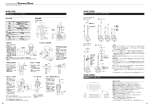
本体・操作キーの取付けについて(図
本体・操作キーの取付けについて(図 3 参照)
・本体・操作キーの取付けにはM5ねじを用い、座金を使って適正締付トルクで
電磁ロックセーフティ・ドアスイッチ
堅固に取付けてください。
Guard Lock SafetySafety-door Switch
形D4JL
D4JL-□□□□-□5N
D4JL-□□□□-□6N
取扱説明書
Instruction Sheet
Bertriebsanleitung
0686726-4 F
E
Manvel d’
d’Instrvctions
manuale d’
d’Instruzioni
manuale de Instrucciones
このたびは、オムロン製品をお買い上げいただきまして、まことにありがとうございます。
この取扱説明書では、この製品を使用する上で、必要な機能、性能、使用方法などの情報を記載しています。
この製品をご使用する際は、下記のことを守ってください。
・この製品は電気の知識を有する専門家が扱ってください。
7. About the Hinge Type Door
・この取扱説明書をよくお読みになり、十分にご理解のうえ、正しくご使用ください。
・この取扱説明書はいつでも参照できるように大切に保管ください。
Thank you for purchasing this D4JL. This INSTRUCTION MANUAL described the information such as
function, performance and how to use the product required for using the D4JL.
For using this product, please follow keep the precautions as shown in the following:
・Ensure that this product is installed and operated by qualified personal having sufficient skills in
mechanics and electrotechnic.
8. Mounting method
Original instruction
C
適
合
宣
オムロンは、形 D4JL が以下の EC 指令要求に適合していることを宣言します。
機械指令 2006/42/EC
安 全 上 の ご 注 意
●警告表示の意味
危険
正しい取扱いをしなければ、この危険のために、時に死亡に至っ
たり重傷を負う場合も起こり得ます。また、同様に深刻な物的損
害をもたらす恐れがあります。
注意
正しい取扱いをしなければ、この危険のために、時に軽傷・中程
度の傷害を負ったり、あるいは物的損害を受ける恐れがありま
す。
●警告表示
危 険
配線ミス、設定ミス、スイッチの故障などによ
り安全機能が正常に動作せず、機械により動作
し続ける場合があるため、人身事故に至る恐れがあります。稼
動開始前には必ず安全機能が動作することを確認してくださ
い。
リリースキーをUNLOCK位置で使用すると、電磁
ロック機能が働かず機械により動作し続ける場合が
あるため、人身事故に至る恐れがあります。稼動開始
前に必ずリリースキーをLOCK位置にしてください。
また、安全回路を組んでロックの状態を確認してください。
スイッチが破損し、機械により動作し続ける場合があるため、
人身事故に至る恐れがあります。
ロック強度を超える力を加えないでください。必ず本体以外に
別のロック部材(止め金など)を設置する
か、ロック強度以上の力が加わらないように警告シールやロック
状態がわかる表示灯をつけてください。
注 意
・当社専用操作キー以外のものは使用しないでください。専用操作キー以外での
操作はスイッチの破損を招くので、装置の安全性のためにも行わないでくださ
い。
・操作キーはキー挿入口のセンタに対して±0.8mm 以内にセットしてください。
位置ズレ、傾きなどがありますと、早期摩耗、破損などの原因となります。
・操作キー取付けの際、同封の取付補助ツールをキー挿入口にセットして、位置
決め(挿入口センタ及びセットゾーン)にご利用ください。(図 4 参照)
・取付補助ツールは操作キーの位置決め後は、スイッチ本体からはずしてくださ
い。
・操作キーは指定の挿入半径で、キー挿入口に対して垂直にご使用ください。
・操作キーをスイッチ本体にセットした状態にてキー先端に過度の荷重印加、ま
たは、落下などされますと、キーが変形、または本体破損の原因となります。
・使用しない箇所の操作キー挿入口は付属のキャップヘッドを取付けてください。
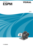
●扉の固定について
扉の固定について(図
扉の固定について(図 4 参照)
・扉を閉じているとき(操作キー挿入状態)、扉の自重、扉の緩衝用ゴム等により、
扉(操作キー)がセットゾーンを越えて押し戻されることがあります。
セットゾーン内に納まるように止め金(フック)等で扉を固定してください。
■ 配線
●回路接続例(D4JL-□
回路接続例(D4JL-□R
回路接続例(D4JL-□R□□-□□Nの場合)(図
□□-□□Nの場合)(図 5 参照)
・安全回路への入力として使用する直接開路動作接点は 表示マークで示していま
す。端子No.12-41,22-51が直接開路動作接点に相当します。
・表示灯は予備回路または端子No.E1-E2に並列に接続してご使用ください。
直接開路動作接点に並列に接続した場合、表示灯破壊時に短絡電流が流れ、設
備が誤動作する恐れがあります。
・一般負荷の開閉は、2回路以上同時に行わないでください。絶縁機能が低下する
恐れがあります。
・DC24Vソレノイドには極性があります。(E1:+極、E2:-極)端子の極性を確認
の上、配線してください。
●適用ソケット・配線
適用ソケット・配線(図
適用ソケット・配線(図 6 参照)
・配線作業時は通電しないでください。感電の恐れがあります。
・ 配線作業時にリード切りくずなど異物が本体内に入らないようにしてください。
・ 配線外れの原因となるためリード線を過大な力で引張らないでください。
・ E1/E2、O1/O2 配線時にはリード線が LED 上部にかからないようにしてくださ
い。
・適正リード線サイズはAWG22~18(0.3~0.75mm2)です。
UL、CSA認定のリード線サイズはAWG18(0.75mm2)です。
ケーブル側適用ソケット
メーカ
名称
リセ・ハウジング
AMP
リセ・コンタクト
(適用電線 AWG22~18)
機械が動作し、傷害の恐れがあります。
扉を開いた状態で操作キーを入れないでください。
稀に感電の恐れがあります。
金属コネクタ、金属配管は使用しないでください。
形式
1-1318119-4
1318105-1(連鎖状:適用工具 1385231-1)
1318107-1(バラ状:適用工具 91595-1)
● コンジット口の処理について
・ 推奨コネクタを用い、適正締付トルクで締付けてください。過大なトルクで締付
けられますとケース破損の原因となります。
・ 1/2-14NPTをご使用の際には、IP67を確保するために、コネクタのコン
安
全
上
の
要
点
ジット側にシールテープを巻付けてください。
・ ケーブルについては該当コネクタが要求する適正外径でご使用ください。
■設置環境
設置環境
・ 配線の際には、使用しない箇所のコンジット口は付属のキャップスクリューを
・ 爆発性ガス、引火性ガスなどの雰囲気中では使用しないでください。
用い、適正締付トルクで締付けてください。
・ 油中、水中での使用や常時水、油がかかる環境では使用しないでください。内部に
■ 推奨コネクタ
水や油が浸入する恐れがあります。(本スイッチの保護構造IP67とは、一定時間水
・内蔵スイッチに干渉するため、ねじ部長さが9mm以下のコネクタを使用してくださ
中に放置した後の水の浸入を確認するものです)
い。下記コネクタはねじ部長さ9mmです。
・ スイッチ本体については、埃や水などの浸入から保護されていますが、ヘッド部の
IP67確保のため、下記の推奨コネクタを使用してください。
操作キー挿入口へは異物が入らないようにしてください。早期摩耗、破損などの原
メーカ
形式
適正ケーブル外径
サイズ
因になります。
10.0~12.0mm
日 本 フ レ ッ ABS-T1612-TY
■配線
クス社製
G1/2
ABS-T1614-TY
12.0~14.0mm
・ 回路の短絡によるスイッチの破損を防ぐため、定格電流の1.5~2倍の遮断電流
LAPP ※ ST-PF1/2 5380-1002
6.0~12.0mm
値のヒューズをスイッチと直列に接続してください。
PG13.5 LAPP ※ ST-13.5 5301-5030
6.0~12.0mm
EN認定定格でご使用の場合は、IEC60269適合の10Aヒューズ 形gIあるいは形
M20
LAPP ※ ST-M20×1.5 5311-1020
7.0~13.0mm
gGをご使用ください。
・ 一般負荷(AC125V、3A)の開閉は、2回路以上同時に行わないでください。絶縁機
1/2-14NPT LAPP ※ ST-NPT1/2 5301-6030
6.0~12.0mm
能が低下する恐れがあります。
※別売のシールパッキン(形式JPK-16または、GP-13.5、または、
・ 負荷電流は定格値以下でご使用ください。
GPM20)を併用し、適正締付トルクで締付けてください。
・ 金属コネクタの使用時は、ねじ部長さが 9mm 以下のコネクタを使用してください。感
・LAPP製品 取扱い代理店:ハギテック TEL 043-423-8741
電の恐れがあります。
・1/2-14NPTは同封の変換アダプタをスイッチに取付け、 シールテープを巻
・ 金属配管は使用しないでください。コンジット口の破損によりシール不良、および感
きつけた上で上記コネクタを使用してください。
電の恐れがあります。
■ その他
・ 1/2-14NPTコネクタをご使用の場合は、金属コネクタ、金属配管を使用しないでくだ
・ 定期点検を計画的に行ってください。
さい。変換アダプタの破損によりシール不良、および感電の恐れがあります。
■ 技術仕様
・ 配線作業後は必ずカバーを取付けてご使用ください。また、カバーを開けた状態で
適合:機械指令,EN ISO14119、EN60204-1、GS-ET-19
通電しないでください。感電の恐れがあります。
認定:EN60947-5-1,IEC60947-5-1, UL508,CSA C22.2 No.14
■設置作業
設置作業
EN 電気定格
UL,CSA 電気定格
ヘッド
・ 製品を落下させないでください。スイッチ機能が十
使用カテゴリー:AC-15
DC-13
B150
Q150
分に発揮されないことがあります。
定格電圧:
AC120V
DC125V
電圧: AC120V
DC125V
・ 製品を落下させないように取付の際には十分注意
定格電流:
3A
0.55A
電流:投入 3600VA
投入 69VA
してください。けがをする恐れがあります。
遮断 360VA
遮断 69VA
・ 操作キーはドア開閉時に身体へ接触しない箇所へ取
過電圧種別:Ⅱ
付けてください。傷害の恐れがあります。
直接開路動作までの動き(最小) 15mm
・ 本体をストッパーとして使用しないでください。
直接開路動作力(最小) 60N
操作キーのツバがヘッド部に当たらないように、
ロック強度(Fzh)(最小)
:3,000N(EN ISO 14119)
図に示すように必ずストッパーを設置してください。
許容操作速度:0.05~0.5m/s
・ 本体に耐久衝撃 1000m/s2 を超える衝撃を加えない
条件付短絡電流:100A
でください。
条件:短絡保護装置:10Aヒューズ 形gI、gG(IEC60269)を使用。
■その他
その他
保護構造:IP67(EN60947-5-1) (本体のみ、操作キー挿入口は IP00)
・ 正常動作を損なう恐れがありますので、いかなる場合でも
TYPE 4X INDOOR USE ONLY (UL, CSA)
製品の分解・改造は行わないでください。
・ スイッチの耐久性は開閉条件により大きく異なります。使用にあたっては必ず実使用 最小適用負荷:DC5V,1mA,抵抗負荷(N水準参考値)
条件にて実機確認を行い、性能上問題のない開閉回数内にてご使用ください。
使用周囲温度:-10~+55℃ (ただし、氷結しないこと)
・ 保守・修理の際には設備使用者ご自身での保守・修理は行わず、設備(機械)メーカ 使用周囲湿度:95%RH以下
へご連絡(相談)ください。
機械的耐久性:100万回以上
脱出リリースボタン:3000回以上
使
用
上
の
注
意
電気的耐久性:50万回以上 (AC125V, 3A,抵抗負荷時)
■ 使用環境について
ソレノイド: 定格動作電圧:DC24V+10%/-15% 消費電流:約 200mA
・ このスイッチは屋内仕様です。
表示灯(LED): 定格電圧:DC24V
消費電流:約 8mA(緑),約 1mA(橙)
屋外で使用した場合、スイッチ故障の原因となります。
コード化レベル
:低
・ 悪性ガス(H2S、SO2、NH3、HNO3、Cl2 など)や高温高湿の雰囲気は接点接触不良
・接点ON/OFF動作には同時性はありません。ご使用条件にてご確認ください。
や腐食による破損などを生じる原因となるので使用しないでください。
・スイッチの接点は一般負荷と微小負荷共用ですが、一度負荷を開閉した接点に、
・ 下記の環境では使用しないでください。
さらに容量の小さい負荷を接続して使用することはできません。接点表面が荒れ
・ 温度変化の激しい場所
て、接触信頼性が損なわれる恐れがあります。
・ 湿度が高く、結露が生じる恐れのある場所
・ 振動の激しい場所
ご承諾事項
・ 防護扉内側での切粉、加工屑、油、薬品のかかる場所
・ 洗剤・シンナーなどの溶剤がかかる場所
「当社商品」は、
一般工業製品向けの汎用品として設計製造されています。
従いまして、
■ スイッチの保管について
次に掲げる用途での使用は意図しておらず、お客様が「当社商品」をこれらの用途に使
・スイッチを保管する場合は、悪性ガス(H2S、SO2、NH3、HNO3、Cl2 など)や塵埃、
用される際には、「当社」は「当社商品」に対して一切保証をいたしません。ただし、次
高温高湿を避けてください。
に掲げる用途であっても「当社」の意図した商品用途の場合や特別の合意がある場合
■ ソレノイドロックタイプについて
は除きます。
・ソレノイドロックタイプは、ソレノイド通電時しかロックがかかりませんので、急な停
(a) 高い安全性が必要とされる用途(例:原子力制御設備、燃焼設備、航空・宇宙設
電などにより、ソレノイドへの通電がなくなると、ロックが解除となります。従って
備、鉄道設備、昇降設備、娯楽設備、医用機器、安全装置、その他生命・身体に危険
機械停止後も扉内部が危険状態を維持するような機械にはソレノイドロックタイ
が及びうる用途)
プは使用しないでください。
(b) 高い信頼性が必要な用途(例:ガス・水道・電気等の供給システム、24 時間連
■リリースキーについて(
リリースキーについて(図
リリースキーについて(図 1 参照)
続運転システム、決済システムほか権利・財産を取扱う用途など)
・停電時あるいは緊急時にロックを解除する場合に用います。
(c)
厳しい条件または環境での用途(例:屋外に設置する設備、化学的
・同封の専用ツール(特殊リリースキー)を用いて、LOCK 位置から UNLOCK 位置に
汚染を被る設備、電磁的妨害を被る設備、振動・衝撃を受ける設備など)
するとロックが解除して安全扉などを開けることができます。(メカニカルロックタイ
(d)
「カタログ等」に記載のない条件や環境での用途
プのみ)
*(a)から(d)に記載されている他、「本カタログ等記載の商品」は自動車
・保守などで UNLOCK 位置に変更した後は、ご使用前に必ず LOCK 位置にしてく
(二輪車含む。
以下同じ)向けではありません。自動車に搭載する用途には利用しな
ださい。
いで下さい。自動車搭載用商品については当社営業担当者にご相談ください。
・出荷時のリリースキー設定位置は、D4JL-□□□A は UNLOCK 位置、D4J
*上記は適合用途の条件の一部です。
当社のベスト、総合カタログ、データシートなど
L-□□□G は LOCK 位置となっています。
最新版のカタログ、マニュアルに記載の保証・免責事項の内容をよく読んでご使用くだ
・UNLOCK 位置の状態では、大型マシン・踏み込み型マシンなど内での予備調整
さい。
作業中に扉が閉じても、ロックがかからずマシンも起動しません。
・このリリースキーを、マシンの停止始動用に使用しないでください。
オムロン株式会社
・リリースキーによる補助ロック解除は責任者のみが行ってください。
インダストリアルオートメーションビジネスカンパニー
・リリースキーのねじ部に過度(1N・m以上)の力を加えないでください。
リリースキーが破損し、操作できなくなる恐れがあります。
●お問い合わせ先
・不特定な人による容易なリリースキーによるロック解除を避けるため、リリース
カスタマサポートセンタ
キーは LOCK 状態にして、シールワックス(ろう付け)などを施し、封印してく
ださい。リリースキーの操作後は、スイッチの操作を再開する前に、その封印を
復旧してください。
(フリーコール)
■脱出
脱出リリース
脱出リリースボタンについて(図
リリースボタンについて(図 2 参照)
携帯電話・PHS などではご利用いただけませんので、
・作業者が作業エリア(危険エリア内)で第三者に扉をロックされて閉じ込められた
その場合は下記電話番号へおかけください。
場合の緊急脱出に用います。
・脱出リリースボタンを押すと扉のロックが解除されます。
電話 055
055982-982
-5015 (通話料がかかります)
・脱出リリースボタンの使用後は、ボタンを引き出し、元の状態に戻してください。
【技術のお問い合わせ時間】
ボタンが押し込まれた状態では、扉が閉じても、ロックがかからずマシンも起動し
■営業時間:8:00~21:00
■営業日:365 日
ません。
・脱出リリースボタンは作業者が作業エリア(危険エリア内)から操作できるよう設
■上記フリーコール以外の FA システム機器の技術窓口:
置してください。
電話 055055-977977-6389 (通話料がかかります)
■カバーの取付について
カバーの取付について
・カバーを閉める際には、リリースキーを LOCK 位置にしてください。
【営業のお問い合わせ時間】
・シールゴムのズレや浮き、及び異物の付着があるとシール性を損ないます。異常
■営業時間:9:00~12:00/13:00~17:30 (土・日・祝祭日は休業)
のないことを確認し使用してください。
■営業日:土・日・祝祭日/春期・夏期・年末年始休暇を除く
・正規のねじ以外は使用しないでください。シール性が低下する恐れがあります。
●FAX によるお問い合わせは下記をご利用ください。
■ヒンジ形開閉扉について
ヒンジ形開閉扉について
カスタマサポートセンタ お客様相談室 FAX 055-982-5051
・ヒンジに近い位置に取付けると、製品本体のロック部に操作した力以上荷重が印加
され、ロック機能の破損の原因となります。取手に近い位置に取付けてください。
■ 取付方法
●その他のお問い合わせ先
● 適正締付トルク
納期・価格・修理・サンプル・仕様書は貴社のお取引先、
・ねじのゆるみは早期故障の原因となりますので、各部の適正締付トルクにて
または貴社担当オムロン営業員にご相談ください。
締付けてください。
0120120-919919-066
端子ねじ
カバー取付けねじ
操作キー取付けねじ
本体取付けねじ
コネクタ
キャップスクリュー
0.6~0.8N・m
0.7~0.9N・m
2.4~2.8N・m
3.2~3.8N・m
1.8~2.2N・m(1/2-14NPT以外)
1.4~1.8N・m(1/2-14NPT)
1.3~1.7N・m
OMRON declares that D4JL is in conformity with the requirements of the following
EC Directives:
Machinery Directive 2006/42/EC
●Definition of Precautionary Information
Indicates an imminently hazardous situation which, if not
avoided, is likely to result in serious injury or may result in death.
Additionally there may be severe property damage.
DANGER
ndicates a potentially hazardous situation which, if not avoided,
CAUTION Imay
result in minor or moderate injury or in property damage.
●Precautionary Information
DANGER
Always verify the operation of the safety functions before
starting the system.Not do so may result that the safety
functions may not be performed as expected if wiring or
settings are incorrect or the Switch have failed.The controlled
system may continue to operate and possibly resulting in
injury or death.
Always ensure that the release key is set to the "LOCK" position
before starting the system. If the release key remain set to
"UNLOCK", the electromagnetic lock function will not operate and
the system may continue to operate, possibly resulting in injury or
death.
Always monitor the solenoid NC contact (Terminal
41-42) in your safety circuit.
Do not connect indicator devices (like LED) to safety
circuit connected to terminal 41-42.
Do not apply force exceeding the specified maximum holding force.
Doing so may damage the Switch lock mechanism and the system
may continue to operate, possibly resulting in injury or death. Either
install another locking component (e.g., a stopper) in addition to the
Switch, or use a warning measures or an indicator showing the
controlled system is locked to avoid overloading the holding force
in lock mode.
CAUTION
Do not dismount the operation key from the door intentionally and
insert it to the switch with the door open. Machine may start
operating and injury or death may be caused.
Precautions for Correct Use
1. Environment
1-1. The switch is intended for indoor use only.
1-2. Do not use your D4JL outdoor, or the switch will malfunction.
1-3. Do not use your D4JL in the atmosphere of hazardous gases (H2S, SO2, NH3,
HNO3, CI2, etc.) or high temperature and humidity, or it will cause the
imperfect closing of the contacts or the breakage thereof stemming from
corrosion.
1-4. Do not use the switch under any of the conditions mentioned below.
・ Frequent temperature range.
・ High humidity or dew condensation may be generated.
・ Where the switch is subject to severe vibration.
・ Where the metal dust, oil, or chemical is sprayed inside the door.
・ Where thinner is applied.
2. Storage
Do not keep the switch in dusty, humid place and any place where gas may be
present for example H2S, SO2, NH3, HNO3, Cl2.
3. About the Solenoid Lock Type
3-1. In the solenoid lock type, a lock is closed only when the solenoids are
energized. A lock may be opened when the passage of an electric current to
the solenoids is stopped due to sudden power failure. Do not use the solenoid
lock type for the machine in which the inside of the door remains dangerous
even after shutdown of the machine.
4. Using the Release Key (See Figure 1)
4-1. The Release Key is used to open a lock in the case of power failure or
emergency.
4-2. With the supplied special-purpose tool (special release key), turn the Release
Key from the LOCK position to the UNLOCK position to release the lock.
This can open the safety door. (For the mechanical lock type only.)
4-3. When the Release Key is in the UNLOCK position during maintenance work,
return it to the LOCK position before use.
4-4. The set position of the Release Key at the shipping of the switch is as noted below;
*D4JL-□□□A :Unlock position *D4JL-□□□G :Lock position
4-5. While the Release Key is in the UNLOCK position, a lock is not closed and a
machine is not activated even when the door is closed in the course of
preliminary adjustment work performed inside a large machine or a
depressing type machine.
4-6. Do not use the Release Key when starting or stopping the machine.
4-7. The releasing of the auxiliary lock must be handled by an authorized person.
4-8. Do not apply an excessive force (of 1N・m or more) to the threaded portion of
the Release Key. The Release Key may be damaged to the extent that it no
longer becomes operational.
4-9. To prevent the release key from being used by unauthorized personnel, set it to LOCK and seal
43.5 ±0.1
参考(φ50)
Hole for Escape Release Button
44.2 ±0.1
For reference (φ50)
セットゾー
ン
3.3mm
2-M5
18.5 ±0.1
23.5 ±0.1
22±0.1
〈本体取付穴加工寸法〉
(Processing Dimensions of Main
Body Mounting Hole)
図 3 (Fig.3)
図 2 (Fig.2)
Suitability for use
Omron Companies shall not be responsible for conformity with any standards, codes or
regulations which apply to the combination of the Product in the Buyer’s application or
use of the Product. At Buyer’s request, Omron will provide applicable third party
certification documents identifying ratings and limitations of use which apply to the
Product. This information by itself is not sufficient for a complete determination of the
suitability of the Product in combination with the end product, machine, system, or other
application or use. Buyer shall be solely responsible for determining appropriateness of
the particular Product with respect to Buyer’s application, product or system. Buyer
shall take application responsibility in all cases.
NEVER USE THE PRODUCT FOR AN APPLICATION INVOLVING SERIOUS
RISK TO LIFE OR PROPERTY OR IN LARGE QUANTITIES WITHOUT
ENSURING THAT THE SYSTEM AS A WHOLE HAS BEEN DESIGNED TO
ADDRESS THE RISKS, AND THAT THE OMRON PRODUCT(S) IS PROPERLY
RATED AND INSTALLED FOR THE INTENDED USE WITHIN THE OVERALL
EQUIPMENT OR SYSTEM.
OMRON Corporation Industrial Automation Company
OMRON EUROPE B.V.
Wegalaan 67-69-2132 JD Hoofddorp The Netherlands
Tel: (31)2356-81-300 / Fax: (31)2356-81-388
OMRON ASIA PACIFIC PTE. LTD.
No. 438A Alexandra Road # 05-05/08 (Lobby 2),Alexandra Technopark, Singapore
119967
Tel: (65) 6835-3011 / Fax: (65) 6835-2711
OMRON SCIENTIFIC TECHNOLOGIES INC.
6550 Dumbarton Circle, Fremont CA 94555-3605 U.S.A.
Tel: (1) 510-608-3400 / Fax: (1) 510-744-1442
OMRON (CHINA) CO., LTD.
Room 2211, Bank of China Tower, 200 Yin Cheng Zhong Road,PuDong New Area,
Shanghai, 200120, China
Tel: (86) 21-5037-2222 / Fax: (86) 21-5037-2200
操作キー
Operating Key
ロックモニタ
スイッチ
(Lock Monitor Switch)
LED
B1 02
(-)
A4
A3
図 4 (Fig.4)
ドア開閉検知
スイッチ
(Door Open/Close Detection Switch)
42
41
図 5 (Fig.5)
51
52
61
A2
取付補助ツール
Auxiliary Mounting Tool
Traceability Information
Representative in EU
OMRON EUROPE B.V.
Wegalaan 67-69 2132 JD Hoofddorp
The Netherlands
Manufacturer
OMRON CORPORATION, Safety Device Division
Shiokoji Horikawa, Shimogyo-ku, Kyoto, 600-8530 JAPAN
E1
(+)
89 ±0.1
〈操作キー取付穴加工寸法〉
(Processing Dimensions of
Operating Key Mounting Hole)
・There is no equality between the ON/OFF motions of a contact.
・The switch contacts are common use for general load and micro load but, after
switching a general load, it is impossible to switch a micro load with the same
contacts. The contact reliability would be decrease due to the rough contact surface.
it with sealing wax. After the release key operation should be restored to its sealed before restart
E2
(-)
01
A1 (+)
1-1318119-4
1318105-1
(Chain type: Applicable tool 1385231-1)
1318107-1
(Separate type: Applicable tool 91595-1)
9-3.Conduit opening
1). Use the connectors recommended in clause 10 and tighten the connector with
specified torque in clause 8-1. An excessive torque will bring a case breakage.
Apply sealing tape between connector and conduit opening so that the
enclosure will conform to IP67. Use a cable with a suitable diameter for the
connector. For unused conduit opening, apply a conduit cap provided and
tighten it to specified torque in clause 8-1.
10. Recommendation of connector
Use the connector with thread section of 9mm long or less. In the case of the
connector with longer thread section, protruded part may interfere with the
other parts inside the body.
Use below listed connector to secure IP67.
Size
Manufacture
Type
Adequate cable
Diameter
ABS-T1612-TY
10.0 to 12.0 mm
NIPPON FLEX
G1/2
ABS-T1614-TY
12.0 to 14.0 mm
LAPP ※
ST-PF1/2
5380-1002
6.0 to 12.0 mm
PG13.5
LAPP ※
ST-13.5
5301-5030
6.0 to 12.0 mm
M20
LAPP ※
ST-M20*1.5 5311-1020
7.0 to 13.0 mm
1/2-14NPT LAPP ※
ST-NPT1/2 5301-6030
6.0 to 12.0 mm
※Use an optional seal packing (Type: JPK-16, GP-13.5, or GPM20).
Tighten the seal packing to a proper tightening torque.
・LAPP is a German manufacturer.
・Before a connector of 1/2-14NPT size is used, install a supplied
conversion adapter on the switch and wrap it in seal tape.
11. Others
11-1 Please do a regular check in premeditation for this switch
12. Technical specification
Conformity : Machine Directive , EN ISO14119, EN60204-1, GS-ET-19
Approval:EN60947-5-1,IEC60947-5-1,UL508,CSA C22.2 No.14
EN electrical rating
UL, CSA electrical rating:
Utilization category:AC-15/DC-13
B150
Q150
Rated Voltage:
120VAC / DC 125V Voltage:
AC 120V DC125V
rated Current:
3A / 0.55A
Volt Amp.: Make 3600VA
69VA
Break 360VA
69VA
Overvoltage Category : Ⅱ
Direct opening travel (min.)
15 mm
Direct opening force (min.)
60 N
Holding force (Fzh): (min.) : 3,000 N (EN ISO14119)
Adequate operating speed:0.05 to 0.5 m/s
Conditional short-circuit current : 100A
Short circuit protective device:Use 10 A fuse, type gI or gG, in accordance with
IEC 60269
Enclosure rating:IP67 (EN60947-5-1) (Operation key insertion face : IP00)
TYPE 4X INDOOR USE ONLY (UL, CSA)
Minimum permissible load:5VDC,1mA resistive load (N level : reference value)
Ambient temperature range:-10 to +55℃ (Protect against Frost)
Ambient humidity (max.):95%RH
Mechanical durability (min.):1,000,000 operations
Escape release button: 3000 times or more
Electrical durability (min.):500,000 operations (AC125V,3A resistive load)
Solenoid : Rated working voltage:DC24V+10%/-15%
Current consumption:Approximately 200 mA
Indicator lamp(LED) : Rated voltage:DC24V
Current consumption:Approx.8 mA (green) Approx. 1 mA (orange)
Level of coding:Low
5. Using the Escape Release Button (See Figure 2)
5-1. The Escape Release Button is used for emergency escape in the case where
the door is locked by a third person and workers are confined in the work area
(or the dangerous area).
5-2. Pressing the Escape Release Button will release the lock of the door.
5-3. Return the depressed Escape Release Button to its original position after use.
While the Escape Release Button is depressed, a lock is not closed and a
machine is not activated even when the door is closed.
5-4. Install the Escape Release Button to ensure that a worker can operate it from
inside the work area (or the dangerous area).
6. Installing the Cover
6-1. Turn the Release Key to the LOCK position when closing the cover.
6-2. Confirm that the seal rubber has no abnormality and then use it.
If the seal rubber is displaced or floated, or if foreign matters adhere to the
seal rubber, the seal rubber will lose its sealing capability.
6-3. Do not use any screw other than correct one, or the sealing capability of the
seal rubber will deteriorate.
7. About the Hinge Type Door
7-1. A door is mounted near a hinge, excessive load may be imposed beyond a force
acting on the lock portion of this Equipment. This may result in damage to the
lock mechanism. Mount it to a position near a handle.
0.8mm
ロック解除
Lock Release
(Applicable Electric
Wire AWG22~18)
Precautions for Safe Use
(取付補助ツール)
(Auxiliary Mounting Tool)
Rese Housing
Rese Contact
AMP
1. Environment
1-1. Do not use the switch where explosive gas, ignitable gas, or any other harmful
gasses may be present.
1-2. Do not use the switch in the oil and in the water. IP67(EN60947-5-1)
1-3. Though the switch body is protected from the ingress of dust or water, avoid the
ingress of foreign substance through the key hole on the head.
Otherwise, wear in short time or break may be caused.
2. Wiring
2-1. Connect the fuse to the switch in series to prevent it from short circuit damage.
The value of the breaking current of the fuse must be increased to cover the rated
current by 150 to 200%. When using the switch with EN rating, use 10 A fuse, type
gI or gG that complies with IEC 60269.
2-2. On the switching of general loads (250VAC/3A), do not operate two circuits or
more at the same time. Otherwise, insulation performance may be degraded.
2-3. Keep the electrical load below the rated value.
2-4.Use a metallic connector which has a threaded portion of 9 mm length or less.
2-5. Do not use metal conduit with this switch. The broken conduit hole may cause
electrical shock hazard.
2-6. Use of a 1/2-14NPT connector may result in damage to a conversion adapter,
causing defective sealing or a risk of electric shock. Do not use metallic connectors
and metallic conduit.
2-7. Be sure to install a cover after the wiring.
Do not put the electric power when opening a cover.
2-8. Do not put the electric power when wiring.
3. Mounting
3-1. Be careful not to drop your D4JL, or the switch will not fully exhibit its ability.
3-2. This may cause a risk of personal injury.
Stopper
ヘッド
Head
Extra care must be taken not to drop this
product during installation.
3-3. Install operation key so that it will not hit the operator
when the door is open. Injury may be caused.
3-4.Do not use the switch as a stopper.
Operating Key
Be sure to install a stopper as shown in the
following illustration to prevent the edge
Switch
of the operation key from inadvertently
hitting the switch directly.
2
Do not apply shock over the shock resistance 1000m/s on the switch.
4. Others
4-1. Do not disassemble or remodel your D4JL in any case, or the D4JL will not
operate normally.
4-2. The durability of the switch is seriously affected by operating conditions.
Evaluate the switch under actual working conditions before permanent
installation.
4-3. Please mention in machine manufacturer’s Instruction.
Manual that the user must not repair nor maintain the switch and must contact
machine manufacturer for them.
0.6 to 0.8 N・m
0.7 to 0.9 N・m
2.4 to 2.8 N・m
3.2 to 3.8 N・m
1.8 to 2.2 N・m
(except for 1/2-14NPT)
1.4 to 1.8 N・m (1/2-14NPT)
1.3 to 1.7 N・m
Cap screw
8-2. Switch, operation key(See Figure 3)
1) The switch and operation key will be fastened to specified torque in clause 8-1
with M5 screws and washers.
2) Do not use the operation key other than dedicated OMRON’s.
Otherwise switch may be damaged.
3) Be sure that the operation key can be inserted properly to key hole with a
tolerance of ± 0.8mm.
4) When installing the Operating Key, place the supplied auxiliary mounting
tool at the keyhole, and use it for a positioning purpose (hole center and set
zone). (See Figure 4)
5) Remove the auxiliary mounting tool from the switch after positioning the
Operating Key.
6) Insert the operation key into the key hole according to the specified “operation
key insertion radius in horizontal direction”.
7) Do not impose excessive force on the key top while the operation key is
inserted into the switch body or drop the switch with the operation key
inserted to avoid the deformation of the key or the breakage of the switch body.
8) Attach cap heads to any Operation Key holes that are not being used.
8-3. Securing of the door(See Figure 4)
1) If the operation key is pulled in the opening direction due to a force caused by
vibration, by the door weight, or by a cushion attached to the door.
The closed door must be secured with a hook or by similar means.
9. Wiring
9-1. Example of Circuit Connections (for D4JL-□R□□-□□N) (See Figure 5)
1). The open circuit operating contacts are labeled with marks. They are used as
input to the safety circuit. Terminals No. 12-41 and No. 22-51 correspond to
the direct open circuit operating contacts.
2). An indicator lamp must be connected in parallel to a preliminary circuit or
Terminal No. E1-E2. If an indicator lamp is connected in parallel to a direct
open circuit operating contact, a short-circuit current may run when the
indicator lamp is destroyed. This may cause a malfunction in the equipment.
3). Do not open or close two circuits or more under normal load. The insulation
function may decrease.
4). The DC 24V solenoid has a polarity.( E1: Positive (+) polarity, E2: Negative
(-)polarity)
9-2. Applicable Sockets and Wiring (See Figure 6)
1). Do not put the electric power when wiring
2). Do not let particles such as small piece of lead wire in the switch body when wiring.
3). Make sure that the wiring does not hide the LED when wiring E1/E2 or 01/02.
4). Do not pull on lead wires with excessive force. The wires may break.
5). Adequate conductor size is AWG 22 to 18 (0.3 to 0.75mm2).
For UL,CSA , Adequate conductor size is AWG 18 ( 0.75mm2).
Cable-side socket
Manufacture
Name
Type
Do not use metal connector or conduit with the switch. The broken
conduit hole may cause electrical shock hazard.
50 ±0.1
3-M5
Terminal screw
Cover clamping screw
Operating key clamping screw (See item 8・3)
Body clamping screw
(See item 8・3))
Conduit mounting connection
SAFETY PRECAUTION
脱出リリースボタン穴
背面リリースボタン穴
参考(φ50)
図 1 (Fig.1)
8-1. Mounting Screw Tightening Torque
Loose mounting may result in malfunction.
Fasten the screws to the specified torque.
EC Declaration of Conformity
Conformity
言
OMRON Corporation
11
→
12 B4
21
→
22 B3
31
→
32
安全回路へ
To Safety Circuit
B4 B3 B2 B1
A4 A3
A2 A1
右引出し(Right Hand):15±2mm
下引出し(Bottom Hand):60±2mm
安全回路へ
To Safety Circuit
62
B2
制御回路へ
To Control Circuit
図 6 (Fig.6)
WICHTIGE SICHERHEITSHINWEISE
Definition der Sicherheitsinformationen
VORSICHT
REGLES DE SECURITE
Una operazione non corretta può anche causare, data la
sua potenziale pericolosità, ferite leggere o di medio
grado, oppure danni al materiale.
ATTENZIONE
Une utilisation incorrecte de ce produit pourrait donner lieu
à des blessures de moindre ou moyenne gravité et à des dégâts
matériels.
Indicazione di avvertenza
Avertissements
Sicherheitsinformationen
Significado de las indicaciones de advertencia
Significato delle indicazioni di avvertenza
PRECAUTION
Weist auf eine mögliche Gefährdungssituation hin, die bei
Missachtung kleine, mittelschwere Verletzungen oder
Sachschäden hervorrufen kann.
OBSERVACIONES PARA LA SEGURIDAD
PRECAUZIONI PER LA SICUREZZA
Signification des avertissements
DANGER
PERICOLO
Überprüfen Sie stets die Funktion der Sicherheitsvorrichtungen, bevor Sie das System in Betrieb nehmen.
Wird diese Überprüfung nicht durchgeführt, besteht die Gefahr, dass die Sicherheitsvorrichtungen nicht wie
erwartet arbeiten, wenn die Verdrahtung oder Einstellungen fehlerhaft sind oder die Schalter ausgefallen
sind. Das gesteuerte System setzt dadurch seinen Betrieb möglicherweise in einer Gefahrensituation fort,
was zu Verletzungen oder zum Tod führen kann.
Achten Sie stets darauf, dass der Freigabeschlüssel in der Stellung "LOCK" steht, bevor Sie das System im
Betrieb setzen. Wenn der Freigabeschlüssel in der Stellung "UNLOCK" verbleibt, arbeitet die
elektromagnetische Verriegelungsfunktion nicht, und das System setzt seinen Betrieb möglicherweise in einer
Gefahrensituation fort, was zu Verletzungen oder zum Tod führen kann. Überwachen Sie stets den Öffner-Kontakt
der Magnetverriegelung (Klemmen 41-42) in Ihrer Sicherheitsschaltung.
Wenden Sie keine Kraft an, die die spezifizierte maximale Zuhaltekraft übersteigt. Andernfalls besteht die
Gefahr einer Beschädigung des Verriegelungsmechanismus und das System setzt seinen Betrieb möglicherweise
in einer Gefahrensituation fort, was zu Verletzungen oder zum Tod führen kann Installieren Sie entweder
eine weitere Verriegelungseinrichtung (z. B. einen Riegel) zusätzlich zum Schalter oder verwenden Sie eine
WarnmethodeoderAnzeige,durchdieabgezeigtwird,dassdasSystemgesperrtist,damitkeineKräfteangewendet
werden, die die Zuhaltekraft im verriegelten Zustand übersteigen.
Vérifiez toujours le fonctionnement des dispositifs de sécurité avant le démarrage du système. Le non-respect
de cette règle peut entraîner le fonctionnement incorrect des dispositifs de sécurité si le câblage ou les
paramètres sont incorrects ou en cas de défaillance des commutateurs. Il se peut que le système commandé
continue à fonctionner, provoquant des blessures ou la mort.
Assurez-vous en permanence que la clé de déverrouillage est en position "VERROUILLAGE" (LOCK) avant le
démarrage du système. Si la clé de déverrouillage reste en position "DÉVERROUILLAGE" (UNLOCK), la fonction
de verrouillage électromagnétique ne fonctionnera pas et il se peut que le système continue à fonctionner,
provoquant des blessures ou la mort. Contrôlez toujours le contact normalement fermé à solénoïde (borne
41-42) du circuit de sécurité.
N'appliquez pas une force supérieure à la force de maintien maximale spécifiée. Le non-respect de cette
règle peut endommager le mécanisme de verrouillage du commutateur et il se peut que le système continue
à fonctionner, provoquant des blessures ou la mort. Installez plutôt un autre système de verrouillage (par
exemple un dispositif d'arrêt) en plus du commutateur, ou utilisez une méthode ou un panneau d'avertissement
pour indiquer que le système commandé est verrouillé afin d'éviter une force de maintien trop importante
en mode de verrouillage.
Verificare sempre il funzionamento delle funzioni di sicurezza prima di avviare il sistema. In caso contrario,
le funzioni di sicurezza potrebbero non funzionare come previsto se il cablaggio o le impostazioni non sono
corrette o in presenza di un guasto del finecorsa. Il sistema controllato potrebbe quindi continuare a
funzionare ponendo in grave pericolo l'incolumità dell'operatore (rischio di lesioni o morte).
Verificare sempre che la chiave di rilascio sia in posizione di blocco (LOCK) prima di avviare il sistema.
Se la chiave di rilascio è in posizione di sblocco (UNLOCK), la funzione di blocco elettromagnetico sarà
disattivata e il sistema potrebbe continuare a funzionare ponendo in grave pericolo l'incolumità
dell'operatore (rischio di lesioni o morte). Monitorare sempre il contatto NC del solenoide (terminali 41-42)
nel circuito di sicurezza.
Non applicare una forza superiore alla forza di ritenzione massima specificata. In caso contrario, il
meccanismo di blocco delfinecorsapotrebbe danneggiarsi e il sistema potrebbe continuare a funzionare ponendo
in grave pericolo l'incolumità dell'operatore (rischio di lesioni o morte). Installare un dispositivo di
blocco aggiuntivo oltre al finecorsa, ad esempio un fermo, oppure utilizzare una spia o un messaggio di
avviso per segnalare il blocco del sistema controllato, al fine di evitare il superamento della forza di
ritenzione in modalità di blocco.
PRECAUTION
"SteckenSiedenBetätigernichtbei geöffneterTürindenSchalter.DadurchkanndieMaschineunerwartetanlaufen."
■Technische Daten
Zwangsöffnungskraft
Zwangsöffnungsweg
Geeignete Betriebsgeschwindigkeit
Max. Betriebsfrequenz
Kurzschlussschutz
Nennstoßspannung (Uimp)
Schutzartklasse
Umgebungstemperatur
Nennspannung
Verdrahtung
: AC-15 3A /120VAC / DC-13 0,55A/125VDC
NEMA B150, Q150
: min. 60N
: min. 15mm
: 0,05 bis 0,5 m/s
: 30 Zyklen/min
: 10A Sicherung, gI oder gG (IEC60269)
: 4kV(Zwischen Anschlüssen unterschiedlicher Polarität)
: IP67 (EN60947-5-1), TYPE 4X INDOOR USE ONLY (UL, CSA)
: –10℃ bis +55 ℃ (ohne Vereisung)
: Magnetspule 24VDC
Warnleuchte 24VDC
: AWG 22 bis 18 (0,3 bis 0,75 mm2)
Anzugsdrehmoment
Couple de serrage approprié
Coppia di serraggio adeguata
Par de apriete apropiado
1. Il se peut que le commutateur ne fonctionne pas pleinement. Ne faites pas tomber le produit.
2. Risque de blessure. Lors de l'installation de l'appareil, veillez à ce qu’il ne tombe pas.
3. Ne démonter ou trafiquer ce produit en aucun cas. Cela pourrait empêcher son fonctionnement normal.
4. Ne pas utiliser ce produit dans un environnement à gaz explosif, gaz inflammable etc.
12. Connecter le commutateur en série à un fusible à courant de rupture de 1,5 à 2 fois supérieur au courant nominal pour éviter
les dommages
Retenue
ヘッド
dus à un court-circuit du circuit.
Tête
En cas d’utilisation à un courant nominal approuvé EN, utiliser un fusible de 10A, de type gI ou gG conforme à
IEC60269.
13. Pour la commutation sous charge ordinaire (secteur 125VAC, 3A),
ne pas utiliser plus de 2 circuits en même temps.
L’isolation risquerait de se dégrader.
Clé ďactionnment
14. La durabilité du commutateur est fortement influencée par les conditions de fonctionnement.
Commutateur
Vérifier le commutateur dans les conditions de fonctionnement réelles et l’utiliser dans des
limites ne posant
Cl
pas de problèmes.
15. L’utilisateur doit faire appel à un agent de service du fabricant pour la réparation et l’entretien, et ne pas les
effectuer lui-même.
16. Ne pas utiliser ce commutateur comme retenue. Ne pas installer de retenue, comme indiqué sur
l’illustration, pour que la partie collier de la clé d’actionnement ne heurte pas la tête.
17. N'imposez pas de chocs supérieurs à la résistance de 1000 m/s² sur l'interrupteur.
2,4 - 2,8 N・m
Kappenschraube
Vis du capot de protection
Vite prigioniera
Tornillo de cabezal
1,3 - 1,7 N・m
0,6 - 0,8 N・m
: AC-15 3A /120VAC / DC-13 0,55A/125VDC
NEMA B150, Q150
Force d'ouverture positive
: 60N min.
Course d'ouverture positive
: 15mm min.
Vitesse de fonctionnement correcte : 0,05 à, 0,5 m/s
Fréquence de fonctionnement
: 30 opérations / min
Dispositif de protection contre
: fusible de 10A, de type gI ou gG conforme à IEC60269
les courts-circuits
Rigidité diélectrique (Uimp)
: 4kV(Entre bornes de polarités différentes)
Indice de protection
: IP67 (EN60947-5-1) , TYPE 4X INDOOR USE ONLY (UL, CSA)
Température ambiante
: en fonctionnement de -10℃ à , +55℃, sans givre
Tension nominale
: Solénoïde 24VDC
Voyant 24VDC
Câblage
: AWG 22 à 18 (0,3 à 0,75 mm2)
0,7- 0,9 N・m
3,2 - 3,8N・m
1,8 - 2,2 N・m
(G1/2 , Pg13,5 ,
M20)
1,4 - 1,8N・m
(1/2-14NPT)
Posizione della porta
Assicurarsi che, quando la porta si trova in posizione chiusa, la chiave
operativa sia all'interno dell'area di regolazione.
Fijación de la puerta
La puerta cerrada debe asegurarse con un cierre o similar de tal forma
que el pasador de operación quede dentro de la zona de ajuste.
0,8mm
(Hilfswerkzeug)
(Accessoire de fixation)
(Strumento ausiliare per il montaggio)
(Herramientas auxiliares para el montaje)
50±0.1
,
背面リリースボタン穴
, ±0.1
43.5
,
参考(φ50)
, ±0.1
44.2
,
: AC-15 3A /120VAC / DC-13 0,55A/125VDC
NEMA B150, Q150
Forza d’apertura positiva
: 60N min.
Corsa d’apertura positiva
: 15mm min.
Velocità di funzionamento adeguata : 0,05 a 0,5 m/s
Massima frequenza operativa
: 30 cicli / min
Dispositivo di protezione contro
: fusibile da 10A, tipo gI o gG conforme a IEC60269
i corto circuiti
Rigidit à dielettrica (Uimp)
:4kV(Tra terminali di polarit à differente )
Grado di protezione
: IP67 (EN60947-5-1) , TYPE 4X INDOOR USE ONLY (UL, CSA)
Tempertura ambiente di
: –10℃ a +55 ℃ (in assenza di formazione di ghiaccio)
funzionamento
Tensione nominale
: Solenoide 24VDC
Lampadina di indicazione 24VDC
Cablaggio
: Da 22 a 18 AWG (da 0,3 a 0,75 mm2)
2-M5
A1
E2
(-)
01
(+)
LED
B1
B1
02
(-)
,
〈Größe der Bohrung zum Anbringen des Schlosses〉
〈Taille de l’orifice de fixation de l’appareil〉
〈Dimensione della lavorazione del foro per il montaggio sul corpo〉
〈Medidas para la elaboración del orificio para el montaje del equipo.〉
A3
42
51
52
A2
11
→
12
B4
21
→
22
B3
31
→
32
62
B2
zum Sicherheitsstromkreis
Vers le circuit de sécurité
Per il circuito di sicurezza
Hacia el circuito de seguridad
zum Regelstromkreis
Vers le circuit de contrôle
Per il circuito di controllo
Hacia el circuito de control
Anschlussgehäuse
Corps de prise
Carpenteria con incasso
Caja RECE
AMP
Fuerza de apertura positiva
Carrera de apertura positiva
Velocidad de operación adecuada
Frecuencia de operación máxima
Dispositivo de proteccíon contra
cortocircuito
Impulso de tensión no disruptive
(Uimp)
Grado de protección
Temperatura ambiente de
funcionamiento
Tensión de regimen
Cableado
: AC-15 3A /120VAC / DC-13 0,55A/125VDC
NEMA B150, Q150
: 60N mín.
: 15mm mín.
: 0,05 a 0,5 m/s
: 30 ciclos / min
: Fusible de 10A, tipo gI o gG (IEC60269)
: 4kV(Entre los terminales de polaridad distinta)
: IP67 (EN60947-5-1) TYPE 4X INDOOR USE ONLY (UL, CSA)
: –10℃ a +55 ℃ (sin hielo)
: Solenoide 24VDC
Lámpara indicadora 24VDC
: AWG 22 a 18 (0,3 a 0,75 mm2)
Entriegelungsschlüssel
Das Gewinde des Entriegelungsschlüssels nicht übermäßig belasten (Anzugsmoment über 1 Nm).
Vor Schließen der Abdeckklappe bitte den Entriegelungsschlüssel in Verriegelungsposition bringen.
Clé de libération
Ne pas appliquer une force excessive (1 Nm ou plus) sur la partie filetée de la clé de libération.
Lorsque vous fermez le couvercle, positionnez la clé de libération sur la position LOCK.
Anschlusskontakt
Contact de prise
Contatto con incasso
Contacto RECE
Con relación a la llave de liberación
No aplique excesiva fuerza (más de 1N.m) en la parte del tornillo
de la llave de desconexión.
Cuando cierre la cubierta, ponga en LOCK la llave de desconexión.
Rückseitiger Entriegelungsschalter
Bei Betätigung des rückseitigen Entriegelungsschalters wird die Tür entriegelt.
Geeignete Kabelsteckverbindung
Douille utilisée du côté câble
Presa applicata per il lato del cavo
Casquillo adecuado del lado del cable
89 ±0.1
,
3,3mm
A4
41
61
3-M5
Valores eléctricos
In relazione alla chiave di liberazione
Non esercitare una forza eccessiva (pari o superiore a 1N・m) sulla vite della chiave di liberazione.
Quando si chiude la copertura, portare la chiave di liberazione nella posizione di bloccaggio.
E1
(+)
22±0.1
,
Betätiger
Clé
Chiave operativa
Pasador de operación
Precauciones para uso seguro
1. Las funciones del interruptor no pueden desplegarse. No deje caer el producto.
2. Existe peligro de sufrir lesiones. Al instalar el producto, tenga mucho cuidado de no dejarlo caer.
3. En ningún caso, no desmonte ni modifique este producto, ya que estas acciones pueden impedir correcto funcionamiento del producto.
4. No utilice este producto en un medio ambiente en que se encuentren gases explosivos o inflamables.
5. Coloque la llave de operación en un lugar en que ésta no se toque a su cuerpo al abrir la puerta. Si no, esto puede causar daño.
6. No utilice este producto dentro del aceite o agua o en un medio ambiente en que constantemente salpica agua o aceite. Hay probabilidad de
que el agua o aceite penetre en el interior del producto. (La estructura de protección IP67 de este interruptor es para confirmar la
penetración del agua después de dejarlo en el agua por un lapso de tiempo determinado.)
7. El propio interruptor está protegido contra la penetración de polvos o agua, pero tenga cuidado de que no entre materia extraña a través de
la apertura para insertar la llave de operación que se encuentra en la parte de la cabeza. Esto puede ser causa de desgaste prematuro o
rompimiento.
8. Cuando utilice conector de metal, que sea un tornillo más corto que 9 mm.
9. En caso de usar el conector 1/2-14NPT, hay posibilidad de sellado defectuoso o sacudida eléctrica por la ruptura del adaptador de conversión.
10. No aplique la electricidad mientras se efectúan trabajos de conexiones. Hay probabilidad de electrosacudida.
11. Después del trabajo de conexiones, instale sin falta la cubierta. También no aplique la electricidad en el estado en que la cubierta está abierta.
Hay probabilidad de electrosacudida.
12. Con el fin de evitar deterioro del interruptor por el cortocircuito del circuito, conecte un fusible con
una capacidad de ruptura 1,5 a 2 veces la corriente de régimen, en serie con el interruptor.
Retén
ヘッド
Cabezal
En caso del uso bajo el régimen EN, utilice un gI o un gG con la forma del fusible de 10A. (IEC60269)
13. En cuanto a la apertura y cierre de una carga general (125VAC, 3A), no realice la apertura o cierre
simultáneamente en más de 2 circuitos.
Esto puede deteriorar el comportamiento de aislamiento.
14. La durabilidad del interruptor depende grandemente de las condiciones de apertura y cierre.
Antes de usar el interruptor, confirme la seguridad del interruptor instalado en la máquina
Llave
Pasador
de de
operación
operación
real para verificar el número de veces tanto de la apertura como el cierre.
15. El mantenimiento y la reparación, no deberán efectuarse por el propio usuario de las
Interruptor
instalaciones, sino póngase en contacto (consulta) con el fabricante de las instalaciones (máquinas).
16. No utilice este producto como un retén. Instale sin falta un retén tal como se muestra en la figura
de modo que el borde de la llave de operación no se contacte con la cabeza.
■Características Técnicas
Schaltbeispiel (für D4JL-□R□□-□□N )
Exemple de connexion des circuits (pour le modèle D4JL-□R□□-□□N )
Esempio di collegamento del circuito (caso di D4JL-□R□□-□□N)
Ejemplo de conexión del circuito (en el caso de D4JL-□R□□-□□N )
Türöffnungsprüfschalter
Verriegelungsüberwachungsschalter
Interrupteur du détecteur d’ouverture/fermeture de porte
Interrupteur de contrôle de verrouillage
Interruttore di rilevamento dell'apertura e della chiusura dello sportello
Interruttore di monitoraggio del bloccaggio
Interruptor de inspección de apertura y cierre de la puerta.
Interruptor del monitor de bloqueo
, ±0.1
18.5
,
, ±0.1
,
23.5
CUIDADO
El equipo puede funcionar, causando daños físicos. No inserte la llave de operación en el estado en
que la puerta esté abierta.
17. No aplique sobre el interruptor impactos superiores a su resistencia al choque de 1000m/s2.
Dati elettrici nominali
Einheit : mm
Unité : mm
Unità : mm
Unidad : mm
Öffnung für den rückseitigen Entriegelungsschalter
Information (φ50)
Orifice du bouton de libération intérieur
Commentaires (φ50)
Foro del pulsante di liberazione posteriore
Riferimento (φ50)
Orificio de botón de desconexión del reverso.
Referencia (φ50)
Finecorsa
■Caratteristiche Tecniche
Caractéristiques électriques
Fixation de la porte
La porte fermée doit être bloquée par un crochet ou équivalent de
maniére à ce que la clé se trouve à l'intérieur de la zone de réglage.
1. Non far cadere il prodotto. Il finecorsa potrebbero funzionare non debitamente.
2. C'è il rischio di subire danni fisici. Prestare la dovuta attenzione per non far cadere il prodotto nel momento del fissaggio.
3. Non effettuare alcuno smontaggio o modifica del prodotto per nessuna ragione. Potrebbe pregiudicare il suo regolare funzionamento.
4. Non adoperare il prodotto in ambienti in cui vi sia gas esplosivo o infiammabile.
5. Collocare la chiave di azionamento in una zona in cui la chiave stessa non possa toccare il corpo dell’operatore nel momento dell’apertura e
della chiusura della porta di protezione. Essa potrebbe anche causare ferite alle persone.
6. Non adoporare il prodotto in acqua od in olio e neppure in ambienti che possono essere sempre bagnati dall’acqua o dall’olio. L’acqua e l’olio
possono penetrare all’interno del prodotto. (La struttura protettiva IP67 del finecorsa accerta l’infiltrazione di acqua in caso che la
permanenza nell’acqua si protrae per un determinato tempo).
7. Il finecorsa stesso è protetto da penetrazione di polvere o di acqua, pur tuttavia bisogna prestare molta attenzione a che non si infiltrino corpi
estranei dentro il foro per l’inserimento della chiave di azionamento della zona della testata. Le infiltrazioni possono essere una delle cause
del suo deterioramento prematuro o della sua rottura.
8. Qualora si adopera un connettore metallico, utilizzarne uno la cui vite non superi la lunghezza di mm 9.
9. L’
uso di un connettore 1/2-14NPT può causare danni all’adattatore di conversione rendendo le guarnizioni difettose e generando il rischio
di scariche elettriche. Non utilizzare né connettori metallici, né tubi metallici.
10. Non dare alimentazione durante il collegamento dei fili. Ci potrebbe essere il rischio di scosse elettriche.
11. Dopo aver terminato il lavoro di collegamento dei fili montare sempre la copertura prima di procedere al suo utilizzo. Non attaccare la
tensione con la copertura aperta. Ci potrebbe essere il rischio di scosse elettriche.
12. Per evitare che il finecorsa si rompa a causa di cortocircuito, inserire, in serie al finecorsa, un fusibile con il
Fermo
ヘッド
Testata
valore di interruzione di 1,5 a 2 volte più del valore nominale. Nel caso di utilizzo con il valore nominale
stabilito da EN, adoperare un fusibile 10 A del formato gI oppure gG conforme a IEC60269.
13. Non effettuare l’apertura/chiusura con un carico normale (125VAC, 3A) contemporaneamente per 2 circuiti
o più. Ci potrebbe essere il rischio di deteriorare la funzione di isolamento.
14. La resistenza del finecorsa varia con il variare delle condizioni dell’apertura/chiusura. Per procedere al suo
regolare utilizzo, provare il prodotto sempre sotto le condizioni di uso reale e adoperarlo entro un numero
ave operativa
ChiaveChi
diazionamento
di apertura/chiusura che non crei problemi di funzionalità.
15. Per quanto riguarda la manutenzione e la riparazione, il prodotto deve essere manutenuto o riparato
non direttamente dall’utente ma, contattando il produttore dell’apparecchio (macchina).
16. Non adoperare il corpo principale come fermo. Installare assolutamente un fermo, come viene illustrato
nel disegno, per evitare che la tesa della chiave di azionamento urti contro la zona della testata.
17. Non applicare al corpo principale una forza di impatto che superi la relativa resistenza pari a 1000m/s2.
■Caracteristiques Techniques
Abmessungen
Dimensions de montage
Dimensioni di montaggio
Dimensiones de montaje
PELIGRO
Antes de iniciar el sistema, compruebe siempre el funcionamiento de las características
de seguridad. De no hacerlo así, dichas características de seguridad podrían no funcionar
correctamente si el cableado o las configuraciones no son correctos, o si los interruptores
han fallado. El sistema que está siendo controlado puede seguir funcionando y producir
lesiones o la muerte.
Compruebe siempre que la llave de apertura está puesta en la posición "LOCK" ("bloquear")
antes de iniciar el sistema. Si la llave de apertura está puesta en "UNLOCK" ("desbloquear"),
la característica de bloqueo electromagnético no funcionará y el sistema puede seguir
operando, por lo que puede producir lesiones o la muerte. Supervise siempre el contacto
NC solenoide (Terminal 41-42) del circuito de seguridad.
No aplicar fuerza que exceda a la fuerza máxima de sujeción especificada. De hacerlo así
se podría dañar el mecanismo de bloqueo del interruptor y el sistema podría seguir funcionando
y producir lesiones o la muerte. Instale otro componente de bloqueo (por ejemplo, un tope)
además del interruptor, o use un indicador o método de advertencia que muestre que el sistema
controlado está bloqueado para evitar la sobrecarga de la fuerza de sujeción.
Precauzioni per l'utilizzo in condizioni di sicurezza
5. Installer la clé d’actionnement de sorte qu’elle ne vienne pas au contact de l’opérateur à l’ouverture/fermeture de la porte. Des blessures sont
possibles.
6. Ne pas utiliser le produit dans de l’huile ou de l’eau, ou dans un emplacement où il pourrait à tout moment être soumis à des éclaboussures
d’huile ou d’eau. De l’eau ou de l’huile pourrait pénétrer à l’intérieur.
(Le dispositif de protection IP67 contrôle la pénétration d’eau si ce commutateur est laissé dans l’eau pendant un certain temps.)
7. Le commutateur lui-même est protégé contre la pénétration de la poussière ou de l’eau, mais éviter la pénétration de matières étrangères
dans le trou d’insertion de la clé d’actionnement de la tête. Cela pourrait provoquer une usure précoce ou des dégâts.
8. Lorsqu’un connecteur métallique est utilisé, ce dernier doit avoir une partie filetée d’une longueur inférieure ou égale à 9 mm.
9. Lors de l'utilisation du connecteur ½-14NP, il y a un risque de mauvaise isolation qui peut survenir à la suite de la rupture de l'adaptateur,
ainsi que du choc électrique. Ne pas utiliser de connecteurs ni de câbles métalliques.
10. Ne pas mettre sous tension lors du câblage. Une électrocution serait possible.
11. Ne pas oublier d’installer le couvercle après le câblage. Ne pas mettre sous tension quand le couvercle est ouvert. Une électrocution serait
possible.
Befestigung der Tür
Die geschlosseneTür muss mit einem Riegel o.ä. gesichert werden,
so dass der Betätiger innerhalb der definierten Betätigungszone bleibt.
Klemmschraube
Vis de borne
Vite terminale
Tornillo del terminal
Befestigungsschraube für die Abdeckung
Vis de montage du capot
Vite di bloccaggio del coperchio
Tornillo de montaje de la cubierta
Befestigungsschraube für die Betätiger
Vis de montage de la clé
Vite di bloccaggio della chiave operativa
Tornillo de montaje del pasador de operación
Befestigungsschraube für das Gehäuse
Vis de montage du corps
Vite di bloccaggio del corpo
Tornillo de montaje del final de carrera
Leitungseinführung für Verschraubung
Ouverture du conduit
Vite di apertura del connettore del condotto
Conector en el tornillo de apertura del conducto
ATTENZIONE
Non inserire la chiave di azionamento quando la porta di protezione è aperta. L'
apparecchio può iniziare a funzionare, causando danni fisici.
Precaution d'usage pour la sécurité
Sicherheitsmaßnahmen
1. Vorsichtsmaßnahmen für den sicheren Gebrauch
2. Es besteht Verletzungsgefahr. Das Produkt beim Anbringen nicht fallen lassen.
3. Lassen Sie das Produkt auf keinen Fall fallen, sonst kann es zu Funktionsstörungen des Schalters kommen.
4. Demontieren Sie das Produkt auf keinen Fall oder bauen Sie es um. Hierdurch kann es zu Funktionsstörungen kommen.
5. Verwenden Sie den Schalter nicht an Orten, wo explosive, entzündliche oder andere schädliche Gase vorhanden sein können.
6. Installieren Sie den Betätiger so, dass er das Bedienungspersonal nicht berühren kann, während die Tür geöffnet oder geschlossen wird.
Dadurch können Verletzungen hervorgerufen werden.
7. "Verwenden Sie das Produkt nicht in Wasser, in Öl oder an Orten, wo es mit Wasser oder Öl in Berührung kommen kann. Wasser oder Öl
können in das Produkt eindringen.
(Der Schalter entspricht der Schutzart IP67, was bedeutet, dass er für einen bestimmten Zeitraum wasserdicht geblieben ist, nachdem er
ins Wasser gelegt wurde. )"
8. Im Fall der Nutzung von Metallverbindungsstücken darf die Gewindelänge 9mm nicht überschreiten.
9. Wird ein 1/2-14 NPT-Stecker verwendet, kann es bei Beschädigung des Adapters zu einer Verschlechterung der Schließeigenschaften und
zu Stromschlag kommen. Bitte verwenden Sie keine Metallstecker oder –rohrverbindungen.
10. "Obwohl das Schaltergehäuse gegen das Eindringen von Staub oder Wasser geschützt ist, vermeiden Sie dass Fremdkörper durch die
Betätigerlöffnung eindringen.
Andernfalls kann es innerhalb kurzer Zeit zu starkem Verschleiß oder Ausfall kommen. "
Anschlag
ヘッド
Sperrkopf
11. Schalten Sie die Stromversorgung nicht ein, während Sie die Verdrahtung vornehmen.
12. "Achten Sie unbedingt darauf, nach der Verdrahtung dieAbdeckung wieder zu schließen.
Schalten Sie die Stromversorgung nicht ein, wenn Sie die Abdeckung öffnen. Es besteht die Gefahr eines
elektrischen Schlages."
13. Um den Schalter vor Kurzschluss zu schützen, muss eine Sicherung vorgeschaltet werden. Die Sicherung
Betätiger
muss auf das 1,5 bis 2-fache des
Nennstroms dimensioniert werden. Bei Verwendung eines Schalters mit nach EN-Normen,- benutzen
Schalter
Sie bitte eine 10A-Sicherung der Charakteristik gI oder gG, (IEC60269).
14. Beim Schalten allgemeiner elektrischer Lasten (125V Wechselstrom/3A), betätigen Sie keine zwei oder
mehr Stromkreise gleichzeitig.
Andernfalls kann sich die Isolierwirkung verschlechtern.
15. Die Lebensdauer des Schalters wird in erheblichem Maße von den Betriebsbedingungen beeinflusst.
Prüfen Sie daher den Schalter unter tatsächlichen Betriebsbedingungen und halten Sie die vorgeschriebene Häufigkeit der Schaltzyklen ein.
16. Wartung bzw. Instandsetzung des Schalters dürfen nicht vom Anwender vorgenommen werden.
17. Wenden Sie sich in diesem Fall an den Hersteller. Setzen Sie das Produkt keinen Stößen jenseits seiner Schlagfestigkeit von 1000 m/s2 aus.
Elektrische Daten
Ce produit peut s'actionner et provoquer des dégâts. Ne pas insérer la clé d'actionnement quand la porte
est ouverte.
Este producto, si no es empleado correctamente de acuerdo
con las instrucciones dadas, puede causar lesiones levas
o medianas o daños físicos.
Indicación de advertencia
GEFAHR
GEFAHR
VORSICHT
CUIDADO
Bouton de libération intérieur
Le verrou de la porte se libère sur pression du bouton de libération intérieur.
In relazione alla chiave di liberazione posteriore
Premendo il pulsante di liberazione posteriore il bloccaggio dello sportello viene liberato.
1-1318119-4
1318105-1
(Verknüpft / Forme de connexion
/ A forma di catena / En forma de cadena)
1318107-1
(Einzeln / Forme d’entreposage en vrac
/ A forma di rosa / En forma suelta)
Con relación al botón de desconexión del reverso.
Si se presiona el botón de desconexión del reverso, el bloqueo de la puerta quedará cancelada.
B4 B3 B2 B1
A4 A3
A2 A1
Entriegelung
Déverrouillage
Liberazione del bloccaggio
Cancelación de bloqueo