1
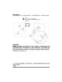
AmazonBasics Desk Monitor Mount
B00MIBN16O
English . . . . . . . . . . . . . . . . . . . . . .3
Français . . . . . . . . . . . . . . . . . . . .17
Deutsch . . . . . . . . . . . . . . . . . . . .31
日本語 . . . . . . . . . . 45
中文. . . . . . . . . . . . . . . . . . . . 59
Italiano . . . . . . . . . . . . . . . . . . . . .72
Español. . . . . . . . . . . . . . . . . . . . .86
2
English
Instruction Manual · English
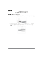
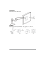
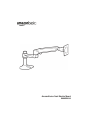
AmazonBasics Desk Monitor Mount
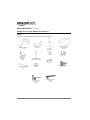
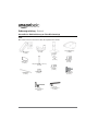
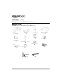
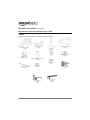
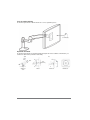
Contents
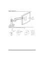
Make sure that the package contains the following parts:
Upper arm
(1 pc)
Lower arm
(1 pc)
Grommet bracket
(1 pc)
Base
(1 pc)
M4 × 10 mm screw
(4 pcs)
Bracket cover
(1 pc)
M8 (1/4-20UNC, 3 inch)
(1 pc)
M3 x 6 mm
screw
1 (pc)
Cable tie
(2 pcs)
M4 × 10 mm knob
(4 pcs)
Wing nut
(1 pc)
4 mm Allen wrench
(1 pc)
2.5 mm Allen wrench
(1 pc)
3
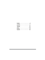
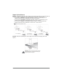
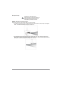
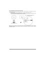
Supported monitor weights
Your monitor mount supports a monitor of the following weight:
lbs
kg
5 to 25 lbs
(2.3 to 11.3 kg)
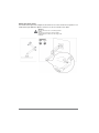
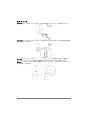
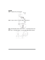
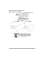
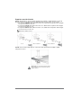
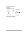
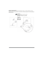
Monitor adjustments
Your monitor mount lets you adjust the monitor viewing angle, height, tilt, and orientation
(portrait or landscape).
360°
70°
360°
13 in.
(330 mm)
180°
5°
Viewing angle
4
Height
Tilt
Orientation
Assembly Instructions
Caution: Because mounting surface materials
can vary widely, make sure that the mounting
surface is strong enough to handle your monitor
mount and the monitor.
Step 1: Choose a mounting option.
You can mount the monitor arm using the:
• Desk-clamp mount to attach your monitor arm to the edge of a tabletop. Go to
“Desk-clamp mount” on page 6.
• Plate mount to attach your monitor mount to an area that is away from the edge of a
tabletop. This mounting option requires a hole through the mounting surface. Go to
“Plate mount” on page 7.
5
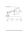
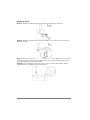
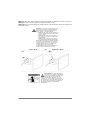
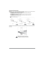
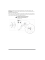
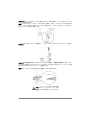
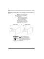
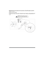
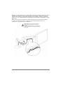
Desk-clamp mount
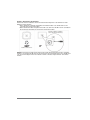
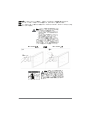
Step A: Determine the thickness of the mounting surface, then use the 4 mm Allen wrench to
adjust the location of the mounting clamp assembly, if necessary.
• The top screw holes on the clamp bracket fit a mounting surface thickness of less than
5/8 in. (1.6 cm).
• The middle screw holes on the clamp bracket fit a mounting surface thickness between
1/4 to 1 5/8 in. (0.6 to 4.1 cm).
• The bottom screw holes on the clamp bracket fit a mounting surface thickness between
1 1/4 to 2 5/8 in (3.2 to 6.7 cm).
4 mm Allen wrench
<3/8 in. (1 cm)
1/2 to 1-3/8 in.
(1.2 to 3.56 cm)
1.5 to 2-3/8 in.
(3.7 to 6.0 cm)
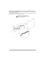
Step B: Slide the mounting clamp assembly onto the mounting surface, then tighten the
clamp.
Caution: Do not rotate the monitor past the
edge of desk. The weight of the monitor may
cause the desk to tip over.
6
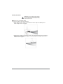
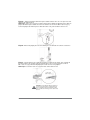
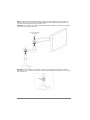
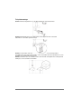
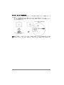
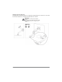
Plate mount
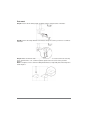
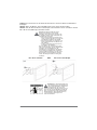
Step A: Remove the mounting clamp assembly from the clamp bracket on the base.
4 mm
Step B: Remove the clamp bracket from the base. Keep the screws you remove. You will use
them later.
4 mm
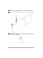
Step C: Make sure that the side of the grommet bracket with recessed screw holes is facing
down. Insert the M8 × 3 in. screw through the square hole in the center of the grommet
bracket.
Note: To keep the 3-inch screw from falling inside the base, temporarily attach the wing nut to
hold it in place.
7
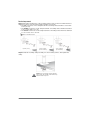
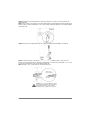
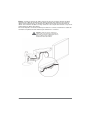
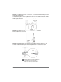
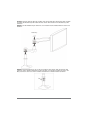
Step D: Attach the grommet bracket to the base with the 3 screws you removed from the
clamp bracket.
Note: If the screws are not flush to the grommet bracket, the grommet bracket is upside down.
Remove these screws and the M8 × 3 in. screw, turn the grommet bracket over, then put all the
screws back in.
4 mm
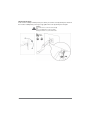
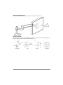
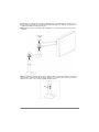
Step E: Remove the clamp plate from the clamp assembly using a Phillips screwdriver.
Step F: Center the base over the top of the hole in the mounting surface, then, from the
bottom of the mounting surface, slide the clamp plate you removed onto the M8 × 3 in. screw.
Secure the clamp plate to the screw with the wing nut.
Note: The M8 × 3 in. screw must be centered in the hole.
0.31 to 2 in.
(8 to 51 mm)
< 2.25 in.
(57 mm)
Caution: For secure arm attachment and to
avoid equipment damage, the base and the
clamp plate must make contact with the
mounting surface on both sides of the hole.
8
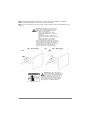
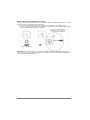
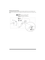
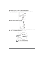
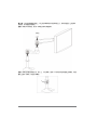
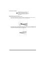
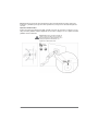
Step 2: Determine the orientation of the monitor
You can mount the monitor in a locked portrait or landscape orientation, or you can leave the
monitor free to rotate 360°.
• If you want the monitor to rotate freely, do not insert the M3 x 6 mm screw.
• If you want the monitor in a locked orientation, insert the M3 x 6 mm screw into the front
of the plate on the upper arm.
Monitor is locked in portrait or
landscape orienation.
Monitor rotates freely.
Note: If you insert the screw, then want to change the monitor’s orientation after you mount the
monitor to the upper arm, you need to remove the monitor from the upper arm and insert or
remove the M3 x 6 mm screw.
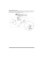
9
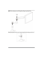
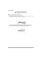
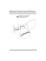
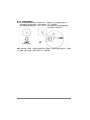
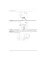
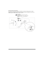
Step 3: Attach the upper arm to the back of the monitor using a Phillips screwdriver.
Note: If a stand is attached to the monitor, remove the stand.
Note: You can use the M4 × 10 mm screws or M4 × 10 mm knobs to attach the arm to the
monitor.
Caution: The mounting screw holes on the
back of the monitor may require screws of a
different type or length than the provided
M4 × 10 mm screws or knobs.
• Using screws of that are too big in
diameter will damage the screw holes on
the monitor.
• Using screws that are too small or too
short may cause the monitor to fall off the
arm.
• Using screws that are too long may
damage the interior of the monitor.
Before you attach the monitor to the upper arm,
make sure that the provided screws or knobs fit
the screw holes on the back of the monitor.
If the provided screws or knobs do not fit, refer
to the documentation that came with the
monitor for the correct screw type and size.
M4 × 10 mm screws
OR
M4 × 10 mm knobs
Warning: The upper arm is under
tension and will move up rapidly, on its
own, as soon as the attached monitor is
removed. For this reason, remove the upper
arm, lay the monitor face down on a soft
surface, then remove the monitor. Failure to
follow this instruction may result in serious
personal injury or equipment damage.
10
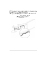
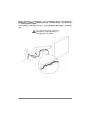
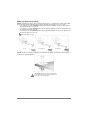
Step 4: Slide the lower arm onto the base. Slide the upper arm over the lower arm, then insert
the bracket cover into the top of the upper arm. The cover should snap into place.
Note: To remove the bracket cover, use a flathead screwdriver to pry off the cover.
Bracket
cover
Note: If the monitor is too high or too low, remove the upper and lower arms. Loosen the screw
on the base ring with the 2.5 mm wrench, slide the ring up or down, then tighten the screw.
11
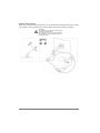
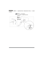
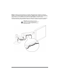
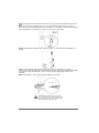
Step 5: Insert the cable ties through the loops on the bottom of the upper arm, route the
monitor cables along the upper arm, then loosely secure the cables to the upper arm with the
cable ties. Do not over-tighten the ties. If the ties are too tight and you try to remove them, you
may damage the monitor cables.
Squeeze the tabs on the lower arm cover to remove the cover, route the monitor cables along
the bottom of the lower arm, then replace the covers.
Caution: Before you tighten the cable ties,
adjust your monitor to the highest position. This
will leave enough slack in the cables for monitor
movement/height adjustment.
Lower arm
cover
ties
ble
a
C
12
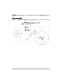
Step 6: Adjust your monitor mount's tension. You can adjust the vertical, tilt, and arm tension
so that the monitor stays in place when you move it.
Adjusting the vertical tension
Tilt the monitor down to access the screw. If the monitor is rising up, loosen the screw by
turning it to the left. If the monitor is falling down, tighten the screw by turning it to the right.
Caution: Do not over-tighten the screw. You
might damage the monitor or your monitor
mount.
4 mm
13
Adjusting the tilt tension
If the monitor is falling forward (screen goes down), loosen the screw by turning it to the left. If
the monitor is falling back (screen goes up), tighten the screw by turning it to the right.
Caution:
Do not remove the screw. The monitor might
fall.
Do not over-tighten the screw. You might
damage the monitor or your monitor mount.
4 mm
14
Adjusting the arm tension
To make the arm easier to move, loosen the screws by turning them to the left. To make the
arm harder to move, tighten the screws by turning them to the right.
Caution:
Do not remove the screws. The monitor might
fall.
Do not over-tighten the screws. You might
damage the monitor or your monitor mount.
2.5 mm
15
Safety and Compliance
IMPORTANT: This product will need tension adjustments after installation is complete. Make
sure that all equipment is properly installed on the product before attempting range of motion
or tension adjustments. Any time equipment is added or changed on this product resulting in a
different mounted weight, you should repeat the adjustment steps to ensure safe and optimum
operation. This product should move smoothly and easily through the full range of motion and
stay where you set it. If movement is difficult or the product does not stay where you set it,
follow the adjustment instructions to loosen or tighten the tension to create a smooth, easy
motion. Depending on your product and the adjustment, it may take many turns to notice a
difference.
© 2014 Amazon.com, Inc. or its affiliates. All Rights reserved. Amazon and the AmazonBasics logo are trademarks of Amazon.com, Inc. or its
affiliates.
Made in China
16
Français
Manuel d’utilisation · Français
Support de Bureau pour Moniteur AmazonBasics
Contenu
Assurez-vous que l’emballage contient les pièces suivantes :
Bras supérieur
(1 pce)
Bras inférieur
(1 pce)
Plaque de fixation
passe-câble
(1 pce)
Base
(1 pce)
Couvercle de
plaque de
fixation
(1 pce)
Vis M4 x 10 mm
(4 pcs)
M8 (1/4-20UNC,
7,62 cm/3 po (1 pce)
Vis M3 x 6 mm
(1 pce)
Attaches de câbles
(2 pcs)
Bouton M4 x 10 mm
(4 pcs)
Vis papillon
(1 pce)
Clé hexagonale
de 4 mm
(1pce)
Clé hexagonale de
2,5 mm
(1pce)
17
Le moniteur supporté pèse
Votre support de moniteur supporte un moniteur de poids suivant :
kg
lb
2,3 a 11,3 kg
(5 à 25 lb)
Réglages du moniteur
Votre support de moniteur vous laisse régler l’ange de vue, la hauteur, l’inclinaison, et
l’orientation (portrait ou paysage).
360°
70°
360°
330 mm
(13 po)
180°
5°
Angle de vue
18
Hauteur
Inclinaison
Orientation
Notice d’assemblage
Attention : Puisque que les matériaux de
surface peuvent varier largement, assurez-vous
que la surface de montage est suffisamment
solide pour supporter votre support de moniteur
et le moniteur.
Étape 1 : Choisissez une option de montage.
Vous pouvez monter le bras de moniteur en utilisant le :
• Support à pince de bureau pour attacher votre bras de moniteur au bord d’un dessus de
table. Allez à «Support à pince de bureau» à la page 20.
• Support de plaque pour attacher votre support de moniteur à une surface qui est
éloignée du bord de dessus de table. Cette option de montage nécessite un trou à
travers la surface de montage. Allez à «Support de plaque» à la page 21.
19
Support à pince de bureau
Étape A : Déterminez l’épaisseur de la surface de montage, puis utilisez la clé hexagonale de
4 mm pour régler l’emplacement de l’ensemble pince de montage, si nécessaire.
• Les trous de vis du haut sur la plaque de fixation de pince conviennent pour une
épaisseur de surface de montage de moins de 1,6 cm (5/8 po).
• Les trous de vis du milieu sur la plaque de fixation de pince conviennent pour une
épaisseur de surface de montage de 0,6 à 4,1 cm (1/4 à 1 5/8 po).
• Les trous de vis du bas sur la plaque de fixation de pince conviennent pour une
épaisseur de surface de montage de 3,2 à 6,7 cm (1 1/4 et 2 5/8 po).
Clé hexagonale de 4 mm
< 1 cm (3/8 po)
1,2 à 3,56 cm
(1/2 à 1-3/8 po)
3,7 à 6,0 cm
(1,5 à 2-3/8 po)
Étape B : Glissez l’ensemble pince de montage sur la surface de montage, puis serrez
la pince.
Attention : Ne pas tourner le moniteur au-delà
du bord du bureau. Le poids du moniteur peut
causer le bureau de basculer.
20
Support de plaque
Étape A : Retirez l’ensemble pince de montage du support de pince sur la base.
4 mm
Étape B : Retirez le support de pince de la base. Gardez les vis que vous enlevez. Vous les
utiliserez plus-tard.
4 mm
Étape C : Assurez-vous que le côté de la plaque de fixation passe-câble avec les trous de vis
en retrait est orienté vers le bas. Insérez la vis M8 x 7,62 cm (3 po) à travers le trou carré au
centre de la plaque de fixation passe-câble.
Remarque : Pour empêcher que la vis de 7,62 cm (3 po) ne tombe dans la base, attachez
temporairement la vis papillon pour la tenir en place.
21
Étape D : Attachez la plaque de fixation passe-câble à la base avec les 3 vis que vous avez
enlevées du support pince.
Remarque : Si les vis ne sont pas au même niveau que la plaque de fixation passe-câble, la
plaque de fixation passe-câble est à l’envers. Retirez ces vis et la vis M8 x 7,62 cm (3 po),
tournez la plaque de fixation passe-câble de l’autre côté, puis remettez toutes les vis.
4 mm
Étape E : Enlevez la plaque pince de l’ensemble pince en utilisant un tournevis cruciforme.
Étape F : Centrez la base sur le haut du trou dans la surface de montage, puis, à partir du
bas de la surface de montage, glissez la plaque pince que vous avez enlevée sur la vis
M8 x 7,62 cm (3 po). Attachez la plaque pince à la vis avec la vis papillon.
Remarque : La vis M8 x 7,62 cm (3 po) doit être centrée dans le trou.
8 à 51 mm
(0,31 à 2 po)
57 mm
(2,25 po)
Attention : Pour attacher l’attache de bras et
pour éviter tout dommage à l’équipement, la
base et la plaque pince doivent faire contact
avec la surface de montage sur les deux côtés
du trou.
22
Étape 2 : Déterminez l’orientation du moniteur
Vous pouvez monter le moniteur dans une orientation portrait ou paysage verrouillée, ou vous
pouvez laisser le moniteur libre de tourner 360°.
• Si vous voulez que le moniteur tourne librement, n’insérez pas la vis M3 x 6 mm.
• Si vous voulez le moniteur dans une orientation verrouillée, insérez la vis M3 x 6 mm dans
le devant de la plaque sur le bras supérieur.
Le moniteur est verrouillé dans
l’orientation portrait ou paysage.
Le moniteur tourne librement.
Monitor rotates freely.
Remarque : Si vous insérez la vis, puis voulez changer l’orientation du moniteur après que
vous montez le moniteur au bras supérieur, il vous faut retirer le moniteur du bras supérieur et
insérer ou retirer la vis M3 x 6 mm.
23
SÉtape 3 : Attachez le bras supérieur au dos du moniteur en utilisant un tournevis cruciforme.
Remarque : Si un socle est attaché au moniteur, retirez le socle.
Remarque : Vous pouvez utiliser les vis M4 x 10 mm ou boutons M4 x 10 mm pour attacher le
bras au moniteur.
Attention : Les trous de vis de montage sur le
dos du moniteur peuvent nécessiter des vis
d’un autre type ou d’une longueur différente
que les boutons ou vis M4 x 10 mm.
• L’utilisation de vis qui sont trop grandes en
diamètre endommagera les trous de vis
sur le moniteur.
• L’utilisation de vis qui sont trop petites ou
trop courtes peut causer le moniteur de
tomber du bras.
• L’utilisation de vis qui sont trop longues
peut endommager l’intérieur du moniteur.
Avant d’attacher le moniteur au bras supérieur,
assurez-vous que les boutons ou vis fournies
conviennent pour les trous de vis au dos du
moniteur. Si les boutons ou vis fournies ne
conviennent pas, reportez-vous à la
documentation fournie avec le moniteur pour
obtenir le type et la taille corrects de vis.
Vis M4 x 10 mm
OU
boutons M4 x 10 mm
Avertissement : Le bras supérieur est
sous tension et se déplacera rapidement
vers le haut, de lui-même, aussitôt que
le moniteur attaché est enlevé. Pour cette
raison, enlevez le bras supérieur, posez le
moniteur avec la face dirigée vers le bas sur
une surface douce, puis enlevez le moniteur. Le
non-respect de cette directive peut entraîner
des blessures graves ou endommager
l’équipement.
24
Étape 4 : Glissez le bras inférieur sur la base. Glissez le bras supérieur au-dessus du bras
inférieur, puis insérez le couvercle de plaque de fixation dans le haut du bras supérieur. Le
couvercle devrait s’emboîter en place avec un clic.
Remarque : Pour enlever le couvercle de plaque de fixation, utilisez un tournevis à tête plate
pour l’enlever en faisant faire levier.
Couvercle de plaque
de fixation
Remarque : Si le moniteur est trop haut ou trop bas, retirez les bras supérieur et inférieur.
Desserrez la vis sur la base avec la clé de 2,5 mm, glissez la bague vers le haut ou vers le bas,
puis serrez la vis.
25
Étape 5 : Insérez les attaches de câbles à travers les boucles sur le bas du bras supérieur,
acheminez les câbles du moniteur le long du bras supérieur, puis attachez sans serrer les
câbles au bras supérieur avec les attaches de câbles. Ne pas trop serrer les attaches de
câbles. Si les attaches de câbles sont trop serrées et vous essayez de les enlever, vous pouvez
endommager les câbles du moniteur.
Pincez les languettes sur le bras inférieur pour enlever le couvercle, acheminez les câbles du
moniteur le long du bas du bras inférieur, puis remettez les couvercles.
Attention : Avant de serrer les attaches de
câbles, réglez votre moniteur sur la position la
plus haute. Ceci laissera suffisamment de mou
dans les câbles pour le réglage en
hauteur/mouvement du moniteur.
Couvercle
bras infé du
rieur
e
sd
e
h
s
ac
Att câble
26
Étape 6 : Réglez la tension de votre support de moniteur. Vous pouvez régler la tension
verticale, d’inclinaison, et de bras pour que le moniteur reste en place quand vous le déplacez.
Réglage de la tension verticale
Inclinez le moniteur vers le bas pour avoir accès aux vis. Si le moniteur s’élève, desserrez la vis
en la tournant vers la gauche. Si le moniteur descend, serrez la vis en la tournant vers la droite.
Attention : Avant de serrer les attaches de
câbles, réglez votre moniteur sur la position la
plus haute. Ceci laissera suffisamment de mou
dans les câbles pour le réglage en
hauteur/mouvement du moniteur.
4 mm
27
Réglage de la force de basculement
Si le moniteur bascule vers l’avant (l’écran descend), desserrez la vis en la tournant vers la
gauche. Si le moniteur bascule vers l’arrière (l’écran s’élève), serrez la vis en la tournant vers la
droite.
Attention :
Ne pas enlever les vis. Le moniteur pourrait
tomber.
Ne pas trop serrer les vis. Vous pourriez
endommager le moniteur ou votre support de
moniteur.
4 mm
28
Réglage de la tension du bras
Pour rendre le bras plus facile à déplacer, desserrez les vis en les tournant vers la gauche. Pour
rendre le bras plus difficile à déplacer, serrez les vis en les tournant vers la droite.
Attention :
Ne pas enlever les vis. Le moniteur pourrait
tomber.
Ne pas trop serrer les vis. Vous pourriez
endommager le moniteur ou votre support de
moniteur.
2,5 mm
29
Sécurité et conformité
IMPORTANT : Ce produit nécessitera des réglages de tension une fois que l’installation est
finie. Assurez-vous que tout l’équipement est correctement installé sur le produit avant de
tenter les réglages d’amplitude de mouvement ou de tension. Chaque fois qu’un équipement
est ajouté ou changé sur ce produit résultant en un poids monté différent, vous devriez répéter
les étapes de réglage pour assurer un fonctionnement sûr et optimum. Ce produit devrait se
déplacer en douceur et facilement à pleine amplitude de mouvement et rester où vous le
réglez. Si le mouvement est difficile ou le produit ne reste pas où vous l’avez réglé, suivez les
instructions de réglage pour desserrer ou serrer la tension pour créer un déplacement facile en
douceur. Suivant votre produit et le réglage, cella peut demander de nombreux tours pour
remarquer une différence.
© 2014 Amazon.com, Inc. ou ses filiales. Tous droits réservés. Amazon et le logo AmazonBasics sont des marques de commerce
d’Amazon.com, Inc. ou de ses fi liales.
Fabriqué en Chine
30
Deutsch
Bedienungsanleitung · Deutsch
AmazonBasics Monitorhalterung zur Schreibtischmontage
Inhalt
Bitte stellen Sie sicher, dass das Paket die folgenden Teile enthält:
Oberer Arm
(1 Stck.)
Unterer Arm
(1 Stck.)
Schraubhalterung
(1 Stck.)
Fuß
(1 Stck.)
Abdeckung
(1 Stck.)
M4 × 10 mm
Schraube
(4 Stck.)
M8 (1/4-20 UNC, 7,62 cm)
(1 Stck.)
M3 x 6 mm
Schraube
(1 Stck.)
Kabelbinder
(2 Stck.)
M4 × 10 mm
Schraubknopf
(4 Stck.)
Flügelmutter
(1 Stck.)
4 mm
Imbusschlüssel
(1 Stck.)
2,5 mm
Imbusschlüssel
(1 Stck.)
31
Unterstützte Monitorgewichte
Die Monitorhalterung unterstützt einen Monitor mit folgendem Gewicht:
kg
2,3 bis 11,3 kg
Monitoreinstellungen
Die Monitorhalterung ermöglicht die Einstellung des Sichtwinkels, der Höhe, der Neigung und
der Ausrichtung (vertikal oder horizontal) des Monitors.
360°
70°
360°
13 in.
(330 mm)
180°
5°
Sichtwinkel
32
Höhe
Neigung
Ausrichtung
Montageanleitung
Vorsicht: Da die Beschaffenheit der
Montageoberflächen sehr unterschiedlich sein
kann, muss sichergestellt werden, dass die
Montageoberfläche stark genug ist, um die
Monitorhalterung mit Monitor zu halten.
Schritt 1: Auswahl einer Montageoption.
Der Monitorarm kann auf folgende Weise montiert werden:
• Schreibtisch-Klemmmontage zur Befestigung des Monitorarms am Rand der Tischplatte.
Siehe „Schreibtisch-Klemmmontage“ auf Seite 34.
• Tischplattenmontage zur Befestigung des Monitorarms an einer anderen Stelle als am
Rand der Tischplatte. Für diese Montageoption ist ein Loch durch die Montageoberfläche
erforderlich. Siehe „Tischplattenmontage“ auf Seite 35.
33
Schreibtisch-Klemmmontage
Schritt A: Die Dicke der Montageoberfläche bestimmen und dann den 4 mm Imbusschlüssel
verwenden, um ggf. die Montageklemme einzustellen.
• Die oberen Schraublöcher an der Klemmhalterung sind passend für eine
Oberflächendicke von weniger als 1,6 cm.
• Die mittleren Schraublöcher an der Klemmhalterung sind passend für eine
Oberflächendicke von 0,6 bis 4,1 cm.
• Die unteren Schraublöcher an der Klemmhalterung sind passend für eine
Oberflächendicke von 3,2 bis 6,7 cm.
4 mm Imbusschlüssel
1 cm
1,2 bis 3,56 cm
3,7 bis 6,0 cm
Schritt B: Die Montageklemme auf die Montageoberfläche schieben und dann die Klemme
festdrehen.
Vorsicht: Monitor nicht über die Tischkante
hinaus drehen. Das Gewicht des Monitors kann
ein Umkippen des Schreibtisches verursachen.
34
Tischplattenmontage
Schritt A: Die Montageklemme von der Klemmhalterung am Fuß abnehmen.
4 mm
Schritt B: Klemmhalterung vom Fuß abnehmen. Die abgenommenen Schrauben
aufbewahren. Sie werden später benötigt.
4 mm
Schritt C: Sicherstellen, dass die Seite der Schraubhalterung mit den eingesenkten
Schraublöchern nach unten zeigt. Die M8 × 7,62 cm Schraube durch das quadratische Loch in
der Mitte der Schraubhalterung einsetzen.
Hinweis: Damit die 7,62 cm Schraube nicht in den Fuß fällt, die Flügelmutter vorübergehend
anbringen, um die Schraube festzuhalten.
35
Schritt D: Schraubhalterung mit den 3 Schrauben, die von der Klemmhalterung abgenommen
wurden, am Fuß befestigen.
Hinweis: Wenn die Schrauben nicht bündig an der Schraubhalterung anliegen, wurde die
Schraubhalterung verkehrt herum angebracht. In dem Falle müssen diese Schrauben und die
M8 × 7,62 cm Schraube entfernt, die Schraubhalterung umgedreht und dann alle Schrauben
wieder angebracht werden.
4 mm
Schritt E: Klemmplatte von der Klemmhalterung unter Verwendung eines
Kreuzschraubenziehers abnehmen.
Schritt F: Den Fuß über dem Loch in der Montageoberfläche zentrieren und dann von der
Unterseite der Montageoberfläche die zuvor entfernte Klemmplatte auf die M8 × 7,62 cm
Schraube schieben. Die Klemmplatte mit der Flügelmutter an der Schraube befestigen.
Hinweis: Die M8 × 7,62 cm Schraube muss im Loch zentriert sein.
8 bis
51 mm
57 mm
Vorsicht: Um eine sichere Befestigung des
Arms zu gewährleisten und Beschädigungen zu
vermeiden, müssen der Fuß und die
Klemmplatte mit der Montageoberfläche auf
beiden Seiten des Loches Kontakt haben.
36
Schritt 2: Ausrichtung des Monitors
Der Monitor kann in vertikaler oder horizontaler Ausrichtung fixiert oder unfixiert um 360°
drehbar montiert werden.
• Wenn der Monitor unfixiert und drehbar verwendet werden soll, darf die M3 x 6 mm
Schraube nicht eingesetzt werden.
• Wenn der Monitor fixiert ausgerichtet werden soll, dann muss die M3 x 6 mm Schraube in
die Vorderseite der Platte am oberen Arm eingesetzt werden.
Monitor ist fixiert in vertikaler
oder horizontaler Ausrichtung.
Monitor dreht sich frei.
Hinweis: Wenn die Schraube eingesetzt wurde und die Ausrichtung des Monitors geändert
werden soll, nachdem der Monitor an den oberen Arm montiert wurde, dann muss der Monitor
vom oberen Arm abgenommen und die M3 x 6 mm Schraube eingesetzt bzw. entnommen
werden.
37
Schritt 3: Den oberen Arm an der Rückseite des Monitors mit einem Kreuzschraubenzieher
befestigen.
Hinweis: Wenn der Monitor einen Standfuß besitzt, muss dieser entfernt werden.
Hinweis: Um den Arm am Monitor zu befestigen, können die M4 x 10 mm Schrauben oder die
M4 x 10 mm Schraubknöpfe verwendet werden.
Vorsicht: Für die Schraublöcher an der
Rückseite des Monitors sind eventuell
Schrauben einer anderen Art oder Länge als
die enthaltenen M4 x 10 mm Schrauben oder
Schraubknöpfe notwendig.
• Bei der Verwendung von Schrauben mit
einem zu großen Durchmesser werden die
Schraublöcher im Monitor beschädigt.
• Bei der Verwendung von zu kleinen or zu
kurzen Schrauben kann der Monitor vom
Arm abfallen.
• Zu lange Schrauben können das Innere
des Monitors beschädigen.
Bevor der Monitor am oberen Arm befestigt
wird, ist sicherzustellen, dass die mitgelieferten
Schrauben oder Schraubknöpfe in die
Schraublöcher an der Rückseite des Monitors
passen. Wenn die mitgelieferten Schrauben
oder Schraubknöpfe nicht passen, bitte in der
Beschreibung, die mit dem Monitor geliefert
wurde, die richtige Schraubenart und -größe
nachlesen.
M4 x 10 mm Schrauben
ODER
M4 x 10 mm Schraubknöpfe
Achtung: Der obere Arm befindet sich
unter Spannung und schnellt allein nach
oben, sobald der Monitor entfernt wird.
Aus diesem Grund muss der obere Arm
entfernt, der Monitor mit der Vorderseite nach
unten auf eine weiche Oberfläche gelegt und
dann erst der Monitor abgenommen werden.
Ein Nichtbefolgen dieser Anleitung kann zu
schweren Körperverletzungen und
Sachschaden führen.
38
Schritt 4: Unteren Arm auf den Fuß schieben. Den oberen Arm über den unteren Arm schieben
und dann die Abdeckung in die Oberseite des oberen Arms drücken. Die Abdeckung sollte
einrasten.
Hinweis: Um die Abdeckung zu entfernen, sie mit einem Flachschraubenzieher lockern und
abheben.
Abdeckung
Hinweis: Wenn der Monitor zu hoch oder zu niedrig ist, den oberen und den unteren Arm
entfernen. Die Schraube am Ring des Fußes mit dem 2,5 mm Imbusschlüssel lockern, den
Ring nach oben oder nach unten schieben und dann die Schraube wieder festziehen.
39
Schritt 5: Die Kabelbinder durch die Ösen an der Unterseite des oberen Arms führen, die
Monitorkabel am oberen Arm entlangführen und sie dann mit den Kabelbindern locker am
oberen Arm befestigen. Die Kabelbinder nicht zu stramm ziehen. Wenn die Kabelbinder zu
stramm sind und dann entfernt werden sollen, können die Monitorkabel beschädigt werden.
Die Abdeckung am unteren Arm leicht zusammendrücken und entfernen, die Monitorkabel an
der Unterseite des unteren Arms entlangführen und dann die Abdeckung wieder einsetzen.
Vorsicht: Vor dem Festziehen der Kabelbinder
den Monitor in die höchste Position bringen.
Dadurch bleibt genügend Spielraum in den
Kabeln, damit der Monitor bewegt bzw.
höhenverstellt werden kann.
Abdecku
n
unteren Ag am
rm
Ka
40
de
lbin
e
b
r
Schritt 6: Einstellen der Spannung der Monitorhalterung. Die vertikale, Neigungs- und
Armspannung kann eingestellt werden, damit der Monitor an Ort und Stelle bleibt, wenn er
bewegt wird.
Einstellen der vertikalen Spannung
Monitor nach unten neigen, um Zugriff auf die Schraube zu erhalten. Wenn sich der Monitor
nach oben bewegt, die Schraube durch Linksdrehung lockern. Wenn sich der Monitor nach
unten senkt, die Schraube durch Rechtsdrehung festziehen.
Vorsicht: Vor dem Festziehen der Kabelbinder
den Monitor in die höchste Position bringen. Die
Schraube nicht zu fest ziehen. Dadurch kann
der Monitor oder die Monitorhalterung
beschädigt werden.
4 mm
41
Einstellen der Neigungsspannung
IWenn der Monitor nach vorn fällt (der Bildschirm senkt sich nach unten), die Schraube durch
Linksdrehung lockern. Wenn der Monitor nach hinten fällt (der Bildschirm bewegt sich nach
oben), die Schraube durch Rechtsdrehung festziehen.
Vorsicht:
Die Schraube nicht entfernen. Dadurch kann
der Monitor herunterfallen.
Die Schraube nicht zu fest ziehen. Dadurch
kann der Monitor oder die Monitorhalterung
beschädigt werden.
4 mm
42
Einstellen der Armspannung
Damit sich der Arm leichter bewegen lässt, die Schrauben durch Linksdrehung lockern. Damit
sich der Arm schwerer bewegen lässt, die Schrauben durch Rechtsdrehung festziehen.
Vorsicht:
Die Schrauben nicht entfernen. Dadurch kann
der Monitor herunterfallen.
Die Schrauben nicht zu fest ziehen. Dadurch
kann der Monitor oder die Monitorhalterung
beschädigt werden.
2,5 mm
43
Sicherheit und Compliance
WICHTIG: Bei diesem Produkt muss nach der Installation die Spannung eingestellt werden. Es
ist sicherzustellen, dass alle Geräte richtig am Produkt installiert wurden, bevor Bewegungsund Spannungseinstellungen vorgenommen werden. Wenn zusätzliche Geräte am Produkt
befestigt oder Änderungen vorgenommen werden und dadurch ein anderes Gewicht an der
Halterung anliegt, müssen alle Einstellungsschritte wiederholt werden, um eine sichere und
optimale Verwendung zu gewährleisten. Dieses Produkt sollte sich reibungslos und leicht
durch den gesamten Bewegungsbereich bewegen lassen und an Ort und Stelle bleiben, wenn
losgelassen. Wenn sich das Produkt schwer bewegen lässt oder nicht an Ort und Stelle bleibt,
muss die Einstellungsanleitung erneut befolgt werden, um die Spannung zu lockern bzw. zu
verstärken, um eine reibungslose und leichte Bewegung zu erzielen. Je nach Produkt und
Einstellung kann ein Unterschied eventuell erst nach mehreren Bewegungen und Drehungen
festgestellt werden.
© 2014 Amazon.com, Inc. oder seine verbundenen Unternehmen. Alle Rechte vorbehalten. Amazon und das AmazonBasics-Logo sind
Marken von Amazon.com, Inc. oder seinenverbundenen Unternehmen.
Hergestellt in China
44
ìŽñ{åÍ
取扱説明書 · 日本語
Amazon ベーシック デスクモニターアーム
梱包されているもの
以下の部品がパッケージに含まれているかご確認ください :
上部アーム
(1 個)
下部アーム
(1 個)
グロメットブラケット
(1 個)
ベース
(1 個)
M4 × 10 mm ネジ
(4 個)
ブラケットカバー
(1 個)
M8 (1/4-20UNC、7.62 cm
(1 個)
M3 x 6 mm ネジ 1
(個)
結束バンド
(2 個)
M4 × 10 mm ノブ
(4 個)
ウィングナット
(1 個)
4 mm 六角レンチ
(1 個)
2.5 mm 六角レンチ
(1 個)
45
許容重量
モニターアームの許容重量は以下の通りです。
kg
2.3 ~ 11.3 kg
モニターの調整
モニターアームでは、モニターの角度、高さ、チルト、回転(縦、横)を調整することができ
ます。
360 度
70 度
360 度
13 in.
(330 mm)
180 度
5度
角度
46
高さ
チルト
回転
組立説明書
注意:設置表面の素材にばらつきがあるた
め、設置表面がモニターアームとモニター
の設置に十分耐えられることを確認してく
ださい。
ステップ 1: 設置オプションを選択します。
以下の方法でモニターアームを設置することができます :
• 卓上の端にモニターアームを取り付けるクランプ式。48 ページの「クランプ式」へ移動。
• 卓上の端から離れた場所にモニターアームを取り付けるグロメット式。s この設置オ
プションは、設置表面に穴を開ける必要があります。49 ページの「グロメット式」
へ移動。
47
クランプ式
ステップ A: 設置表面の厚さを測り、必要に応じて 4mm 六角レンチを使用し、クランプを取
り付ける場所を調整します。
• クランプブラケットの一番上のネジ穴は、厚さ 1.6 cm 未満の設置表面用です。
• クランプブラケットの真ん中のネジ穴は、厚さ 0.6 ~ 4.1 cm の設置表面用です。
• クランプブラケットの一番下のネジ穴は、厚さ 3.2 ~ 6.7 cm の設置表面用です。
4 mm 六角レンチ
<1 cm
1.2 ~ 3.56 cm
3.7 ~ 6.0 cm
ステップ B: 設置用クランプアセンブリを設置表面に差し入れ、クランプを締めます。
注意:卓上の端より先までモニターを回転させ
ないでください。モニターの重さで机が倒れる
原因となることがあります。
48
グロメット式
ステップ A: ベースのクランプブラケットから設置用クランプアセンブリを取り外します。
4 mm
ステップ B: ベースからクランプブラケットを取り外します。取り外したネジは後ほど使用す
るため保管しておきます。
4 mm
ステップ C: グロメットブラケットの埋め込まれたネジ穴のある面が下になるよう確認しま
す。グロメットブラケットの中央にある四角い穴に M8 × 7.62 cm のネジを挿入します。
注記:ベースの中に 7.62 cm のネジが落ちないようにするため、一時的にウィングナットを
付け仮留めしておきます。
49
ステップ D: クランプブラケットから取り外したネジ 3 本を使用し、ベースにグロメットブラ
ケットを取り付けます。
注記:ネジがグロメットブラケットから見えない場合、グロメットブラケットは上下逆さまに
なっています。そのネジと M8 × 7.62 cm ネジを取り外し、グロメットブラケットをひっくり
返し、すべてのネジを付け直します。
4 mm
ステップ E: プラスドライバーを使用して、クランプアセンブリからクランププレートを取り
外します。
ステップ F: 設置表面の穴の上に対しベースを中心に配置し、設置表面の裏側から M8 × 7.62
cm のネジを取り外したクランププレートをスライドして差し入れます。ウィングナットを使
用してネジに対してクランププレートを固定します。
注記:M8 × 7.62 cm ネジは穴の中心に配置しなければなりません。
8 ~ 51 mm
57 mm
注意:アームをしっかりと固定し、装備の損傷
を避けるため、ベースとクランププレートは設
置表面の穴の両面に接触していなければなりま
せん。
50
ステップ 2: モニターの回転の決定
モニターを縦方向または横方向に固定したり、360 度自由に回転させるように調整することが
できます。
• モニターを自由に回転させたい場合、M3 x 6 mm ネジは使用しないでください。
• モニターを固定させたい場合、M3 x 6 mm ネジを上部アームのプレートの前面に M3 x 6
mm ネジを挿入します。
モニターは縦または横に固定さ
れます。
モニターを自由に回転するこ
とができます。
注記:ネジを挿入し、上部アームにモニターを設置した後に、モニターの回転を変えたい場合
には、上部アームから一旦モニターを取り外し、M3 x 6 mm ネジを挿入するか、取り外しま
す。
51
ステップ 3: プラスドライバーを使用し、上部アームをモニターの裏面に取り付けます。
注記:モニターにスタンドが付いている場合には、そのスタンドを取り外します。
注記:アームをモニターに取り付ける際、M4 × 10 mm ネジか M4 × 10 mm ノブのどちらかを
使用することができます。
注意:モニターの裏面にある設置用のネジ穴に
は、付属の M4 × 10 mm ネジやノブとは別の種
類のネジが必要となる場合があります。
• モニターのネジ穴の直径より大きいネジ
を使用した場合、ネジ穴を損傷する恐れ
があります。
• モニターのネジ穴の直径より小さいネジ
を使用した場合、モニターがアームから
落下する原因となる恐れがあります。
• 長すぎるネジを使用した場合、モニター
のインテリアを損傷する恐れがあります。
上部アームにモニターを取り付ける前に、モニ
ターの裏面のネジ穴に付属のネジやノブが合う
かどうか確認してください。付属のネジやノブ
が合わない場合、モニター用の取扱説明書で正
しいネジの種類やサイズを確認してください。
M4 × 10 mm ネジ、
または
M4 × 10 mm ノブ
警告 : 上部アームには張力が働いて
いるため、取り付けているモニター
を外すと同時に急激に持ち上がりま
す。そのため、上部アームからモニターを
取り外す際にはモニターを柔らかいものを
用意し、その上でモニター面を下に向けて
行なってください。この指示に従わない場
合、深刻な負傷や装備の損傷を招く恐れが
あります。
52
ステップ 4: ベースに下部アームを差し入れます。下部アームの上に上部アームを差し入れ、
上部アームの上にブラケットカバーを挿入します。カバーはぴったりとはまるようになってい
ます。
注記:ブラケットカバーを取り外すには、マイナスドライバーでカバーを持ち上げるように取
り外します。
ブラケッ
トカバー
注記:モニターの位置が高すぎたり、低すぎたりする場合、上部アームや下部アームを取り外
し調整します。2.5mm のレンチを使用して、ベースリングのネジを緩め、リングを上下にス
ライドさせて調節した後、ネジを締めます。
53
ステップ 5: 上部アームの下にあるループに結束バンドを差し入れ、上部アームに沿ってモニ
ターケーブルを這わせます。結束バンドを使用し、余裕を持ってケーブルを上部アームに固定
します。結束バンドをきつく締めすぎないでください。結束バンドをきつく締めすぎた場合、
取り外す際にモニターケーブルに損傷を与える恐れがあります。
下部アームカバーのタブを両側から押して、カバーを取り外し、下部アームの下にモニター
ケーブルを這わせ、カバーを付け直します。
注意:結束バンドを締める前に、一番高い位置
にモニターを調整します。この操作により、
モニターの移動 / 高さの調整の際、ケーブルに
十分な余裕ができます。
下部アー
ム
カバー
ンド
バ
結束
54
ステップ 6: モニターアームのテンションの調整を行ないます。移動した際にその場所にモニ
ターがその場所に固定されるよう、上下、チルト、アームテンションを調整することができま
す。
上下テンションの調整
ネジに届くようモニターを下向きに傾けます。モニターを上に上げる場合、ネジを左に回し緩
めます。モニターを下に下げる場合、ネジを右に回し締めます。
注意:結束バンドを締める前に、一番高い位置
にモニターを調整します。この操作により、モ
ニターの移動 / 高さの調整の際、ケーブルに十
分な余裕ができます。
4 mm
55
チルトの調整
モニターを前に傾ける場合(画面が下向き)
、ネジを左に回し緩めます。モニターを後ろに傾
ける場合(画面が上向き)
、ネジを右に回し締めます。
注意:
ネジを取り外さないでください。モニターが落
下する恐れがあります。
ネジをきつく締めすぎないでください。モニ
ターやモニターアームに損傷を与える恐れがあ
ります。
4 mm
56
アームの調整
アームを動かしやすくするには、ネジを左に回して緩めます。アームを固定するには、ネジを
右に回して締めます。
注意:
ネジを取り外さないでください。モニターが落
下する恐れがあります。
ネジをきつく締めすぎないでください。モニ
ターやモニターアームに損傷を与える恐れがあ
ります。
2.5 mm
57
安全性とコンプライアンス
重要 : 本製品は、設置完了後にテンションの調整が必要となります。移動範囲を試したり、テ
ンションの調整を行なう前に、すべての装備が本製品に対して適切に設置されていることを確
認してください。本製品に対し、重量の異なる装備を追加したり変更する場合は、必ずこの調
整手順を繰り返し、操作の安全性や最適性を確認します。本製品は、移動範囲内をスムーズか
つ簡単に移動することができ、セットした場所に固定できるようになっています。製品がス
ムーズに移動しない場合やセットした場所に固定できない場合、調整方法に従ってテンション
を緩めたり、締めたりすることにより、スムーズかつ簡単に移動できるようにします。ご使用
の製品や調節の仕方により、違いを感じるまでに何度か調整を行なわなければならない場合が
あります。
© 2014 Amazon.com, Inc.( ま た は関連会社 )。 無断複写 ・ 転載を 禁ず。 Amazon と Amazon ベ ー シ ッ ク の ロ ゴ は、 Amazon.com, Inc. ま た は関連会社
の 商標 で す。
中国製
58
÷–Œƒ
使用说明书 · 中文
亚马逊倍思桌面显示器支架
目录
确保包装中包含下列零部件:
上支撑臂
(1 件)
下支撑臂
(1 件)
孔眼托架
(1 件)
底座
(1 件)
托架盖
(1 件)
M4 × 10 毫米螺钉
(4 件)
M8 (1/4-20UNC, 7.62 厘米
(1 件)
M3 x 6 毫米螺钉
(1 件)
束线带
(2 条)
M4 × 10 毫米旋钮
(4 件)
翼形螺帽
(1 件)
4 毫米通用扳手
(1 件)
2.5 毫米通用扳手
(1 件)
59
支撑显示器重量
您的显示器支架可支撑以下重量的显示器:
公斤
2.3 到 11.3 公斤
显示器调节
您的显示器支架能让您调节显示器的观看角度、高度、倾斜度和方向 (人物或风景)。
360°
70°
360°
13 in.
(330 毫米 )
180°
5°
观看角度
60
高度
倾斜度
方向
安装说明
小心:因为安装表面材料之间可能有很大差异,
因此请确保安装表面的坚固程度足以承受您的显
示器支架和显示器。
第 1 步:选择一个安装方案。
您可以使用以下方案来安装显示器支撑臂:
t 桌面夹式安装,将您的显示器支撑臂固定在桌面的边缘处。详情请参见第 62 页的 “桌
面夹式安装”。
t 板式安装,将您的显示器支架固定在远离桌沿的地方。这个安装方案需要在安装表面上
钻一个孔。详情请参见第 63 页的 “板式安装”。
61
桌面夹式安装
步骤 A:确定安装表面的厚度,然后使用 4 毫米的通用扳手来调整固定夹具组件的位置
(若适用)。
• 夹具托架顶部的螺孔适合厚度小于 1.6 厘米的安装表面。
• 夹具托架中间的螺孔适合厚度在 0.6 到 4.1 厘米之间的安装表面。
• 夹具托架底部的螺孔适合厚度在 3.2 到 6.7 厘米之间的安装表面。
4 毫米通用扳手
小于 1 厘米
1.2 到 3.56 厘米
3.7 到 6.0 厘米
步骤 B:将固定夹具组件滑动到安装表面上,然后拧紧夹具。
小心:不要将显示器旋转到桌沿以外。显示器的
重量可能会导致桌子翻到。
62
板式安装
步骤 A:从底座的夹具托架上拆下固定夹具组件。
4 毫米
步骤 B:从底座上拆下夹具托架。保存好您拆下的螺钉。您稍后会用到它们。
4 毫米
步骤 C:确保带有嵌壁式螺钉孔眼托架一侧朝下。将 M8 × 7.62 厘米螺钉插到孔眼托架中间的
方孔中。
注意:为避免 7.62 厘米的螺钉掉进底座中,您可以暂时使用翼形螺帽来将其固定在正确位置。
63
步骤 D 使用您从夹具托架上拆下来的 3 个螺钉将孔眼托架固定到底座上。
注意:如果螺钉无法与孔眼托架齐平,这说明您的孔眼托架是倒置的。拆下这些螺钉和 M8 ×
7.62 厘米螺钉,翻转孔眼托架,然后重新固定所有螺钉。
4 毫米
步骤 E 使用十字螺丝刀从夹具组件上拆下夹板。
步骤 F:使底座中心位于安装表面上的钻孔顶部之上,然后从安装表面的底部将您拆下的夹板滑
到 M8 × 7.62 厘米螺钉上。用翼形螺帽将夹板旋转到螺钉上。
注意:M8 × 7.62 厘米螺钉必须位于螺孔的中心。
8 到 51 毫米
57 毫米
小心:为了固定支撑臂连接以及避免设备损坏,
底座和夹板必须接触到螺孔两侧的安装表面。
64
第 2 步:确定显示器的方向。
您可以在安装显示器时将其锁定在人物或风景方向,或者您也可以让显示器自由旋转 360° 。
• 如果您希望让显示器自由旋转,您便不需要插入 M3 x 6 毫米螺钉。
• 如果您希望将显示器锁定在一个方向,将 M3 x 6 毫米螺钉插到上支撑臂金属板的前方。
显示器被锁定在人物或风景方向。
显示器可自由旋转。
注意:如果您插入了螺钉,但在将显示器安装到上支撑臂上之后希望改变显示器的方向,您需要
从上支撑臂上拆下显示器,并插入或取出 M3 x 6 毫米螺钉。
65
第 3 步:使用十字螺丝刀将上支撑臂固定到显示器背面。
注意:如果显示器上连接了支架,先拆除支架。
注意:您可以使用 M4 × 10 毫米螺钉或 M4 × 10 毫米旋钮来将支撑臂固定在显示器上。
小心:显示器背面的安装螺孔可能需要使用与提
供的 M4 × 10 毫米螺钉或旋钮的类型或长度不
同的螺钉。
• 使用直径过大的螺钉将损坏显示器上的螺
孔。
• 使用过小或过短的螺钉可能导致显示器从
支撑臂上掉落。
• 使用过长的螺钉会使显示器内部受损。
在您将显示器连接到上支撑臂上之前,确保提供
的螺钉或旋钮适合显示器背面的螺孔。如果提供
的螺钉或旋钮不适合,参考显示器附带的文件以
查找正确的螺钉类型和尺寸。
M4 × 10 毫米螺钉
或
M4 × 10 毫米旋钮
警告:上支撑臂承受拉力,因此当您将
与其连接的显示器拆下后,它会迅速自
行上升。鉴于此原因,请首先拆下上支
撑臂,将显示器正面朝下平放在一个柔软表面
上,然后再拆下显示器。不遵守此说明可能会造
成严重的人身伤害或设备损坏。
66
第 4 步:将下支撑臂滑到底座上。将上支撑臂滑动到下支撑臂的上方,将托架盖插入上支撑臂
的顶部。托架盖应扣响到位。
注意:如需拆下托架盖,使用一字螺丝刀将托架盖撬开。
托架盖
注意:如果显示器过高或过低,拆下上、下支撑臂。使用 2.5 毫米扳手松开底圈上的螺钉,将底
圈向上或向下滑动,然后拧紧螺钉。
67
第 5 步:将束线带穿过上支撑臂底部的环,沿着上支撑臂布置显示器线缆,然后用束线带松散
地将线缆固定在上支撑臂上。不要将束线带系的过紧。如果束线带系的过紧,当您尝试移动它们
时,您便有可能损坏显示器线缆。
挤压下支撑臂盖子上的突出部分以拆下盖子,沿着下支撑臂底部布置显示器线缆,然后重新盖上
盖子。
小心:在您尝试系紧束线带之前,将您的显示器
调整到最高位置。这将留下足够的线缆长度,以
使显示器能自由移动 / 进行高度调节。
下支撑臂
盖
带
束线
68
第 6 步:调节您的显示器支架的张力。您可以调节垂直张力、倾斜张力和支撑臂张力,以使显
示器在移动时也能保持正确位置。
调节垂直张力
向下倾斜显示器,以便调节螺钉。如果显示器升起,向左旋转来松开螺钉。如果显示器下降,向
右旋转来拧紧螺钉。
小心:在您尝试系紧束线带之前,将您的显示器
调整到最高位置。这将留下足够的线缆长度,以
使显示器能自由移动 / 进行高度调节。
4 毫米
69
调节倾斜紧度
如果显示器前倾 (屏幕降下),向左旋转来松开螺钉。如果显示器后倾 (屏幕上升),向右旋转
来拧紧螺钉。
小心:
不要拆下螺钉。显示器可能会掉落。
不要过分拧紧螺钉。您可能会损坏显示器或您的
显示器支架。
4 毫米
70
调节支撑臂张力
为使支撑臂更易于移动,向左旋转来松开螺钉。为使支撑臂更难以移动,向右旋转来拧紧螺钉。
小心:
不要拆下螺钉。显示器可能会掉落。
不要过分拧紧螺钉。您可能会损坏显示器或您的
显示器支架。
2.5 毫米
安全与合规
重要须知:在完成安装后,此产品将需要进行张力调节。在尝试进行一定幅度的动作或张力调节
前,请确保所有设备都正确地安装在产品上。任何时间,如果因在此产品上添加或更改任何设备
而导致安装重量的不同,您必须重复调节步骤,以确保安全和最佳操作。此产品在其整个活动范
围内都应能平稳轻松地移动,并保持在您设定的位置。如果产品难以移动或者无法保持在您设定
的位置,按照调节说明来松弛或收紧张力,以使其能平稳、轻松地移动。根据您的产品和调节,
您可能需要多次尝试才能发现不同。
71
Italiano
Manuale di istruzioni · Italiano
Supporto da tavolo per monitor AmazonBasics
Contenuto
Assicurarsi che la confezione comprenda le seguenti parti:
Braccio superiore
(1 pz.)
Braccio inferiore
(1 pz.)
Staffa anello di
rinforzo
(1 pz.)
Base
(1 pz.)
Vite M4 × 10 mm
(4 pz.)
Copertura staffa
(1 pz.)
M8 (1/4-20UNC, 3 inch)
(1 pc)
Vite M3 x 6 mm
(1 pz.)
Fascetta
(2 pz.)
Chiave di Allen da 4 mm
(1 pz.)
72
Pomolo M4 × 10 mm
(4 pz.)
Dado ad alette
(1 pz.)
Chiave di Allen da
2,5 mm
(1 pz.)
Il monitor supportato pesa
Il supporto per monitor è in grado di sostenere un monitor con il peso seguente:
kg
da 2,3 a 11,3
kg
Regolazioni monitor
Il supporto per monitor consente di regolare l'angolo di visione, l'altezza, l'inclinazione e
l'orientamento del monitor (modalità ritratto o panorama).
360°
70°
360°
13 in.
(330 mm)
180°
5°
Angolo di
visione
Altezza
Inclinazione
Orientamento
73
Istruzioni di montaggio
Attenzione: La superficie di montaggio può
essere di molti materiali: è opportuno
assicurarsi che tale superficie sia
sufficientemente robusta da poter sostenere il
supporto per il monitor ed il monitor stesso.
Fase 1: Scegliere un'opzione di montaggio.
Il braccio del monitor può essere montato utilizzando:
• Il supporto a morsetto da tavolo, per fissare il braccio per il monitor all’estremità del
piano di un tavolo. Vedere le istruzioni relative al “Supporto a morsetto da tavolo” a
pagina 75.
• Il supporto a piastra per fissare il supporto per il monitor su una superficie lontana
dall’estremità del piano di un tavolo. Per questa opzione di montaggio è necessaria la
presenza di un foro che attraversi la superficie di montaggio. Vedere le istruzioni relative
al “Supporto a piastra” a pagina 76.
74
Supporto a morsetto da tavolo
Fase A: Determinare lo spessore della superficie di montaggio, quindi utilizzare la chiave di
Allen da 4 mm per regolare la posizione dell’unità supporto a morsetto, se necessario.
• I fori per vite superiori sulla staffa a morsetto sono adatti ad una superficie di montaggio
con spessore inferiore a 1,6 cm.
• I fori per vite centrali sulla staffa a morsetto sono adatti ad una superficie di montaggio
con spessore tra 0,6 e 4,1 cm.
• I fori per vite inferiori sulla staffa a morsetto sono adatti ad una superficie di montaggio
con spessore tra 3,2 e 6,7 cm.
Chiave di Allen da 4 mm
<1 cm
da 1,2 a 3,56 cm
da 3,7 a 6,0 cm
Fase B: Far scivolare l’unità supporto a morsetto sulla superficie di montaggio, quindi
stringere il morsetto.
Attenzione: Non far ruotare il monitor oltre il
bordo del tavolo. Il peso del monitor può far
ribaltare il tavolo.
75
Supporto a piastra
Fase A: Rimuovere l’unità supporto a morsetto dalla staffa a morsetto sulla base.
4 mm
Fase B: Rimuovere la staffa a morsetto dalla base. Conservare le viti che si rimuovono: sarà
necessario utilizzarle successivamente.
4 mm
Fase C: Assicurarsi che il lato della staffa anello di rinforzo con i fori per vite nascosti sia rivolta
verso il basso. Inserire la vite M8 × 7,62 cm attraverso il foro quadrato al centro della staffa
anello di rinforzo.
Nota: Per evitare che la vite da 7,62 cm cada dentro la base, fissare temporaneamente il dado
ad alette per mantenerla in posizione.
76
Fase D: Fissare la staffa anello di rinforzo alla base con le 3 viti rimosse dalla staffa a morsetto.
Nota: Se le viti non sono a livello della staffa anello di rinforzo, significa che quest’ultima è
montata a rovescio. Rimuovere queste viti e la vite M8 x 7,62 cm, girare la staffa anello di
rinforzo dall’altro lato, quindi riposizionare tutte le viti.
4 mm
Fase E: Rimuovere la piastra a morsetto dall’unità morsetto utilizzando un cacciavite Phillips.
Fase F: Centrare la base sulla parte superiore del foro nella superficie di montaggio, quindi far
scivolare, dalla parte inferiore della superficie di montaggio, la piastra a morsetto
precedentemente rimossa sulla vite M8 x 7,62 cm. Fissare la piastra a morsetto alla vite con il
dado ad alette.
Nota: La vite M8 x 7,62 cm deve essere centrata nel foro.
da 8 a 51 mm
<57 mm
Attenzione: Per fissare il braccio in maniera
sicura ed evitare danni all’attrezzatura, la base
e la piastra a morsetto devono essere a
contatto con la superficie di montaggio su
entrambi i lati del foro.
77
Fase 2: Determinare l’orientamento del monitor
Il monitor può essere montato fissandolo in modalità ritratto o panorama, oppure lasciandolo
libero di ruotare a 360°.
• Se si desidera che il monitor possa ruotare liberamente, non inserire la vite M3 x 6 mm.
• Se si desidera fissare l’orientamento del monitor, inserire la vite M3 x 6 mm nella parte
frontale della piastra sul braccio superiore.
Il monitor risulta fissato con
orientamento a ritratto o panorama.
Il monitor ruota liberamente.
Nota: Se si inserisce la vite e successivamente si desidera modificare l’orientamento dopo
aver montato il monitor sul braccio superiore, è necessario rimuovere il monitor da
quest’ultimo ed inserire o rimuovere la vite M3 x 6 mm.
78
Fase 3: Fissare il braccio superiore alla parte posteriore del monitor utilizzando un cacciavite
Phillips.
Nota: Se al monitor è fissato un supporto, rimuoverlo.
Nota: Si possono utilizzare le viti M4 × 10 mm o i pomoli M4 × 10 mm per fissare il braccio al
monitor.
Attenzione: I fori di montaggio per le viti nella
parte posteriore del monitor potrebbero
richiedere viti di un tipo o di una lunghezza
differenti rispetto a quelli dei pomoli e delle viti
M4 × 10 mm forniti.
• L’utilizzo di viti con diametro troppo largo
danneggerà i fori per le viti sul monitor.
• L’utilizzo di viti troppo piccole o troppo
corte può far cadere il monitor dal braccio.
• L’utilizzo di viti troppo lunghe può
danneggiare l’interno del monitor.
Prima di fissare il monitor al braccio superiore
assicurarsi che le viti o i pomoli forniti siano
adatti ai fori per le viti sul retro del monitor. Se
le viti o i pomoli forniti non risultano adeguati,
consultare la documentazione fornita insieme al
monitor per verificare il tipo e la dimensione
corretti per le viti.
Viti M4 × 10 mm
O
pomoli M4 × 10 mm
Avvertenza: Il braccio superiore è in
tensione e si muoverà verso l’alto
rapidamente ed autonomamente non
appena sarà rimosso il monitor fissato allo
stesso. Per tale motivo, rimuovere il braccio
superiore, adagiare il monitor a faccia in giù su
una superficie morbida, quindi rimuovere il
monitor. Il mancato rispetto di queste istruzioni
potrebbe causare gravi lesioni o danni
all’attrezzatura.
79
Fase 4: Far scivolare il braccio inferiore sulla base. Far scivolare il braccio superiore sul
braccio inferiore, inserire la copertura staffa nella parte superiore del braccio superiore. La
copertura dovrebbe fissarsi in posizione.
Nota: Per rimuovere la copertura staffa, utilizzare un cacciavite a taglio per smuovere la
copertura.
Copertura
staffa
Nota: Se il monitor risulta troppo in alto o troppo in basso, rimuovere il braccio superiore e
quello inferiore. Allentare la vite sull’anello alla base con la chiave da 2,5 mm, far scorrere
l’anello verso l’alto o verso il basso quindi stringere la vite.
80
Fase 5: Inserire le fascette attraverso i passanti nella parte inferiore del braccio superiore,
guidare i cavi del monitor lungo il braccio superiore, quindi fissare i cavi al braccio superiore
con le fascette, senza stringere. Non stringere eccessivamente le fascette. Se le fascette sono
troppo strette e si cerca di rimuoverle, si rischia di danneggiare i cavi del monitor.
Premere le linguette sulla copertura del braccio inferiore per rimuovere la copertura, guidare i
cavi del monitor lungo la parte inferiore del braccio inferiore, quindi sostituire le coperture.
Attenzione: Prima di stringere le fascette
regolare il monitor nella posizione più alta. Così
facendo, i cavi saranno sufficientemente
allentati da consentire di regolare il movimento /
l’altezza del monitor.
Copertura
bra
inferiore ccio
cet
F as
te
81
Fase 6: Regolare la tensione del supporto per il monitor. È possibile regolare la verticalità,
l’inclinazione e la tensione del braccio, in maniera tale che il monitor rimanga in posizione
quando lo si muove.
Regolare la tensione verticale
Inclinare il monitor verso il basso per accedere alla vite. Se il monitor si solleva, allentare la vite
girandola verso sinistra. Se il monitor scende verso il basso, stringere la vite girandola verso
destra.
Attenzione: Prima di stringere le fascette
regolare il monitor nella posizione più alta. Così
facendo, i cavi saranno sufficientemente
allentati da consentire di regolare il movimento /
l’altezza del monitor.
4 mm
82
Regolazione della tensione di inclinazione
Se il monitor scende (lo schermo scende verso il basso), allentare la vite girandola verso
sinistra. Se il monitor torna indietro (lo schermo va verso l’alto), stringere la vite girandola verso
destra.
Attenzione:
Non rimuovere la vite. Il monitor potrebbe
cadere.
Non stringere eccessivamente la vite. Si rischia
di danneggiare il monitor o il supporto per il
monitor.
4 mm
83
Regolare la tensione del braccio
Per agevolare il movimento del braccio, allentare le viti girandole verso sinistra. Per ostacolare
il movimento del braccio, stringere le viti girandole verso destra.
Attenzione:
Non rimuovere le viti. Il monitor potrebbe
cadere.
Non stringere eccessivamente le viti. Si rischia
di danneggiare il monitor o il supporto per il
monitor.
2,5 mm
84
Sicurezza e conformità
IMPORTANTE: Sarà necessario regolare la tensione del prodotto dopo averne completato
l’installazione. Assicurarsi che tutta l’attrezzatura sia installata adeguatamente sul prodotto
prima di testare i vari movimenti o le regolazioni di tensione. Ogni volta che si aggiunge o si
modifica parte dell’attrezzatura utilizzata con questo prodotto, modificando il peso montato
sullo stesso, è necessario ripetere le fasi di regolazione per garantire un funzionamento sicuro
ed ottimale. Il prodotto dovrebbe muoversi in maniera facile ed uniforme, consentendo tutte le
posizioni, e rimanere in posizione. Se il movimento risulta difficoltoso o se il prodotto non
rimane in posizione, seguire le istruzioni per la regolazione per stringere o allentare la tensione
e creare un movimento facile ed uniforme. Potrebbe essere necessario compiere diversi giri
prima di notare una differenza: ciò dipende dal tipo di prodotto e dalla regolazione.
© 2014 Amazon.com, Inc. o sue affiliate. Tutti i diritti riservati. Amazon e il logo AmazonBasics sono marchi commerciali di Amazon.com, Inc.
o delle sue affiliate.
Fabbricato in Cina
85
Español
Manual de instrucciones · Español
AmazonBasics montura de sobremesa para monitor
Contenido
Asegúrese de que el paquete contenga las siguientes piezas:
Brazo superior
(1 ud.)
Brazo inferior
(1 ud.)
Soporte perforado
(1 ud.)
Base
(1 ud.)
Tornillo M4 × 10 mm
(4 uds.)
Cubierta de
soporte (1 ud.)
M8 (1/4-20UNC, 7,62 cm)
(1 ud.)
Tornillo
M3 x 6 mm
(1 ud.)
Brida de cables
(2 uds.)
Llave Allen de
4 mm
(1 ud.)
86
Tornillo de mano
M4 × 10 mm
(4 uds.)
Palomilla
(1 ud.)
Llave Allen de
2,5 mm
(1 ud.)
Pesos de monitor admitidos
Su montura para monitor admite monitores con los siguientes pesos:
kg
2,3 a 11,3 kg
Regulación del monitor
Su montura para monitor le permite regular el ángulo de visión, la altura, la inclinación y la
orientación del monitor (vertical u horizontal).
360°
70°
360°
13 in.
(330 mm)
180°
5°
Ángulo de
visión
Altura
Inclinación
Orientación
87
Instrucciones de montaje
Precaución: Dado que los materiales de las
superficies de montaje pueden ser muy
variados, asegúrese de que la superficie de
montaje sea lo suficientemente resistente como
para soportar la montura para monitor y el
propio monitor.
Paso 1: Elija una opción de montaje.
Puede montar el brazo para monitor mediante:
• La montura de pinza para escritorio, para sujetar el brazo para monitor al borde de un
tablero. Vaya a «Montura de pinza para escritorio» en la página 89.
• La montura de placa, para sujetar la montura para monitor a una zona alejada del borde
de un tablero. Esta opción de montaje requiere un orificio que atraviese la superficie de
montaje. Vaya a «Montura de placa» en la página 90.
88
Montura de pinza para escritorio
Paso A: Determine el grosor de la superficie de montaje y, a continuación, utilice la llave Allen
de 4 mm para ajustar la abertura del conjunto de pinza de montaje en caso necesario.
• Los orificios roscados superiores del soporte de pinza admiten un grosor de superficie
de montaje inferior a los 1,6 cm.
• Los orificios roscados centrales del soporte de pinza admiten un grosor de superficie de
montaje de entre 0,6 y 4,1 cm.
• Los orificios roscados inferiores del soporte de pinza admiten un grosor de superficie de
montaje de entre 3,2 y 6,7 cm.
Llave Allen de 4 mm
<1 cm
1,2 a 3,56 cm
3,7 a 6,0 cm
Paso B: Deslice el conjunto de pinza de montaje para acoplarlo a la superficie de montaje y, a
continuación, apriete la pinza.
Precaución: No lleve el monitor más allá del
borde del escritorio. El peso del monitor puede
hacer que el escritorio vuelque.
89
Montura de placa
Paso A: Retire el conjunto de pinza de montaje del soporte de pinza de la base.
4 mm
Paso B: Retire el soporte de pinza de la base. Conserve todos los tornillos que retire. Los
utilizará más adelante.
4 mm
Paso C: Asegúrese de que la cara del soporte perforado que presenta los orificios roscados
rebajados quede orientada hacia abajo. Inserte el tornillo M8 × 7,62 cm a través del orificio
cuadrado situado en el centro del soporte perforado.
Nota: Para evitar que el tornillo de 7,62 cm caiga al interior de la base, coloque temporalmente
la palomilla para sostenerlo en esta posición.
90
Paso D: Sujete el soporte perforado a la base con los tres tornillos que retiró del soporte de
pinza.
Nota: Si los tornillos no quedan al ras en el soporte perforado, quiere decir que éste se
encuentra en posición invertida. Retire estos tornillos y el tornillo M8 × 7,62 cm, dé la vuelta al
soporte perforado y, a continuación, vuelva a colocar todos los tornillos.
4 mm
Paso E: Retire la placa de pinza del conjunto de pinza con ayuda de un destornillador de
estrella.
Paso F: Centre la base sobre la parte superior del orificio de la superficie montaje y, a
continuación, desde la parte inferior de la superficie montaje, deslice la placa de pinza retirada
anteriormente sobre el tornillo M8 x 7,62 cm. Sujete la placa de pinza al tornillo con la
palomilla.
Nota: El tornillo M8 × 7,62 cm debe quedar centrado en el orificio.
8 a 51 mm
57 mm
Precaución: Para garantizar la sujeción del
brazo y evitar daños en los equipos, la base y la
placa de pinza deben apoyarse en la superficie
de montaje a ambos lados del orificio.
91
Paso 2: Determine la orientación del monitor.
Puede montar el monitor en una posición vertical u horizontal fija, o bien dejar que el monitor
gire libremente 360°.
• Si desea que el monitor gire libremente, no inserte el tornillo M3 x 6 mm.
• Si desea que el monitor permanezca en una orientación fija, inserte el tornillo M3 x 6 mm
en la parte delantera de la placa del brazo superior.
El monitor queda fijo en la orientación
vertical u horizontal.
El monitor gira libremente.
Nota: Si inserta el tornillo y posteriormente desea cambiar la orientación del monitor después
de montarlo en el brazo superior, debe retirar el monitor del brazo superior e insertar o retirar el
tornillo M3 x 6 mm.
92
Paso 3: Conecte el brazo superior a la parte posterior del monitor utilizando un destornillador
de estrella.
Nota: Si tiene montado un soporte en el monitor, retire el soporte.
Nota: Puede utilizar los tornillos M4 × 10 mm o los tornillos de mano M4 × 10 mm para
conectar el brazo al monitor.
Precaución: Los orificios roscados de montaje
de la parte posterior del monitor pueden
requerir tornillos de un tipo o una longitud
diferentes de los tornillos o tornillos de mano
M4 × 10 mm suministrados.
• Si utiliza tornillos de un diámetro
demasiado grande, dañará los orificios
roscados del monitor.
• Si utiliza tornillos demasiado pequeños o
demasiado cortos, existe el riesgo de que
el monitor se desprenda del brazo.
• El uso de unos tornillos demasiado largos
puede dañar el interior del monitor.
Antes de conectar el monitor al brazo superior,
asegúrese de que los tornillos o tornillos de
mano suministrados sean adecuados para los
orificios roscados de la parte posterior del
monitor. Si los tornillos o tornillos de mano
suministrados no encajan, consulte la
documentación que recibió con el monitor para
conocer el tipo y tamaño de tornillo correcto.
Tornillos M4 × 10 mm
O
BIEN tornillos de mano M4 × 10 mm
Advertencia: El brazo superior
presenta tensión y puede ascender
súbitamente por sí solo tan pronto como
se retira el monitor. Por este motivo, retire el
brazo superior, tienda el monitor boca abajo
sobre una superficie blanda y, a continuación,
retire el monitor. Si no sigue estas
instrucciones, existe riesgo de lesiones graves
o daños en los equipos.
93
Paso 4: Encaje el brazo inferior en la base. Encaje el brazo superior en el brazo inferior y, a
continuación, inserte la cubierta de soporte en la parte superior del brazo superior. La cubierta
debe encajar al hacer presión.
Nota: Para retirar la cubierta de soporte, apalánquela con un destornillador plano.
Cubierta de
soporte
Nota: Si el monitor queda demasiado alto o demasiado bajo, retire los brazos superior e
inferior. Afloje el tornillo del anillo de la base con la llave de 2,5 mm, deslice el anillo hacia
arriba o hacia abajo y, a continuación, apriete de nuevo el tornillo.
94
Paso 5: Inserte las bridas de cables a través de los lazos de la parte inferior del brazo superior,
encamine los cables del monitor a lo largo del brazo superior y, a continuación, sujete los
cables al brazo superior con las bridas de cables, pero sin dejarlos ceñidos. No apriete las
bridas en exceso. Si deja las bridas muy apretadas e intenta retirarlas, podría dañar los cables
del monitor.
Pince con los dedos las pestañas de la cubierta del brazo inferior para retirar la cubierta,
encamine los cables de monitor a lo largo de la parte inferior del brazo inferior y, a
continuación, coloque de nuevo las cubiertas.
Precaución: Antes de apretar las bridas de
cables, regule su monitor a la posición más
alta. Así
dejará una holgura suficiente en los cables para
permitir el movimiento o la regulación de altura
del monitor.
Cubierta
brazo infe del
rior
da
Br i
ec
sd
les
ab
95
Paso 6: Ajuste la tensión de la montura para monitor. Puede ajustar la tensión vertical, de
inclinación y del brazo para que el monitor permanezca en la posición deseada después de
moverlo.
Ajuste de la tensión vertical
Incline el monitor hacia abajo para dejar el tornillo a la vista. Si el monitor se eleva por sí solo,
afloje el tornillo girándolo hacia la izquierda. Si el monitor se baja por sí solo, apriete el tornillo
girándolo hacia la derecha.
Precaución: Antes de apretar las bridas de
cables, regule su monitor a la posición más
alta. Así dejará una holgura suficiente en los
cables para permitir el movimiento o la
regulación de altura del monitor.
4 mm
96
Ajuste de la tensión de inclinación
Si el monitor se vuelca hacia delante (la pantalla se inclina hacia abajo), afloje el tornillo
girándolo hacia la izquierda. Si el monitor se vuelca hacia atrás (la pantalla se inclina hacia
arriba), apriete el tornillo girándolo hacia la derecha.
Precaución:
No retire el tornillo. Si lo hiciera, el monitor
podría caerse.
No apriete el tornillo en exceso. Podría causar
daños en el monitor o en la montura para
monitor.
4 mm
97
Ajuste de la tensión del brazo
Para hacer que el brazo se mueva más fácilmente, afloje los tornillos girándolos hacia la
izquierda. Para hacer que el brazo se mueva menos fácilmente, apriete los tornillos girándolos
hacia la derecha.
Precaución:
No retire los tornillos. Si lo hiciera, el monitor
podría caerse.
No apriete los tornillos en exceso. Podría
causar daños en el monitor o en la montura
para monitor.
2,5 mm
98
Seguridad y conformidad
IMPORTANTE: Este producto requerirá ajustes de tensión una vez completada la instalación.
Asegúrese de que todos los equipos queden instalados correctamente en el producto antes
de intentar realizar ajustes del área de movimientos o la tensión. Cada vez que añada equipos
a este producto o los cambie por otros que supongan un cambio en el peso instalado, debe
repetir los pasos de ajuste para garantizar un funcionamiento seguro y óptimo. Este producto
debe moverse con suavidad y sin esfuerzo en toda su área de movimientos y permanecer en
la posición deseada. Si el movimiento resulta difícil o si el producto no permanece en la
posición deseada, siga las instrucciones de ajuste para reducir o aumentar la tensión y crear
así un movimiento suave y sin esfuerzo. En función de su producto y del ajuste, pueden ser
necesarias muchas vueltas antes de que observe una diferencia.
© 2014 Amazon.com, Inc. o sus afiliadas. Todos los derechos reservados. Amazon y el logotipo de AmazonBasics son marcas comerciales de
Amazon.com Inc o sus afiliadas.
Fabricado en China
99
V2 14-1435
Made in China