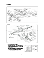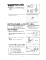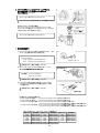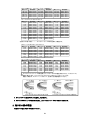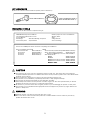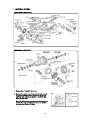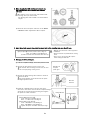
1
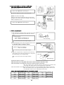
10年09月 M56Y720
INSTALLATION MANUAL
3.692 FINAL GEAR SET for BNR32/BCNR33/BNR34
BNR32/BCNR33/BNR34用 3.692 ファイナルギアセット
品
番
Part Number
適
合
Application
591002
BNR32/BCNR33(アクティブLSD除く)/BNR34(アクティブLSD含む)
BNR32/BCNR33 (excluding models with active LSD) / BNR34 (including models with active LSD)
日本語・・・・・・・・・・・・・・2p
English・・・・・・・・・・・・・・7p
●この取扱説明書を良く読んでからお使いください。
●日産自動車の発行する整備要領書と併せてお使いください。
●取り付け後も大切に保管してください。
●販売店様で取り付けをされる場合は本書を必ずお客様へお渡しください。
TOMEI 製品のお買い上げありがとうございます。
ゲトラグミッション・ホリンジャーなどを搭載した500ps前後の車両にベストマッチのギア比設定。
FSWなどを走行する際、3.545のままでは上は伸びるが、立ち上がりが遅く、結果的にトップスピード
が遅くなってしまいます。3.9や4.1ではすぐに吹け切ってしまい、ストレートでアクセルを踏み抜くこと
ができません。3.692はわずか0.153の違いで、立ち上がりからトップスピードまでスムースに
車速を伸ばすことが可能です。
●
●
●
●
Please carefully read this manual prior to installation.
Please also refer to the Nissan Service Manual with this Manual.
After the installation has been completed please keep this manual for future reference.
If the install was done in a shop please make sure to give this manual to the owner.
Thank you for purchasing a TOMEI product.
This gear setup is best suited for use with the BNR34 Getrag and Holinger transmissions for up to
500HP. When using the 3.545 final gear ration on Fuji Speedway, the acceleration is slow which
results inslower times to reach top speed. Both 3.9 and 4.1 ratios deliver great acceleration but it is
not ideal for the GTR and larger tracks like Fuji Speedway. The difference of 0.153 for the ratio of
3.692 delivers a large change in the cars gearing balance. This best suits both acceleration and top
speed.
1
部品構成
キットに付属されている内容は下記の通りです。( )内は数量です。
フロントドライブピニオン(1)
フロントドライブピニオン(1)
リヤドライブピニオン(1)
取り付けに必要な部品・工具
・整備要領書
・エンジン整備用工具一式
・トルクレンチ
・ダイヤルゲージ
・ネジロック剤
・光明丹
・液体ガスケット
<用意しておくと便利な工具>
・ベアリングプーラー
・ドリフト
・フランジレンチ
・プリロードゲージ
<作業時に交換を推奨する純正部品>
フロント(すべて32˜34共通)
REAR
・ドライブピニオンナット 38216-U301A(1)
・ドライブピニオンナット(32〜34共通)38216-U301A(1)
・ピニオンシール
C8189-03V00(1)
・ピニオンシール(32〜34共通)
38189-N3112(1)
・サイドシール
38342-03V11(1)
※BNR32 〜91.07のみ
8189-21G00(1)
・サイドシール
38342-03V01(1)
・サイドシール
BNR32
38342-N3100(2)
BCNR33
38342-P9000(2)
BNR34標準車99.01〜99.10
38342-P9000(2)
BNR34標準車99.10〜
38342-P9010(2)
BNR34 V-SPEC
38342-15U00(2)
注意
■本品は自動車競技専用部品です。サーキットや公道から閉鎖されたコース内に限って使用してください。
■本品の取り付けは特別の訓練を受けた整備士が、設備の整った作業場で実施してください。
■指定する車種以外への取り付けはおやめください。本品およびエンジンを破損する恐れがあります。
■誤った組み付けや使い方は本品および、周辺装置を破損したり、車両の安全性を損なう原因になり危険です。
■部品脱着の際には無理な力を加えないでください。部品を破損する恐れがあります。
■取り付けの際は、適切な工具、保護具を使用しないと、けがにつながり危険です。
警告
■本品の取り付けは関係部位が冷えた状態で行ってください。
■部品欠落による車輌の破損・火災が起こる可能性があるため、製品構成部品の取り付けは確実に
行ってください。
2
1.取り付け
フロント分解図
リヤ分解図
シム
シム
シム
1. ファイナルドライブからオイルを抜く。
2. キャリヤケースカバーを外し、ベアリンキャップに上下
左右があとで認識できるように合いマーク(ペイント)を
行う。※リヤのみ
背面側
また、デフケースを外す際に、サイドベアリングアウター
レースとアジャストシムの組み合わせが変わらな
いように、背面側、歯面側と分けて管理する。
歯面側
合いマーク(ペイント)
3
3. 取り外したLSD以外を使用する場合は、取り外したデフ
ケースからサイドベアリングを外し、使用する側のデフ
ケースに圧入する。
・組み込むベアリングの背面側、歯面側を」間違えないよ
うに注意する。
・作業にはベアリングプーラーおよび、ドリフトの使用を
推奨します。
※ BNR32/BCNR33の場合はフロントケースにピニオンギア
の逃げ加工を行ってください。
4. ドライブギアボルトにネジロック剤を塗布し、キットのドライブギアをデフケースに装着する。
【Torque Specs】Front: 95˜115N・m (9.5˜11.5kg・m)
リヤ:177˜196N・m (18.0˜20.0kg・m)
※数回に分けて締め付けてください
・装着前にドライブギアは洗浄してください。
・ドライブギアボルトを再使用する場合は
洗浄後、使用してください。
・締め付け時はデフケースをバイス等で
しっかり固定して作業してください。
5. ドライブピニオンギアを交換する。
① コンパニオンフランジを固定し、ピニオンロックナットを
外す。
② キャリアケースからドライブピニオンを外す。
外した際、落下させないように手で支えるなどの注意
をしてください。
落下に注意
③ ピニオンベアリングを外し、キットのドライブピニオンに
装着する。
ピニオンハイトアジャストシムの向きに注意して
ください。
④ ドライブピニオンに付属のコラプシブルスペーサーを装着
し、キャリヤケースに組み、コンパニオンフランジを取り
付ける。この時、ピニオンベアリングのプリロードを確認し
ながらピニオンナットを少しづつ締め付けてください。
【ピニオンベアリングのプリロード】
Front: 0.8˜1.1N・m (0.08˜0.11kg・m)
リヤ :1.1˜1.4N・m (0.11˜0.14kg・m)
【ピニオンナットのTorque Specs範囲】
Front: 170˜200N・m (17.0˜20.0kg・m)
リヤ :186˜294N・m (19.0˜30.0kg・m)
ピニオンナットはトルク範囲内で締付けて下さい。
4
向きに注意
フランジレンチ
プリロードゲージ
6. ファイナルドライブユニットにデフケースとアジャスト
シムを組み込み、ベアリングキャップをつけて
ボルトを締める。※リヤのみ
【Torque Specs】88˜98N・m (9.0˜9.9kg・m)
ベアリングキャップに記した合いマークを確認して下さい。
合いマーク(ペイント)
【BNR34 アクティブLSD車の場合】
サイドベアリングアジャストシムとピストンベアリングを
キャリヤケースに組込み、OリングをアクチュエーターASSY
に取り付け後、ボルトを締めてください。
シム
【Torque Specs】40˜49N・m (4.0˜5.0kg・m)
7. 各部の調整を行う
① コンパニオンフランジを20回以上回転させた後、トータル
プリロードを基準値内であるか測定する。
【Torque Specs】
Front: 0.8˜2.1N・m (0.08˜0.21kg・m)
Rear : 1.5˜2.1N・m (0.15˜0.21kg・m)
プリロードゲージ
基準値を外れた場合は調整してください。
② ダイヤルゲージをドライブギヤの歯に当て、バック
ラッシュが基準値内であるか測定する。
【基準値】
ダイヤルゲージ
Front: 0.10˜0.20mm
Rear : 0.13˜0.18mm
基準値を外れた場合は調整してください。
③ ドライブギアの歯に光明丹を薄く塗り、ドライブギアと
ドライブピニオンを回転させて右図の歯当たりである
ことを確認する。
ドライブ側
バック側
基準値を外れた場合は調整してください。
【基準状態】
〔基準を外れた場合の調整方法〕
・プリロードが大きい場合・・・・・・・
サイドベアリングアジャストシムを左右とも薄くする。
・プリロードが小さい場合・・・・・・・
サイドベアリングアジャストシムを左右とも厚くする。
・バックラッシュが大きい場合・・・・
Front: サイドベアリングアジャストシムを左右とも薄くする
リヤ:サイドベアリングアジャストシムの左側を厚く、右側を左の同量薄くする。
・バックラッシュが小さい場合・・・・
Front: サイドベアリングアジャストシムを左右とも厚くする
リヤ:サイドベアリングアジャストシムの右側を厚く、左側を右の同量薄くする。
フロント右側サイド ベアリング プリロード調整用シム
厚さ(mm)
部品番号
厚さ(mm)
部品番号
0.65
38453-03V66
0.35
38453-03V60
0.70
38453-03V67
0.40
38453-03V61
0.45
0.75
38453-03V68
38453-03V62
38453-03V69
0.50
38453-03V63
0.80
0.85
38453-03V70
0.55
38453-03V64
0.90
38453-03V71
0.60
38453-03V65
5
厚さ(mm)
0.95
1.00
1.05
1.10
1.15
部品番号
38453-03V72
38453-03V73
38453-03V74
38453-03V75
38453-03V76
フロント左側サイド ベアリング プリロード調整用シム
厚さ(mm)
部品番号
厚さ(mm)
部品番号
1.93˜1.97 38453-03V00 2.18˜2.22 38453-03V05
1.98˜2.02 38453-03V01 2.23˜2.27 38453-03V06
2.03˜2.07 38453-03V02 2.28˜2.32 38453-03V07
2.08˜2.12 38453-03V03 2.33˜2.37 38453-03V08
2.13˜2.17 38453-03V04 2.38˜2.42 38453-03V09
リヤ サイドベアリングアジャストシム
厚さ(mm)
部品番号
厚さ(mm)
38453-15U00
1.01
1.37
1.04
38453-15U01
1.40
1.43
1.07
38453-15U02
1.10
38453-15U03
1.46
1.13
38453-15U04
1.49
1.16
38453-15U05
1.52
1.19
38453-15U06
1.55
1.22
38453-15U07
1.58
1.25
38453-15U08
1.61
1.28
38453-15U09
1.64
1.31
38453-15U10
1.67
38453-15U11
1.34
1.70
部品番号
38453-15U12
38453-15U13
38453-15U14
38453-15U15
38453-15U16
38453-15U17
38453-15U18
38453-15U19
38453-15U20
38453-15U21
38453-15U22
38453-15U23
厚さ(mm)
2.43˜2.47
2.48˜2.52
2.53˜2.57
2.58˜2.62
2.63˜2.67
部品番号
38453-03V10
38453-03V11
38453-03V12
38453-03V13
38453-03V14
厚さ(mm)
1.73
1.76
1.79
1.82
1.85
1.88
1.91
1.94
1.97
2.00
部品番号
38453-15U24
38453-15U60
38453-15U61
38453-15U62
38453-15U63
38453-15U64
38453-15U65
38453-15U66
38453-15U67
38453-15U68
・歯当たりが悪い場合・・・・・・・・・・
ピニオンハイトシムの厚さを変えて調整する。
フロント ドライブピニオンアジャストシム
厚さ(mm)
部品番号
厚さ(mm)
3.09
38154-U1500
3.30
3.12
38154-U1501
3.33
3.15
38154-U1502
3.36
3.18
38154-U1503
3.39
3.21
38154-U1504
3.42
3.24
38154-U1505
3.45
3.27
38154-U1506
3.48
部品番号
38154-U1507
38154-U1508
38154-U1509
38154-U1510
38154-U1511
38154-U1512
38154-U1513
厚さ(mm)
3.51
3.54
3.57
3.60
3.63
3.66
部品番号
38154-U1514
38154-U1515
38154-U1516
38154-U1517
38154-U1518
38154-U1519
リヤ ピニオンハイトアジャストシム
厚さ(mm)
部品番号
厚さ(mm)
3.09
38154-P6017
3.30
3.12
38154-P6018
3.33
3.15
38154-P6019
3.36
3.39
3.18
38154-P6020
3.42
3.21
38154-P6021
3.45
3.24
38154-P6022
3.27
38154-P6023
3.48
部品番号
38154-P6024
38154-P6025
38154-P6026
38154-P6027
38154-P6028
38154-P6029
38154-P6030
厚さ(mm)
3.51
3.54
3.57
3.60
3.63
3.66
部品番号
38154-P6031
38154-P6032
38154-P6033
38154-P6034
38154-P6035
38154-P6036
ピニオンハイトワッシャーの厚さを変えて、ピニオンギアの位置を変化させると、バックラッシュも
同時に変化します。サイドベアリングアジャストシムおよび、ピニオンハイトシムを
調整した場合は、プリロード、バックラッシュ、歯当たりを再度確認してください。
ヒール当たり
フェース当たり
ドライブピニオンをリングギアに近づける
トー当たり
フランク当たり
ドライブピニオンをリングギアから遠ざける
8. キャリアカバーに液体ガスケットを塗布し、取り付ける。
9. ファイナルドライブユニットを車両に復帰し、LSDオイルをフィラープラグの高さまで充填する。
2.取り付け後の確認
各部にオイル漏れが無いか確認してください。
6
KIT CONTENTS
Below is the contents of this kit with the quantity listed in brackets ().
FRONT DRIVE PINION (1)
FRONT CROWN RING GEAR (1)
REAR CROWN RING GEAR (1)
REQUIRED TOOLS
These tools are the bare minimum required for the job.
・NISSAN Workshop Service Manual
・General Engine Maintenance Tools
・Torque Wrench
・Dial Gauge
・Red Gear Marking Compound
・Thread lock paste ・Liquid Gasket
<Please prepare for ease of installation>
・Bearing Puller
・Drift
・Flange Wrench
・Pre Load Gauge
<These stock OEM parts will be needed for completing the installation>
Front (Compatible with 32˜34)
REAR
・Drive Pinion Nut
38216-U301A(1)
・Drive Pinion Nut (32˜34 Compatible)38216-U301A(1)
・Pinion Seal
C8189-03V00(1)
・Pinion Seal (32˜34 compatible)
38189-N3112(1)
・Side Seal.
38342-03V11(1)
※Only for BNR32 up to '91/07 8189-21G00(1)
・Side Seal
38342-03V01(1)
・Side Seal Part No.
BNR32
38342-N3100(2)
BCNR33
38342-P9000(2)
BNR34 99 Jan˜99 Oct models 38342-P9000(2)
BNR34 99.10 onwards models 38342-P9010(2)
BNR34 V-SPEC
38342-15U00(2)
CAUTION
■ This manual is only to be used as a supplement reference guide only. This manual does not provide the
complete installation procedure. For detailed instructions on the procedure, please refer to the official Nissan
workshop service manual.
■ These products are designed to be used for off road competition purposes only.
■ This product is to be installed by a qualified professional in a fully equipped workshop.
■ This product was designed specifically for the application specified.
■ If the attempt was made to use this product on another engine/car other than specified then you will risk
damaging this kit and or the engine or components related with it.
■ Do not use any excessive force when using this product as you risk damaging the product or other parts.
■ This product is to be installed with the appropriate tools and equipment to prevent any engine failures and
injuries or bodily harm.
WARNING
■ Install the product only when the engine & drive train is cold.
■ Due to the nature of the area where the product's) is installed. Please exercise caution to prevent any
possible fire hazards from oil etc.
7
1. INSTALLATION
FRONT SIDE ILLUSTRATION
REAR SIDE ILLUSTRATION
1. Remove the oil from the final drive.
2. Remove the carrier case, then mark the bearing caps
so you can tell which is the correct one for up and
left from right. A paint pen marker is useful for this.
※For the rear only.
Rear Side
Once the diff case has been removed, make sure that
the side bearings and adjustment shims are marked
and separated. Do not mix them.
Flank Side
Mark (Point)
8
3. When changing the LSD, you'll need to remove the
side bearings, than have it pressed onto the new
LSD case.
・Be cautious not to mix the rear side and flank side
bearings when you do the install.
・The bearing puller tool and drift is recommended for
the job.
※ Check the front case pinion clearance on the BNR32
& BCNR33 models. Adjustments will be required.
4. Apply thread lock paste to the crown ring gears bolts before installing them onto the diff case.
【Torque Specs】Front: 95˜115 N・m (9.5˜11.5kg・m)
Rear: 177˜196N・m (18.0˜20.0kg・m)
※ Check several times the bolts when done up
・Wash & clean the drive crown ring before
installation.
・Clean and check any bolts before reusing
them.
・Use a vice to secure the diff in place
when sealing the diff case.
5. Changing the drive pinion gear.
① Lock the companion flange, remove the pinion lock nut.
② Remove the drive pinion from the carrier case.
Be cautious when removing from the case, be sure
not to drop anything on the ground.
Note:Do not
drop the
pinion gear.
③ Remove the pinion bearing, then install it to the drive
pinion from the kit.
Pay close attention to the direction of the pinion
height adjustment shim.
④ Install the collapsible spacer onto the drive pinion,
then fit it to the carrier case and fit the companion flange.
Verify the pre-load of the pinion bearing, then tighten
the pinion nut a little each time.
【Pinion Bearings Pre Load】
Front: 0.8˜1.1N・m (0.08˜0.11kg・m)
Rear : 1.1˜1.4N・m (0.11˜0.14kg・m)
【Pinion Nut Torque Specs】
Front: 170˜200N・m (17.0˜20.0kg・m)
Rear : 186˜294N・m (19.0˜30.0kg・m)
Tighten the pinion nut within the torque range.
9
Note the
direction
Flange Wrench
Pre Load Gauge
6. Install the final drive and LSD into the differential
case, fit the bearing caps and tighten the bolts.
※ For the rear only.
【Torque Specs】88˜98N・m (9.0˜9.9kg・m)
Check the alignment marks on the bearing cap.
Marking (Point)
【BNR34 cars with active LSD】
Install the side bearings adjustment shims and the piston
bearing into the carrier case. Fit the O-Ring in the actuator
ASSY and tighten the bolts.
【Torque Specs】40˜49N・m (4.0˜5.0kg・m)
7. PARTS ADJUSTMENTS
① After turning the companion flange around for at least 20
times, the total preload will be set within the required
level.
【Torque Specs】
Front: 0.8˜2.1N・m (0.08˜0.21kg・m)
Rear : 1.5˜2.1N・m (0.15˜0.21kg・m)
Pre Load Gauge
If it comes off, you'll need to adjust it again.
② Fit the dial gauge to the crown ring gears teeth to check
the backlash. Adjust accordingly if required.
Dial Gauge
【Reference】Front: 0.10˜0.20mm
Rear : 0.13˜0.18mm
If it comes off, you'll need to adjust it again.
③ Apply the red gear marker compound to the crown ring
gears teeth, turn the drive gear and pinion to verify that
the tooth bearing is in the right setting.
Drive Side
Back Side
If it comes off, you'll need to adjust it again.
【Ideal Setting】
〔Adjustment Reference Guide〕
・When the preload is too large:Adjust either/both the side bearing shims with thinner shims.
・When the preload is too small:Adjust either/both the side bearing shims with thicker shims.
・When the backlash is too large:Front: Use thinner side bearing shims on both sides.
Rear: Use a thicker shim on the left side of the side bearing, and a thinner shim
on the right side. Always make the same adjustments to both sides.
・When the backlash is too small:
Front: Change the thickness on the side bearing flanges shims on both sides.
Rear: Use a thicker shim on the right side bearing, then a thinner shim on the
left side.Always make the same adjustments to both sides.
FRONT RIGHT SIDE BEARING PRELOAD ADJUSTMENT SHIMS
Part No.
Thickness (mm)
Part No.
Thickness (mm)
0.35
38453-03V60
0.65
38453-03V66
0.40
38453-03V67
38453-03V61
0.70
0.45
38453-03V62
0.75
38453-03V68
38453-03V69
0.50
38453-03V63
0.80
0.55
38453-03V64
0.85
38453-03V70
38453-03V65
0.90
38453-03V71
0.60
10
Thickness (mm)
0.95
1.00
1.05
1.10
1.15
Part No.
38453-03V72
38453-03V73
38453-03V74
38453-03V75
38453-03V76
FRONT LEFT SIDE BEARING PRELOAD ADJUSTMENT SHIMS
Part No.
Part No.
Thickness (mm)
Thickness (mm)
1.93˜1.97
2.18˜2.22
38453-03V05
38453-03V00
1.98˜2.02
2.23˜2.27
38453-03V06
38453-03V01
2.03˜2.07
2.28˜2.32
38453-03V02
38453-03V07
2.33˜2.37
2.08˜2.12
38453-03V03
38453-03V08
2.38˜2.42
2.13˜2.17
38453-03V04
38453-03V09
REAR SIDE ADJUSTMENT BEARING SHIMS
Thickness (mm)
Thickness (mm)
Part No.
1.37
1.01
38453-15U00
1.40
1.04
38453-15U01
1.43
1.07
38453-15U02
1.10
38453-15U03
1.46
1.13
38453-15U04
1.49
1.16
38453-15U05
1.52
1.19
38453-15U06
1.55
1.22
38453-15U07
1.58
1.25
1.61
38453-15U08
1.28
38453-15U09
1.64
1.31
38453-15U10
1.67
1.34
38453-15U11
1.70
Part No.
38453-15U12
38453-15U13
38453-15U14
38453-15U15
38453-15U16
38453-15U17
38453-15U18
38453-15U19
38453-15U20
38453-15U21
38453-15U22
38453-15U23
Thickness (mm)
2.43˜2.47
2.48˜2.52
2.53˜2.57
2.58˜2.62
2.63˜2.67
Part No.
38453-03V10
38453-03V11
38453-03V12
38453-03V13
38453-03V14
Thickness (mm)
1.73
1.76
1.79
1.82
1.85
1.88
1.91
1.94
1.97
2.00
Part No.
38453-15U24
38453-15U60
38453-15U61
38453-15U62
38453-15U63
38453-15U64
38453-15U65
38453-15U66
38453-15U67
38453-15U68
・Verify the tooth contact pattern……Adjust the thickness of the pinion shim height.
FRONT Drive Pinion Adjust Shims
Thickness (mm)
Part No.
Thickness (mm)
3.09
38154-U1500
3.30
3.12
38154-U1501
3.33
3.15
38154-U1502
3.36
3.18
38154-U1503
3.39
3.21
38154-U1504
3.42
3.24
38154-U1505
3.45
3.27
38154-U1506
3.48
REAR PINION
Thickness (mm)
3.09
3.12
3.15
3.18
3.21
3.24
3.27
HEIGHT ADJUSTMENT SHIMS
Part No.
Thickness (mm)
38154-P6017
3.30
38154-P6018
3.33
38154-P6019
3.36
38154-P6020
3.39
38154-P6021
3.42
38154-P6022
3.45
38154-P6023
3.48
Part No.
38154-U1507
38154-U1508
38154-U1509
38154-U1510
38154-U1511
38154-U1512
38154-U1513
Thickness (mm)
3.51
3.54
3.57
3.60
3.63
3.66
Part No.
38154-U1514
38154-U1515
38154-U1516
38154-U1517
38154-U1518
38154-U1519
Part No.
38154-P6024
38154-P6025
38154-P6026
38154-P6027
38154-P6028
38154-P6029
38154-P6030
Thickness (mm)
3.51
3.54
3.57
3.60
3.63
3.66
Part No.
38154-P6031
38154-P6032
38154-P6033
38154-P6034
38154-P6035
38154-P6036
Chang the pinion height washer thickness to change the pinion position, will also change the backlash
setting as well. When you adjust the side bearing shims & pinion height adjustment washers, for setting the
preload and backlash please also check the gearing teeth alignment again.
Heel Contact Point
Face Contact Point Toe Contact Point
The Drive Pinion is brought closer to the ring
Flank Contact Point
Crown ring & Pinion Gear is further apart.
8. Apply the liquid silicon gasket to the carrier cover before sealing it.
9. Fit the final drive assembly to the vehicle and fill with the appropriate LSD differential gear oil,
up to the filler plug.
2. INSTALLATION VERIFICATION
Please verify that there are no signs of oil leaks from the diff housing and or car.
11
株式会社 東名パワード
〒194-0004 東京都町田市鶴間1737−3
TEL : 042−795−8411(代)
FAX : 042−799−7851
1737-3 Tsuruma Machida-shi Tokyo 194-0004 JAPAN
TEL : +81-42-795-8411(main switchboard)
http://www.tomei-p.co.jp
この製品に関わる取り付け、操作上のご相談は上記へお願いします。
営業時間:月〜金(祝祭日、年末年始を除く)9:00〜18:00
If you have any questions in regards to the installation of this product,
please contact your local authorized Tomei Powered distributor.
OPEN: Monday - Friday (National holidays and public holidays excluded). 09:00 - 18:00
10年09月 3.692ファイナルギアセット 取扱説明書 M56Y720
2010 Sep. : 3.692 Final Gear Installation Manual M56Y720
12