1
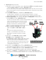
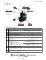
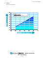
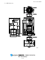
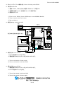
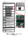
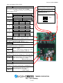
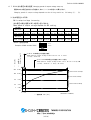
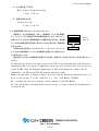
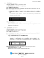
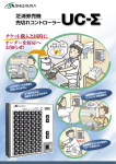
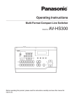
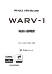
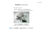
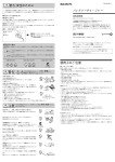
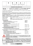
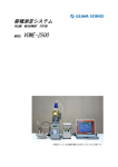
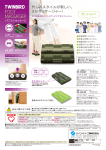
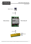
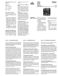
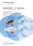
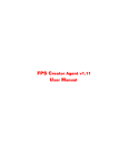
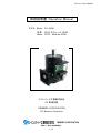
Ref. No. SCDD-090009
取扱説明書 Operation Manual
モデル Model: SC-UD08
名称: FPSC モジュール UD08
Name: FPSC Module UD08
ツインバード工業株式会社
SC 事業本部
TWINBIRD CORPORATION
SC Business Operation
TWINBIRD CORPORATION
http://fpsc.twinbird.jp
(1/19)
Ref. No. SCDD-090009
1. 適用分野と輸出規制について
Field of Application and Restriction of Export
TWINBIRD CORPORATION
http://fpsc.twinbird.jp
(2/19)
Ref. No. SCDD-090009
輸出規制について
スターリング冷凍機は以下の日本の輸出規制と米国の再輸出規制が適用されます。
日本から輸出される場合は、経済産業大臣の許可が必要となります。
この場合は、米国の再輸出規制は適用除外になります。
輸出先から再輸出する際は、その国の輸出規制に従って下さい。
該当項目:「光検出器の冷却器」
<貨物>
輸出令別表1:10 項(2)号
貨物等省令:第9条1項六号ロ(一)
USA REEXPORT CONTROL, CCL; ECCN 6A002 d.2.a
"Cryocoolers for Optical sensors"
もし、輸出を希望する場合は、事前に弊社SC事業部にお問い合わせください。
なお、この適用は 2008 年 1 月現在であり、法令は改正されることがあります。
The following regulations shall apply to Stirling Cooler and permission for export by the Ministry
of Economy, Trade and Industry is required before exporting Stirling coolers from Japan for
abroad.
・Foreign Exchange and Foreign Trade Law-section 1 of article 48.
・Foreign Exchange and Foreign Trade Law-section 1 of article 67.
・Export Trade Control Ordinance-section 2 of article 8.
If you wish to export our Products from Japan for abroad, please contact us prior to exporting.
The above regulations were applied at the time of January 2008. Laws and regulations may be
revised according to the legal revisions.
TWINBIRD CORPORATION
http://fpsc.twinbird.jp
(3/19)
Ref. No. SCDD-090009
2. 警告及び注意 Warning and Caution
(1) FPSC モジュール(Free Piston Stirling Cooler Module)は DC24V 専用です。DC12V あるいは AC100
~240V 等、他の電圧では使用しないでください。故障の原因となります。
The Free Piston Stirling Cooler Module (FPSC Module) must be used with a 24 V DC power
source. Internal damage can result from operating this FPSC Module directly with any input voltage
other than 24 V DC.
(2) 0~35℃の環境でご使用ください。これ以外ですと、故障の原因となります。
The FPSC Module is designed for use in ambient temperatures between 0 - 35 deg. C.
Internal damage could result from operating the FPSC Module outside this temperature range.
(3) 吸熱部の許容温度範囲は-100~-20℃です。冷えすぎないよう吸熱量を調節してください。また、ヒー
ターなどで加熱しないで下さい。故障の原因となります。
The cold side of the FPSC Module should be maintained between -100 and -20 deg. C. Operation
吸熱部
outside of this temperature range could result in internal
Cold Side
damage to the FPSC Module. To avoid the possibility of
放熱フィン
damaging to internal parts by overheating the FPSC
Heat Reject Fin
駆動基板
Drive
PCB
Module, do not apply heating elements directly to the cold side.
(4) 放熱フィンをお取り扱いの際は事故やけがにご注意
ください。また、放熱フィンの変形、破損にご注意くだ
さい。
Use caution when handling the Heat Reject Fin
assembly to preventdamage or injury. Inspect the
Heat Reject Fin assembly for deformity or breakage
before use.
(5) FPSC モジュールから異音が発生したときは、出力設定
電圧を調整して FPSC への出力を抑えてください。
それでも異音が発生する場合は、弊社までお問い合わせください。
Reduce the output setting of the FPSC Module if unusual
noises are observed coming from inside the pressure vessel.
Please contact Twinbird if the reduced output setting does
SC-UD08 80W 型 FPSC モジュール
SC-UD08 80W FPSC Module
not eliminate the unusual noises.
(6) FPSC モジュールに強い衝撃を与えないで下さい。故障の原因となります。
Avoid subjecting the FPSC Module to excessive shock. It could cause internal damage.
(7) FPSC モジュールや基板に水をかけないでください。故障の原因となります。
Direct exposure of the FPSC Module and PCB to water could cause electrical failure.
(8) FPSC モジュールや基板をストーブや火気の近くに近づけないで下さい。故障の原因となります。
Direct exposure of the FPSC Module and PCB to fire or excessive heat could cause internal
damage.
TWINBIRD CORPORATION
http://fpsc.twinbird.jp
(4/19)
Ref. No. SCDD-090009
(9) FPSC モジュールを火の中に放り込まないで下さい。内部のガスが膨張し、爆発する恐れがあります。
Warning: Placing the FPSC Module into fire or excessive heat could cause expansion of the
contained gas and explosion.
(10)コードを強く引っ張らないで下さい。断線し、故障の原因となります。
Do not put excessive strain on the electrical cords. It could cause damage to the wire and cause
the FPSC Module stop operating.
(11)FPSC モジュールの放熱フィンや基板の部品は、運転中及び停止直後は高温になっていることがあり
ます。素手で触わらないでください。火傷の恐れがあります。
To avoid the danger of burns, avoid touching the heat reject fin and certain parts on PCB with your
bare hands during or immediately after operation.
(12)FPSC モジュールの吸熱部及びその周辺は、運転中及び停止直後は低温になっています。素手で触
わらないでください。凍傷の恐れがあります。
To avoid the danger of frostbite, avoid touching the cold side and its immediate surroundings with
your bare hands during or immediately after operation.
(13)FPSC モジュールの吸熱部及びその周辺は、霜や露がつかないように断熱してください。また、単体で
の動作確認などで霜や露が付着した場合は、運転を停止させた後にやわらかい布などでふき取ってく
ださい。着霜や結露は冷却能力の低下につながり、融けた霜や露が電源コードや内部の機構部品に
流れ落ちると、電気回路がショートして故障したり、腐食の原因になったりしますので、十分ご注意くだ
さい。
Please provide thermal insulation around cold side to prevent frost and dew condensation. If
conditions require that you need to operate the FPSC Module without thermal insulation, the cold
side may develop a coating frost or water. If this occurs, please clean the cold side with a soft cloth.
Having frost or condensation on the cold side surface can cause an apparent reduction of cooling
capacity. Also, if water drips down on a power cord or inner mechanical parts as it defrosts, it
could cause a short circuit or corrosion.
(14)FPSC モジュールの吸熱部は薄いステンレス板で形成されており、内部は精密構造になっております
ので、熱交換器の取り付けの際など、吸熱部に強い力を加えないで下さい。故障の原因となります。
Failure of the FPSC Module could result from subjecting the cold side to a strong force. It is made
of thin stainless steel sheet surrounding a precision structure.
(15)FPSC 内部に高圧のガスが封入されていますので、廃棄の際は弊社までご相談ください。
The Stirling cooler uses a high pressure gas inside, please contact Twinbird if you intend to scrap
the Stirling cooler.
TWINBIRD CORPORATION
http://fpsc.twinbird.jp
(5/19)
Ref. No. SCDD-090009
3. 仕様 Specification
3.1 外観 Exterior
吸熱部
排熱部サーミスタ
Cold Side
Warm Side Thermistor
放熱フィン
排熱部 Warm Side
Heat Reject Fin
(放熱フィンの接している部分)
(The part which heat reject
fin is attached)
ファン
Fan
FPSCモジュール
駆動基板
Drive PCB
FPSC Module
3.2 主な仕様 Main Specification
No.
1
2
3
4
5
6
7
8
9
10
11
項 目 Item
製品寸法 Product Dimension
製品質量 Weight
冷媒 Refrigerant
冷媒量 Amount of Refrigerant
冷媒圧力
Inside Pressure of Stirling Cooler
電源電圧
Power Source Voltage
最大消費電流
Maximum Current
冷却性能 Cooling Capacity
[条件 Condition]
周囲温度 Ambient Temp.: 25℃
(排熱部温度 Warm Side Temp.: 45℃)
出力設定電圧 Input Voltage to Set Output Voltage: 5V
仕 様 Specification
約(Approximately) W 175 x D 195 x H 290 mm
約(Approximately) 3.5 kg
ヘリウム(He) Helium
3.0 g
3.0 MPa
DC 24 V ±10 % for Drive PCB
6A (RMS)
(24V 入力時, at 24 V Input)
65
+10
-5
W
(吸熱部温度 Cold Side Temp.: -23.3℃)
30
+10
-5
W
(吸熱部温度 Cold Side Temp.: -80℃)
使用温度範囲
Ambient Temperature Range to Use
吸熱部許容温度範囲
Acceptable Temperature Range at
Cold Side
付属品(取付済み)
0 ~ 35 ℃
-100 ~ -20 ℃
駆動基板 (Drive PCB)
Accessories(attached on FPSC module)
TWINBIRD CORPORATION
http://fpsc.twinbird.jp
(6/19)
Ref. No. SCDD-090009
3.3 冷却特性
Graph of Cooling Capacity
80
試験条件 Condition
冷却性能 Cooling Capacity [W]
70
周囲温度 Ambient Temperature: 25℃
60
50
40
30
20
10
0
-120
-100
-80
-60
-40
吸熱部温度 Cold Side Temperature
-20
[℃]
TWINBIRD CORPORATION
http://fpsc.twinbird.jp
(7/19)
0
Ref. No. SCDD-090009
3.4 主要寸法 Main Size
Reje ct F in
放熱フィ ン
(A lum inum )
Ther mist or
サ ーミス タ
175
195
(72)
(12 1)
φ14 0
112
φ37. 7±0. 1
Co ld S ide
7+0
-0 .1
吸熱 部
SU S304
16±0 .5
74
103
PP
23.5
93
84
60
Fan Mot or
4 H alls
t o f ix m odul e
by scr ew
ファ ンモー タ
設置用 ねじ穴( 4ヶ所)
(5 5)
φ 3 .4
13
110
40
55
118
20
32
30
P CB
61 .2
11 8
1 45
234
2 88
6
[mm]
TWINBIRD CORPORATION
http://fpsc.twinbird.jp
(8/19)
Ref. No. SCDD-090009
4.スターリングクーラーの動作方法 Drive of Stirling cooler(FPSC)
4.1準備 Preparation
(1)電源:DC24V、150W 出力(出力電流:平均 6A、ピーク電流 9A)
(2)温調器と温度センサー(抵抗器でマニュアル動作可能)
(3)配線材とスイッチ
(1)Power source: DC24V, Output 150W(Output current:6A(RMS), Max.9A)
(2)Temp. controller and Temp. sensor
(3)Wire and Switch
4.2配線 Wiring of the Drive PCB
温調器
Tem p.C ont rol ler
温 度センサ ー
Te mp.Sen sor
スイ ッチ
Swit ch
ス イッチ
Sw itc h
123456789
+
-
-
+
CN6
※ 電流制御 (4 ~20mA)
Cu rre nt Con tro l(4 ~20 mA)
CN7
-
CN2
DC 24V Ma x.5 00mA
CN8
電圧制御と電流制御を選択します。
CN7
+
サー ミス タ
Th ermist or
123456789
電圧制御( 1~5 V) ※
V oltage Co ntrol( 1~5 V)※
-
フ ァンモータ
Fan Motor
+
CN1
DC24V 電源
DC2 4V Pow er Supply
通 常6 A
ピーク 電流 :M ax9A
(極性なし)
+ -
4.3運転方法 Drive of FPSC
(1)DC24V 電源のスイッチを入れる。
(2)駆動基板に取り付けたスイッチを ON(CLOSE)にする。
(1)Turn on the Switch of Power supply.
(2)Turn on the Switch of the Drive PCB.
4.4停止方法 Stop of FPSC
(1)駆動基板に取り付けたスイッチを OFF(OPEN)にする。
(2)DC24V 電源のスイッチを切る。
(1)Turn off the Switch of the Drive PCB.
(2)Turn off the Switch of Power supply.
TWINBIRD CORPORATION
http://fpsc.twinbird.jp
(9/19)
Ref. No. SCDD-090009
5. 駆動基板の入出力
Pin
仕 様
[CN7]フェニックスコンタクト MPT0.5/9-2.54
・適合電線: 0.14 ~ 0.5 mm2(より線・単線)
26 ~ 20 AWG
・電線むき長さ: 4.5 mm
1
2(+)
3(-)
4
出力設定入力 1
入力
DC 1.0~5.0 V
出力(CN8) AC 2.0~16 V
出力設定入力 2
入力
DC 4~20 mA
出力(CN8) AC 2.0~16 V
運転/停止信号入力
入力
High Low
機能
停止 運転
異常信号出力
[SW1] DIP SW
電圧上昇速度設定
[SW2] DIP SW
排熱部温度上限設定
[SW3] DIP SW
電流制限値設定
DIP SW と設定値の例
ON
・・・ ON (1)
・・・ OFF (0)
1
2
3
4
0
0
0
1
5
出力
High Low
状態
異常 正常
警告信号出力 1
6
出力
High Low
状態
警告 正常
警告信号出力 2
7
出力
High Low
状態
警告 正常
8(0V) リファレンス出力
・出力電圧: DC 5.0 V (±10%)
9(+5V) ・許容出力電流: 50 mA
[CN2] JST B2B-PH-K-E (青)
・適合コネクタ: JST PHR-2
1
排熱部サーミスタ
2
[CN6] JST B2B-PH-K-S (白)
・適合コネクタ: JST PHR-2
ファン出力
1(+)
・出力電圧: 電源入力電圧 +0/-0.3 V
2(-)
・許容出力電流: 500 mA
[CN8] IDEC BP100-2PN10
・端子ねじ: M3.5
・適正締付トルク: 0.6~1.0 N・m (6.1~10.2 kgf・cm)
FPSC 出力
1
・出力電圧範囲: AC 2.0~16 V (RMS)
・許容出力電流: 9 A (RMS)
2
(設定最大値)
[FG] φ 1.8 mm (穴)
GND
[CN1] IDEC BP100-2PN10
・端子ねじ: M3.5
・適正締付トルク: 0.6~1.0 N・m (6.1~10.2 kgf・cm)
電源入力
1(+)
・入力電圧: DC 24 V (±10%)
・最大消費電流: 6 A (RMS)
2(-)
(24V 入力時)
TWINBIRD CORPORATION
http://fpsc.twinbird.jp
(10/19)
Ref. No. SCDD-090009
Input and Output of Drive PCB
Pin
Specification
[CN7] PHOENIX CONTACT MPT0.5/9-2.54
Acceptable Wire: 0.14 - 0.5 mm2, 26 - 20 AWG
(Stranded conductor, Solid conductor)
Strip Length: 4.5 mm
1
2(+)
3(-)
4
Setting of Output 1
Input
1.0 ~ 5.0 V DC
Output (CN8)
2.0 ~ 16 V AC
Setting of output 2
Input
4 ~ 20 mA DC
Output (CN8)
2.0 ~ 16 V AC
Drive / Stop of FPSC
Input
High
Low
Function
Stop
Drive
[SW1] DIP SW
Setting of Output Voltage Change
[SW2] DIP SW
Setting of Warm Side Temperature Limit
[SW3] DIP SW
Setting of Output Current Limit
Example of DIP SW and the Value
ON
・・・ ON (1)
・・・ OFF (0)
1
2
3
4
0
0
0
1
5
Output
High
Low
Status
Emergency Normal
Alarm Signal 1 Output
6
Output
High
Low
Status
Alarm
Normal
Alarm Signal 2 Output
7
Output
High
Low
Status
Alarm
Normal
Reference
Voltage
Output
8(0V)
Output Voltage: 5.0 V DC (±10%)
9(+5V) Output Current Capacity: 50 mA
[CN2] JST B2B-PH-K-E (Blue)
Acceptable Connector: JST PHR-2
1
Warm Side Thermistor
2
[CN6] JST B2B-PH-K-S (White)
Acceptable Connector: JST PHR-2
Output to Fan
1(+)
Output Voltage:
Power Source Voltage +0/-0.3 V
2(-)
Output Current Capacity: 500 mA
[CN8] IDEC BP100-2PN10
- Screw: M3.5
- Proper Torque: 0.6~1.0 N m (6.1~10.2 kgf cm)
Output to FPSC
1
Output Voltage Range: 2.0~16 V AC (RMS)
Output Current Capacity: 9 A (RMS)
2
(Maximum value to set)
[FG] φ 1.8 mm (Hole)
GND
[CN1] IDEC BP100-2PN10
- Screw: M3.5
- Proper Torque: 0.6~1.0 N m (6.1~10.2 kgf cm)
Power Source Input
1(+)
Input Voltage: 24 V DC (± 10 %)
Maximum Current: 6 A (RMS)
2(-)
(at 24 V Input)
TWINBIRD CORPORATION
http://fpsc.twinbird.jp
(11/19)
Ref. No. SCDD-090009
6.駆動基板の動作 Function of Drive PCB
6.1 動作概要 Outline of Function
この基板は、80W 型フリーピストンスターリングクーラー(FPSC)を接続し、下記の機能を有します。
This PCB is designed to operate in conjunction with a 80W Free Piston Stirling Cooler (FPSC) and has the
following functions.
(1) DC24V を電源入力とし、80 Hz の PWM 波形を出力することで FPSC を駆動します。
To drive FPSC with 80 Hz PWM output, with power inverted from 24 V DC input power.
(2) FPSC の駆動電圧は、所定の端子に電圧(DC 1~5V)又は、電流(DC 4~20mA)を入力することにより
決定されます。
To provide the desired drive voltage to the FPSC, the drive voltage is decided by the input
voltage (1- 5 V DC) or input current (4 - 20 mA DC) to the control terminal.
(3) FPSC 運転開始直後において、FPSC の駆動電圧は DIP SW で設定された速度で段階的に上昇しま
す。
After initial start up of the FPSC, the driving voltage increases in steps at a speed determined by
the DIP switch settings.
(4) FPSC への出力電流が DIP SW で設定された値を超えないよう、出力電圧を制限します。
Control the output voltage in order to limit the output current to the FPSC not to exceed the
value set by the DIP switch.
(5) FPSC が動作中に、ファンモーターへ電圧を供給します。
While FPSC is working, it provides voltage supply to the fan motor.
(6) 次の状態検出時に、所定の端子より異常信号を出力し、FPSC の動作を停止します。
The PCB outputs an emergency signal and stops power output to the FPSC when following
conditions are detected
①排熱側温度センサーの温度が、DIP SW で設定された温度に達した。
When the temperature of the sensor on the warm side reaches the temperature set by the
DIP switch.
②FPSC が接続されていないか、又は、断線した。
When the FPSC is disconnected or the input power wire is cut.
③温度センサーが接続されていないか、又は、断線した。
When the temperature sensor is disconnected or wire is cut.
④入力電源電圧が範囲外である。
The power source voltage is out of allowable range.
TWINBIRD CORPORATION
http://fpsc.twinbird.jp
(12/19)
Ref. No. SCDD-090009
(7) 次の状態検出時に、所定の端子より警告信号を出力します。
Generating an alarm signal from prescribed terminal when the following conditions are
detected.
①排熱部に設置した温度センサーの温度が、DIP SW で設定された温度よりも 5℃低い温度に
達した。
When the temperature of the sensor on the warm side reaches 5 deg C lower than the
temperature setting of the DIP switch.
②FPSC への出力設定信号のレベルが規定の範囲外である。
When the level of output set signal is out of the allowed range.
6.2 電源 Power source
電源入力端子(CN1)に電源を接続します。
Connect power source to power input terminal (CN1).
No.
項 目 Item
1 定格電圧
Rating voltage
2 許容電圧範囲
Allowable voltage
3 最大入力電流
Maximum input current
仕 様 Specification
DC 24 V
DC 21.6 ~ 26.4 V (DC 24 V ± 10 %)
6A (RMS)(24V 入力時)
(at 24 V of input voltage)
6.3 FPSC への出力 Output to FPSC
FPSC 出力端子(CN8)より、FPSC へ駆動電圧を出力します。
Drive voltage to FPSC is supplied from FPSC output terminal (CN8).
No.
項 目 Item
1 出力波形
Output wave shape
2 基本周波数
Frequency
3 キャリア周波数
Carrier frequency
4 出力電圧範囲
Output voltage range
5 最大出力電流
Output current capacity
仕 様 Specification
PWM 波形
PWM
80.0Hz
28.8 kHz
AC 2.0~16.0 V (RMS) @80.0Hz
9A (RMS)
TWINBIRD CORPORATION
http://fpsc.twinbird.jp
(13/19)
Ref. No. SCDD-090009
6.4 ファン出力 Output to fan
ファン出力端子(CN6)より、ファンへ電圧を出力します。
Drive voltage to fan is supplied from fan output terminal (CN6).
No.
項 目 Item
1 出力条件
Condition for output
2 出力電圧
Output voltage
3 最大出力電流
Output current capacity
仕 様 Specification
FPSC 駆動時
While FPSC is driven
電源入力電圧 +0/-0.3 V
Power source voltage +0/-0.3 V
500 mA
6.5 FPSC の運転/停止 Drive / stop of FPSC
運転/停止信号入力端子(CN7-#4)の状態に応じ、FPSC へ電圧出力/停止を行います。
FPSC is driven or stopped by drive / stop signal at signal input terminal (CN7-#4).
No.
入力信号
Input
High
(Open)
機 能
Function
停止(FPSC への電圧出力停止)
1
Stop
運転(FPSC へ電圧出力)
2
Low
Drive
* High=DC 5V,Low=GND
* 入力端子は、基板内で 47kΩ抵抗にて DC 5V に接続
Signal input terminal is connected to 5V DC through 47 k ohm resistor on PCB.
6.6 出力設定 Setting of output
出力設定入力(電圧入力=CN7,Pin#1 又は電流入力=CN7,Pin#2,3 のどちらか一方)の値によって、FPSC
へ出力する電圧を決定します。
Output voltage is decided by input voltage (CN7, Pin # 1) or input current (CN7, Pin # 2, 3).
入力無効
Out of
input range
Step No.
電圧
Voltage (V)
[V]
電流
Current (I)
[mA]
0.000≦V<1.000
0.000≦I<4.000
入力無効
Out of
input range
入力有効範囲
Available input range
1
・・・
65
・・・
129
・・・
256
1.000
・・・
2.004
・・・
3.008
・・・
5.000
・・・
20.000
4/255 (V/Step)
4.000
・・・
8.016
・・・
12.031
5.000<V<6.000
20.000<I<21.000
16/255 (mA/Step)
出力電圧
2.000 ・・・ 8.300 ・・・ 12.500 ・・・ 16.000
Output
2.000
voltage
0.25×14/127
0.45×14/64
0.3×14/64
[V]
(V/Step)
(V/Step)
(V/Step)
* 電圧および電流が同時入力されている場合は、電圧入力が優先されます。
Input voltage has priority over input current.
TWINBIRD CORPORATION
http://fpsc.twinbird.jp
(14/19)
16.000
Ref. No. SCDD-090009
6.7 FPSC 出力電圧の変化速度 Changing speed of output voltage ramp-up
運転時の出力電圧を変化させる速度は、次の(1)~(3)の状態により異なります。
Changing speed of output voltage depends on the driving condition, following (1) –
(3).
(1)出力電圧を上げる時
While output voltage increasing
出力電圧の変化速度は SW1 の設定に基づきます。
Ramp speed of output voltage depends on SW1 setting.
SW1 状態
SW1 value
Ramp speed of
output voltage
SW1 状態
SW1 value
Ramp speed of
output voltage
0000
0001
0010
0011
0100
0101
0110
0111
1 step /
0.44 sec
1 step /
0.8 sec
1 step /
1.24 sec
1 step /
1.6 sec
1 step /
2.4 sec
1 step /
3.2 sec
1 step /
4.0 sec
1 step /
4.8 sec
1000
1001
1010
1011
1100
1101
1110
1111
1 step /
5.6 sec
1 step /
6.4 sec
1 step /
8.0 sec
1 step /
10.4 sec
1 step /
12.8 sec
1 step /
16.0 sec
1 step /
19.2 sec
1 step /
22.4 sec
※SW1 と設定値の例
ON
→ 出力電圧
Output voltage [V]
→
Step No.
Example of SW1 and the Value
・・・ ON (1)
・・・ OFF (0)
1
2
3
4
0
0
0
1
・2.0V~4.1V 間の電圧上昇速度は固定
Ramp speed of output voltage from 2.0 V to 4.1 V is fixed.
(1 step / 0.44 sec)
・4.1V~16.0V の間の電圧上昇速度は SW1 にて設定
Ramp speed of output voltage from 4.1 V to 16.0 V is set by SW1.
(1 step / 0.44 sec - 1 step / 22.4 sec)
256 16.0V
0.25×14/127 (V/Step)
129 12.5V
0.3×14/64 (V/Step)
65
8.3V
22
4.1V
1
2.0V
0.45×14/64 (V/Step)
0V
0
112~5251
(1min52sec~1h28min)
9.2
→ 経過時間 Time [sec]
TWINBIRD CORPORATION
http://fpsc.twinbird.jp
(15/19)
Ref. No. SCDD-090009
(2)出力電圧を下げる時
While output voltage decreasing
1 step / 0.18 sec
(3)運転を停止する時
Process for stop
5 step / 0.09 sec
6.8 排熱側温度上限 Warm side temperature limit
排熱部サーミスタ接続端子(CN2)に排熱部サーミスタを接続す
ることにより、FPSC の排熱不良等の異常を検出します。SW2 により、
ON
・・・ ON (1)
・・・ OFF (0)
冷却システムに合わせて排熱側温度の上限値を設定できます。排熱部
サーミスタの検知温度が設定値に達すると FPSC を停止させ、異常信号
1
2
3
4
0
0
1
0
を出力します。
出荷時の設 定温度は 54℃(0010)です。この FPSC モジュ ール
(SC-UD08)の放熱条件で、FPSC の排熱部の温度が 60℃を超えないよ
うに設定されています。
設定を変えると FPSC の排熱部の温度が 60℃を超え、故障することがありますので、設定は変えないで
ください.
The PCB detects insufficient heat rejection for FPSC using connected warm side thermistor
connected to CN2. Limitation of temperature can be set at a suitable value for the cooling
system by SW2. When the detected temperature of warm side thermistor reaches the set
temperature, the PCB stops FPSC and outputs emergency signal.
Default setting value is 54 deg. C (0010). With this setting, warm side temperature will not
go up to over 60 deg. C in the
condition of
this
FPSC Module (SC-UD08).
Don’t change the setting to prevent internal damage of the FPSC Module.
The limit value must be decided by DIP switch settings, to control the warm side temperature
to below 60 deg.
TWINBIRD CORPORATION
http://fpsc.twinbird.jp
(16/19)
Ref. No. SCDD-090009
6.9 出力電流制限 Output current limit
FPSC への出力電流の制限値は SW3 により 8.0A(1010)に設定されて
ON
います。このまま設定を変更せずにご使用ください。設定を変更する際は
弊社までご相談ください。
・・・ ON (1)
・・・ OFF (0)
1
2
3
4
1
0
1
0
The default setting value of the output current limit is 8.0 A
(1010). Please use this setting with no change. Please ask
Twinbird if you want to change the setting value.
SW3 状態
0000
0001
0010
0011
SW3 Value
設定電流[A]
4.0
5.0
5.5
6.0
Current Limit
SW3 状態
1000
1001
1010
1011
SW3 Value
設定電流[A]
7.6
7.8
8.0
8.2
Current Limit
0100
0101
0110
0111
6.5
7.0
7.2
7.4
1100
1101
1110
1111
8.4
8.6
8.8
9.0
6.10 異常信号出力 Emergency signal output
(1) 異常の条件 Emergency situations
次のいずれかの場合、FPSC への電圧出力を停止し、異常信号出力端子(CN7-#5)より出力しま
す。
In the following situations, power supply to the FPSC will be stopped and an emergency signal will
be output from the signal output terminal (CN7-#5).
①排熱側温度センサーの温度が、SW2 で設定された排熱側温度上限に達した。
Temperature sensor at warm side has reached the limit temperature set by SW2.
②FPSC が接続されていないか、又は、断線した。
FPSC disconnected or the input power wire is cut.
③排熱側温度センサーが接続されていないか、又は、断線した。
Temperature sensor at warm side is disconnected or wire is cut.
④入力電源電圧が範囲外である。
The power source voltage is out of allowable range.
(入力電源電圧 < 21.5V 又は 入力電源電圧 > 26.5V)
(Power source voltage < 21.5 V
No.
1
2
出力信号 Output
High
Low
or
Power source voltage > 26.5 V)
状 態 Status
異 常 Emergency
正 常 Normal
(2)異常信号出力停止条件 Condition for cancellation of the emergency signal output
運転/停止信号が停止になった時
When the on / off signal goes off.
TWINBIRD CORPORATION
http://fpsc.twinbird.jp
(17/19)
Ref. No. SCDD-090009
6.11 警告信号出力1 Alarm signal 1
(1)警告信号 1 出力条件 Situation for alarm signal 1 output
次の場合、警告信号 1 出力端子(CN7-#6)より出力します。
FPSC への電圧出力は停止しません。
In the following situation, alarm signal 1 will be output from alarm signal 1 output terminal (CN7-#6).
Power supply to FPSC will not be stopped.
①
排熱部に設置した温度センサーの温度が、DIP SW で設定された温度よりも 5℃低い温度に達
した。
The temperature of the sensor on the warm side reaches 5 deg C lower than the
temperature set by DIP switch.
No.
1
2
出力信号 Output
High
Low
状 態 Status
警 告 Alarm
正 常 Normal
(2)警告信号1停止条件 Condition for cancellation of the alarm signal 1 output
上記①の状態に該当しなくなった時。
When the temperature of the sensor on the warm side goes down 5 deg C lower than the
temperature set by DIP switch.
6.12 警告信号出力2 Alarm signal 2
(1)警告信号 2 出力条件 Situation for alarm signal 2 output
次の場合、警告信号 2 出力端子(CN7-#7)より出力します。
FPSC への電圧出力は停止しません。
In the following situation alarm signal 2 will be output from alarm signal 2 output terminal (CN7-#7).
Power supply to FPSC will not be stopped.
①FPSC への出力設定信号のレベルが規定の範囲外である。
The level of output set signal is out of the allowed range.
(出力設定電圧 < 1V 又は 出力設定電圧 > 5V) 且つ (出力設定電流 < 4mA 又は 出力設定電圧 > 20mA)
(Setting voltage < 1 V or Setting voltage > 5 V) and (Setting current < 4 mA or Setting current > 20 mA)
No.
1
2
出力信号 Output
High
Low
状 態 Status
警 告 Alarm
正 常 Normal
(2)警告信号2停止条件 Condition for cancellation of the alarm signal 2 output
上記①の状態に該当しなくなった時。
When the level of output set signal is within the allowable range.
TWINBIRD CORPORATION
http://fpsc.twinbird.jp
(18/19)
Ref. No. SCDD-090009
7. お問合せ先
ツインバード工業株式会社
SC 事業本部
E-mail: [email protected]
Tel: 0256-92-6173
Fax: 0256-93-6168
〒959-0292 新潟県燕市吉田西太田 2084-2
Contact
TWINBIRD CORPORATION
SC Business Operation
E-mail: [email protected]
Phone: +81-256-92-6173
Facsimile: +81-256-93-6168
Address: 2084-2, Yoshida-nishiota, Tsubame-shi, Niigata-ken, 959-0292, Japan
TWINBIRD CORPORATION
http://fpsc.twinbird.jp
(19/19)