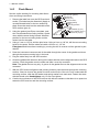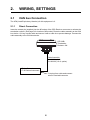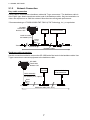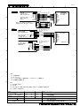
1
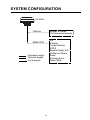
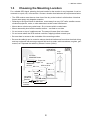
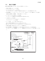
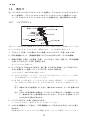
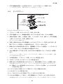
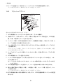
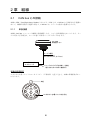
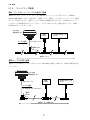
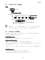
OPERATOR'S MANUAL 取扱説明書 GPS RECEIVER GPS受信機 Model GP-330B Part no. 17-468-01 rev. 04 www.furuno.com IMPORTANT NOTICES General • This manual has been authored with simplified grammar, to meet the needs of international users. • The operator of this equipment must read and follow the descriptions in this manual. Wrong operation or maintenance can cancel the warranty or cause injury. • Do not copy any part of this manual without written permission from FURUNO. • If this manual is lost or worn, contact your dealer about replacement. • The contents of this manual and equipment specifications can change without notice. • The example screens (or illustrations) shown in this manual can be different from the screens you see on your display. The screens you see depend on your system configuration and equipment settings. • Save this manual for future reference. • Any modification of the equipment (including software) by persons not authorized by FURUNO will cancel the warranty. • All brand and product names are trademarks, registered trademarks or service marks of their respective holders. How to discard this product Discard this product according to local regulations for the disposal of industrial waste. For disposal in the USA, see the homepage of the Electronics Industries Alliance (http://www.eiae.org/) for the correct method of disposal. How to discard a used battery Some FURUNO products have a battery(ies). To see if your product has a battery, see the chapter on Maintenance. Follow the instructions below if a battery is used. Tape the + and - terminals of battery before disposal to prevent fire, heat generation caused by short circuit. In the European Union The crossed-out trash can symbol indicates that all types of batteries must not be discarded in standard trash, or at a trash site. Take the used batteries to a battery collection site according to your national legislation and the Batteries Directive 2006/66/EU. Cd In the USA The Mobius loop symbol (three chasing arrows) indicates that Ni-Cd and lead-acid rechargeable batteries must be recycled. Take the used batteries to a battery collection site according to local laws. Ni-Cd Pb In the other countries There are no international standards for the battery recycle symbol. The number of symbols can increase when the other countries make their own recycle symbols in the future. i SAFETY INSTRUCTION The operator of this equipment must read these safety instructions before attempting to operate the equipment. WARNING Indicates a potentially hazardous situation which, if not avoided, could result in death or serious injury. CAUTION Indicates a potentially hazardous situation which, if not avoided, may result in minor or moderate injury. Warning, Caution Prohibitive Action Mandatory Action CAUTION WARNING Do not disassemble the unit. Always wear safety goggles and a dust mask when installing to avoid personal injury. Disasembling the unit will damage the waterproof seal. Further, there are no user-serviceable parts inside. CAUTION GPS position and velocity accuracies are controlled by the U.S. Department of Defense. Therefore, the position accuracy described in the specifications cannot be guaranteed. The input voltage shall be 12 VDC. Any other input voltage can damage the equipment. No one navigation device should ever be solely relied upon for the navigation of a vessel. Make power connections to a 12 VDC power source that is isolated from the engine start battery(s). Always confirm position against all available aids to navigation, for safety of vessel and crew. Voltage drop may cause the GPS receiver to lose information and/or change operating mode. The compass safe distance for standard and steering compasses is 0.30 m. A safe installation requires a 0.5 amp fast-blow fuse or circuit breaker. Observe this distance to prevent inteference to a magnetic compass. ii TABLE OF CONTENTS Note: This manual contains both English and Japanese instructions. The Installation Materials, Outline Drawings, and Interconnection Diagram are located at the back of this manual. FOREWORD ...................................................................................................................iv SYSTEM CONFIGURATION ...........................................................................................v 1. INSTALLATION ........................................................................................................1 1.1 Equipment Lists............................................................................................................. 1 1.2 Tools & Materials .......................................................................................................... 1 1.3 Choosing the Mounting Location................................................................................... 2 1.4 Mounting ....................................................................................................................... 3 1.4.1 Pole/Rail (Pipe) Mount........................................................................................... 3 1.4.2 Deck Mount............................................................................................................ 4 1.4.3 Flush Mount ........................................................................................................... 5 2. WIRING, SETTINGS .................................................................................................6 2.1 CAN bus Connection..................................................................................................... 6 2.1.1 Direct Connection .................................................................................................. 6 2.1.2 Network Connection .............................................................................................. 7 2.1.3 Routing and Connecting the Cable Assembly ....................................................... 8 2.2 NMEA 0183 Connection................................................................................................ 9 2.3 Settings for NavNet vx2 .............................................................................................. 10 3. MAINTENANCE, TROUBLESHOOTING................................................................11 3.1 Maintenance................................................................................................................ 11 3.2 Troubleshooting .......................................................................................................... 11 4. TECHNICAL INFORMATION..................................................................................12 4.1 NMEA 0183 Sentence................................................................................................. 12 4.2 NMEA 2000 PGN Commands..................................................................................... 13 SPECIFICATIONS .....................................................................................................SP-1 INSTALLATION MATERIALS ..................................................................................... A-1 OUTLINE DRAWINGS................................................................................................. D-1 INTERCONNECTION DIAGRAM ................................................................................ S-1 iii FOREWORD A Word to the Owner of the GP-330B Congratulations on your choice of the FURUNO GP-330B GPS Receiver. We are confident you will see why the FURUNO name has become synonymous with quality and reliability. Since 1948, FURUNO Electric Company has enjoyed an enviable reputation for quality marine electronics equipment. This dedication to excellence is furthered by our extensive global network of agents and dealers. This equipment is designed and constructed to meet the rigorous demands of the marine environment. However, no machine can perform its intended function unless installed, operated and maintained properly. Please carefully read and follow the recommended procedures for installation and maintenance. Thank you for considering and purchasing FURUNO equipment. Feature The GP-330B is a high performance GPS Receiver designed for any type of vessel. This compact and cost-effective receiver offers extremely accurate position fixes, within 3 meters with the WAAS mode activated. • 65 channels for receiving 12 satellites simultaneously • Output in CAN bus or NMEA 0183 format • Position fixed within approx. 60 seconds after start up • Position updated every second • Space-saving installation • Ideal position-fixing sensor for NavNet 3D series iv SYSTEM CONFIGURATION GP-330B NavNet 3D Series FI-50 Series Instruments CAN bus AIS Autopilot Current Indicator ECDIS Remote Display Unit NavNet vx2 Series Radar Scanning Sonar Video Plotter NMEA 0183 : Standard supply : Optional supply : Local supply v 1. INSTALLATION 1.1 Equipment Lists Name Type Code No. Qty Remarks Standard Supply GPS Receiver GP-330B 1 Installation Materials CP20-03200 000-012-581 1 set With CAN bus cable (6 m) CP20-03210 000-012-582 1 set No cable Cable Assy. 33-1209-01 001-193-460-10 1 6 m, for CAN bus Cable Assy. 33-1209-02 001-193-470-10 1 10 m, for CAN bus Cable Assy. 22-910-03 001-163-140-10 1 10 m, for NMEA 0183 Cable Assy. MJ-A7SPF/ SRMD-100 000-144-534-11 1 10 m, straight, MJ7P(P)-MJ7P(J), for NMEA 0183 Flush Mount Kit GP-330BFLUSH KIT 001-037-630 Deck Mount Kit GP-330BDECK KIT 001-037-640 Pipe Mount Kit GP-330BPIPE KIT Optional Supply 1.2 1 1 001-041-560 1 Tools & Materials • • • • • • • • Mounting hardware with standard 1-14" UNS (Pole/Rail Mount installation) threads Safety goggles Dust mask Screwdrivers (Pole/Rail Mount or Deck Mount installation) Teflon pipe thread tape, 1/2" wide (some installations) Pencil (some installations) Electric drill (some installations) Drill bits (some installations): • Pilot hole - 3 mm or 1/8" • Deck mount screw holes - 5.1 mm or #7 • Deck mount cable hole - 25 mm or 1” • Flush mount stud holes - 6 mm or 1/4” • Flush mount cable hole - 38 mm or 1-1/2” • Loctite 242 or removable thread locker (Flush Mount installation) • Cable ties (some installations) 1 1. INSTALLATION 1.3 Choosing the Mounting Location For a reliable GPS signal, selecting the best location for the receiver is very important. It can be mounted on a pole, rail, or flat surface. Choose a location that balances the requirements below. • The GPS receiver must have a clear view of the sky to the horizon in all directions. Note that frozen water spray may degrade reception. • Referring to the figure below for distances, mount away from any VHF radio, satellite communications equipment, radar, or other antennas to avoid mutual interference. • Mount above or below any radar beam. Do not mount within a radar beam. • Mount reasonably level with the earth’s surface -- not tilted to one side. • Do not mount on top of a sailboat mast. The sway will cause jitter in the data. • Do not mount where the GPS receiver could be a tripping hazard or tread upon. • Be sure there is access to the underside of the mounting surface. • Be sure the cable(s) can be routed to reduce electrical interference from other electrical wiring and any equipment with a strong magnetic field such as radar, radio transmitters, engines, generators, etc. Separate the cables by at least 1 meter (3 feet). VHF antenna or RX MF/HF whip antenna Loop antenna not within INMARSAT beam B-, F-type: 25° C-type: 15° INMARSAT antenna Min. 5 m Min. 3 m GPS receiver Min. 1 m Min. 4 m Min. 1.5 m Min. 1 m Radar Long-wire TX MF/HF antenna Antenna insulator not within radar beam Min. 5 m Min. 4 m 2 TX whip antenna (MF/HF) 1. INSTALLATION 1.4 Mounting 1.4.1 Pole/Rail (Pipe) Mount CAUTION! - Do not use the flush mount materials to mount the unit on a pole. Water may leak into the unit. 2) 1) The nut assembly supplied has standard 1-14" UNS threads that can be screwed to a standard marine antenna mount, extension pole, or rail-mount bracket. Before beginning the installation, plan for securing the pole/rail bracket to the boat and purchase locally all the necessary hardware. It may be helpful to fasten the pole/rail bracket to the boat before proceeding. 1. Unscrew the mount base (part C) from the surface bracket (part E). (The surface bracket is not used in this installation. See the next page for part (E)). 2. Remove the label from the GPS receiver’s socket (underside of receiver). The label may be discarded. Fasten the mount base (part C) to the GPS receiver (part A) with the supplied two panhead screws, flat washers and spring washers. The torque for the screws is 1.35 N m. 3. Decide if you want the cable to exit through the center or along the side of the pole/rail bracket. Slide the nut assembly (captive nut and adaptor) onto the cable at the 9-pin GPS connector end. Do not connect the GPS receiver at this time. 1) Center exit: Pass the instrument connector end of the cable down through the center of the pole. Be sure to leave several inches of cable extending beyond the nut assembly. 2) Side exit: Place the cable side-exit adaptor (part D) over the cable. Being sure the cable is passing through the slot in the side, screw the nut assembly onto the adaptor. Handtighten only. Do not over tighten. Note: Use the adaptor supplied as it has smooth edges that will not chafe the cable. Do not use a purchased part. CAUTION: if you use a thread locker, use teflon pipe thread tape. Do not use a liquid thread locker as it may weaken the plastic, causing it to swell and crack. 4. Screw the extension pole/rail bracket onto the nut assembly/cable side-exit adaptor. Handtighten only. Do not over tighten. 5. Remove the protective cap from the GPS connector on the cable. (Save the cap to protect the connector, when the receiver is removed.) Plug the cable firmly into the GPS receiver. 6. With the alignment tab on the GPS receiver facing forward, slide the captive nut upward and screw it onto the mount base. Hand-tighten only. Do not over tighten. 3 1. INSTALLATION 1.4.2 Deck Mount Aligment tab GPS receiver (part A) Mount base (part C) Panhead screw (2 pcs.) GPS connector Self-tapping screw (3 pcs.) #10x1/2" Flat washer (2 pcs.) Spring washer (2 pcs.) Silicone sealant Surface bracket (part E) Drain slot (6) Silicone sealant See the outline drawing for mounting hole dimensions and fixing instructions 1. Unscrew the mount base (part C) from the surface bracket (part E) (see figure above). Remove the label from over the GPS receiver's socket. (The label may be discarded.) Fasten the mount base (part C) to the GPS receiver (part A) with the supplied panhead screws, flat washers and spring washers. The torque for the screws is 1.35 N m. 2. Screw the surface bracket (part E) onto the mount base of the assembled GPS receiver. Use a pencil to extend the alignment tab onto the surface bracket. Unscrew the surface bracket. 3. At the selected location, position the surface bracket with the pencil mark facing forward. Using it as a template, mark the position for the three mounting screws and the center hole for the cable. 4. Using a 3 mm or 1/8" bit, drill the pilot holes. Using 5.1 mm or #7 bit, drill the three mounting holes. Drill the cable hole with a 25 mm or 1" bit. Fiberglass-Minimize surface cracking by running the drill in reverse until the gelcoat is penetrated. 5. At the location shown in the figure above, coat the surface bracket (part E) with silicone sealant. 6. Apply silicone sealant to the three #10 x 1/2" self-tapping screws to seal the deck. With the pencil mark facing forward, fasten the surface bracket in place. Do not block the drain slots. They will allow any water that accumulates inside the surface bracket to escape. CAUTION: Do not use a liquid thread locker as it may weaken the plastic, causing it to swell and crack. 7. Wrap pipe thread tape around the threads of the mount base two times to seal it tightly to the surface bracket. 8. Coat the part of the GPS connector shown in the figure on page 4 with silicone sealant. Pass the GPS connector end of the cable up through the hole in the surface bracket. 9. Remove the protective cap from the cable's GPS connector. (Save the cap to protect the connector, when the receiver is removed.) Plug the cable firmly into the GPS receiver. 10. Counterclockwise twist the cable three and one-half turns. Then screw the GPS receiver onto the installed surface bracket. Hand-tighten only. Do not over tighten. 4 1. INSTALLATION 1.4.3 Flush Mount See the outline drawing for mounting hole dimensions and fixing instructions. 1. Remove the label from over the GPS receiver's socket. (The label may be discarded.) Apply removable thread locker to the two studs supplied. Screw the studs into the underside of the GPS receiver (part A). 2. Using the gasket (part B) as a template, position it at the selected mounting location upside down with the arrow facing forward. Mark the position for the two mounting holes and the center hole for the cable. GPS receiver (part A) Aligment tab Stud (2 pcs.) GPS connector Gasket (part B) Arrow Mounting surface Flat washer (2 pcs.) Spring washer (2 pcs.) Thumb nut (2 pcs.) 3. Using a 3 mm or 1/8" bit, drill the pilot holes. Using a 6 mm or 1/4" bit, drill the two mounting holes for the studs. Drill the cable hole with a 38 mm or 1-1/2" bit. Fiberglass-Minimize surface cracking by running the drill in reverse until the gelcoat is penetrated. 4. Pass the instrument connector-end of the cable through the center of the gasket and down through the center mounting hole in the boat. 5. Plug the cable firmly into the GPS receiver. 6. Orient the gasket with the arrow facing in the same direction as the alignment tab on the GPS receiver. Push the gasket onto the studs and slide it over the connector. Note: The gasket fits one way only. A groove in the gasket fits over the alignment tab on the connector. 7. With the GPS receiver alignment tab pointing forward, push the studs through the mounting surface. Check to be sure the gasket is tucked under the lip of the unit. From underneath the mounting surface, slide the flat washer and spring washer onto each stud. Fasten the studs with the thumb nuts. Hand-tighten only. Do not over tighten. 8. Coat the circumference of the GPS receiver with silicone sealant so that there is no space between the GPS receiver and the mounting surface. 5 2. WIRING, SETTINGS 2.1 CAN bus Connection The LEN (Load Equivalency Number) for this equipment is 2. 2.1.1 Direct Connection Insert the contact pin (supplied) into the #5 socket of the GPS Receiver connector to activate the termination resistor. (See page 8 for location of #5 socket.) Route the cable assembly to the CAN bus device. Coil any excess cable and secure it with a cable tie to prevent damage. Connect the cable assembly to the CAN bus device. GP-330B Termination Resistor: ON Cable Assembly 33-1209-01 (6 m) 33-1209-02 (10 m, option) - Radar Sensor* - FI-50 Series Instrument * Cut plug from cable and connect wires to terminal/connector. 6 2. WIRING, SETTINGS 2.1.2 Network Connection Drop cable connection A drop cable is connected to a backbone cable with T-type connectors*. The backbone cable is of the "light" type. Attach a terminator at the ends of the backbone cable. Only two termination resistors are required on an CAN bus network. More than two will degrade performance. * Recommended type: LTWSS-050505-FMF-TS001 (LTW Technology, Inc.), or equivalent GP-330B Termination Resistor: OFF Power (12 VDC) - NavNet 3D Series - FI-50 Instrument Cable Assembly 33-1209-01 (6 m) Power (12 V) Terminator 1 T-connector T-connector T-connector Terminator 2 Backbone cable Backbone cable connection Use this connection method to connect the GP-330B at the final node in the backbone cable. Use T-type connectors to connect equipment to the backbone cable. GP-330B Termination Resistor: ON Power (12 VDC) Cable Assembly 33-1209-01 (6 m) 33-1209-02 (10 m, option) - NavNet 3D Series - FI-50 Instrument Power (12 V) T-connector T-connector Backbone cable (max. 25 m) 7 T-connector 2. WIRING, SETTINGS Connect the GPS Receiver at the last node in the network. Insert the contact pin (supplied) into the #5 socket of the GPS Receiver connector to activate the termination resistor. Tab 2.1.3 Contact pin inserted in #5 socket Routing and Connecting the Cable Assembly Route the cable assembly to the CAN bus device. Coil any excess cable and secure it with a cable tie to prevent damage. Connect the cable assembly to the CAN bus device. 8 2. WIRING, SETTINGS 2.2 NMEA 0183 Connection Wiring outline GP-330B NMEA 0183 Cable Assembly (22-910-03, 10 m, option) Female Extension cable (MJ-A7SPF/SRMD-100, option) max. length: 50 m Female Remote Display Unit (RD-30) NavNet vx2 Series Waterproof connectors by wrapping them with vulcanizing tape and then vinyl tape. Bind tape ends with suitable cable ties. Wiring procedure Route the cable assembly to the display. Coil any excess cable and secure it with a cable tie to prevent damage. Connect the GPS Receiver to your NMEA 0183 display. 9 2. WIRING, SETTINGS 2.3 Settings for NavNet vx2 The following items in the NavNet vx2 menu system are applicable to the GP-330B. For details and operating procedure, see the Installation Manual for your NavNet vx2 model. NAV SETUP menu Set POSITION SOURCE to GPS or ALL. GPS SETUP menu • GEODETIC DATUM Select your chart type. WGS-84 is the GPS standard. • FIX MODE Set position fixing mode to 2D/3D (three or four satellites in view). • COLD START Clear the Almanac currently stored in the GPS receiver to receive the latest Almanac. WAAS SETUP menu • WAAS MODE Select ON to use the WAAS mode. • WAAS SEARCH Set WAAS satellite search method to automatic. • CORRECTIONS DATA Select the type of message for WAAS connection, 00 for North America, 02 elsewhere. WAAS settings effective from the version numbers shown below. C-MAP specification Program No. NAVIO specification Model Program No. Model 1950026-03.02 Model 1804C-BB 1950025-03.02 Model 1804C-BB 1950024-03.02 Model 1804C 1950023-03.02 Model 1804C 1950028-03.02 Model 1704C 1950027-03.02 Model 1704C 10 3. MAINTENANCE, TROUBLESHOOTING NOTICE CAUTION Do not disassemble the unit. Do not apply paint, anticorrosive sealant or contact spray to coating or plastic parts of the equipment. Disassembling the unit will damage the waterproof seal. Further, there are no user-serviceable parts inside. Those items contain organic solvents that can damage coating and plastic parts, especially plastic connectors. Do not immerse in water or pressure wash. Doing so may allow water to infiltrate the sensor, voiding the warranty. 3.1 Maintenance The GP-330B is virtually maintenance free. However, it is recommended to wipe it with a watermoistened cloth periodically to remove accumulated dirt and water deposits. 3.2 Troubleshooting If position is not found within a reasonable amount of time, check the following items. • Is there power to the GPS receiver? (Check unit that is supplying power to the GP-330B.) • Are all the connections tight? • Does the GPS receiver have a clear view of the sky? • Is there interference from other antennas or instruments? • Is cabling damaged? • Is the cable-run free of kinks or damage? • Is there damage to the GPS receiver? • Is there ice on the GPS receiver? 11 4. TECHNICAL INFORMATION 4.1 NMEA 0183 Sentences Transmitted NMEA 0183 Sentences $GPDTM* Datum Reference $GPGGA* GPS Fix Data $GPGLL* Geographic Position -Latitude / Longitude $GPGSA GNSS DOP and Active Satellites $GPGSV GNSS Satellites in View $GPRMC* Recommended Minimum Specific GNSS Data $GPVTG* Course Over Ground and Ground Speed $GPZDA* Time and Date $PFEC,pidat Response to $PFEC,pireq * Default output Received NMEA 0183 Sentences and Commands $PAMTC,BAUD Change the baud rate from the nominal 4800 baud to 38400 baud $PAMTC,EN Enable/disable transmission of specific sentences, and change their rate of transmission $PAMTC,ERST Reset the user portion of nonvolatile EEPROM to factory defaults $PAMTC,OPTION WAAS ON/OFF. Set 3d/Auto mode. $PAMTC,POST Set Query Power On Self Test function $PAMTC,QPS Query part number and serial number versions $PAMTC,QV Query GPS hardware and firmware versions $PAMTC,RESET Reset the GP-330B $PAMTC,SIM Enable/disable Simulate Mode $PAMTX Pause or resume all automatic transmission of messages $PFEC,pireq Request to $PFEC,pidat 12 4. TECHNICAL INFORMATION 4.2 NMEA 2000 PGN Commands Transmitted NMEA 2000 PGNs PGN 059392 ISO Acknowledgment PGN 060928 ISO Address Claim PGN 065285 Proprietary: Boot State Acknowledgment PGN 065287 Proprietary: Access Level PGN 126208 Acknowledge Group Function PGN 126464 PGN List - Transmit/Received PGN's Group PGN 126720 Addressable Multi-Frame Proprietary PGN 126992 System Time PGN 126996 Product Information PGN 126998 Configuration Information PGN 127258 Magnetic Variation PGN 129025 Position, Rapid Update PGN 129026 COG & SOG, Rapid Update PGN 129029 GNSS Position Data PGN 129033 Time & Date PGN 129044 Datum PGN 129538 GNSS Control Status PGN 129539 GNSS DOPs PGN 129540 GNSS Sats in View Received NMEA 2000 PGNs PGN 059904 ISO Request PGN 060928 ISO Address Claim PGN 126208 Request Group Function PGN 126208 Command Group Function PGN 126720 Addressable Multi-Frame Proprietary 13 FURUNO GP-330B SPECIFICATIONS OF GPS RECEIVER GP-330B 1 1.1 1.2 1.3 1.4 GENERAL Receiving frequency Tracking code Number of channels Accuracy 1575.42 MHz C/A code, WAAS GPS: 65 channels parallel, 12 satellites; WAAS: 1 channel GPS: 10m approx. (2drms) WAAS: 3m approx. (2drms) 1.5 Position fixing time 60 s typical (cold start) 1.6 Tracking velocity 999 kn 1.7 Position update interval 1 s (standard), 0.1 s (minimum) 2 2.1 2.2 INTERFACE Type of data CAN bus or NMEA0183 Ver.3.1 (selected by cable) Data sentences (NMEA0183) Output DTM, GGA, GLL, GSA, GSV, RMC, VTG, ZDA CAN bus PGN (NMEA2000) Input 059904, 060928, 126208/720 Output 059392, 060928, 065281/285/287,126208/464/720/992/996/998 127258, 129025/026/029/033/044/538/539/540, 130822/823/944 2.3 3 POWER SUPPLY 12 VDC: 90 mA max. 4 4.1 4.2 4.3 4.4 ENVIRONMENTAL CONDITION Ambient temperature -25°C to +55°C Relative humidity 95% or less at +40°C Degree of protection IP56 Bearing vibration IEC 60945 Ed.4 5 UNIT COLOR N9.5 SP - 1 E4452S01E 130125 重要なお知らせ • 取扱説明書の一部または全部の転載、複写は著作権者である当社の許諾が必要です。無断転 載することを固くお断りします。 • 製品の仕様ならびに取扱説明書の内容は予告なく変更することがあります。 • 画面に表示される内容は、システムの設定や動作状態によって異なります。したがって、本 書内に掲載してあるイラストは画面の表示と異なる場合があります。 • お客様が本書の内容に従わずに本機または本ソフトウェアを取り扱われたり、または当社お よび当社指定の者以外の第三者により改造・変更されることに起因して生じる障害等につい ては、当社は責任を負いかねますのでご了承ください。 • お買い上げの機器を廃棄するときは、産業廃棄物として地方自治体の条例または規則に従っ て処理してください。詳しくは、各地方自治体に問い合わせてください。 • 本マニュアルに記載されている社名、製品名は、一般に各開発メーカーの登録商標または商 標です。 䉲䊥䉝䊦⇟ภ i 安全にお使いいただくために 必ずお守りください お使いになる人や他の人への危害、財産への損害を未然に防止するため、以下のことを必ずお 守りください。表示内容を無視して誤った使い方をしたときに生じる危害や損害の程度を、本 書では次の表示で区分し、説明していますので十分に気をつけてください。 ⼊㩷๔ 䈖䈱␜䈲䇸ขᛒ䈇䉕⺋䈦䈢႐ว䇮ᱫ䉁䈢䈲㊀்䉕⽶䈉น⢻ ᕈ䈏ᗐቯ䈘䉏䉎䇹ౝኈ䈪䈜䇯 ᵈ㩷ᗧ 䈖䈱␜䈲䇸ขᛒ䈇䉕⺋䈦䈢႐ว䇮ਛ⒟ᐲ䉁䈢䈲シ்䈱்ኂ䇮 䈅䉎䈇䈲⽷↥䈻䈱៊ኂ䉕⽶䈉น⢻ᕈ䈏ᗐቯ䈘䉏䉎䇹ౝኈ䈪䈜䇯 䇸ᵈᗧ༐䇹䈱ౝኈ 䇸ᒝ䇹䈱ౝኈ 䇸ᱛ䇹䈱ౝኈ ⼊㩷๔ ᵈ㩷ᗧ ⵝ䈱䈫䈐䈲䇮ో䉄䈏䈰䈫㒐Ⴒ䊙䉴 䉪䉕↪䈜䉎䈖䈫䇯 ಽ⸃䊶ᡷㅧ䈲⛘ኻ䈚䈭䈇䈖䈫䇯 㒐᳓䉲䊷䊦䈏䈲䈏䉏䉎ᕟ䉏䈏䈅䉍䉁 䈜䇯䉁䈢䇮Ἣἴ䇮ᗵ㔚䇮䉬䉧䈱ේ࿃䈮䈭 䉍䉁䈜䇯 䉬䉧䈱ේ࿃䈮䈭䉍䉁䈜䇯 㪞㪧㪪䈮䉋䉎⟎㪆ㅦᐲᖱႎ䈲䇮䉝䊜䊥䉦 วⴐ࿖࿖㒐⋭䈮䈩▤ℂ䈘䉏䈩䈇䉁䈜䇯 ᭽䊕䊷䉳䈫৻⥌䈚䈭䈇䈖䈫䈏䈅䉍䉁 䈜䇯 ᵈ㩷ᗧ 㔚Ḯ䈲㪛㪚㪈㪉㪭䉕↪䈜䉎䈖䈫䇯 ᧄᯏන⁛䈪⥶ᶏ䈚䈭䈇䈖䈫䇯 ⷙቯᄖ䈱䉅䈱䉕䈦䈢႐ว䇮㓚䈱ේ ࿃䈮䈭䉍䉁䈜䇯 ో䈮⥶ᶏ䈜䉎䈢䉄䇮ઁ䈱ⵝ⟎䈎䉌䈱 ᖱႎ䉅⏕䈚䈩䈒䈣䈘䈇䇯 㔚Ḯ䈲㪛㪚㪈㪉㪭䈲䉣䊮䉳䊮↪㔚ᳰ䈫䈲 䈮䈜䉎䈖䈫䇯 ᰴ䈱䉮䊮䊌䉴ో〒㔌䉕⏕䈚䈩䈒䈣䈘 䈇䇯 㔚㒠ਅ䈮䉋䉍䇮㪞㪧㪪ฃାᯏ䈏ᱜ䈚䈒 േ䈚䉁䈞䉖䇯 䉮䊮䊌䉴ో〒㔌䉕⏕䈚䈭䈇䈫䇮ో 䈭ᠲ⦁䈏䈪䈐䈭䈇႐ว䈏䈅䉍䉁䈜䇯 ⵝᤨ䈮䈲㪇㪅㪌㪘䈱ㅪᢿ䊍䊠䊷䉵䇮䉁 䈢䈲䊑䊧䊷䉦䊷䉕↪ᗧ䈜䉎䈖䈫䇯 ᮡḰ䉮䊮䊌䉴 㪇㪅㪊㫄 ㋕䈱㊄ዻ䉇䇮⏛ജ䉕ᜬ䈧䉅䈱䈱䈠䈳䈮 ㄭ䈨䈔䈭䈇䈖䈫䇯 ⏛႐䈮䉋䉍䇮ᣇ⏛⍹䈏ᱜ䈚䈒േ䈚䈭 䈇น⢻ᕈ䈏䈅䉍䉁䈜䇯 ii ᠲ⥽䉮䊮䊌䉴 㪇㪅㪊㫄 目 次 はじめに .......................................................................................................................... iv システム構成.................................................................................................................... v 1章 装備 ....................................................................................................................... 1 1.1 構成表....................................................................................................................................... 1 1.2 工具 .......................................................................................................................................... 1 1.3 取付け場所................................................................................................................................ 2 1.4 取付け....................................................................................................................................... 3 2章 2.1 1.4.1 パイプマウント ................................................................................................................. 3 1.4.2 デッキマウント ................................................................................................................. 4 1.4.3 フラッシュマウント .......................................................................................................... 5 結線 ....................................................................................................................... 6 CAN bus との接続 .................................................................................................................... 6 2.1.1 単独接続 ............................................................................................................................ 6 2.1.2 ネットワーク接続.............................................................................................................. 7 2.2 NMEA0183 との接続 ................................................................................................................ 8 2.3 NavNet との接続 ...................................................................................................................... 8 3章 保守点検................................................................................................................ 9 3.1 ふだんの保守点検..................................................................................................................... 9 3.2 故障かなと思ったら ................................................................................................................. 9 4章 4.1 4.2 入出力センテンス、PGN .................................................................................... 10 NMEA0183 センテンス .......................................................................................................... 10 NMEA2000 PGN .................................................................................................................... 11 仕様 ............................................................................................................................ SP-1 パッキングリスト ........................................................................................................ A-1 外寸図 .......................................................................................................................... D-1 相互結線図 ................................................................................................................... S-1 iii はじめに このたびは、当社製品をお買い求めいただき、誠にありがとうございます。当社は 1948 年の創 業以来、数々の舶用電子機器を製造販売しており、性能、品質、信頼性については全世界の ユーザーの方々から高い評価を受けています。本機は、厳しい品質管理のもとで設計・製造さ れていますので、性能・耐久性ともに安心してご使用いただけます。この取扱説明書をよくお 読みいただき、本来の性能を十分発揮させていただきますようお願い申し上げます。 特徴 GP-330B は様々な船に対応できる高性能な GPS 受信機です。本機は WAAS システムを利用す ると、3 メートル以内の誤差で本船の位置を測位できます。 本機の主な特徴は次のとおりです。 • 同時に最大 12 個の衛星を追尾可能 • CAN bus や NMEA0183 形式で測位データを出力可能 • 測定開始から約 60 秒以内に船位確定 • NavNet 3D*1 の測位センサーとして最適 *1:古野電気株式会社の登録商標 iv システム構成 基本構成を実線で表示します。 㪞㪧㪄㪊㪊㪇㪙 㪥㪸㫍㪥㪼㫋㩷㪊㪛䉲䊥䊷䉵 㪚㪘㪥㩷㪹㫌㫊 㪝㪠㪄㪌㪇䉲䊥䊷䉵 ⦁⥾⥄േ⼂ⵝ⟎ 䉥䊷䊃䊌䉟䊨䉾䊃 ầᵹ⸘ 㔚ሶᶏ࿑䉲䉴䊁䊛㩿㪜㪚㪛㪠㪪㪀 䊥䊝䊷䊃䊂䉞䉴䊒䊧䉟 㪥㪸㫍㪥㪼㫋 䊧䊷䉻䊷 䉴䉨䊞䊆䊮䉫䉸䊅䊷 䊎䊂䉥䊒䊨䉾䉺 㪥㪤㪜㪘㪇㪈㪏㪊 v 1 章 装備 1.1 構成表 名称 標準支給品 GPS 受信機 コード番号 数量 - 1 CP20-03200 CP20-03210 000-012-581 1式 CAN bus 6m ケーブル付き 000-012-582 1式 ケーブルなし 33-1209-01 001-193-460-10 1 CAN bus 用、6m 33-1209-02 22-910-03 001-193-470-10 001-163-140-10 1 CAN bus 用、10m 1 NMEA0183 用、10m ケーブル組品 MJ-A7SPF/ SRMD-100 000-144-534-11 1 NMEA0183 用 MJ7P(P)-MJ7P(J) ストレート、10m フラッシュマウ ントキット デッキマウント キット パイプマウント キット GP-330BFLUSH KIT GP-330BDECK KIT GP-330BPIPE KIT 001-037-630 1 001-037-640 1 001-041-560 1 工事材料 オプション ケーブル組品 ケーブル組品 ケーブル組品 1.2 型式 GP-330B 備考 工具 • 1-14 UNS ネジ(ユニファイネジ)付き取付け金具(パイプマウントの場合) • 安全メガネ • 防塵マスク • ドライバ(パイプ、デッキマウントの場合) • テフロンパイプ用ネジテープ • 鉛筆 • 電気ドリル • ドリル錐 • パイロット穴用:3mm • デッキマウントネジ穴用:5mm • デッキマウントケーブル穴用:25mm • フラッシュマウントボルト穴用:6mm • フラッシュマウントケーブル穴用:38mm • ロックタイト 242、または同等のネジロック剤(フラッシュマウントの場合) • 結束バンド 1 1 章 装備 1.3 取付け場所 GPS 受信機を装備するときは、以下の点に留意してください。 • 周囲に障害物のないところを選ぶ。 • 水しぶきが当たらないところを選ぶ。 水しぶきが当たると、水が凍って GPS 信号を受信しにくくなる可能性があります。 • VHF 無線機、インマルサットアンテナ、レーダー、他のアンテナから離れたところを選ぶ。 本機と他の機器との距離は、下図を参考にしてください。 • レーダービームから外れたところを選ぶ。 レーダービームは GPS 信号の受信を妨害する恐れがあります。 • 十分に高いところを選ぶ。 フラッシュマウント、デッキマウント:取付面水平 パイプマウント:パイプが垂直 • ヨットの場合、マストの頂上に取り付けない。 揺れで正確な位置測定ができなくなる恐れがあります。 • 踏んだりつまずいたりするような恐れのあるところに取り付けない。 • 本機の底面部も点検できるようなスペースを確保する。 • 他の電子機器や、高電圧機器からの干渉を出来るだけ受けないような位置を選ぶ。 たとえば、レーダーや無線機、エンジン、発電機などからは少なくとも 1m は離してくださ い。 㪭㪟㪝䉝䊮䊁䊅䇮 䈅䉎䈇䈲ฃା䊖䉟䉾䊒 䉝䊮䊁䊅㩿㪤㪝㪆㪟㪝㪀 ㅍା䊖䉟䉾䊒 䉝䊮䊁䊅 㩿㪤㪝㪆㪟㪝㪀 䊦䊷䊒䉝䊮䊁䊅 䉟䊮䊙䊦䉰䉾䊃䊎䊷䊛䈮 䉌䈭䈇䈖䈫 㪙䇮㪝䉺䉟䊒䋺㪉㪌㫦 㪚䉺䉟䊒䋺㪈㪌㫦 ᦨዊ㪊㫄 㪞㪧㪪ฃାᯏ 䉟䊮䊙䊦䉰䉾䊃 䉝䊮䊁䊅 ᦨዊ㪌㫄 ᦨዊ㪈㫄 ᦨዊ㪈㪅㪌㫄 ᦨዊ㪈㫄 䊧䊷䉻䊷 ㅍା䉝䊮䊁䊅 ⓨਛ✢㩿㪤㪝㪆㪟㪝㪀 䉝䊮䊁䊅 ⎹ሶ 䊧䊷䉻䊷䊎䊷䊛䈮 䉌䈭䈇䈖䈫 ᦨዊ㪌㫄 ᦨዊ㪋㫄 2 ᦨዊ㪋㫄 1 章 装備 1.4 取付け 注)パイプマウントにはパイプマウントキットを使用し、デッキマウントにはデッキマウント キットを使用し、フラッシュマウントにはフラッシュマウントキットを使用してくださ い。パイプマウントにフラッシュマウントキットを使用すると、漏水の原因となります。 1.4.1 パイプマウント 㪞㪧㪪ฃାᯏ䋨㪘ㇱ䋩 ⦁㚂䊙䊷䉪 䊊䉡䉳䊮䉫䋨㪚ㇱ䋩 ᐔᐳ㊄ 䊋䊈ᐳ㊄ 㪂䊅䊔ዊ䊈䉳 䊅䉾䊃⚵ຠ 䉮䊈䉪䉺 㪈㪀 㪉㪀 䊅䉾䊃 䉝䉻䊒䉺 䉝䉻䊒䉺䋨㪛ㇱ䋩 Ḵ 支給のナット組品には 1-14 UNS ネジ(ユニファイネジ)が切ってあり、受信機ハウジングおよ びパイプに取り付けることができます。装備する前に、パイプを船体に固定します。 1. ブラケット(E 部、1.4.2 項のイラスト参照)からハウジング(C 部)を外します。 2. GPS 受信機ソケット(受信機の底面)からラベルをはがします(ラベルは廃棄)。 3. 支給の平座金(2 個)、バネ座金(2 個)、+ ナベ小ネジ(2 本)を使って、GPS 受信機 (A 部)にハウジング(C 部)を固定します。 ネジのトルクは 1.35Nm です。 4. ケーブルをパイプの中心から出すか、横(溝)から出すかを決め、ケーブルの 5 ピン コネクタ側をナット組品(ナットとアダプタ)の上から通します。 このときはまだ、GPS 受信機を接続しません。 1) 中心から出す場合:パイプにケーブルのコネクタを通します。このとき、ナット組品 より約 10cm 長くケーブルを出してください。 2) 横(溝)から出す場合:ケーブルはアダプタ(D 部)の溝を通し、ナット組品はアダ プタ(D 部)の上に取り付けます。必ず手で取り付け、あまりきつく締めないでくだ さい。 注 1)支給のアダプタを使用してください。縁がなめらかなので、ケーブルを傷つけま せん。 注 2)ネジロック剤を使用する場合は、テフロンパイプ用ネジテープを使用してくださ い。液状のネジロック剤は使用しないでください。プラスチックを弱め、ふくら んでひびが入る恐れがあります。 5. パイプにアダプタ(D 部)を取り付けます。 ナットは必ず手で回し、締めすぎないように注意してください。 6. コネクタの保護キャップを外し、GPS 受信機にケーブルのコネクタをしっかりと差し 込みます。 受信機を取り外したときにコネクタを保護するため、キャップは保管しておいてください。 3 1 章 装備 7. GPS 受信機の船首マークを前方に向けて、ハウジングをナットで固定します。 ナットは必ず手で回し、締めすぎないように注意してください。 1.4.2 デッキマウント ⦁㚂䊙䊷䉪 㪞㪧㪪ฃାᯏ䋨㪘ㇱ䋩 䊊䉡䉳䊮䉫䋨㪚ㇱ䋩 ᐔᐳ㊄ 䊋䊈ᐳ㊄ 㪂䊅䊔ዊ䊈䉳 䉮䊈䉪䉺 㪂䊃䊤䉴䉺䉾䊏䊮䊈䉳 䊑䊤䉬䉾䊃䋨㪜ㇱ䋩 ᳓ᛮ䈐Ḵ䋨㪍䊰ᚲ䋩 䉲䊥䉮䊮䉕Ⴃ䉎 巻末の外寸図を参考に取り付けてください。 1. ブラケット(E 部)からハウジング(C 部)を外します。 2. GPS 受信機ソケット(受信機の底面)からラベルをはがします(ラベルは廃棄) 。 3. 支給の平座金(2 個)、バネ座金(2 個) 、+ ナベ小ネジ(2 本)を使って、GPS 受信機 (A 部)にハウジング(C 部)を固定します。 ネジのトルクは 1.35Nm です。 4. 手順 3 で組み合わせた GPS 受信機 / ハウジングにブラケット(E 部)をねじ込み、鉛 筆でブラケットに船首マーク位置の印を付け、ブラケットを外します。 5. 鉛筆で付けた印を船首方向に向けて、装備場所にブラケットを配置し、+ トラスタッピ ンネジ(3 本)とケーブルを通す穴の位置を印します。 6. 3mm の錐を使って下穴を 3ヵ所、および 25mm の錐を使ってケーブル穴を 1ヵ所開け ます。 グラスファイバーの場合、ゲルコートがしみこむまで、逆側からドリルで穴を開け、表面 のひびを最小限におさえます。 7. 上の図を参考に、ブラケット(E 部)にシリコン剤を塗ります。 8. 3 本の + トラスタッピンネジ にシリコン剤を塗ります。 9. 鉛筆で付けた印が船首方向になるようにして、所定の場所にブラケットを固定します。 水抜き溝をふさがないでください。ブラケット内に水がたまるのを防ぐためのものです。 注)液体のシリコン剤は使用しないでください。プラスチックを弱め、ふくらんでひびが 入る恐れがあります。 10. ハウジングのネジの周りにパイプ用ネジテープを 2 回巻き付けます。 11. コネクタにシリコン剤を塗ります。 12. ケーブルの 5 ピンコネクタ側をブラケットの穴に上から通します。 13. コネクタの保護キャップを外し、GPS 受信機にケーブルをしっかりと差し込みます。 受信機を取り外したときにコネクタを保護するため、キャップは保管しておいてください。 4 1 章 装備 14. ケーブルを左回りに 3 回半ねじり、ハウジングに GPS 受信機を固定します。 ナットは必ず手で回し、締めすぎないように注意してください。 1.4.3 フラッシュマウント 㪞㪧㪪ฃାᯏ䋨㪘ㇱ䋩 ⦁㚂䊙䊷䉪 䊨䉾䊄 䉮䊈䉪䉺 䊌䉾䉨䊮䋨㪙ㇱ䋩 ⍫ශ ขઃ䈔㕙 ᐔᐳ㊄ 䊋䊈ᐳ㊄ 䊅䉾䊃 巻末の外寸図を参考に取り付けてください。 1. GPS 受信機ソケットからラベルをはがします(ラベルは廃棄)。 2. 支給のロッド(寸切りボルト:2 本)に取外し可能なネジロック剤を塗り、GPS 受信 機(A 部)の底面からロッドをねじ込みます。 3. パッキン(B 部)の矢印を船首方向に向けて、装備場所に配置し、取付け穴(2 個)と ケーブルを通す穴の位置に印を付けます。 4. 6mm の錐を使ってロッド取付け穴を 2ヵ所 , および 38mm の錐を使ってケーブル穴を 1ヵ所開けます。 グラスファイバーの場合、ゲルコートがしみこむまで、逆側からドリルで穴を開け、表面 のひびを最小限におさえます。 5. ケーブルの 5 ピンコネクタ側をパッキンの上から通し、船体に開けたケーブル穴に通 します。 6. GPS 受信機にケーブルを差し込みます。 7. パッキンの矢印を船首マークと同じ方向に向けてパッキンをロッドにはめ込み、コネ クタを固定します。 注)パッキンは一方向にしか入りません。パッキンの溝が船首マークに合うようにはめ込 んでください。 8. GPS 受信機の船首マークを前方にして、ロッドを船体の取付け面にはめ込みます。 9. 取付け面の下側から平座金(2 個)、バネ座金(2 個)、ナット(2 個)を使って、ロッ ドを固定します。 ナットは必ず手で回し、締めすぎないように注意してください。 10. GPS 受信機と取付け面に隙間がなくなるように、GPS 受信機の周りにシリコン剤を塗 布します。 5 2 章 結線 2.1 CAN bus との接続 本機の LEN(Load Equivalency Number)は 2 です。LEN とは、CAN bus から供給される電源に おいて、機器が消費する電流の単位で、CAN bus ネットワークの設計に重要なものです。 2.1.1 単独接続 本機を CAN bus フォーマット機器と直接接続します。このとき終端抵抗をオンにします。ケー ブルが長すぎる場合は、ループに巻いて結束バンドでしばっておきます。 㪞㪧㪄㪊㪊㪇㪙 ⚳┵ᛶ᛫䋺䉥䊮 䉬䊷䊑䊦⚵ຠ 㪊㪊㪄㪈㪉㪇㪐㪄㪇㪈䋨㪍㫄䋩 㪊㪊㪄㪈㪉㪇㪐㪄㪇㪉䋨㪈㪇㫄䇮䉥䊒䉲䊢䊮䋩 㪄㩷䊧䊷䉻䊷䉶䊮䉰䊷㪁 㪄㩷㪝㪠㪄㪌㪇䉲䊥䊷䉵 㪁䋺䉬䊷䊑䊦䈎䉌䊒䊤䉫䉕ಾᢿ䈚䇮⧌✢䉕 䇭㩷┵ሶบ䉁䈢䈲䉮䊈䉪䉺䈮ធ⛯䈜䉎 本機の終端抵抗 コネクタの 5 番ソケットにコンタクトピン(工事材料)を差し込むと、本機の終端抵抗がオン になります。 ⓭ 䉮䊮䉺䉪䊃䊏䊮䉕㪌⇟䉸䉬䉾䊃䈮Ꮕ䈚ㄟ䉃 6 2 章 結線 2.1.2 ネットワーク接続 基幹(バックボーン)ケーブルの途中に接続 本機のケーブル(ドロップケーブル)を CAN bus ネットワークの T 型コネクタ(LTWSS050505-FMF-TS001、あるいは同等品)に接続します。基幹ケーブルにはライトケーブル(軽量 タイプ)が使用できます。基幹ケーブルの両端に終端器を取り付けます。CAN bus ネットワー クでは 2 つの終端器を取り付けてください。3 つ以上取り付けると性能が低下します。本機の 終端抵抗はオフのままにします。 㪞㪧㪄㪊㪊㪇㪙 ⚳┵ᛶ᛫䋺䉥䊐 㔚Ḯ 㪛㪚㪈㪉㪭 㪄㩷㪥㪸㫍㪥㪼㫋㩷㪊㪛䉲䊥䊷䉵 㪄㩷㪝㪠㪄㪌㪇 䊄䊨䉾䊒䉬䊷䊑䊦 䉬䊷䊑䊦⚵ຠ 㪊㪊㪄㪈㪉㪇㪐㪄㪇㪈䋨㪍㫄䋩 㔚Ḯ㪛㪚㪈㪉㪭 ⚳┵ེ㪈 㪫ဳ䉮䊈䉪䉺 㪫ဳ䉮䊈䉪䉺 㪫ဳ䉮䊈䉪䉺 ⚳┵ེ㪉 ၮᐙ䉬䊷䊑䊦 基幹ケーブルの端に接続 基幹ケーブルの端のノードの T 型コネクタに GP-330B を接続する場合は、本機の終端抵抗をオ ンにします。 㪞㪧㪄㪊㪊㪇㪙 ⚳┵ᛶ᛫䋺䉥䊮 㔚Ḯ 㪛㪚㪈㪉㪭 䊄䊨䉾䊒䉬䊷䊑䊦 㪄㩷㪥㪸㫍㪥㪼㫋㩷㪊㪛䉲䊥䊷䉵 㪄㩷㪝㪠㪄㪌㪇 䉬䊷䊑䊦⚵ຠ 㪊㪊㪄㪈㪉㪇㪐㪄㪇㪈䋨㪍㫄䋩 㪊㪊㪄㪈㪉㪇㪐㪄㪇㪉䋨㪈㪇㫄䇮䉥䊒䉲䊢䊮䋩 㔚Ḯ 㪛㪚㪈㪉㪭 㪫ဳ䉮䊈䉪䉺 㪫ဳ䉮䊈䉪䉺 ၮᐙ䉬䊷䊑䊦䋨ᦨᄢ㪉㪌㫄䋩 7 㪫ဳ䉮䊈䉪䉺 2 章 結線 2.2 NMEA0183 との接続 結線図 㪞㪧㪄㪊㪊㪇㪙 㪥㪤㪜㪘㪇㪈㪏㪊䉬䊷䊑䊦⚵ຠ 㪉㪉㪄㪐㪈㪇㪄㪇㪊䋨㪈㪇㫄䇮㩷䉥䊒䉲䊢䊮㪀 䊜䉴䉮䊈䉪䉺 ᑧ㐳䉬䊷䊑䊦㩿㪤㪡㪄㪘㪎㪪㪧㪝㪆㪪㪩㪤㪛㪄㪈㪇㪇䇮㩷䉥䊒䉲䊢䊮㪀 䊥䊝䊷䊃䊂䉞䉴䊒䊧䉟 ᦨᄢ㪋ᧄ 䋨㪩㪛㪄㪊㪇䋩 㪥㪸㫍㪥㪼㫋 䊜䉴䉮䊈䉪䉺 䊜䉴䉮䊈䉪䉺 䉮䊈䉪䉺䈮⥄ᏆⲢ⌕䊁䊷䊒䈫䊎䊆䊷䊦䊁䊷䊒䉕Ꮞ䈐䇮㒐᳓ಣℂ䉕ⴕ䈉䇯 ⚿᧤䊋䊮䊄䈪䊁䊷䊒䈱ਔ┵䉕࿕ቯ䈜䉎䇯 配線 本機から NMEA0183 フォーマットの機器まで配線します。ケーブルは最大 50m まで延長可能 です。ケーブルが長すぎる場合は、ループに巻いて結束バンドでしばっておきます。 2.3 NavNet との接続 本機を NavNet に接続した場合、下記の設定を行ってください。操作手順などの詳細について は、NavNet の装備要領書を参照してください。 航法装置設定メニュー [ 外部航法装置選択 ] を [ 古野 GPS センサー ] または [ 全て ] に設定します。 GPS センサー設定メニュー • 測地系:チャートの種類を選択します。WGS-84 が GPS の標準です。 • 測位モード:[2D/3D] に設定します。( [2D/3D]:2 次元測位 (3 個の衛星 )、あるいは 3 次元測 位(4 個の衛星)) • GPS コールドスタート:現在持っているアルマナックデータを消去してから測位を開始しま す。 WAAS 設定メニュー • WAAS 受信:WAAS 測位を行うときは [ する ] を選択します。 • WAAS 衛星選択:WAAS 衛星の選択方法を [ 自動 ] に設定します。 8 3 章 保守点検 䈗ᵈᗧ ᵈ㩷ᗧ ಽ⸃䊶ᡷㅧ䈲⛘ኻ䈚䈭䈇䈖䈫䇯 Ⴃᢱ䇮㒐㍕䇮ធὐᓳᵴ䈭䈬䈲ᯏ ṁ䉕䉖䈪䈇䉎䈱䈪䇮ᯏེ䈱Ⴃⵝㇱ ಽ䉇᮸⢽ㇱຠ䈮䈲↪䈚䈭䈇䈪䈒䈣䈘䈇䇯 㒐᳓䉲䊷䊦䈏䈲䈏䉏䉎ᕟ䉏䈏䈅䉍䉁䈜䇯 䉁䈢䇮Ἣἴ䇮ᗵ㔚䇮䉬䉧䈱ේ࿃䈮䈭䉍䉁 䈜䇯 ᯏེ䈱Ⴃⵝㇱಽ䉇᮸⢽ㇱຠ䉕ഠൻ䈘䈞䉎 䈖䈫䈏䈅䉍䉁䈜䇯․䈮䇮᮸⢽䈱䉮䊈䉪䉺䈮 ↪䈜䉎䈫⎕៊䈜䉎ᕟ䉏䈏䈅䉍䉁䈜䈱䈪⛘ኻ 䈮↪䈚䈭䈇䈪䈒䈣䈘䈇䇯 ᳓ᴚ䈘䈞䈢䉍䇮㜞ᵞᵺ䈲䈚䈭䈇䈖䈫䇯 ᯏེౝㇱ䈱䉶䊮䉰䊷䈏᳓ᴚ䈮䉋䉍䇮 㓚䈱ේ࿃䈮䈭䉍䉁䈜䇯 3.1 ふだんの保守点検 GP-330B はほとんどお手入れする必要はありませんが、定期的に水を湿らせた布でこびりつい た汚れや水あかをふいてください。 3.2 故障かなと思ったら 故障かなと思ったら、まず次のような点検を行ってください。 • GPS 受信機に電源が入っているか。(GP-330B に電源を供給している機器をチェックする。) • すべての機器が確実に接続されているか。 • GPS 受信機の周りに障害物がないか。 • 他のアンテナや機器からの干渉はないか。 • ケーブルが傷んでいないか。 • GPS 受信機が傷付いていないか。 • GPS 受信機に着氷していないか。 9 4 章 入出力センテンス、PGN 4.1 NMEA0183 センテンス 本機で採用している NMEA0183 の出力センテンスは以下のとおりです。 $GPDTM* 測地系 $GPGGA* GPS の測位状況 $GPGLL* 緯度・経度 $GPGSA GPS の DOP 値と衛星番号 $GPGSV 視界内の衛星情報 $GPRMC* GPS 航法情報 $GPVTG* 進路、対地船速 $GPZDA* UTC 時刻、日付 $PFEC,pidat $PFEC,pireq への応答 *: デフォルト出力 10 4 章 入出力センテンス、PGN 4.2 NMEA2000 PGN 本機で採用している NMEA2000 の PGN(パラメータグループナンバー)は以下のとおりです。 送信 PGN059392 応答 PGN060928 アドレス要求 PGN065285 起動状態応答(メーカー独自) PGN065287 アクセスレベル(メーカー独自) PGN126208 要求 / 命令応答グループ機能 PGN126464 送受信 PGN リスト PGN126720 アドレス可能マルチフレーム(メーカー独自) PGN126992 システム時刻 PGN126996 製品情報 PGN126998 構成情報 PGN127258 磁気偏差 PGN129025 緯度・経度 PGN129026 対地船速、進路 PGN129029 GNSS 測位位置 PGN129033 UTC 時刻、日付 PGN129044 測地系 PGN129538 GNSS 受信機パラメータ PGN129539 DOP 値(HDOP、VDOP、TDOP) PGN129540 視界内 GNSS 衛星情報 入力 PGN059904 要求 PGN060928 アドレス要求 PGN126208 要求グループ機能 PGN126208 命令グループ機能 PGN126720 アドレス可能マルチフレーム(メーカー独自) 11 FURUNO GP-330B GPS 受信機 GP-330B 仕様 1.総合 (1) 受信周波数 1575.42 MHz (2) 受信コード C/A コード、WAAS (3) チャンネル数 GPS: 65 チャンネル、12 衛星追尾、パラレル WAAS: 1 チャンネル (4) 測位精度 GPS: 10 m 以下(2drms) WAAS: 3 m 以下(2drms) (5) 初期捕捉時間 約 60 秒(コールドスタート時) (6) 追尾速度 999 kn (7) 測位更新周期 1 秒(標準)、0.1秒(最小) 2.インターフェイス (1) データの種類 CAN bus または NMEA0183 Ver.3.1(ケーブル選択) (2) データセンテンス(NMEA0183) 出力 DTM, GGA, GLL, GSA, GSV, RMC, VTG, ZDA (3) CAN bus PGN(NMEA2000) 入力 059904, 060928, 126208/720 出力 059392, 060928, 065281/285/287,126208/464/720/992/996/998 127258, 129025/026/029/033/044/538/539/540, 130822/823/944 3.電源 DC 12 V: 90 mA 以下 4.環境条件 (1) 使用温度範囲 -25℃ ~+55℃ (2) 相対湿度 95%以下(+40℃) (3) 保護等級 IP56 (4) 振動 IEC60945 Ed.4 5.ユニットカラー N9.5 SP - 1 J4452S01E 130125 FLUSH MOUNT KIT. 000-168-932-10 04-672-01 000-168-934-10 20-613-01 000-160-546-10 03-312-01 000-160-545-10 03-314-01 000-160-544-10 03-317-01 000-168-928-10 04-670-01 000-168-925-10 04-565-01 000-168-926-10 04-564-01 000-168-927-10 04-673-01 000-012-580-00 GP-330B DESCRIPTION/CODE № GP-330B-A (略図の寸法は、参考値です。 DIMENSIONS IN DRAWING FOR REFERENCE ONLY.) (*1),(*2),(*3)は、それぞれ組立てられています。 (*1),(*2),(*3) PRE-ASSEMBLED. GASKET パッキン THUMB NUT ナット フラッシュマウントキット FLAT WASHER 平座金 SPRING WASHER バネ座金 PANHEAD SCREW +ナベコネジ MOUNT BASE ハウジング CAPTIVE NUT ナット ADAPTOR アダプター OUTLINE PIPE MOUNT KIT. UNIT CABLE SIDE-EXIT ADAPTOR アダプター パイプマウントキット GPS RECEIVER GPS受信機 ユニット NAME PACKING LIST 1 (*3) 2 2 2 2 (*1) 1 (*2) 1 (*2) 1 1 1 Q'TY INSTALLATION MATERIALS DOCUMENT 1/1 000-174-531-1* C42-01005-* 000-168-896-1* OMC-44520-* 000-168-935-10 05-251-01 001-193-460-10 33-1209-01 *6M* 000-168-930-10 04-691-01 000-168-931-10 #10X1/2 000-168-933-10 03-282-01 DESCRIPTION/CODE № 1 1 2 1 (*1) 1 3 (*3) 2 Q'TY C4452-Z01-H TWO TYPES AND CODES MAY BE LISTED FOR AN ITEM. THE LOWER PRODUCT MAY BE SHIPPED IN PLACE OF THE UPPER PRODUCT. QUALITY IS THE SAME. 型式/コード番号が2段の場合、下段より上段に代わる過渡期品であり、どちらかが入っています。 なお、品質は変わりません。 FLUSH MOUNTING NOTICE 埋め込みキット注意書 OPERATOR'S MANUAL(JP/EN) 取扱説明書J/E 図書 CONTACT PIN コンタクトピン OUTLINE DECK MOUNT KIT. NMEA2000 CABLE ASSEMBLY ケーブル(クミヒン) 工事材料 SURFACE BRACKET ブラケット SELF-TAPPING SCREW +トラスタッピンネジ デッキマウント STUD ロッド NAME 20BD-X-9851 -8 A-1 FLUSH MOUNT KIT. 000-168-933-10 03-282-01 000-168-932-10 04-672-01 000-160-546-10 03-312-01 000-160-545-10 03-314-01 000-160-544-10 03-317-01 000-168-928-10 04-670-01 000-168-925-10 04-565-01 000-168-926-10 04-564-01 000-168-927-10 04-673-01 000-012-580-00 GP-330B DESCRIPTION/CODE № GP-330B-N (略図の寸法は、参考値です。 DIMENSIONS IN DRAWING FOR REFERENCE ONLY.) (*1),(*2),(*3)は、それぞれ組立てられています。 (*1),(*2),(*3) PRE-ASSEMBLED. STUD ロッド GASKET パッキン フラッシュマウントキット FLAT WASHER 平座金 SPRING WASHER バネ座金 PANHEAD SCREW +ナベコネジ MOUNT BASE ハウジング CAPTIVE NUT ナット ADAPTOR アダプター OUTLINE PIPE MOUNT KIT. UNIT CABLE SIDE-EXIT ADAPTOR アダプター パイプマウントキット GPS RECEIVER GPS受信機 ユニット NAME PACKING LIST (*3) 2 1 2 2 2 (*1) 1 (*2) 1 (*2) 1 1 1 Q'TY NAME DOCUMENT INSTALLATION MATERIALS 1/1 000-174-531-1* C42-01005-* 000-168-896-1* OMC-44520-* 000-168-935-10 05-251-01 000-168-930-10 04-691-01 000-168-931-10 #10X1/2 000-168-934-10 20-613-01 DESCRIPTION/CODE № 1 1 2 (*1) 1 3 (*3) 2 Q'TY TWO TYPES AND CODES MAY BE LISTED FOR AN ITEM. THE LOWER PRODUCT MAY BE SHIPPED IN PLACE OF THE UPPER PRODUCT. QUALITY IS THE SAME. 20BD-X-9852 型式/コード番号が2段の場合、下段より上段に代わる過渡期品であり、どちらかが入っています。 なお、品質は変わりません。 FLUSH MOUNTING NOTICE 埋め込みキット注意書 OUTLINE DECK MOUNT KIT. OPERATOR'S MANUAL(JP/EN) 取扱説明書J/E 図書 CONTACT PIN コンタクトピン 工事材料 SURFACE BRACKET ブラケット SELF-TAPPING SCREW +トラスタッピンネジ デッキマウント THUMB NUT ナット 20BD-X-9852 -4 A-2 D-1 /CT4'UWOK D-2 /CT4'UWOK D-3 /CT4'UWOK 1 2 NMEA0183 指示部 DISPLAY UNIT RDP-127/138/139 A マルチディスプレイ MULTI DISPLAY RD-30 DATA1 TD1-A TD1-B RD1-H RD1-C 12V_OUT_P GND SHIELD 延長ケーブル(最大4本:50mまで) EXTENSION CABLE (MAX.4 SETS: 50m MAX.) MJ-A7SPF *2 22-910-03,10m,φ6 1 2 3 4 5 6 7 MJ-A7SPF/SRMD-100,10m *2 1 1 6 7 NAVNET NMEA2000 SHIELD 1 NET-S 2 NET-C 3 NET-H 4 ジャンクションボックス *4 NET-L 5 JUNCTION BOX *3 B NMEA2000 J603 SHIELD NC NET-S NET-C NET-H *4 NET-L レーダーセンサー RADAR SENSOR DRS2D/4D FMC1.5/6ST 1 2 3 4 5 6 *3 1 2 3 9 7 8 5 4 6 10 Vin GND TD-A TD-B RD-H RD-C SHIELD NET-H NET-L NC 1 2 4 6 5 3 9 7 8 10 Vin GND NET-H NET-L SHIELD TD-A TD-B RD-H RD-C NC GPS受信機 GPS RECEIVER GP-330B 6 7 33-1209-02,10m,φ6(*2) 33-1209-01,6m,φ6 DRAIN アカ RED クロ BLK シロ WHT アオ BLU レーダーセンサー RADAR SENSOR RSB-118(DRS4A/6A) FI-5002 (FI-501 series) 3 33-1209-02,10m,φ6(*2) 33-1209-01,6m,φ6 DRAIN アカ クロ シロ アオ GP-330B TERMINATOR: ON RED BLK WHT BLU C D 注記 *1)造船所手配。 *2)オプション。 *3)プラグを切断して各線を端子(コネクタピン)に接続する。 *4)終端抵抗を接続する。 NOTE *1: SHIPYARD SUPPLY. *2: OPTION. *3: CUT PLUG OFF FROM CABLE AND CONNECT WIRES TO TERMINAL/CONNECTOR. *4: ATTACH A TERMINATOR. DRAWN 13/Jun/2012 CHECKED 13/Jun/2012 APPROVED 14/Jun/2012 SCALE DWG.No. TITLE T.YAMASAKI 名称 H.MAKI Y.NISHIYAMA MASS C4452-C01- F NAME kg REF.No. GP-330B GPS受信機 相互結線図 GPS RECEIVER INTERCONNECTION DIAGRAM S-1 FURUNO Worldwide Warranty for Pleasure Boats (Except North America) This warranty is valid for products manufactured by Furuno Electric Co. (hereafter FURUNO) and installed on a pleasure boat. Any web based purchases that are imported into other countries by anyone other than a FURUNO certified dealer may not comply with local standards. FURUNO strongly recommends against importing these products from international websites as the imported product may not work correctly and may interfere with other electronic devices. The imported product may also be in breach of the local laws and mandated technical requirements. Products imported into other countries as described previously shall not be eligible for local warranty service. For products purchased outside of your country please contact the national distributor of Furuno products in the country where purchased. This warranty is in addition to the customer´s statutory legal rights. Warranty repairs carried out by companies/persons other than a FURUNO national distributor or a certified dealer is not covered by this warranty. 6. Warranty Limitations When a claim is made, FURUNO has a right to choose whether to repair the product or replace it. The FURUNO warranty is only valid if the product was correctly installed and used. Therefore, it is necessary for the customer to comply with the instructions in the handbook. Problems which result from not complying with the instruction manual are not covered by the warranty. FURUNO is not liable for any damage caused to the vessel by using a FURUNO product. The following are excluded from this warranty: 1. Terms and Conditions of Warranty FURUNO guarantees that each new FURUNO product is the result of quality materials and workmanship. The warranty is valid for a period of 2 years (24 months) from the date of the invoice, or the date of commissioning of the product by the installing certified dealer. a. Second-hand product b. Underwater unit such as transducer and hull unit c. Routine maintenance, alignment and calibration services. d. Replacement of consumable parts such as fuses, lamps, recording papers, drive belts, cables, protective covers and batteries. e. Magnetron and MIC with more than 1000 transmitting hours or older than 12 months, whichever comes first. f. Costs associated with the replacement of a transducer (e.g. Crane, docking or diver etc.). g. Sea trial, test and evaluation or other demonstrations. h. Products repaired or altered by anyone other than the FURUNO national distributor or an authorized dealer. i. Products on which the serial number is altered, defaced or removed. j. Problems resulting from an accident, negligence, misuse, improper installation, vandalism or water penetration. k. Damage resulting from a force majeure or other natural catastrophe or calamity. l. Damage from shipping or transit. m. Software updates, except when deemed necessary and warrantable by FURUNO. n. Overtime, extra labour outside of normal hours such as weekend/holiday, and travel costs above the 160 KM allowance o. Operator familiarization and orientation. 2. FURUNO Standard Warranty The FURUNO standard warranty covers spare parts and labour costs associated with a warranty claim, provided that the product is returned to a FURUNO national distributor by prepaid carrier. The FURUNO standard warranty includes: Repair at a FURUNO national distributor All spare parts for the repair Cost for economical shipment to customer 3. FURUNO Onboard Warranty If the product was installed/commissioned and registered by a certified FURUNO dealer, the customer has the right to the onboard warranty. The FURUNO onboard warranty includes • • • • Free shipping of the necessary parts Labour: Normal working hours only Travel time: Up to a maximum of two (2) hours Travel distance: Up to a maximum of one hundred and sixty (160) KM by car for the complete journey 4. Warranty Registration For the Standard Warranty - presentation of product with serial number (8 digits serial number, 1234-5678) is sufficient. Otherwise, the invoice with serial number, name and stamp of the dealer and date of purchase is shown. For the Onboard Warranty your FURUNO certified dealer will take care of all registrations. 5. Warranty Claims For the Standard Warranty - simply send the defective product together with the invoice to a FURUNO national distributor. For the Onboard Warranty – contact a FURUNO national distributor or a certified dealer. Give the product´s serial number and describe the problem as accurately as possible. FURUNO Electric Company, March 1, 2011 FURUNO Warranty for North America FURUNO U.S.A., Limited Warranty provides a twenty-four (24) months LABOR and twenty-four (24) months PARTS warranty on products from the date of installation or purchase by the original owner. Products or components that are represented as being waterproof are guaranteed to be waterproof only for, and within the limits, of the warranty period stated above. The warranty start date may not exceed eighteen (18) months from the original date of purchase by dealer from Furuno USA and applies to new equipment installed and operated in accordance with Furuno USA’s published instructions. Magnetrons and Microwave devices will be warranted for a period of 12 months from date of original equipment installation. Furuno U.S.A., Inc. warrants each new product to be of sound material and workmanship and through its authorized dealer will exchange any parts proven to be defective in material or workmanship under normal use at no charge for a period of 24 months from the date of installation or purchase. Furuno U.S.A., Inc., through an authorized Furuno dealer will provide labor at no cost to replace defective parts, exclusive of routine maintenance or normal adjustments, for a period of 24 months from installation date provided the work is done by Furuno U.S.A., Inc. or an AUTHORIZED Furuno dealer during normal shop hours and within a radius of 50 miles of the shop location. A suitable proof of purchase showing date of purchase, or installation certification must be available to Furuno U.S.A., Inc., or its authorized dealer at the time of request for warranty service. This warranty is valid for installation of products manufactured by Furuno Electric Co. (hereafter FURUNO). Any purchases from brick and mortar or web-based resellers that are imported into other countries by anyone other than a FURUNO certified dealer, agent or subsidiary may not comply with local standards. FURUNO strongly recommends against importing these products from international websites or other resellers, as the imported product may not work correctly and may interfere with other electronic devices. The imported product may also be in breach of the local laws and mandated technical requirements. Products imported into other countries, as described previously, shall not be eligible for local warranty service. For products purchased outside of your country please contact the national distributor of Furuno products in the country where purchased. WARRANTY REGISTRATION AND INFORMATION To register your product for warranty, as well as see the complete warranty guidelines and limitations, please visit www.furunousa.com and click on “Support”. In order to expedite repairs, warranty service on Furuno equipment is provided through its authorized dealer network. If this is not possible or practical, please contact Furuno U.S.A., Inc. to arrange warranty service. FURUNO U.S.A., INC. Attention: Service Coordinator 4400 N.W. Pacific Rim Boulevard Camas, WA 98607-9408 Telephone: (360) 834-9300 FAX: (360) 834-9400 Furuno U.S.A., Inc. is proud to supply you with the highest quality in Marine Electronics. We know you had several choices when making your selection of equipment, and from everyone at Furuno we thank you. Furuno takes great pride in customer service. (Elemental Chlorine Free) The paper used in this manual is elemental chlorine free. ・ 機器の修理・使用方法等に関するお問い合わせは、お買い上げの販売店・代理店、最寄りの 当社支店・営業所あてへお願いします。 ・ FURUNO Authorized Distributor/Dealer お問い合わせは 本書の無断複写複製(コピー)は特定の 場合を除き、当社権利侵害になります。 A : MAY 2008 D1 : SEP. 3, 2013 Printed in Japan Pub. No. OMC-44520-D1 ( ETMI ) GP-330B 00016889614