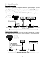
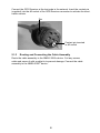
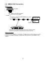
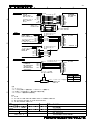
1
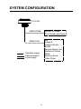
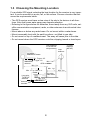
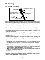
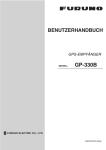
OPERATOR'S MANUAL
GPS RECEIVER
MODEL
GP-330B
www.furuno.co.jp
IMPORTANT NOTICES
• The descriptions in this manual are intended for readers with a solid knowledge
of English.
• No part of this manual may be copied or reproduced without written permission.
• If this manual is lost or worn, contact your dealer about replacement.
• The contents of this manual and equipment specifications are subject to change
without notice.
• Store this manual in a convenient place for future reference.
• FURUNO will assume no responsibility for the damage caused by improper use
or modification of the equipment (including software) by an unauthorized agent
or a third party.
• When it is time to discard this product it must be done according to local regulations for disposal of industrial waste. For disposal in the USA, refer to the Electronics Industries Alliance (http://www.eiae.org/).
• The serial number for this equipment is recorded on the underside of the GPS
receiver, which may not be visible depending on installation method. Record the
serial number below for future use.
Serial No.
i
SAFETY INSTRUCTIONS
The operator of this equipment must read these safety instructions before attempting to
operate the equipment.
WARNING
Indicates a potentially hazardous situation which, if not avoided,
could result in death or serious injury.
CAUTION
Indicates a potentially hazardous situation which, if not avoided,
may result in minor or moderate injury.
Warning, Caution
Prohibitive Action
Mandatory Action
CAUTION
WARNING
The input voltage must be 12 VDC.
Do not disassemble the unit.
Any other input voltage will damage the
equipment.
Disasembling the unit will damage
the waterproof seal. Further, there are
no user-serviceable parts inside.
Always wear safety goggles and a
dust mask when installing to avoid
personal injury.
GPS position and velocity accuracies
are controlled by the U.S. Department
of Defense. Therefore, the position
accuracy described in the specifications cannot be guaranteed.
No one navigation device should ever
be solely replied upon for the navigation of a vessel.
Always confirm position against all
available aids to navigation, for safety of
vessel and crew.
The compass safe distance for
standard and steering compasses is
0.30 m.
Observe this distance to prevent
inteference to a magnetic compass.
ii
TABLE OF CONTENTS
FOREWORD ............................................................................................... iv
SYSTEM CONFIGURATION ....................................................................... v
1. INSTALLATION ....................................................................................... 1
1.1 Equipment Lists ...........................................................................................1
1.2 Tools & Materials .........................................................................................1
1.3 Choosing the Mounting Location .................................................................2
1.4 Mounting ......................................................................................................3
1.4.1 Pole/Rail (Pipe) Mount ........................................................................3
1.4.2 Deck Mount .........................................................................................4
1.4.3 Flush Mount.........................................................................................5
2. WIRING, SETTINGS ................................................................................ 6
2.1 NMEA 2000® Connection .............................................................................6
2.1.1 Direct Connection ................................................................................6
2.1.2 Network Connection ............................................................................7
2.1.3 Routing and Connecting the Cable Assembly .....................................8
2.2 NMEA 0183 Connection ..............................................................................9
2.3 Settings for NavNet vx2 .............................................................................10
3. MAINTENANCE, TROUBLESHOOTING .............................................. 11
3.1 Maintenance ..............................................................................................11
3.2 Troubleshooting .........................................................................................11
4. TECHNICAL INFORMATION ................................................................ 12
4.1 NMEA 0183 Sentences..............................................................................12
4.2 NMEA 2000® PGN Commands ..................................................................13
SPECIFICATIONS ................................................................................. SP-1
PACKING LIST ........................................................................................ A-1
OUTLINE DRAWINGS............................................................................. D-1
INTERCONNECTION DIAGRAM ............................................................ S-1
Declaration of Conformity
iii
FOREWORD
A Word to the Owner of the GP-330B
Congratulations on your choice of the FURUNO GP-330B GPS Receiver. We are
confident you will see why the FURUNO name has become synonymous with quality and reliability.
For 60 years FURUNO Electric Company has enjoyed an enviable reputation for
quality marine electronics equipment. This dedication to excellence is furthered by
our extensive global network of agents and dealers.
This equipment is designed and constructed to meet the rigorous demands of the
marine environment. However, no machine can perform its intended function unless installed, operated and maintained properly. Please carefully read and follow
the recommended procedures for installation and maintenance.
Thank you for considering and purchasing FURUNO equipment.
Features
The GP-330B is a high performance GPS Receiver designed for any type of vessel. This compact and cost-effective receiver offers extremely accurate position fixes, within 3 meters with the WAAS mode activated.
• 12 channels for receiving 12 satellites simultaneously
• Output in NMEA 2000® or NMEA 0183 format
• Position fixed within approx. 60 seconds after start up
• Position updated every second
• Space-saving installation
• Ideal position-fixing sensor for NavNet®3D series
iv
SYSTEM CONFIGURATION
GP-330B
NMEA 2000 R
NavNet 3D Series
FI-50 Series Instruments
AIS
Autopilot
Current Indicator
ECDIS
Remote Display Unit
NavNet vx2 Series
Radar
Scanning Sonar
Video Plotter
NMEA 0183
: Standard supply
: Optional supply
: Local supply
v
1. INSTALLATION
1.1 Equipment Lists
Name
Type
Standard Supply
GPS
GP-330B
Receiver
Installation CP20-03200
Materials
CP20-03210
Code No.
Qty
Remarks
1
000-012-581
1 set With NMEA
See packing
2000 cable (6 m) list at back of
1 set No cable
manual.
000-012-582
Optional Supply
Cable Assy. 22-1025-02 000-168-883-10
1
6 m, for NMEA 2000®
Cable Assy. 22-1025-06 000-168-884-10
1
Cable Assy. 22-910-03
Cable Assy. MJ-A7SPF/
SRMD-100
Flush Mount Kit
Deck Mount Kit
000-168-885-10
000-144-534
1
1
10 m, for NMEA 2000®
10 m, for NMEA 0183
10 m, straight, MJ7P(P)MJ7P(J), for NMEA 0183
001-037-630
1
001-037-640
1
1.2 Tools & Materials
• Mounting hardware with standard 1-14" UNS (Pole/Rail Mount installation)
threads
• Safety goggles
• Dust mask
• Screwdrivers (Pole/Rail Mount or Deck Mount installation)
• Teflon pipe thread tape, 1/2" wide (some installations)
• Pencil (some installations)
• Electric drill (some installations)
• Drill bits (some installations):
• Pilot hole - 3 mm or 1/8"
• Deck mount screw holes - 5.1 mm or #7
• Deck mount cable hole - 25 mm or 1"
• Flush mount stud holes - 6 mm or 1/4"
• Flush mount cable hole - 38 mm or 1-1/2"
• Loctite®242® or other removable thread locker (Flush Mount installation)
• Cable ties (some installations)
1
1.3 Choosing the Mounting Location
For a reliable GPS signal, selecting the best location for the receiver is very important. It can be mounted on a pole, rail, or flat surface. Choose a location that balances the requirements below.
• The GPS receiver must have a clear view of the sky to the horizon in all directions. Note that frozen water spray may degrade reception.
• Referring to the figure below for distances, mount away from any VHF radio, satellite communications equipment, radar, or other antennas to avoid mutual interference.
• Mount above or below any radar beam. Do not mount within a radar beam.
• Mount reasonably level with the earth’s surface—not tilted to one side.
• Do not mount on top of a sailboat mast. The sway will cause jitter in the data.
• Do not mount where the GPS receiver could be a tripping hazard or tread upon.
VHF antenna
or RX MF/HF
whip antenna
Loop
antenna
not within
INMARSAT beam
B-, F-type: 25°
C-type: 15°
INMARSAT
antenna
Min. 5 m
Min. 3 m
GPS receiver
Min. 1 m
Min. 4 m
Min. 1.5 m Min. 1 m
Radar
Long-wire
TX MF/HF
antenna
Antenna
insulator
not within
radar beam
Min. 5 m
Min. 4 m
2
TX whip
antenna
(MF/HF)
1.4 Mounting
1.4.1 Pole/Rail (Pipe) Mount
GPS receiver (part A)
Alignment tab
Mount base (part C)
Panhead screw (2 pcs.)
Flat washer (2 pcs.)
Spring washer (2 pcs.)
GPS connector
2)
Nut
Assembly
1)
Captive nut
Adaptor
Cable side-exit
adaptor (part D)
Slot for cable exit
The nut assembly supplied has standard 1-14" UNS threads that can be screwed
to a standard marine antenna mount, extension pole, or rail-mount bracket. Before
beginning the installation, plan for securing the pole/rail bracket to the boat and
purchase locally all the necessary hardware. It may be helpful to fasten the
pole/rail bracket to the boat before proceeding.
1. Unscrew the mount base (part C) from the surface bracket (part E). (The surface bracket is not used in this installation. See the next page for part (E)).
2. Remove the label from the GPS receiver’s socket (underside of receiver). The
label may be discarded.
Fasten the mount base (part C) to the GPS receiver (part A) with the supplied
two panhead screws, flat washers and spring washers. The torque for the
screws is 1.35 NQm.
3. Decide if you want the cable to exit through the center or along the side of the
pole/rail bracket. Slide the nut assembly (captive nut and adaptor) onto the
cable at the 9-pin GPS connector end. Do not connect the GPS receiver at this
time.
1) Center exit—Pass the instrument connector end of the cable down through
the center of the pole. Be sure to leave several inches of cable extending
beyond the nut assembly.
2) Side exit—Place the cable side-exit adaptor (part D) over the cable. Being
sure the cable is passing through the slot in the side, screw the nut assembly
onto the adaptor. Hand-tighten only. Do not over tighten.
Note: Use the adaptor supplied as it has smooth edges that will not chafe the
cable. Do not use a purchased part.
CAUTION: If you use a thread locker, use teflon pipe thread tape. Do not use a
liquid thread locker as it may weaken the plastic, causing it to swell and crack.
4. Screw the extension pole/rail bracket onto the nut assembly / cable side-exit
adaptor. Hand-tighten only. Do not over tighten.
3
5. Remove the protective cap from the GPS connector on the cable. (Save the
cap to protect the connector, when the receiver is removed.) Plug the cable
firmly into the GPS receiver.
6. With the alignment tab on the GPS receiver facing forward, slide the captive nut
upward and screw it onto the mount base. Hand-tighten only. Do not over
tighten.
1.4.2 Deck Mount
Aligment tab
GPS receiver (part A)
Mount base (part C)
Panhead screw (2 pcs.)
GPS connector
Self-tapping screw (3 pcs.)
#10x1/2"
Surface bracket (part E)
Flat washer (2 pcs.)
Spring washer (2 pcs.)
Silicone sealant
Drain slot (6)
Silicone sealant
See the outline drawing for mounting hole dimensions and fixing instructions.
1. Unscrew the mount base (part C) from the surface bracket (part E) (see figure
above). Remove the label from over the GPS receiver’s socket. (The label may
be discarded.) Fasten the mount base (part C) to the GPS receiver (part A) with
the supplied panhead screws, flat washers and spring washers. The torque for
the screws is 1.35 NQm.
2. Screw the surface bracket (part E) onto the mount base of the assembled GPS
receiver. Use a pencil to extend the alignment tab onto the surface bracket.
Unscrew the surface bracket.
3. At the selected location, position the surface bracket with the pencil mark facing
forward. Using it as a template, mark the position for the three mounting screws
and the center hole for the cable.
4. Using a 3 mm or 1/8" bit, drill the pilot holes. Using 5.1 mm or #7 bit, drill the
three mounting holes. Drill the cable hole with a 25 mm or 1" bit.
Fiberglass—Minimize surface cracking by running the drill in reverse until the
gelcoat is penetrated.
5. At the location shown in the figure above, coat the surface bracket (part E) with
silicone sealant.
6. Apply silicone sealant to the three #10 x 1/2" self-tapping screws to seal the
deck. With the pencil mark facing forward, fasten the surface bracket in place.
Do not block the drain slots. They will allow any water that accumulates inside
the surface bracket to escape. CAUTION: Do not use a liquid thread locker as it
may weaken the plastic, causing it to swell and crack.
4
7. Wrap pipe thread tape around the threads of the mount base two times to seal
it tightly to the surface bracket.
8. Coat the part of the GPS connector shown in the figure on page 4 with silicone
sealant. Pass the GPS connector end of the cable up through the hole in the
surface bracket.
9. Remove the protective cap from the cable’s GPS connector. (Save the cap to
protect the connector, when the receiver is removed.) Plug the cable firmly into
the GPS receiver.
10.Counterclockwise twist the cable three and one-half turns. Then screw the
GPS receiver onto the installed surface bracket. Hand-tighten only. Do not
over tighten.
1.4.3 Flush Mount
See the outline drawing for mounting hole
dimensions and fixing instructions.
1. Remove the label from over the GPS
receiver’s socket. (The label may be discarded.) Apply removable thread locker
to the two studs supplied. Screw the
studs into the underside of the GPS
receiver (part A).
GPS receiver (part A)
Aligment tab
Stud (2 pcs.)
GPS connector
Gasket (part B)
Arrow
Mounting surface
Thumb nut (2 pcs.)
2. Using the gasket (part B) as a template,
position it at the selected mounting location upside down with the arrow facing
forward. Mark the position for the two mounting holes and the center hole for
the cable.
3. Using a 3mm or 1/8" bit, drill the pilot holes. Using a 6mm or 1/4" bit, drill the
two mounting holes for the studs. Drill the cable hole with a 38mm or 1-1/2" bit.
Fiberglass—Minimize surface cracking by running the drill in reverse until the
gelcoat is penetrated.
4. Pass the instrument connector-end of the cable through the center of the gasket and down through the center mounting hole in the boat.
5. Plug the cable firmly into the GPS receiver.
6. Orient the gasket with the arrow facing in the same direction as the alignment
tab on the GPS receiver. Push the gasket onto the studs and slide it over the
connector.
Note: The gasket fits one way only. A groove in the gasket fits over the alignment tab on the connector.
7. With the GPS receiver alignment tab pointing forward, push the studs through
the mounting surface. Check to be sure the gasket is tucked under the lip of the
unit. From underneath the mounting surface, fasten the studs with the thumb
nuts. Hand-tighten only. Do not over tighten.
5
2. WIRING, SETTINGS
2.1 NMEA 2000® Connection
The LEN (Load Equivalency Number) for this equipment is 3.
2.1.1 Direct Connection
Insert the contact pin (supplied) into the #5 socket of the GPS Receiver connector
to activate the termination resistor. (See page 8 for location of #5 socket.) Route
the cable assembly to the NMEA 2000® device. Coil any excess cable and secure
it with a cable tie to prevent damage. Connect the cable assembly to the NMEA
2000® device.
GP-330B
Termination
Resistor: ON
Cable Assembly
22-1025-02 (6 m)
22-1025-06 (10 m, option)
- NavNet 3D Series MFD
- Radar Sensor*
- FI-50 Series Instrument
* Cut plug from cable and connect
wires to terminal/connector.
6
2.1.2 Network Connection
Drop cable connection
A drop cable is connected to a backbone cable with T-type connectors*. The backbone cable is of the “light” type. Attach a terminator at the ends of the backbone
cable. Only two termination resistors are required on an NMEA 2000® network.
More than two will degrade performance.
* Recommended type: LTWSS-050505-FMF-TS001 (LTW Technology, Inc.), or
equivalent
GP-330B
Termination
Resistor: OFF
Power
(12 VDC)
- NavNet 3D Series
- FI-50 Instrument
Cable Assembly
22-1025-02 (6 m)
Power
(12 V)
Terminator 1
T-connector
T-connector
T-connector
Terminator 2
Backbone cable
Backbone cable connection
Use this connection method to connect the GP330B at the final node in the backbone cable. Use T-type connectors to connect equipment to the backbone cable.
GP-330B
Termination
Resistor: ON
Power
(12 VDC)
Cable Assembly
22-1025-02 (6 m)
22-1025-06 (10 m, option)
- NavNet 3D Series
- FI-50 Instrument
Power
(12 V)
T-connector
T-connector
Backbone cable (max. 25 m)
7
T-connector
Connect the GPS Receiver at the last node in the network. Insert the contact pin
(supplied) into the #5 socket of the GPS Receiver connector to activate the termination resistor.
Tab
Contact pin inserted
in #5 socket
2.1.3
Routing and Connecting the Cable Assembly
Route the cable assembly to the NMEA 2000® device. Coil any excess
cable and secure it with a cable tie to prevent damage. Connect the cable
assembly to the NMEA 2000® device.
8
2.2 NMEA 0183 Connection
Wiring outline
GP-330B
NMEA 0183 Cable Assembly
(22-910-03, 10 m, option)
Female
Extension cable (MJ-A7SPF/SRMD-100, option)
max. length: 50 m
Remote Display
Unit (RD-30)
NavNet vx2
Series
Female
Waterproof connectors by wrapping them with vulcanizing tape
and then vinyl tape. Bind tape ends with suitable cable ties.
Wiring procedure
Route the cable assembly to the display. Coil any excess cable and secure it with
a cable tie to prevent damage. Connect the GPS Receiver to your NMEA 0183
display.
9
2.3 Settings for NavNet vx2
The following items in the NavNet vx2 menu system are applicable to the
GP-330B. For details and operating procedure, see the Installation Manual for
your NavNet vx2 model.
NAV SETUP menu
Set POSITION SOURCE to GPS or ALL.
GPS SETUP menu
• GEODETIC DATUM
Select your chart type. WGS-84 is the GPS standard.
• ANTENNA HEIGHT
Set the height of the GPS receiver unit above the sea surface.
• FIX MODE
Select position fixing mode from 2D (three satellites in view) or 2D/3D (three or
four satellites in view).
• COLD START
Clear the Almanac currently stored in the GPS receiver to receive the latest
Almanac.
WAAS SETUP menu
• WAAS MODE
Select ON to use the WAAS mode.
• WAAS SEARCH
Select WAAS satellite search method, automatic or manual.
• CORRECTIONS DATA
Select the type of message for WAAS connection, 00 for North America, 02 elsewhere.
WAAS settings effective from the version numbers shown below.
C-MAP specification
Program No.
NAVIO specification
Model
Program No.
Model
1950026-03.02
Model 1804C-BB
1950025-03.02
Model 1804C-BB
1950024-03.02
Model 1804C
1950023-03.02
Model 1804C
1950028-03.02
Model 1704C
1950027-03.02
Model 1704C
10
3. MAINTENANCE,
TROUBLESHOOTING
NOTICE
CAUTION
Do not disassemble the unit.
Disassembling the unit will damage
the waterproof seal. Further, there
are no user-serviceable parts inside.
Do not apply paint, anticorrosive sealant or contact
spray to coatingor plastic parts
of the equipment.
Those items contain organic
solvents that can damage coating
and plastic parts, especially
plastic connectors.
3.1 Maintenance
The GP-330B is virtually maintenance free. However, it is recommended to wipe it
with a water-moistened cloth periodically to remove accumulated dirt and water deposits.
3.2 Troubleshooting
If position is not found within a reasonable amount of time, check the following
items.
• Is there power to the GPS receiver? (Check unit that is supplying power to the
GP-330B.)
• Are all the connections tight?
• Does the GPS receiver have a clear view of the sky?
• Is there interference from other antennas or instruments?
• Is cabling damaged?
• Is the cable-run free of kinks or damage?
• Is there damage to the GPS receiver?
• Is there ice on the GPS receiver?
11
4. TECHNICAL INFORMATION
4.1 NMEA 0183 Sentences
Transmitted NMEA 0183 Sentences
$GPDTM*
$GPGGA*
$GPGLL*
$GPGSA
$GPGSV
$GPRMC*
$GPVTG*
$GPZDA*
Datum Reference
GPS Fix Data
Geographic Position –Latitude/Longitude
GNSS DOP and Active Satellites
GNSS Satellites in View
Recommended Minimum Specific GNSS Data
Course Over Ground and Ground Speed
Time and Date
* Default output
Received NMEA 0183 Sentences and Commands
$PAMTC,ALT
$PAMTC,BAUD
Setting related to the altitude of the sensor
Change the baud rate from the nominal 4800 baud to 38400
baud
$PAMTC,DATUM Define local datum
$PAMTC,EN
Enable/disable transmission of specific sentences, and
change their rate of transmission
$PAMTC,ERST
Reset the user portion of nonvolatile EEPROM to factory
defaults
$PAMTC,OPTION WAAS ON/OFF. Set 2d/3d/Auto mode. Set WAAS Satellite.
Set WAAS Tzz Parameter.
$PAMTC,POST
Set Query Power On Self Test function
$PAMTC,QPS
Query part number and serial number versions
$PAMTC,QV
Query GPS hardware and firmware versions
$PAMTC,RESET Reset the GP-330B
$PAMTC,SIM
Enable/disable Simulate Mode
$PAMTX
Pause or resume all automatic transmission of messages
$PFEC,pireq
Request to $PFEC,pidat
12
4.2 NMEA 2000®PGN Commands
Transmitted NMEA 2000®PGNs
PGN 059392
PGN 060928
PGN 065285
PGN 065287
PGN 126208
PGN 126464
PGN 126720
PGN 126992
PGN 126996
PGN 126998
PGN 127258
PGN 129025
PGN 129026
PGN 129029
PGN 129033
PGN 129044
PGN 129538
PGN 129539
PGN 129540
ISO Acknowledgment
ISO Address Claim
Proprietary: Boot State Acknowledgment
Proprietary: Access Level
Acknowledge Group Function
PGN List - Transmit/Received PGN's Group
Addressable Multi-Frame Proprietary
System Time
Product Information
Configuration Information
Magnetic Variation
Position, Rapid Update
COG & SOG, Rapid Update
GNSS Position Data
Time & Date
Datum
GNSS Control Status
GNSS DOPs
GNSS Sats in View
Received NMEA 2000®PGNs
PGN 059904
PGN 060928
PGN 126208
PGN 126208
PGN 126720
ISO Request
ISO Address Claim
Request Group Function
Command Group Function
Addressable Multi-Frame Proprietary
13
FURUNO
GP-330B
SPECIFICATIONS OF GPS RECEIVER
GP-330B
1
GENERAL
1.1
Receiving frequency
1575.42 MHz
1.2
Tracking code
C/A code, WAAS
1.3
Number of channels
GPS: 12 channels parallel, 12 satellites; WAAS: 2 channels
1.4
Position fixing method
All in view, 8-state Kalman filter
1.5
Accuracy
GPS: 10m approx. (2drms)
WAAS: 3m approx. (2drms)
1.6
Position fixing time
60 s typical (cold start)
1.7
Tracking velocity
999 kt
1.8
Position update interval 1 s
2
INTERFACE
2.1
Data format
2.2
NMEA0183 format
Output sentences
2.3
NMEA2000 or NMEA0183 Ver.3.1 (selected by cable)
DTM, GGA, GLL, GSA, GSV, RMC, VTG, ZDA
NMEA2000 format
Input PGN
059904, 060928, 065280/281, 126028/208/720
Output PGN
059392, 060928, 065285/287,126208/464/720/992/996/998
127258, 129025/026/029/033/044/538/539/540, 130822/823/944
3
POWER SUPPLY
12 VDC: 175 mA max. (LEN=3)
4
ENVIRONMENTAL CONDITION
4.1
Ambient temperature
-25°C to +55°C
4.2
Relative humidity
95% at 40°C
4.3
Degree of protection
IP56
4.4
Bearing vibration
IEC 60945
5
UNIT COLOR
N9.5
SP - 1
E4452S01A
080318
FLUSH MOUNT KIT.
000-168-934-10
20-613-01
000-168-933-10
03-282-01
000-160-546-10
03-312-01
000-160-545-10
03-314-01
000-160-544-10
03-283-04
000-168-928-10
04-670-01
000-168-925-10
04-565-01
000-168-926-10
04-564-01
000-168-927-10
04-673-01
000-012-580-00
GP-330B
DESCRIPTION/CODE №
GP-330B-A
(略図の寸法は、参考値です。 DIMENSIONS IN DRAWING FOR REFERENCE ONLY.)
(*1),(*2),(*3)は、それぞれ組立てられています。
(*1),(*2),(*3) PRE-ASSEMBLED.
THUMB NUT
ナット
STUD
ロッド
フラッシュマウントキット
FLAT WASHER
平座金
SPRING WASHER
バネ座金
PANHEAD SCREW
+ナベコネジ
MOUNT BASE
ハウジング
CAPTIVE NUT
ナット
ADAPTOR
アダプター
OUTLINE
PIPE MOUNT KIT.
UNIT
CABLE SIDE-EXIT ADAPTOR
アダプター
パイプマウントキット
GPS RECEIVER
GPS受信機
ユニット
NAME
PACKING LIST
(*3)
2
(*3)
2
2
2
2
(*1)
1
(*2)
1
(*2)
1
1
1
Q'TY
NAME
DOCUMENT
INSTALLATION MATERIALS
DECK MOUNT KIT.
OUTLINE
1/1
000-168-896-1*
OME-44520-*
000-168-883-10
22-1025-02
000-168-935-10
05-251-01
000-168-930-10
04-691-01
000-168-931-10
#10X1/2
000-168-932-10
04-672-01
DESCRIPTION/CODE №
1
1
2
(*1)
1
3
1
Q'TY
TWO TYPES AND CODES MAY BE LISTED FOR AN ITEM. THE LOWER PRODUCT MAY BE SHIPPED IN
PLACE OF THE UPPER PRODUCT. QUALITY IS THE SAME.
20BD-X-9851
型式/コード番号が2段の場合、下段より上段に代わる過渡期品であり、どちらかが入っています。 なお、品質は変わりません。
OPERATOR'S MANUAL
取扱説明書
図書
CABLE ASSEMBLY
ケーブル組品
CONTACT PIN
コンタクトピン
工事材料
SURFACE BRACKET
ブラケット
SELF-TAPPING SCREW
+トラスタッピンネジ
デッキマウント
GASKET
パッキン
20BD-X-9851 -1
A-1
NAME
000-160-546-10
03-312-01
000-160-545-10
03-314-01
000-160-544-10
03-283-04
000-168-928-10
04-670-01
000-168-925-10
04-565-01
000-168-926-10
04-564-01
000-168-927-10
04-673-01
000-012-580-00
GP-330B
DESCRIPTION/CODE №
GP-330B-N
(略図の寸法は、参考値です。 DIMENSIONS IN DRAWING FOR REFERENCE ONLY.)
(*1),(*2),(*3)は、それぞれ組立てられています。
(*1),(*2),(*3) PRE-ASSEMBLED.
FLAT WASHER
平座金
SPRING WASHER
バネ座金
PANHEAD SCREW
+ナベコネジ
MOUNT BASE
ハウジング
CAPTIVE NUT
ナット
ADAPTOR
アダプター
OUTLINE
PIPE MOUNT KIT.
UNIT
CABLE SIDE-EXIT ADAPTOR
アダプター
パイプマウントキット
GPS RECEIVER
GPS受信機
ユニット
PACKING LIST
2
2
2
(*1)
1
(*2)
1
(*2)
1
1
1
Q'TY
NAME
OUTLINE
DOCUMENT
INSTALLATION MATERIALS
DECK MOUNT KIT.
FLUSH MOUNT KIT.
000-168-896-1*
OME-44520-*
000-168-935-10
05-251-01
000-168-930-10
04-691-01
000-168-931-10
#10X1/2
000-168-934-10
20-613-01
000-168-933-10
03-282-01
000-168-932-10
04-672-01
DESCRIPTION/CODE №
1/1
1
2
(*1)
1
3
(*3)
2
(*3)
2
1
Q'TY
TWO TYPES AND CODES MAY BE LISTED FOR AN ITEM. THE LOWER PRODUCT MAY BE SHIPPED IN PLACE OF
THE UPPER PRODUCT. QUALITY IS THE SAME.
20BD-X-9852
型式/コード番号が2段の場合、下段より上段に代わる過渡期品であり、どちらかが入っています。 なお、品質は変わりません。
OPERATOR'S MANUAL
取扱説明書
図書
CONTACT PIN
コンタクトピン
工事材料
SURFACE BRACKET
ブラケット
SELF-TAPPING SCREW
+トラスタッピンネジ
デッキマウント
THUMB NUT
ナット
STUD
ロッド
GASKET
パッキン
フラッシュマウントキット
20BD-X-9852 -1
A-2
D-1
18/Mar/08 R.Esumi
D-2
18/Mar/08 R.Esumi
D-3
18/Mar/08 R.Esumi
S-1
1
2
NMEA0183
指示部
DISPLAY UNIT
RDP-127/138/139
A
マルチディスプレイ
MULTI DISPLAY
RD-30
DATA1
TD1-A
TD1-B
RD1-H
RD1-C
12V_OUT_P
GND
SHIELD
MJ-A7SPF
3
*1
22-910-03,10m,φ6
1
2
3
4
5
6
7
1
2
3
9
7
8
5
4
6
MJ-A7SPF/SRMD-100,10m *1
1
1
延長ケーブル
EXTENSION CABLE
6
7
NAVNET
6
7
5
1
2
4
6
3
9
7
8
SHIELD
Vin
GND
NET-H
NET-L
TD-A
TD-B
RD-H
RD-C
22-1025-06,10m,φ6(*1 *4)
22-1025-02,6m,φ6
5
1
2
4
6
3
9
7
ドロップケーブル接続
8
DROP CABLE CONNECTION
SHIELD
Vin
GND
NET-H
NET-L
TD-A
TD-B
RD-H
RD-C
NET-C 3
ジャンクションボックス NET-H 4
NET-L 5
JUNCTION BOX
FI-5002 (FI-501 series)
*2
B
NMEA2000
J603
レーダーセンサー SHIELD
RADAR SENSOR
NC
DRS2D/4D
NET-S
NET-C
NET-H
NET-L
FMC1.5/6ST
1
2
3
4
5
6
*2
GPS受信機
GPS RECEIVER
GP-330B
*3
最大4本まで使用可能
MAX.4 SETS AVAILABLE
22-1025-06,10m,φ6(*1)
22-1025-02,6m,φ6
DRAIN
アカ RED
クロ BLK
シロ WHT
アオ BLU
レーダーセンサー NMEA2000
SHIELD 1
RADAR SENSOR
NET-S 2
RSB-118(DRS4A/6A)
Vin
GND
TD-A
TD-B
RD-H
RD-C
SHIELD
NET-H
NET-L
GP-330B
TERMINATOR: ON
22-1025-06,10m,φ6(*1)
22-1025-02,6m,φ6
DRAIN
アカ
クロ
シロ
アオ
RED
BLK
WHT
BLU
NMEA2000 NETWORK
T-コネクタ
T-CONNECTOR
LTW-SS050505FMF
-TS001(LIGHT)
LTW-NC050505FMF
-TS001(HEAVY)
1
2
3
4
5
T-コネクタ
T-CONNECTOR
D
GP-330B
接続方法
終端機能
CONNECTION TERMINATOR
6m
C
Micro-C
SHIELD
NET-S
NET-C
NET-H
NET-L
6/10m
バックボーンケーブル接続
BACKBONE CABLE
CONNECTION
DROP
OFF
BACKBONE
ON
注記
*1)オプション。
*2)プラグを切断して各線を端子(コネクタピン)に接続する。
*3)延長ケーブルを使用して、最大50mまで延長が可能。
*4)バックボーン接続時のみ使用可能。
NOTE
*1: OPTION.
*2: CUT PLUG OFF FROM CABLE AND CONNECT WIRES TO TERMINAL/CONNECTOR.
*3: MAX.50m LENGTH AVAILABLE BY USING EXTENSION CABLE.
*4: FOR ONLY BACKBONE CONNECTION.
DRAWN
24/Mar/08
CHECKED
24/Mar/08
APPROVED
SCALE
DWG.No.
TITLE
T.YAMASAKI
名称
T.TAKENO
24/Mar/08 R.Esumi
MASS
C4452-C01- A
NAME
kg
REF.No.
GP-330B
GPS受信機
相互結線図
GPS RECEIVER
INTERCONNECTION DIAGRAM
9-52 Ashihara-cho, Nishinomiya, 662-8580, Japan
Tel: +81 (798) 65-2111 Fax: +81 (798) 65-4200
www.furuno.co.jp
Publication No. DOC-986
Declaration of Conformity
We
FURUNO ELECTRIC CO., LTD.
----------------------------------------------------------------------------------------------------------------------------------------------(Manufacturer)
9-52 Ashihara-Cho, Nishinomiya City, 662-8580, Hyogo, Japan
----------------------------------------------------------------------------------------------------------------------------------------------(Address)
declare under our sole responsibility that the product
GPS receiver type: GP-330B*
----------------------------------------------------------------------------------------------------------------------------------------------(Model name, type number)
*: GP-330B is supplied by AIRMAR technology Corporation on an OEM basis and is mechanically and electronically identical to their G2183.
is in conformity with the essential requirements as described in Article 10.3 and Annex II of the Directive
1999/5/EC of the European Parliament and of the Council of 9 March 1999 on radio equipment and
telecommunications terminal equipment (R&TTE Directive) and satisfies all the technical regulations
applicable to the product within this Directive
IEC 60945 Fourth edition: 2002-08 Sub-clauses 9.2, 9.3, 10.3, 10.4, 10.5, 10.8, 10.9 and 12.1
IEC 60950-1 First edition: 2001-10
Draft EN 300 440-1 V1.4.1 Sub-clause 8.3
----------------------------------------------------------------------------------------------------------------------------------------------(title and/or number and date of issue of the standard(s) or other normative document(s))
For assessment, see
• Declaration of conformity of September 19, 2007 issued by AIRMAR Technology Corporation, the USA
• EMC TEST REPORT 3130244BOX-001 of September 12, 2007 prepared by Intertek – ETL SEMKO, the
USA
• Safety Test Report FLI 12-08-016 of 7 March 2008 and Test Report FLI 12-08-009 of 25 February 2008
prepared by Furuno Labotech International Co., Ltd.
On behalf of Furuno Electric Co., Ltd.
Nishinomiya City, Japan
March 19, 2008
------------------------------------------------------
Hiroaki Komatsu
Manager,
International Rules and Regulations
----------------------------------------------------------------------------------
(Place and date of issue)
(name and signature or equivalent marking of authorized person)
The paper used in this manual
is elemental chlorine free.
・FURUNO Authorized Distributor/Dealer
9-52 Ashihara-cho,
Nishinomiya, 662-8580, JAPAN
Telephone : +81-(0)798-65-2111
Fax
: +81-(0)798-65-4200
All rights reserved.
Printed in USA
A : MAR . 2008
Pub. No. OME-44520-A
(DAMI )
GP-330B
*00016889610*
*00016889610*
* 0 0 0 1 6 8 8 9 6 1 0 *