1
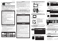
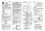
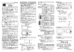
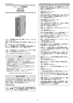
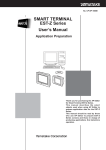
この安全上の注意は、製品を安全に正しくお使いいただき、 あなたや他の人々への危害や財産への損害を未然に防止す るためのものです。安全上の注意は必ず守ってください。 また、内容をよく理解してから本文をお読みください。 EST0240Z05□BX00 1 取り付け金具 W:白モデル B :黒モデル ESTX939FB00 4 1. 各部の名称と機能 POWER LED : 緑、赤、橙の3色で本器の状態を表示します 緑 : 運転中 赤 : エラー発生・ROM書き込み中 橙 : ダウンロード中 緑点滅 : システム画面 液晶表示タッチパネル : STNカラーLCD POWER 取扱説明書 CP-UM-5145 1 本書です お願い 2000 Yamatake Corporation ALL RIGHTS RESERVED 10 9 CH2、CH3、CH4 : RS-485準拠通信 (3チャンネル) 7 6 8 2 3 4 5 RS-232C CH1 : RS-232C準拠通信 24V GND FG 裏ぶた 6 9 ピン 信号名 内 容 番号 1 NC 無接続 2 RD1 受信データ 3 SD1 送信データ 4 ER1 DR6ピンと内部接続 5 SG 信号グランド 6 DR1 ER4ピンと内部接続 7 RS1 送信要求 8 CS1 送信許可 9 NC 接続なし シェル − 接続なし チャン 入出力 ネル CH1 CH1 CH1 入力 出力 CH1 CH1 CH1 出力 入力 DC入出力コネクタ (裏ぶた内部) 電源端子 : DC24V、接地を 接続します ■ 推奨圧着端子 端子 X寸法 ねじ 締付 推奨圧着端子 適用電線 日本圧着端子 mm トルク (JIS規格表示) 断面積mm2 (株)形番(参考) 電源端子 6.4 M3 0.5N・m以下 RAV1.25-3 0.25∼1.65 V1.25-3 通信端子 7.2 M3 1.2N・m以下 X 取扱い上の注意 ・ねじが緩んだときの短絡防止のため、絶縁 スリーブ付き圧着端子を使用してください。 ・取付金具の締付トルク値は上記とは異なり ます。 入出力信号線、電源入力線、接地線は動力機器の電 線系統とは別に敷設してください。 どうしても別に敷設できないときはシールドケーブ ルを使用し、シールド一端を接地してください。 本器の電源入力にはブレーカをつけるか、電流制限 付きのDC電源を使用してください。 4. 外形寸法 適合コネクタ:第一電子工業(株)製17JE-13090-02(D8C2)または相当品 9 10 8 7 6 2 5 4 3 ● CH2:RS-485準拠通信(全・半二重) 端子台 ピン 番号 5 4 3 2 1 信号名 SG RDB2 RDA2 SDB2 SDA2 内 容 チャン 入出力 ネル 信号グランド 受信データ(−) 受信データ(+) 送信データ(−) 送信データ(+) 単位:mm CH2 CH2 CH2 CH2 入力 入力 出力 出力 ● CH3、CH4:RS-485準拠通信(半二重) 端子台 ピン 番号 10 9 8 7 6 信号名 SG DB4 DA4 DB3 DA3 内 容 チャン 入出力 ネル 信号グランド 送受信データ(−) 送受信データ(+) 送受信データ(−) 送受信データ(+) CH4 CH4 CH3 CH3 取扱い上の注意 CH3、CH4はRS-485半二重通信用です。 CH3は、CH2を三菱CPU直結モードに指定したと きには、出力専用(RSA、RSB)端子となります。 ピン 番号 1 5 4 3 2 1 2 3 4 5 信号名 DOVCC DO DOGND DI DIGND 内 容 5. 適合規格 EN50081-2、EN6100-6-2 入出力 入出力 入出力 入出力 ● DC入出力コネクタ CH0 : 赤外線通信ポート 1 この取扱説明書の全部、または一部を無断で複写、また は転載することを禁じます。この取扱説明書の内容を将 来予告なしに変更することがあります。 この取扱説明書の内容については、万全を期しておりま すが、万一ご不審な点や記入もれなどがありましたら、 当社までお申し出ください。 お客様が運用された結果につきましては、責任を負いか ねる場合がございますので、ご了承ください。 5 9 10 本 体 備考 1 内 容 電源正側(+24V) 電源グランド(0V) D種接地 ■ 配線時の注意 ● CH1:RS-232C準拠通信 DSUB 9ピンコネクタ 8 数量 ■ インタフェース信号 7 形番 3. 接 続 6 品名 取扱い上の注意 ねじを締めすぎると破損することがあります。 1 開梱時にご注文の商品の形番、破損の有無、付属品は揃 っているかを確認してください。 万一、異常や間違いがあった場合は、直ちにお買い上げ の販売店までご連絡ください。 梱包箱には以下のものが入っています。 ・強い力や固いもの、または尖ったもので表示部を押さないで ください。表示部が割れたり故障の原因になります。 ・周囲温度、電源電圧などは仕様範囲内でお使いください。仕 様範囲外で使うと故障の原因となります。 ・内部に異物(水、油、配線くず、金属くずなど)やドライバな どを入れないでください。故障の原因となります。 ・通風穴をふさいだり、外部の熱源により温度上昇するような 閉鎖した場所での保管や使用は避けてください。故障の原因 となります。 ・直射日光の当たる場所やほこりの多い場所での保管や使用は 避けてください。 ・衝撃を与えたり、振動の加わる場所での保管や使用は避けて ください。 ・本体、とくに前面に衝撃を与えたりつついて傷をつけないよ うご注意ください。故障の恐れがあります。 ・そりやでこぼこのない平らなパネルに垂直に取り付けてくだ さい。表面保護仕様や温度仕様を満足できなくなり、故障の 恐れがあります。 ・一度はがした保護シートは再使用しないでください。 また、保護シート交換のときは本体側に残った粘着物を取り 除いてください。 ・有機溶剤で本体や表面をふかないでください。 ・不慮の事故により内部データが失われた場合のために、アプ リケーションデータは必ずバックアップしておいてください。 ・落雷時の事故防止のため、屋外配線はしないでください。 ・本器に付いているパッキンが外れて いないことを確認してください 取付金具 ・取付金具が動かなくなった状態から さらに1/2∼1回転だけねじを締め付け 上下各2カ所 てください 5 確認してください 注意 パネルの表面からカットした穴に本器を挿入してく ださい。 付属の取付金具を本体の上下各2カ所の穴に差し込 み、ねじを締め付けて固定してください。 信号名 24V GND FG 取扱い上の注意 ・電源はDC24V専用です。DC24V以外を供給す ると本体が破損します。 ・FG端子は必ず専用接地(D種接地、接地抵抗100 Ω以下)としてください。 4−R3以下 ■ 取り付け 4 ・本製品は、一般機器での使用を前提に、開発・設計・ 製造されております。 とくに、下記のような安全性が必要とされる用途に使 用する場合は、フェールセーフ設計、冗長設計 および 定期点検の実施など、システム・機器全体の安全に配 慮していただいた上でご使用ください。 ・輸送機器(自動車・列車・船舶等)の制御と安全 性に関るユニット ・交通用信号機器 ・防災/防犯装置 ・各種安全装置 ・生命維持を直接の目的としない医療機器 など ・本製品を ・航空機器 ・宇宙機器 ・海底中継機器 ・原子力制御システム ・生命維持のための医療機器、装置 など きわめて高い信頼性を要求される用途には、使用しな いでください。 ・本製品の働きが直接人命に関る用途には、使用しない でください。 ・本製品を安全スイッチ、非常停止スイッチとして使用 しないでください。 ・本製品の使用にあたっては誤動作、破損、動作遅れの 際でも安全な冗長設計を配慮していただいた上でご使 用ください。 ・本器の取り付け、取り外しおよび配線作業のときは必ず電源 を切った状態で行ってください。感電の恐れがあります。 ・分解・改造を行わないでください。内部には高電圧部分があ り、感電の危険性および故障や火災の恐れがあります。 ・腐食性ガス、可燃性ガス、有機溶剤などの雰囲気では使用し ないでください。故障や火災の危険性があります。 ・本器が故障・誤動作した場合も、機械装置が安全に停止する ように、コントローラのシステム設計、リスクアセスメント を実施してください。 ・非常停止回路は、本器とは別に専用のスイッチ・配線で構成 してください。また、安全や機械損傷に影響のあるインター ロックは、本器とは別の専用回路で構成してください。 3 使用上の制限について 196.5± 10 2 スマートターミナルEST240Zをご購入いただき、まこと にありがとうございます。 本書は、安全上の注意と取り付け、結線について説明した ものです。詳しい取り扱いについては別冊の スマートターミナルEST240Z 取扱説明書「ハードウエア 編」CP-SP-1065 (別売品) を用意しています。 24V GND FG 単位:mm 警告 1 スマートターミナル EST240Z 取扱説明書 ■ 電源端子 2. 設置・取り付け ■ パネルカット 126.5± 10 安全上の注意 CP-UM-5145 入出力 出力信号用電源入力 出力信号 出力 出力信号グランド 入力信号 入力 入力信号グランド 適合コネクタ:日本圧着端子(株)製B5B-XH-AM コンタクト別売 〔ご注意〕この資料の記載内容は、お断りなく変更する場合もありますので ご了承ください。 アドバンスオートメーションカンパニー 本 社 〒221-0031 横浜市神奈川区新浦島町1-1-32(ニューステージ横浜) 北海道支店 (011)781-5396 中部支社 (052)238-3037 東北支店 (022)292-2004 関西支社 (06)6881-3383∼4 北関東支店 (048)653-8733 中国支店 (082)222-3982 東京支社 (03)5730-1088 九州支社 (093)953-0631 製品のお問い合わせ、計装のご相談は… コールセンター: 0466-20-2143 〈COMPO CLUBアドレス〉 http://www.compoclub.com/ 〈山武ホームページアドレス〉 http://jp.yamatake.com/ この資料は再生紙を使用しています。 (10) 1999年 8月 初版発行(M) 2003年 4月 改訂7版(W) 4 - User's Manual CP-UM-5145E 1 This manual 9 10 8 7 6 10 2 7 1 6 1 0 126.5 6.4 M3 0.5N m max. Communication terminal 7.2 M3 1.2N m max. RAV1.25-3 0.25 to 1.65 V1.25-3 Handling Precautions •To prevent the short circuit due to loosening of screws, use the crimp type terminal lug with insulator. •Please note that the tightening torque for the metal fittings is different. X ■ Wiring precautions Input/output signal cable, power supply input cable, and grounding cable, should be wired separately from power cables. If routing these cables together cannot be avoided, use a shielded cable, and ground one end of the shield. Attach a circuit breaker to the power supply input of the EST240Z, or use a DC power supply with current limiting. Channel No connection Reception data Transmission data Connected with DR(6-pin) internally Signal ground Connected with ER (4-pin) internally Transmission request Transmission permission No connection No connection CH1 CH1 CH1 CH1 CH1 CH1 Input/ Output Input Output 4. EXTERNAL DIMENSIONS 210 71.2 60.5 144 Unit:mm 126 146.4 Description 140 9 Output Input 196 Recommended connector:DDK Ltd. 17JE-13090-02(D8C2)or equivalent ● CH2:RS-485 based full-/half- duplex communication terminal block 5. APPLICABLE STANDARDS EN50081-2, EN61000-6-2 Specifications are subject to change without notice. 9 10 ESTX939FB00 6 Description Power supply positive side(+24V) Power supply ground(0V) Ground X Tightening Recommended Suitable cross-sectional Parts No. of [mm] Screw torque crimp contact area of the wire J.S.T. MFG CO., Ltd JIS specifications [mm 2 ] Power supply terminal ● CH1:RS-232C based communication DSUB 9pin connector 8 Mounting bracket Terminal 3. CONNECTIONS ■ Interface signals NC RD1 SD1 ER1 SG DR1 RS1 CS1 NC - Input ■ Recommended crimp type terminal lug Overtightening the screws of the four metal fittings can deform or damage the case. 1 2 3 4 5 6 7 8 9 Shell Output •The power supply is 24Vdc only. If other voltage is supplied, the EST240Z will be damaged. •Be sure to connect the FG terminal to the dedicated ground (ground resistance lower than 100Ω). Make sure that the case packing attached to the body is not missing. When the heads of the screws of the four metal fittings are flush with the panel and there is no looseness, turn the screws an extra half to one full turn to ensure that the EST240Z is firmly secured. Pin Signal No. Power supply for the output signal(+) Output signal Output signal ground Input signal Input signal ground Handling Precautions Handling Precautions 5 DOVCC DO DOGND DI DIGND Signal 24V GND FG 24V GND FG Insert the body in the cut-out panel. Use the provided four metal fittings with screws to secure the top and bottom of the EST240Z to the panel. 1 Input/ Output Description ■ Power supply connection 4-R3 max. Four metal fittings for top and bottom holes Signal Recommended connector:J.S.T. MFG CO., LTD B5B-XH-AM (Contact:Separate order) ■ Installation 7 W: White Model B : Black Model 1 0 6 - 196.5 5 1 5 4 3 2 1 Case packing Prevents water and other liquids fromentering the EST240Z. Unit : mm CAUTION • Be careful not to hit and break the front touch panel. Otherwise, the touch panel can be broken and the broken pieces may cause injury. • Use this product within specifications of ambient temperature and power supply voltage as usage out of specification range might cause operational failure. • Prevent debris of wiring or other foreign materials from entering the EST240Z. It may cause trouble or burning the EST240Z. • Do not close the ventilation panel of case. Store this product in a well-ventilated room to avoid exposure to extremely high temperatures caused by external heat sources. Failure to do so might cause the product to malfunction. • Store this product in a location away from dust and exposure to direct sunlight. • Do not store or use this product where it is exposed to direct shocks or vibrations. • Be careful not to give a shock to the body, especially to the front face, or scratch it by something sharp-pointed. Otherwise, malfunction may occur. • Install vertically on a flat panel with no warping or rough surfaces. Failure to do so might result in not meeting specifications for surface protection or temperature, thus causing operational failure. • Do not reuse the panel protective sheet. Remove any adhesives remaining on the product's surfaces before replacing the panel protective sheet. • Do not wipe the body or surfaces of product with organic solvents. • Make a back up of application data to prevent the loss of internal data in the event of an accident. • Do not connect to outdoor wiring, or lightening could cause malfunction. Pin No. 1 2 3 4 5 CH2, CH3, CH4 RS-485 based communication port 2. INSTALLATION AND WIRING ■ Panel cut-out dimensions 4 EST0240Z05✽BX00 • Be sure to turn off the power when you wire, assemble or disassemble the EST240Z. Otherwise, electric shock hazard could occur. • Do not disassemble or remodel this product as the high voltage unit mounted inside might cause an electric shock, fire, or the product to malfunction. • Do not use this product in environments of corrosive or flammable gases or organic solvents as such condi-tions might cause a fire, or the product to malfunction. • Design the controller system and conduct risk assessment in order for the equipment to shut down in case of operational malfunction or failure. • Make an emergency shutdown circuit with a dedicated switch and wiring separate from this product. Make a safety interlock against machinery damage with a dedicated circuit separate from this product. Input/Output Input/Output Input/Output Input/Output DC input/output connector ● Power supply terminals DC input/output (behind the rear cover) For 24Vdc power supply and the grounding 3 Remarks 4 CH1 9pinDSUB connector 24V GND FG 2 Qt'y 3 2 Rear cover 1 Body Model No. WARNING Input/Output CH3 and CH4 are for the RS-485 based half-duplex communication. When CH2 is specified as the direct connection mode for the MITSUBISHI CPU, CH3 becomes an output-only terminal (RSA, RSB). Infrared communication port(CH0) 9 Safety precautions are for ensuring safe and correct use of this product, and for preventing injury to the operator and other people or damage to property. You must observe these safety precautions. Also, be sure to read and understand the content of this User's manual. Pin Signal Description Channel No. 10 SG Signal ground 9 DB4 Transmission/Reception data(-) CH4 8 DA4 Transmission/Reception data(+) CH4 7 DB3 Transmission/Reception data(-) CH3 6 DA3 Transmission/Reception data(+) CH3 Handling Precautions 8 This product has been designed, developed and manufactured for general-purpose application in machinery and equipment. Accordingly, when used in applications outlined below, special care should be taken to implement a fail-safe and/or redundant design concept as well as a periodic maintenance program. • Units for concerning to control and safety of transportation vehicles (auto-mobiles, trains and ships, etc.) • Traffic control systems • Anti-disaster systems, anti-crime systems • Safety equipment • Medical equipment (not specifically designed for life support) Never use this product in applications which require extremely high reliability, such as those outlined below. • Aeronautical machines • Aerospace machines • Submersible repeaters • Nuclear reactor control systems • Life support systems (medical equipment, etc.) Never use this product in applications where human safety may be put at risk. Never use this product as a safety switch or as an emergency stop switch. Special care should be taken to implement a fail-safe and/or redundant design which takes into account the possibility of operational delay, unit damage and malfunction of this product. Name 1 LCD Touch switches are mounted on the display surface. POWER 3 SAFETY PRECAUTIONS UNPACKING 5 Mode indicator lamp Orange :Downloading Green :Operating Red flashing : System error (for example: shortage of work-memory) Red :Error, or in ROM-Write mode Green flashing :System Screen is displayed. Make sure that this User's Manual is handed over to the user before the product is used. Copying or duplicating this User's Manual in part or in whole is forbidden. The information and specifications in this User's Manual are subject to change without notice. Considerable effort has been made to ensure that this User's Manual is free from inaccuracies and omissions. However, if you should find any inaccuracies or omissions, please contact Yamatake Corporation. In no event is Yamatake Corporation liable to anyone for any indirect, special or consequential damages as a result of using this product. 2000 Yamatake Corporation ALL RIGHTS RESERVED RESTRICTIONS ON USE Check the following items when removing the EST240Z from its package: • Check the model No. to make sure that you have received the product that you ordered. • Check the EST240Z for any apparent physical damage. • Check the contents of the package against the Package List to make sure that all accessories are included in the package. After unpacking, handle the EST240Z and its accessories taking care to prevent damage or loss of parts. If an inconsistency is found or the package contents are not in order, immediately contact your dealer. ● CH3, CH4:RS-485 based half-duplex communication terminal block NAMES AND FUNCTIONS OF PARTS RS-232C Thank you for purchasing the Smart Terminal EST240Z. This manual contains information ensuring correct use of the EST240Z. It also provides necessary information for safety precautions, installation and conections. For further details on correct use, read the Smart Terminal EST240Z Installation Manual CPSP-1065E (Sold separately). 1. 5 SMART TERMINAL EST240Z User's Manual REQUEST 4 CP-UM-5145E Pin Signal No. 5 4 3 2 1 SG RDB2 RDA2 SDB2 SDA2 Description Signal ground Reception data(-) Reception data(+) Transmission data(-) Transmission data(+) Channel CH2 CH2 CH2 CH2 Input/ Output Input Input Output Output Advanced Automation Company Totate International Building 2-12-19 Shibuya Shibuya-ku Tokyo 150-8316 Japan URL: http://www.yamatake.com Printed on recycled paper. (04) Printed in Japan. 1st Edition: Issued in Dec. 2000 (W) 4th Edition: Issued in Apr. 2003 (W)