1
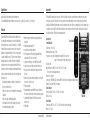
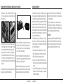
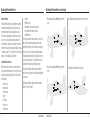
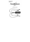
17880
Printed 01/10
©2010 DSM and DSM2 are trademarks or registered trademarks of Horizon Hobby, Inc.
The Spektrum trademark is used with permission of Bachmann Industries, Inc.
Spektrum radios and accessories are exclusively available from Horizon Hobby, Inc.
❚ AR9200 PowerSafe Evolution User Guide
Applications
Important
Giant-scale aircraft / Jets with multiple high-current draw servos
Scale aircraft with multiple high-current draw servos and accessories (e.g. lights, ESCs, air valves, etc.) / Scale helicopters
The PowerSafe Evolution main unit is not a receiver. The PowerSafe Evolution’s main unit is a power distribution center that provides up to 20-amps
current to power your system. Through extensive testing our engineers discovered that mounting the receiver in the typical location in sophisticated
aircraft (an aircraft with many high-current draw servos and/or conductive materials), at the end of the servo and battery leads, is not the optimum location
to provide the clearest RF signal. The AR9200 PowerSafe Evolution uses three remotely mounted receivers that can be optimally placed in your aircraft
providing the best possible RF link in the most demanding conditions.
Features
Spektrum’s AR9200 PowerSafe™ Evolution offers the ultimate solution
for powering high-current draw radio systems. In aircraft with multiple
high-current draw servos (e.g. giant-scale aircraft, jets, etc.), the AR9200
PowerSafe Evolution can provide peak current of up to 20 amps (Each
battery input is regulated independently to 5.9 volts, and each regulator
is capable of handling 10 amps (2 x 10 A)) and offers true dual battery
redundancy and a fail-on soft switch for the ultimate in reliability. By
locating three remote receivers throughout the aircraft, the RF link can
be optimized in even the most demanding aircraft installations that have
significant conductive materials like carbon, stainless steel bypass tubes,
tuned exhausts, etc.
• True dual battery redundancy—each battery is isolated and if one
fails/shorts the other takes over.
• Utilizes three remote receivers for the ultimate RF link in demanding
applications.
• Up to 20 amps peak current handling capability
• SensorSwitch fails-on if the switch is damaged or disconnected
• SensorSwitch indicates battery condition.
1
• Minimum voltage memory indicates any voltage drops that occur
during flight.
• Dual Regulated output voltage (5.9V)
• Large heat sink area for high performance.
• Three voltage indicator LED’s per battery input and three battery
voltage indicator LED’s on the SensorSwitch.
• Support for three battery types: LiPo, NiMH / NiCd, and LiFePo.
• Suppression of any servo feedback currents which might occur.
• Two types of failsafe - Smartsafe (throttle only) and preset failsafe
(all servos)
• QuickConnect - if a power interruption (brownout) occurs the system
reconnects in less than 1/2 second
• Flight Log compatible
• Heavy-duty dual battery inputs with MPX connectors. (Adapters to
EC3 connectors and Deans Ultra connectors are available separately.)
• Compatible with all Spektrum™ and JR® full range radio and
module systems
• 2048 resolution
Spektrum AR9200
Specifications
SensorSwitch
PowerSafe Main unit
Voltage input - 6.0 to 9.0 volts
Minimum operational voltage - 3.5 volts
Peak current - 20 amps Note: Each battery input is regulated to 5.9V, and are each
capable of 10 amps output, for 20 amps combined current.
Resolution - 2048
Main unit Dimensions LxWxH - 3.9 x 2.43 x .78 in (99 x 61.7 x 19.9mm)
Note: Includes mounting lugs and base plate
Weight - 3.0 oz (85 grams)
Connector type - MPX (MPX to EC3 connector and MPX to Deans Ultra connector adapters are available separately.)
Regulator - Dual isolated 10 amp, 5.9V regulators
Remote Receiver
Dimensions LxWxH - 1.02 x .80 x .27 in (25.8 x 20.2 x 6.8mm)
Weight - .2 oz (3 g)
SensorSwitch
Dimmensions LxWxH - 2.55 x .91 x .71 (65 x 23 x 18.1mm) Note: Includes mounting base
Weight - .7 oz (19.8 g)
Spektrum AR9200
Main unit
2
Items Included
Battery Requirements
Using One Battery
• PowerSafe Evolution Main Unit - SPMAR9200
• Three Remote Receivers - SPM9545
• SensorSwitch - PBS9050
• One 24” Remote Receiver Extension - SPM9013
• One 12” Remote Receiver Extension - SPM9012
• One 9” Remote Receiver Extension - SPM9011
• Instruction Manual
• Male/female Bind Plug-SPM6803
Optional Items
• 2150mAh 6.0V NiMH Receiver Pack - SPMB2150NM
2700mAh 6.0V NiMH Receiver Pack - SPMB2700NM
4500mAh 6.0V NiMH Receiver Pack - SPMB4500NM
LiPo Receiver Pack 1350mAh - SPMB1350LP
LiPo Receiver pack 2000mAh - SPMB2000LP
LiPo Receiver Pack 4000mAh - SPMB4000LP
LiPo Receiver Pack 6000mAh - SPMB6000LP
• Flight Log Data Recorder - SPM9540
• 6” Remote Receiver Extension - SPM9010
• 9” Remote Receiver Extension - SPM9011
• 12” Remote Receiver Extension - SPM9012
• 24” Remote Receiver Extension - SPM9013
3
The PowerSafe Evolution allows the option of using one or two battery
packs. When using one battery simply plug the battery into either one of
the two battery connectors (BATT 1 or BATT2).
Using Two Batteries
When using two batteries, the total available capacity equals the sum total
of both batteries e.g., BATT1—2000mAh + BATT2- 2000mAh = a total
capacity of 4000mAh.
Note: MPX to EC3 and Deans Ultra connector adapters are available
separately.
The PowerSafe Evolution offers a true redundant dual battery system with
built in dual voltage regulation. When using two battery packs, each pack
functions independently and is isolated from the other, so that if one pack
should fail (open circuit, short circuit, or become discharged), the other
battery will provide power to operate the system.
• 36” Remote Receiver Extension - SPM9014
• 12” EC3 Extension - SPMEXEC312
• 24” EC3 Extension - SPMEXEC324
• EC3 Battery Connector, Female (2) - EFLAEC302
• MPX to EC3 adapters - SPM6828
• MPX to WS Deans Ultra Adapter - SPM6829
• External LED’s - PBS9070
When using dual batteries it’s important that both batteries be of the same
capacity, number of cells and ideally of the same age and condition. Note:
It’s normal for one battery to discharge slightly more than the other. This
is the nature of a truly redundant isolated battery system. The battery that
has the higher voltage or lower internal resistance will discharge at a faster
rate. Generally the difference is negligible (less than 10%).
Spektrum AR9200
Spektrum AR9200
4
Battery Capacity
Battery Capacity (continued)
It’s important to select a battery(s) that has more than adequate capacity
to provide the necessary flight time. Our staff has been recording in-flight
data to determine typical current consumption of aircraft in flight.
Following are two graphs that illustrate the in-flight current draw of the
radio system.
Note: Current draws may vary depending on your servos, installation and flying style.
File: JasonNoll.FDR Session:All Sessions
18
17
16
15
14
13
12
11
Engine - DA150
Weight - 40 lbs
Flight envelope - Hard 3D
Average current - 2.62 amps
Peak current - 17.8 amps
Milliamps used per 10-minute flight - 435mAh
5
10
9
8
7
6
Recommended Guidelines for Battery Capacity
40-45% Aerobatic aircraft w/ 9-12 high-current servos: 4000–8000mAh
33-35% Aerobatic aircraft w/ 7-10 high-current servos: 3000–6000mAh
25% Quarter Scale Aerobatic aircraft w/ 5-7 high-current servos:
2000–4000mAh
Jets - BVM Super BANDIT, F86, Euro Sport, etc.: 3000–6000mAh
Giant-Scale Jets - BVM Ultra Bandit:4000–8000mAh
5
File: sukhio Session:All Sessions
4
3
7
2
6.5
1
6
0
0
50
100
150
200
250
300
350
400
5.5
450
Seconds
5
PackAmps_A: Min 0.00 Max 17.80 Avg 2.62
4.5
Scale aircraft - The varieties of scale aircraft and the accessories they use
vary tremendously making it difficult to give capacity recommendations for
these types of aircraft. Using the previously mentioned aerobatic guidelines
relative to the size and number of servos used will provide a conservative
capacity for your scale aircraft. As always, check battery charge condition
before each flight.
PackAmps_A
Airplane - 40% YAK
Servos - 9-JR8711’s 1-8317 (throttle)
Batteries - Two 4000mAh 2-cell 7.4-volt LiPo’s
Regulator - None
Note: JR8711’s and 8317’s are rated at a maximum of 6-volt 5-cell use. Using higher
voltages will void the warranty.
PackAmps_A
The following setup is shown as a worst-case scenario indicative of some
aerobatic pilots’ setups. It is not recommended to use this setup without
proper voltage regulation for your servos.
Airplane - 33% Sukhoi
Servos - 7-JR8611’s 1-8317 (throttle)
Batteries - 1- 4000mAh 2-cell 7.4-volt LiPo
Regulator - 6 volt
Engine - DA100
Weight - 26 lbs
Flight envelope - Moderate 3D
Average current - .82 amps
Peak current - 6.92 amps
Milliamps used per 10-minute flight - 137mAh
4
In the example above, the average current was 2.62 amps, which calculates
to 435mAh per 10 minutes (typical flight length). It’s recommended that
only 60% of the available capacity be used to ensure plenty of reserve
battery capacity. In this example using two 4000mAh batteries (8000mAh
total capacity) x 60%= 4800mAh (available usable capacity) divided by the
capacity used per 10-minute flight, 435mAh would allow up to 11 flights, of
10 minutes each.
Spektrum AR9200
3.5
3
2.5
2
1.5
1
0.5
0
0
50
100
150
200
250
300
350
400
450
Seconds
PackAmps_A: Min 0.00 Max 6.92 Avg 0.82
Spektrum AR9200
6
Battery Voltage
IMPORTANT: D0 NOT use a 4-cell 4.8-volt battery to power
the PowerSafe Evolution.
Four-cell 4.8-volt batteries do not provide enough voltage headroom
(additional margin needed) necessary to power the system when heavily
loaded. Under load the system voltage can drop below the voltage system’s
minimum operating voltage threshold (3.5 volts) and cause loss of control.
Installation
Note: When a battery is connected to the PowerSafe Evolution, a low current drain of
less than 1mA occurs even when the switch is turned off. If the system is going to be
stored for any length of time, it’s important that the battery(s) be disconnected from
the PowerSafe Evolution to prevent over discharge.
The PowerSafe Evolution requires all three remote receivers to be plugged
in for the system to operate. Each receiver functions independently and
offers a more secure RF link in difficult environments. The added security
of redundancy should a failure occur outweighs the slight additional weight
and cost penalties.
The PowerSafe Evolution is capable of handling voltages from 6.0 to 10.0
volts. The voltage limitations are generally the servos. The output voltage
to the servos is regulated to 5.9V. Each voltage regulator is capable of
handling 10 amps, for a total of 20 amp maximum current capability.
Be aware that NiMH batteries have a tendency to false peak
when being fast charged. Be especially careful when using NiMH
batteries that they are fully charged and have not false peaked.
Many pilots are using 2-cell LiPo batteries to power their aircraft. LiPo’s
offer greater capacity for their size and weight, and are easier to manage
when charging.
7
Spektrum AR9200
Spektrum AR9200
8
Installing the PowerSafe Evolution Main Unit and SensorSwitch
Installing the Batteries
1. Using four #2 x 1/2” screws or similar(not included), drill 4 1/16” pilot
holes into a ply or hardwood mount, secure the main PowerSafe unit in
the position desired.
Using the guidelines mentioned earlier, select the battery system that best
fits your application and install the battery(s)/regulator(s) in your aircraft.
Connect the battery to the PowerSafe Evolution. Spektrum PowerSafe
batteries are pre-wired with an EC3 connector and require an EC3 to MPX
adapter to plug into the PowerSafe Evolution. It is absolutely essential to
maintain the correct polarity, connecting a battery with reversed polarity
will instantly damage the PowerSafe Evolution’s internal regulators and will
prevent the PowerSafe Evolution from working. The + (positive) mark can
be seen on the PowerSafe Evolution case.
The default battery type setting is for Lithium Polymer, LiPo, 2 cell packs.
If you wish to use 2 cell (7.4V) LiPo packs, you need to make no changes
to the battery type setting. For all other battery types, the battery type must
be set using the following procedure
1. Turn the PowerSafe Evolution on with both batteries if so equipped.
2. Hold the SET button and watch the central LED on the SensorSwitch.
3. The LED will light up, then go out again after a short time.
4. After a few seconds, the LED will emit a short red flash. If using 2 cell
LiPo batteries, and you release the button now, the LiPo battery type will
be selected.
5. If using 5 cell NiMH or NiCd batteries, continue to hold the button until
the LED flashes twice. After the LED flashes twice, release the button to
select NiMH or NiCd battery type.
2. Mount the switch on the side of your aircraft and insert the switch plug
in the SensorSwitch port in the main receiver unit. Make sure to install
the connector as shown with the ribbon cable facing up. In models
with severe vibration, it is recommended to secure the ribbon lead
by at least one additional point to avoid the connector coming loose.
If the connector does fall out in flight, it would have no effect on the
PowerSafe Evolution, but would prevent you from turning the PowerSafe
Evolution off.
Note: The PowerSafe Evolution uses a specifically designed switch. Conventionally
wired switches are not compatible with the PowerSafe Evolution.
9
3. To turn the PowerSafe Evolution receiver on with the SensorSwitch, press and hold
the SET button on the SensorSwitch until the central LED glows red. Now press
buttons 1 and 2 one at a time to turn each on. If you have only 1 battery installed,
you only need to press the button for that battery.
4. To turn the PowerSafe Evolution off with the SensorSwitch, repeat the procedure
for turning the receiver on, by pressing and holding the SET button until the central
LED glows red, then press button 1 and/or button 2.
Note: Once the PowerSafe Evolution has been turned on, it can only be turned off
again by using the SensorSwitch. Intermittent contacts or interruptions in the battery
power cannot cause the PowerSafe Evolution to be switched off permanently.
Spektrum AR9200
Spektrum AR9200
6. If using 2 cell LiFePo batteries, continue to hold the button until the
LED flashes 3 times. After the LED flashes 3 times, release the button to
select LiFePo battery type.
This process generally only takes a few seconds, and is designed to
prevent the danger of accidental changes to the battery type setting. Once
selected, the battery type is permanently stored in the PowerSafe Evolution,
and can only be changed by following the previous procedure.
External LED’s
Optional ultra-bright external LED’s are available (PBS9070) and can be
connected to the PowerSafe Evolution. When mounted externally on the
fuselage side, they will light up and can be seen in flight. The LED’s will
allow you to detect battery problems while the model is in flight.
10
Mounting the Remote Receivers
Antenna Polarization
For optimum RF link performance it’s important that the remote antennas
be mounted in an orientation that allows for the best possible signal
reception when the aircraft is at all possible attitudes and positions.
This is known as antenna polarization. This allows the greatest exposed
visual cross section of the antennas from all aircraft orientations. It is
recommended that one antenna be mounted vertically, one horizontally
in-line with the fuselage and one horizontally perpendicular to the fuselage
(see illustrations on pages 11-12). This covers the X,Y and Z axis offering
superb cross section visibility in all aircraft orientations.
Locating the Remote Receivers
While Spektrum 2.4GHz systems are far more resistant to interference
caused from internal RF generating sources, the remote receivers should
be mounted as far away as practical (typically 4” or greater if possible)
from the following:
• Ignition systems
• Ignition batteries
• Ignition switches
• Engines
• ECU’s pumps
• Electric motors
• Receiver batteries
11
Mounting the Remote Receivers (continued)
• Fuel tanks
• Metal bypass tubes
• High-temperature components like exhaust systems
• Any significant metallic conductive components
• High-vibration areas
The remote antennas should be mounted a minimum of at least 2” apart
from each other as greater antenna separation gives improved path
diversity (RF link performance) in critical environments. In large aircraft
where space is not an issue it is highly recommended that the antennas
be mounted throughout the aircraft as illustrated. Spektrum offers remote
receiver extensions ranging from 6” to 36” allowing the receivers to be
mounted in the most optimum locations throughout the aircraft.
Using double-sided foam tape and tie wraps, mount a minimum of 3
remote receivers in your aircraft as per the illustrations and plug them into
the receiver ports.
• 35% aerobatic plane with single NiMH battery and three remote
receivers
• 40% aerobatic plane with dual LiPo batteries and three remote receivers
• 35% aerobatic plane with dual NiMH batteries and three remote
receivers
• Jet with dual LiPo batteries and three remote receivers
The following are illustrations of typically recommended installations.
Note the remote receiver orientation.
Spektrum AR9200
Spektrum AR9200
12
Plugging in the Servos
Plug the servo leads into the appropriate ports in the PowerSafe Evolution.
You are now ready to bind the system.
The PowerSafe Evolution has dual aileron, rudder, and aux 1 channels
available to operate 2 separate ailerons, rudders, or aux 1 or flap servos.
The dual channels use a linear mix to be used when 2 servos are not
ganged on a single control surface such as 2 servos per aileron. Using
dual servos on a single control surface requires the use of either a
matchbox, program mixing with an open channel/s, or mechanical throw
matching. Failure to match ganged servos throughout the range of motion
on a control surface will result in high amperage drawn by the servos, and
will lead to servo failure. Using an inline current meter such as HAN172 is
recommended to minimize the current draw of the system.
13
Binding
Important - Y-Harnesses and Servo Extensions
When using Y-harnesses or servo extensions, it’s important to use
standard non-amplified Y-harnesses and servo extensions as this
can/will cause the servos to operate erratically or not function at
all. Amplified Y-harnesses were developed several years ago to
boost the signal for some older PCM systems and should not be
used with Spektrum equipment. Note that when converting other
models to Spektrum be certain that all amplified Y-harnesses and/
or servo extensions are replaced with conventional, non-amplified
versions.
The JR PCM Y-Harness with Amplifier (JRPA133) is not compatible
with the AR9200 and should not be used.
Spektrum AR9200
Note: In order for the system to operate, all three remote receivers must be plugged
into the receiver in order for the receivers to bind and link to a transmitter.
It’s necessary to bind the AR9200 to the transmitter so that the AR9200 will
only recognize that specific transmitter, ignoring signals from any other
sources. If the PowerSafe Evolution is not bound to the transmitter, the
system will not operate. During binding the servo’s failsafe positions are
stored.
How To Bind the PowerSafe Evolution
1. With the system hooked up and all remote receivers attached as
described previously, insert the bind plug in the DATA/BIND port in
the PowerSafe Evolution.
Spektrum AR9200
2. Turn on the PowerSafe Evolution with the SensorSwitch. Note that the
LEDs on all receivers should be flashing indicating that the receiver
is ready to bind.
3. Establish the desired failsafe stick positions, normally low throttle
and flight controls neutral.
4. Follow the procedures of your transmitter to enter it into bind mode.
The system will connect within a few seconds. The LEDs on all
receivers should go solid, indicating the system has connected.
5. Remove the bind plug and store it in a convenient place.
6. After you’ve programmed your model, it’s important to rebind the
system so the true low throttle and neutral control surface positions
are programmed.
14
Failsafe Functions
The AR9200 PowerSafe Evolution features two types of failsafe
programming: SmartSafe™ and Preset Failsafe.
SmartSafe
SmartSafe is automatically selected during the standard binding procedure and is
ideal for electric aircraft as well as most gas- and glow-powered aircraft.
How SmartSafe Works
When the Receiver is Powered On without a Transmitter Signal
If you turn on the R291 before you turn on the transmitter, SmartSafe prevents the
throttle from functioning and drives all other channels to their preset positions.
When there is a Loss of Signal in Flight
If the receiver loses the transmitter’s signal in flight, or any other time after a
successful connection has been made, SmartSafe sets the throttle to the position it
was in during the binding process. All other channels hold the positions they were in
at signal loss.
Standard Range Testing
Preset Failsafe
Preset Failsafe allows you to set the specific control positions for all channels to go
to should you encounter signal loss in flight or at any other time after a successful
connection has been made. Preset Failsafe is typically used to prevent “fly aways”
in high-performance models by deploying spoilers in sailplanes or putting gas- and
glow-powered models into a slight turn at reduced throttle.
How to Program Preset Failsafe Settings
Insert the bind plug and power on the receiver. When the receiver’s LED lights begin
to blink indicating it is in bind mode, remove the bind plug before binding the
transmitter to the receiver. The LED lights on the receiver continue to blink. Move
your transmitter’s control sticks and switches to the desired Preset Failsafe positions
then turn it on in bind mode. The system should connect in less than 15 seconds.
How to Program the Receiver for SmartSafe
Simply move the throttle to a desired in-flight failsafe position (typically this is all the
way back) and bind the receiver to the transmitter. Leave the bind plug in the receiver
during the entire binding process. Remove the bind plug only after a connection has
been made and the controls are functioning normally.
15
Spektrum AR9200
Before each flying session, and especially with a new model, it’s
important to perform a range check. All Spektrum aircraft transmitters
incorporate a range testing system, which reduces the output power
allowing a range check.
Range Testing
1. With the model resting on the ground, stand 30 paces (approx. 90
feet/28 meters) away from the model.
2. Face the model with the transmitter in your normal flying position and
put your transmitter into range test mode. This causes reduced power
output from the transmitter.
3. You should have total control of the model in range test mode at
30 paces (90 feet/28 meters).
4. If control issues exist, call Horizon Product Support for further
assistance.
United States: 1-877-504-0233
European Union: +44 1279 641 097 (United Kingdom)
+49 4121 46199 66 (Germany)
Spektrum AR9200
30 paces (90 feet/28 meters)
Press and hold the bind button
16
Advanced Range Testing Using a Flight Log
The Standard Range Testing procedure is recommended for most sport
aircraft. For sophisticated aircraft that contain significant amounts of
conductive materials (e.g. turbine powered jets, some types of scale
aircraft, aircraft with carbon fuselages, etc.), the following advanced range
check will confirm that all remote receivers are operating optimally and
that the installation (position of the receivers) is optimized for the specific
aircraft. This Advanced Range Check allows the RF performance of each
remote receiver to be evaluated and to optimize the locations of each
individual remote receiver.
Advanced Range Testing
1. Plug a Flight Log into the Bind/Data port in the AR9200 and turn on the
system (Tx and Rx).
2. Advance the Flight Log until frame losses are displayed by pressing the
button on the Flight Log.
3. Have a helper hold your aircraft while observing the Flight Log data.
4. Standing 30 paces away from the model, face the model with the
transmitter in your normal flying position and put your transmitter into
range test mode. This causes reduced power output from the transmitter.
5. Have your helper position the model in various orientations (nose up,
nose down, nose toward the Tx, nose away from the Tx, etc.) while
your helper watches the Flight Log noting any correlation between
the aircraft’s orientation and frame losses. Do this for 1 minute. The
17
Flight Log
timer on the transmitter can be used here. For giant-scale aircraft it’s
recommended that the airplane be tipped up on its nose and rotated 360
degrees for one minute then the data recorded. Next place the airplane
on its wheels and do a second test rotating the aircraft in all directions
for one minute.
6. After one minute, a successful range check will have less than ten
recorded frame losses. Scrolling the Flight Log through the antenna
fades (A, B, L,) allows you to evaluate the performance of each receiver.
Antenna fades should be relatively uniform. If a specific antenna is
experiencing a high degree of fades then that antenna should be moved
to a different location.
7. A successful advanced test will yield the following:
H - 0 holds
F - less than 10 frame losses
A, B, L - Frame losses will typically be less than 100. It’s
important to compare the relative frame losses. If a particular
receiver has a significantly higher frame loss value (2 to 3X)
then the test should be redone and if the same results occur,
move the offending receiver to a different location.
Spektrum AR9200
Spektrum’s Flight Log (SPM9540) is compatible with the AR9200 PowerSafe
Evolution. The Flight Log displays overall RF link performance as well as
the individual internal and external receiver link data. Additionally it displays
receiver voltage.
Using the Flight Log
After a flight and before turning off the receiver or transmitter, plug the Flight
Log into the Data port on the PowerSafe. The screen will automatically
display voltage e.g. 6v2= 6.2 volts.
Note: When the voltage reaches 4.8 volts or less, the screen will flash indicating
low voltage.
Press the button to display the following information:
A - Antenna fades on antenna A
Spektrum AR9200
B - Antenna fades on antenna B
L - Antenna fades on the left antenna
F - Frame loss
H - Holds
Antenna fades—represents the loss of a bit of information on that specific
antenna. Typically it’s normal to have as many as 50 to 100 antenna fades
during a flight. If any single antenna experiences over 500 fades in a single
flight, the antenna should be repositioned in the aircraft to optimize the RF link.
Frame loss—represents simultaneous antenna fades on all attached receivers.
If the RF link is performing optimally, frame losses per flight should be less
than 20. The antenna fades that caused the frame loss are recorded and will be
added to the total antenna fades.
A Hold occurs when 45 consecutive frame losses occur. This takes about one
second. If a hold occurs during a flight, it’s important to reevaluate the system,
moving the antennas to different locations and/or checking to be sure the transmitter and receivers are all working correctly. The frame losses that led to the
hold are not added to the total frame losses.
Note: A servo extension can be used to allow the Flight Log to more conveniently be
plugged in without having to remove the aircraft’s hatch or canopy. On some models, the
Flight Log can be plugged in, attached and left on the model using double-sided tape.
This is common with helicopters, mounting the Flight Log conveniently to the side frame.
18
QuickConnect™ with Brownout Detection
The AR9200 Evolution features QuickConnect with Brownout Detection.
Should a power interruption occur (brownout), the system will reconnect
immediately when power is restored and the LEDs on each connected
receiver will flash indicating a brownout (power interruption) has occurred.
Brownouts can be caused by an inadequate power supply (weak battery or
regulator), a loose connector, a bad switch, an inadequate BEC when using
an electronic speed controller, etc. Brownouts occur when the receiver
voltage drops below 3.2 volts thus interrupting control as the servos and
receiver require a minimum of 3.2 volts to operate.
How Brownout Detection Works
When the receiver voltage drops below 3.2 volts the system drops out
(ceases to operate). When power is restored, the receivers will immediately
attempt to reconnect to the last two frequencies they were connected to.
If the two frequencies are present (the transmitter was left on) the system
reconnects, typically about 4ms. The receivers will then blink indicating
a brownout has occurred. If at any time the receiver is turned off then
back on and the transmitter is not turned off, the receivers will blink as a
power interruption was induced by turning off the power to the receiver.
In fact this simple test (turning the receiver off then on) will allow you to
determine if your system’s brownout detection is functioning.
19
Note: If a brownout occurs in-flight it is vital that the cause of the brownout be
determined and corrected. QuickConnect and Brownout Detection are designed to
allow you to safely fly through most short duration power interruptions. However, the
root cause of these interruptions must be corrected before the next flight to prevent
catastrophic safety issues.
The AR9200 PowerSafe Evolution features a minimum voltage memory that can be
used to evaluate your aircraft and the battery packs. The minimum voltage memory
shows you the extent to which the battery voltage dropped during the last flight due to
the control surfaces jamming, the model has stiff linkages, or it has batteries that fade
under load. It is a good idea to make it part of your routine to check the minimum
voltage memory after every flight, this allows you to find problems with the model
or batteries before the next flight. To check the minimum voltage, after a flight, press
both SensorSwitch battery 1 and 2 buttons. The 3 battery LED’s will indicate the
lowest voltage level that occurred during the flight. The minimum voltage memory
does not record short duration voltage drop outs, only those voltage drops which last
longer than one second.
Spektrum AR9200
Spektrum AR9200
20
Frequently Asked Questions on Spektrum 2.4GHz
Your DSM2 equipped 2.4GHz system is intuitive to operate, functioning
nearly identically to FM systems. Following are a few common questions
from customers:
Q: After I’ve bound the receiver to my transmitter, which do I
turn on first when I want to fly?
A: Either one. Every DSM 2.4GHz transmitter has a GUID (Globally
Unique Identifier) code imbedded in its signal. When you bind a
DSM receiver to your transmitter, this GUID code is stored in the
receiver. If you turn the receiver on before the transmitter, you don’t
have to worry about it responding to another transmitter. The receiver
will inhibit throttle output and drive all controls to preset positions
while it waits for a signal from the transmitter with the same GUID
code it has stored.
If a DSM transmitter is turned on first you can expect it to connect
within 6 seconds of powering on the receiver.
Q: Sometimes the system takes longer to connect or doesn’t
connect at all. Why?
Frequently Asked Questions on Spektrum 2.4GHz (continued)
close to the receiver (within 4 feet) or near metal objects it may detect
its own reflected 2.4GHz energy as “noise”. This can delay or prevent
connection.
If this happens make sure you are a sufficient distance from metal
objects and the receiver itself before you power up and try again.
Q: Is it true that DSM systems are less tolerant of low voltage?
A: All DSM receivers require at least 3.5V to operate normally. Most
servos cease to operate below 3.8V. Using multiple high-voltage
servos, however, with an inadequate power supply can allow voltage
to momentarily drop below 3.5V. This will cause the receiver to
“brown out” and reconnect.
All recently manufactured JR and Spektrum DSM receivers feature
QuickConnect technology that will reconnect the system within
a quarter of a second should a brown out occur. In addition, the
receiver’s LED will flash, indicating a brown out has occurred. If after
landing you notice your DSM receiver’s LED is flashing make sure
you have adequate power before you fly again.
Q: Sometimes when I power on my DSM system I notice the
receiver won’t connect and it needs to be rebound to the
transmitter. Can this happen in flight?
A: No. A DSM receiver cannot be unbound from its transmitter without
specific action by the user.
You can accidentally unbind a receiver by inadvertently pressing
the bind button on your transmitter when you turn it on. This will
cause the transmitter to go into bind mode. If this happens and the
transmitter doesn’t detect a binding signal from the receiver it can
cause the receiver to be unbound. Some transmitter stands can cause
the bind button to be depressed during power up, but these instances
are extremely rare.
If your system fails to connect, chances are much greater that it’s the
result of one of the following conditions and not because the receiver
is unbound.
1. You’ve selected the wrong model memory.
2. The transmitter is too close to conductive material to connect
(see FAQ #2).
Q: How important is it that I test my system using a Spektrum
Flight Log?
A: All 2.4GHz signals, not just DSM, are affected by proximity to
conductive materials such as carbon fiber or metal. Few RTF and ARF
sport airplanes or helicopters use enough of these kinds of materials
for it to be an issue. If, however, you’re flying a sophisticated model
that uses a lot of conductive materials in its construction, a Flight
Log can be helpful. The information it collects when you fly will
help you determine the optimum location for your receiver(s) so
you can minimize the effects of these materials on your signal
performance. For more details on the Flight Log and how it works,
visit SpektrumRC.com.
A: In order for a DSM system to connect, the receiver must receive a
large number of uninterrupted signal packets from the transmitter.
This process takes just a few seconds, but if the transmitter is too
21
Spektrum AR9200
Spektrum AR9200
22
Tips for Getting the Most from your PowerSafe System
Flight Log
The optional Flight Log is highly recommended. The Flight Log can be used to
test the battery system using the built-in voltmeter and applying a load to the
servos/control surfaces. The voltage should never drop below the rated voltage
(5.9 volts) even under a heavy load.
When the system is first installed it is highly recommend that an advanced
range check be performed. (See advanced range check on page 18.) If any
receiver is performing less than optimally (higher than normal fades) that
receiver should be repositioned and the advanced range test repeated until low
fades are recorded.
During first flights with sophisticated airplanes (significant conductive
materials onboard, many high-current draw servos, carbon construction, etc.),
it’s a good practice to keep your first flight in close then confirm
the RF link performance using the Flight Log to determine the performance of
each attached receiver. Extend the distance on subsequent flights
and record the Flight Log data confirming that all systems are
performing properly.
Storing Your System
If the system will be stored for more than two weeks, it’s important that
the battery be disconnected from the PowerSafe Evolution. The PowerSafe
Evolution draws a small amount of current (less than 1ma) even when the
switch is turned off and the battery will drain and could become damaged if left
23
Warranty Period:
attached for an extended period. This is especially important when using LiPo
batteries as irreversible damage could occur to your batteries.
Using Nickel-Metal Hydride Batteries
The latest generation of NiMH batteries incorporates a new chemistry mandated
to be more environmentally friendly. These batteries, when charged with peak
detection chargers have tendencies to false peak (not fully charge) repeatedly.
These include all brands of NiMH batteries. If using NiMH packs be especially
cautious when charging making absolutely sure that the battery is fully
charged. It is recommended that a fast charge with a meter that monitors the
input mAh be used and that the expected charge capacity is reached during
charge.
Safety Precautions:
This is a sophisticated hobby Product and not a toy. It must be operated with
caution and common sense and requires some basic mechanical ability. Failure
to operate this Product in a safe and responsible manner could result in injury
or damage to the Product or other property. This Product is not intended for
use by children without direct adult supervision. The Product manual contains
instructions for safety, operation and maintenance. It is essential to read and
follow all the instructions and warnings in the manual, prior to assembly, setup
or use, in order to operate correctly and avoid damage or injury.
Spektrum AR9200
Exclusive Warranty- Horizon Hobby, Inc., (Horizon) warranties that the Products purchased
(the “Product”) will be free from defects in materials and workmanship for a period of 1 year
from the date of purchase by the Purchaser.
1 Year Limited Warranty
Horizon reserves the right to change or modify this warranty without notice and
disclaims all other warranties, express or implied.
(a) This warranty is limited to the original Purchaser (“Purchaser”) and is not transferable.
REPAIR OR REPLACEMENT AS PROVIDED UNDER THIS WARRANTY IS THE EXCLUSIVE
REMEDY OF THE PURCHASER. This warranty covers only those Products purchased from
an authorized Horizon dealer. Third party transactions are not covered by this warranty. Proof
of purchase is required for warranty claims. Further, Horizon reserves the right to change or
modify this warranty without notice and disclaims all other warranties, express or implied.
(b) Limitations- HORIZON MAKES NO WARRANTY OR REPRESENTATION, EXPRESS
OR IMPLIED, ABOUT NON-INFRINGEMENT, MERCHANTABILITY OR FITNESS FOR A
PARTICULAR PURPOSE OF THE PRODUCT. THE PURCHASER ACKNOWLEDGES THAT
THEY ALONE HAVE DETERMINED THAT THE PRODUCT WILL SUITABLY MEET THE
REQUIREMENTS OF THE PURCHASER’S INTENDED USE.
(c) Purchaser Remedy- Horizon’s sole obligation hereunder shall be that Horizon will, at
its option, (i) repair or (ii) replace, any Product determined by Horizon to be defective. In
the event of a defect, these are the Purchaser’s exclusive remedies. Horizon reserves the
right to inspect any and all equipment involved in a warranty claim. Repair or replacement
decisions are at the sole discretion of Horizon. This warranty does not cover cosmetic
damage or damage due to acts of God, accident, misuse, abuse, negligence, commercial use,
or modification of or to any part of the Product. This warranty does not cover damage due
to improper installation, operation, maintenance, or attempted repair by anyone other than
Horizon. Return of any goods by Purchaser must be approved in writing by Horizon
before shipment.
Spektrum AR9200
Damage Limits:
HORIZON SHALL NOT BE LIABLE FOR SPECIAL, INDIRECT OR CONSEQUENTIAL
DAMAGES, LOSS OF PROFITS OR PRODUCTION OR COMMERCIAL LOSS IN ANY WAY
CONNECTED WITH THE PRODUCT, WHETHER SUCH CLAIM IS BASED IN CONTRACT,
WARRANTY, NEGLIGENCE, OR STRICT LIABILITY. Further, in no event shall the liability of
Horizon exceed the individual price of the Product on which liability is asserted. As Horizon
has no control over use, setup, final assembly, modification or misuse, no liability shall
be assumed nor accepted for any resulting damage or injury. By the act of use, setup or
assembly, the user accepts all resulting liability.
If you as the Purchaser or user are not prepared to accept the liability associated with the
use of this Product, you are advised to return this Product immediately in new and unused
condition to the place of purchase.
Law: These Terms are governed by Illinois law (without regard to conflict of law principals).
Warranty Services
Questions, Assistance, and Repairs:
Your local hobby store and/or place of purchase cannot provide warranty support or repair.
Once assembly, setup or use of the Product has been started, you must contact Horizon
directly. This will enable Horizon to better answer your questions and service you in the event
that you may need any assistance. For questions or assistance, please direct your
email to [email protected], or call 877.504.0233 toll free to speak to a
Product Support representative.
Inspection or Repairs
If this Product needs to be inspected or repaired, please call for a Return Merchandise
Authorization (RMA). Pack the Product securely using a shipping carton. Please note that
original boxes may be included, but are not designed to withstand the rigors of shipping
without additional protection. Ship via a carrier that provides tracking and insurance for lost
or damaged parcels, as Horizon is not responsible for merchandise until it arrives and is
accepted at our facility. A Service Repair Request is available at www.horizonhobby.com on the
“Support” tab. If you do not have internet access, please include a letter with your complete
name, street address, email address and phone number where you can be reached during
24
business days, your RMA number, a list of the included items, method of payment for any
non-warranty expenses and a brief summary of the problem. Your original sales receipt must
also be included for warranty consideration. Be sure your name, address, and RMA
number are clearly written on the outside of the shipping carton.
Warranty Inspection and Repairs
To receive warranty service, you must include your original sales receipt verifying the proofof-purchase date. Provided warranty conditions have been met, your Product will be repaired
or replaced free of charge. Repair or replacement decisions are at the sole
discretion of Horizon Hobby.
Country of Purchase
Horizon Hobby
Address
Phone Number/ Email
United States
Horizon Service Center
4105 Fieldstone Rd
Champaign, Illinois
61822 USA
877-504-0233
4105 Fieldstone Rd
Champaign, Illinois
61822 USA
877-504-0233
Units 1-4 Ployters Rd
Staple Tye
Harlow, Essex
CM18 7NS
United Kingdom
+44 (0) 1279 641 097
(Electronics and engines)
Horizon Product Support
(All other products)
United Kingdom
Germany
Non-Warranty Repairs
Should your repair not be covered by warranty the repair will be completed and payment will
be required without notification or estimate of the expense unless the expense exceeds 50%
of the retail purchase cost. By submitting the item for repair you are agreeing to payment
of the repair without notification. Repair estimates are available upon request. You must
include this request with your repair. Non-warranty repair estimates will be billed a minimum
of ½ hour of labor. In addition you will be billed for return freight. Please advise us of your
preferred method of payment. Horizon accepts money orders and cashiers checks, as well
as Visa, MasterCard, American Express, and Discover cards. If you choose to pay by credit
card, please include your credit card number and expiration date. Any repair left unpaid or
unclaimed after 90 days will be considered abandoned and will be disposed of accordingly.
Please note: non-warranty repair is only available on electronics and model engines.
France
Horizon Hobby Limited
Declaration of Conformity
[email protected]
(in accordance with ISO/IEC 17050-1) [email protected]
[email protected]
Horizon Technischer Service Hamburger Str. 10
25335 Elmshorn
Germany
+49 4121 46199 66
Horizon Hobby SAS
+33 (0) 1 60 47 44 70
14 Rue Gustave Eiffel
Zone d’Activité du Réveil Matin
91230 Montgeron
Compliance Information for the European Union
[email protected]
No. HH20100323
Product(s):
Item Number(s): Spektrum AR9200 Receiver
SPMAR9200
Equipment class:
1
Instructions for Disposal of WEEE by Users in the European Union
This product must not be disposed of with other waste. Instead, it is the user’s
responsibility to dispose of their waste equipment by handing it over to a
designated collection point for the recycling of waste electrical and electronic
equipment. The separate collection and recycling of your waste equipment at the time of
disposal will help to conserve natural resources and ensure that it is recycled in a manner that
protects human health and the environment. For more information about where you can drop
off your waste equipment for recycling, please contact your local city office, your household
waste disposal service or where you purchased the product.
The object of declaration described above is in conformity with the requirements of the
specifications listed below, following the provisions of the European R&TTE directive 1999/5/EC:
EN 301 489-1, 301 489-17 General EMC requirements for Radio equipment
FCC Information
Signed for and on behalf of:
Horizon Hobby, Inc.
Champaign, IL USA
March 23, 2010
Caution:
This device complies with part 15 of the FCC rules. Operation is subject to the following
two conditions: (1) This device may not cause harmful interference, and (2) this device must
accept any interference received, including interference that may cause undesired operation.
Changes or modifications not expressly approved by the party responsible for compliance
could void the user’s authority to operate the equipment.
Steven A. Hall
Vice President
International Operations and Risk Management
Horizon Hobby, Inc.
This product contains a radio transmitter with wireless technology which has been tested and
found to be compliant with the applicable regulations governing a radio transmitter in the
2.400GHz to 2.4835GHz frequency range.
25
Spektrum AR9200
Spektrum AR9200
26