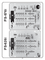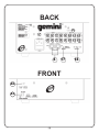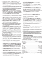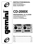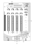
1
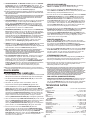
OPERATIONS MANUAL
BEDIENUNGSHANDBUCH
MANUAL DEL OPERADOR
MANUEL D’INSTRUCTIONS
PS-626i/676i
PROFESSIONAL MIXER
PROFESSIONNELLER VORVERSTÄRKERMISCHPULT
MEZCLADOR PARA EL PROFESIONAL
MÉLANGEUR LE PROFESSIONNEL
MULTI LANGUAGE INSTRUCTIONS:
English......................................................................................................Page 4
Deutsch....................................................................................................Page 6
Español.....................................................................................................Page 8
Francais.................................................................................................Page 10
(1)
(2)
35
13
34
25
29
26
28
30
27
24
23
22
20
21
20
20
19
18
21
19
19
40
21
18
18
41
37
36
39
38
31
32
33
36
36
3
PS-626i
16
2
47
35
13
53
46
34
25
45 45 45
26
51
28
50
27
24
23
22
20
21
20
20
19
18
21
19
19
40
21
18
18
41
52
36
36
36
36
38
31
32
33
39
3
PS-676i
48
44
16
2
BACK
15
1
5
6
7
8
9
10 11 12
5
6
7
8
9
10 11 12
4
17
FRONT
42
43
(3)
14
INTRODUCTION:
THE GROUND LIFT SWITCH:
Depending on your system configuration, applying the ground
sometimes creates a quieter signal path. Sometimes “lifting” the ground
eliminates loops and hum to create a quieter signal path.
Congratulations on purchasing a GEMINI Platinum Series model PS-626i
or PS-676i Mixer. This state-of-the-art mixer is backed by a three year
warranty, excluding crossfader and channel slides. Prior to use, we
suggest that you carefully read all the instructions.
1. Listen to the system with the unit ON, without music, and with the
ground “applied”. GROUND LIFT SWITCH (17) should be to the left.
FEATURES:
•
•
•
•
•
•
•
•
Cut Feature for Low, Mid and High of each channel
3 Stereo channels (3 Phono, 3 Line and 1 Mic)
1/4" DJ Mic jack
Low, Mid, High and Gain controls on each channel
Beat indicators
Master, Booth and Record outputs
Dual mode display (Left & Right output or Channel 2 and Channel 3)
Push button cueing with Cue/Program pan control
2. Turn power OFF before moving the GROUND LIFT SWITCH (17).
3. Now, “lift” the ground by moving the GROUND LIFT SWITCH (17) to the
right. Turn the power back ON and listen to determine which position
provides a signal free of background noise and hum.
NOTE: KEEP GROUND LIFT IN THE GROUND “APPLIED” OR LEFT POSITION IF NOISE LEVEL
REMAINS THE SAME IN EITHER POSITION.
CAUTION: DO NOT TERMINATE THE AC GROUND ON THE POWER CABLE. TERMINATION OF
THE AC GROUND CAN BE HAZARDOUS.
PS-676i:
• Digital sampler
OPERATION:
CAUTIONS:
1. POWER ON: Once you have made all the equipment connections to
your mixer, press the POWER SWITCH (2). The power will turn on and
the POWER LED (3) will glow RED.
1. All operating instructions should be read before using this equipment.
2. To reduce the risk of electrical shock, do not open the unit. There are
NO USER REPLACEABLE PARTS INSIDE. Please refer servicing to a
qualified GEMINI Sound Products service technician.
2. CHANNEL 1: The GAIN (18), HIGH (19), MID (20), and LOW (21).
Controls allows you to fully adjust the selected source. SWITCH (22)
allows you to select either the MIC (13) or the PHONO 1/LINE 1 (12)
input. The CHANNEL (25) slide controls the output level of this channel.
In the USA: if you experience problems with this unit,
please call 1 (732) 738-9003 for GEMINI Customer Service.
Do not attempt to return this equipment to your dealer.
3. MAIN CHANNEL SECTION: To assign an input source to a channel,
first set the PHONO/LINE (23,24) switches to their appropriate
positions. To make the proper adjustments to your music, set the GAIN
(18), HIGH (19), MID (20), and LOW (21) controls and position the
CHANNEL (26,27) slide.
3. Do not expose this unit to direct sunlight or to a heat source such as a
radiator or stove.
4. This unit should be cleaned only with a damp cloth. Avoid solvents or
other cleaning detergents.
PLEASE NOTE: THERE IS LOW, MID AND HIGH EQUALIZATION FOR EACH CHANNEL WITH AN
EXTREMELY WIDE RANGE OF ADJUSTMENT.
SUGGESTION: YOU CAN USE THE CUT FEATURES ON EACH CHANNEL TO REMOVE LOW, MID
AND/OR HIGH RANGE TO CREATE SPECIAL EFFECTS.
5. When moving this equipment, it should be placed in its original carton
and packaging. This will reduce the risk of damage during transit.
Your Gemini mixer comes with an RG-45 PRO (RAIL GLIDE™) DUALRAIL CROSSFADER. RAIL GLIDE™ Crossfaders have internal dual
stainless steel rails that allow the slider to ride smoothly and accurately
from end to end. Gemini replacement Crossfaders are available in
three varieties: the RG-45 PRO (RAIL GLIDETM) Dual-Rail Crossfader;
the RF-45, which has a 45mm travel from side-to-side; and the PSF-45,
which features a special “curve” designed for scratch mixing.The
CROSSFADER in your unit is removable and, should the need arise, can
easily be replaced by following these instructions.
6. DO NOT EXPOSE THIS UNIT TO RAIN OR MOISTURE.
7. DO NOT USE ANY SPRAY CLEANER OR LUBRICANT ON ANY
CONTROLS OR SWITCHES.
CONNECTIONS:
1. Before plugging in the power cord, make sure that the VOLTAGE
SELECTOR (1) switch is set to the correct voltage.
NOTE: THIS PRODUCT IS DOUBLE INSULATED AND IS NOT INTENDED TO BE GROUNDED.
2. Make sure that the POWER (2) switch is in the off position. The POWER
LED (3) will be off.
3. The PS-626i/676i is supplied with 4 sets of output jacks.
• The 1/4" BALANCED OUTPUT (4) jacks are used to connect to your
main amplifier using standard balanced cables. We recommend using
balanced amp outputs if the cables to your amplifier are 25 feet or more.
• The MASTER OUTPUT (5) (RCA type) jacks are unbalanced and used
to connect to your main amplifier.
• The BOOTH OUTPUT (6) (RCA type) jacks allow you to hook up an
additional amplifier.
• The REC OUTPUT (7) (RCA type) jacks can be used to connect the
mixer to the record input of your recorder enabling you to record your mix.
5. On the rear panel are 2 stereo PHONO (8, 10) inputs, 2 stereo LINE
(9, 11) inputs and 1 stereo PHONO 1/LINE 1 (12) input. The PHONO/LINE
(14) switch enables you to set the input to PHONO 1/ LINE 1 (12). The
phono inputs will accept only turntables with a magnetic cartridge. A
GROUND (15) screw to ground your turntables is located on the rear
panel. The stereo line inputs will accept any line level input such as a
CD player, a cassette player, etc.
6. Headphones can be plugged into the front panel mounted HEADPHONE
(16) jack.
1. Unscrew the outside FADER PLATE SCREWS (B).
• Do not touch INSIDE SCREWS (C).
2. Carefully remove old Crossfader and unplug CABLE (D).
3. Plug new Crossfader into CABLE (D) and place back into mixer.
4. Screw Crossfader to mixer with FADER PLATE SCREWS (B).
4. CROSSFADER SECTION: The CROSSFADER (28) allows the mixing of
one source into another. The left side of the CROSSFADER (28) is
CHANNEL 2 and the right side is CHANNEL 3.
5. BEAT INDICATORS: Each side of the CROSSFADER (28) has its own
BEAT INDICATOR (29, 30). They flash at the low frequency peak level
allowing you to match the beats visually. BEAT INDICATOR (29) will
reflect the beat of CH2 and BEAT INDICATOR (30) will do the same for CH3.
6. OUTPUT CONTROL SECTION: The level of the MASTER (5) output is
controlled by the MASTER (31) control. The BALANCE (32) control will
allow the Amp Out signal to be balanced between the left and right
speakers. The BOOTH (33) control adjusts the level of the BOOTH
OUTPUT (6).
(4)
HINT: BOOTH OUTPUT (6) IS USED BY SOME DJS TO RUN MONITOR SPEAKERS IN THE DJ
BOOTH. YOU CAN ALSO USE IT AS A SECOND ZONE OR AMP OUTPUT.
NOTE: THE RECORD OUT (7) HAS NO LEVEL CONTROL. THE LEVEL IS SET BY THE CHANNEL
SLIDES AND THE GAIN CONTROLS OF THE SELECTED CHANNEL. TONAL QUALITIES ARE
SET BY THE LOW, MID AND HIGH CONTROLS OF THAT SAME CHANNEL.
2. When the MODE SELECTOR (44) is in the SINGLE or REPEAT mode, the
SAMPLER REC/PLAY LEVEL (46) control acts as a Sampler Level
Control.
7. TALKOVER SECTION: The purpose of the TALKOVER SECTION is to
allow the program playing to be muted so that the MIC (13) can be
heard above the music. When the TALKOVER (34) button is pushed, the
TALKOVER INDICATOR (35) will glow and the volume of all sources
except the MIC (13) or whatever is connected to the PHONO 1/LINE 1
(12) input are reduced by 16 dB.
3. Tapping the START/STOP (48) button with the MODE SELECTOR (44) in
the SINGLE position will cause the sampler to playback one time (the
SAMPLER INDICATOR (49) will illuminate GREEN). Every push of the
START/STOP (48) button will restart the sample from the beginning.
Rapid pressing of the START/STOP (48) button will cause a stuttering
effect. Once the sample has started playback and the START/STOP
(48) button is not pushed a second time, the sample will play to the end
and then stop (the SAMPLER INDICATOR (49) will illuminate turn off).
8. CUE SECTION: By connecting a set of headphones to the HEADPHONE
(16) jack, you can monitor any or all of the channels. Select the correct
CUE (36) button or buttons and their respective CUE LED (37) indicators
will glow. Use the CUE LEVEL (38) control to adjust the headphone
volume without effecting the overall mix. By sliding the CUE PGM PAN
(39) control to the left you will be able to monitor the assigned cue
signal. Sliding to the right will monitor the PGM (program) output.
4. Tapping the START/STOP (48) button with the MODE SELECTOR (44) in
the REPEAT position will cause the sample to continuously play over and
over (the SAMPLER INDICATOR (49) will illuminate GREEN). The
START/STOP (48) button will act as an on/off switch. The first push will
start the sample, the second push will stop it.
9. DISPLAY: The peak hold, dual function DISPLAY (40) indicates either
the MASTER (5) output left and right levels or the CHANNEL 2 and
CHANNEL 3 levels. You can choose the option you want by pressing
the DISPLAY (41) button.
1. With the ROBO PLAY (50) button in the OFF position (the ROBO PLAY
INDICATOR (51) will be OFF) and the MODE SELECTOR (44) switch in
either the SINGLE or REPEAT mode, pressing the START/STOP (48) will
cause the sample to play along with the signal going through the mixer.
NOTE: WHEN THE DISPLAY (40) IS IN THE CHANNEL 2/CHANNEL 3 DISPLAY MODE, BY
ADJUSTING THE INDIVIDUAL CHANNEL GAIN AND TONE CONTROLS, YOU CAN
INCREASE OR DECREASE THE SIGNAL TO MATCH THE OTHER CHANNEL’S SIGNAL. THE
CHANNEL SLIDES AND CROSSFADER HAVE NO EFFECT ON THE DISPLAY READINGS.
2. When the ROBO PLAY (50) button is in the ON position (the ROBO PLAY
INDICATOR (51) illuminates RED), starting the sampler mutes the signal
going through the mixer. When the sample ends, the signal automatically
turns back on.
10. The CROSSFADER CURVE SWITCH (42) allows you to adjust the kind
of curve the crossfader has. Move switch to the “sharp” position to
make the curve steep and cutting (perfect for scratching ). Move switch
to the “gradual” position to make the curve gradual and gentle. The
CROSSFADER REVERSE SWITCH (43) allows you to reverse the
crossfader so that CHANNEL 3 is controlled by the left side of the
crossfader and CHANNEL 2 is controlled by the right side of the
crossfader.
NOTE: WHEN THE CROSSFADER REVERSE SWITCH (43) IS ACTIVATED, ONLY THE CROSSFADER
REVERSES. THE CHANNEL SLIDES, GAIN, AND TONAL CONTROLS DO NOT REVERSE.
PS-676i ONLY:
SAMPLER OPERATION:
ROBO PLAY:
PITCH CONTROL:
The PS-676i comes equipped with a sampler PITCH (52) control. To
adjust the tone of a sample, turn the knob to the left to slow the pitch
and to the right to speed up the pitch after a sample has been recorded.
The pitch can also be set while recording a sample.
HINT: YOU CAN RECORD A SAMPLE WITH THE PITCH (52) CONTROL IN ANY POSITION.
WHATEVER THAT POSITION IS WILL BECOME THE “NORMAL” SOUND. IF YOU START TO
RECORD A SAMPLE WITH THE PITCH (52) CONTROL SET AT MINIMUM (THIS NOW
BECOMES YOUR NORMAL PITCH), BY INCREASING THE PITCH TO MAXIMUM, THE PITCH
EFFECT WILL DOUBLE IN SPEED. RECORDING AT MAXIMUM AND LOWERING TO
MINIMUM WILL DO EXACTLY THE OPPOSITE.
PAN CONTROL:
SAMPLER PAN (53): This lets you hear the sample in either stereo
mode or by turning SAMPLER PAN (53) to the left or right will change
the range from the left channel to the right channel of sound, for the
sample.
The PS-676i Sampler uses Dynamic RAM Memory and a 12 bit
microprocessor controller. The full bandwidth results in true sound
reproduction.
SAMPLE RECORD:
1. Put the MODE SELECTOR (44) switch into the WRITE position.
2. Select the source you want to sample from by pressing the appropriate
ASSIGN BUTTON (45).
3. The PS-676i is equipped with a SAMPLER REC/PLAY LEVEL (46)
control.When the MODE SELECTOR (44) is in the WRITE mode, this
control acts as a record level control. If the OVERLOAD INDICATOR (47)
is blinking, it means that the input signal you are going to sample is
too strong and will cause the sample to be distorted. Lower the sample
signal intensity by turning the SAMPLER REC/PLAY LEVEL (46) control
counterclockwise.
4. If the OVERLOAD INDICATOR (47) is off, turn the SAMPLER REC/
PLAY LEVEL (46) control clockwise until the OVERLOAD INDICATOR
(47) begins to blink and then turn the SAMPLER REC/PLAY LEVEL (46)
counter clockwise until the OVERLOAD INDICATOR (47) just goes off.
5. Tapping the START/STOP (48) button begins the sampling process (the
SAMPLER INDICATOR (49) will illuminate RED). Tapping the START/
STOP (48) button a second time ends the sample (the SAMPLER
INDICATOR (49) will turn off). If you do not tap the START/STOP (48)
button a second time, the sampling process will stop automatically after
12 seconds.
SAMPLE PLAYBACK:
1. Put the MODE SELECTOR (44) switch into the SINGLE or REPEAT
position.
SPECIFICATIONS
INPUTS:
DJ Mic...........................................................................1.5mV 2 k unbalanced
Phono @ 1 kHz.............................................................................2 mV 47 kW
Line...........................................................................................100 mV 27 kW
OUTPUTS:
Amp/Booth........................................................................0 dB 775mV 400 W
Max......................................................................................24V Peak-to-Peak
Rec..............................................................................................225mV 5 kW
GENERAL:
Bass ........................................................................................+ 12dB/- 32 dB
Mid ...........................................................................................+ 12dB/- 32 dB
Treble ......................................................................................+ 12dB/- 32 dB
Gain (Mic)........................................................................................0 to -40dB
Gain (Chnls 1-3)..............................................................................0 to -20dB
Frequency Response....................................................20Hz - 20kHz +/- 2dB
Distortion................................................................................less than 0.02%
S/N Ratio................................................................................better than 80dB
Talkover Attenuation................................................................................16dB
Power Source..........................................................115/230V 50/60Hz 20W
Dimensions.....................................................254mmW x 305mmD x 112mmH
10”W x 12”D x 4 7/16”H
Weight.........................................................................................6.5 lbs(3 Kg)
SAMPLER:
Sampler System.......................................................................12 Bit Sampling
Sample Length .............................................................................12 Seconds
Total Memory Capacity ...........................................................................1 Mbit
(5)
EINFÜHRUNG:
MASSETRENNSCHALTER:
Wir bedanken uns für Ihre Wahl des PS-626i oder PS-676i Mischpults
der Platinum-Serie von GEMINI. Dieses hochmoderne Mischpult hat
eine dreijährige erstellergarantie, ausschließlich Überblender und
Kanalschiebern. Bevor Sie anfangen, das Mischpult anzuschließen,
lesen Sie bitte diese Bedienungsanleitung sorgfältig durch.
Abhängig von Ihrer Systemkonfiguration kann das Anlegen an Masse
manchmal einen ruhigeren Signalweg erzeugen. Andererseits kann das
“Trennen” von Masse manchmal Regelkreise und Brummen eliminieren,
um einen ruhigeren Signalweg zu erzeugen.
1. In das System einhören, während das Gerät auf ON geschaltet ist, ohne
Musik und bei “angelegter” Masse. Der GROUND LIFT-Schalter (17)
muss nach links geschaltet sein.
BESONDERHEITEN:
• Unterbrechungsfunktionen für Hoch-, Mittel- und Tiefton
für jeden Kanal
• 3 Stereokanäle (3 Phono, 3 Leitungen, 1 Mikrofon)
• 6 mm DJ-Mikrofonbuchse
• Hoch-, Mittel- und Tieftonregler für jeden Kanal
• Takt-Anzeigen
• Regie-, Kabinen- und Aufzeichnungsausgänge
• Doppelmodus-Anzeige (Links- und Rechtsausgänge für
Kanal 2 und Kanal 3)
• Drucktasten-Cueing mit Cue/Programm-Schwenkregler
2. Bevor Sie den GROUND LIFT-Schalter (17) betätigen, müssen Sie den
Strom abschalten.
3. Nun “trennen” Sie die Masse, indem Sie den GROUND LIFT-Schalter (17)
rechts schieben. Dann schalten Sie den Strom wieder ein und hören ab, um
zu bestimmen, welche Position ein signalfreies Hintergrundrauschen und
Brummen erzeugt.
HINWEIS: WENN DER GERÄUSCHPEGEL IN JEDER POSITION DER GLEICHE IST, SOLL DIE
MASSE “ANGELEGT” BLEIBEN, WOBEI DER SCHALTER NACH LINKS GESCHALTET IST.
PS-676i:
• Digitalsampler
VORSICHT: NICHT DIE NETZSTROMMASSE AM LEISTUNGSKABEL TRENNEN. DAS TRENNEN
DER MASSE ZUM NETZSTROM KANN EINE GEFAHRENQUELLE SEIN.
BEDIENUNG:
HINWEISE ZUR SICHERHEIT:
1. Lesen Sie diese Bedienungsanleitung vor der Inbetriebnahme vollständig durch.
2. Um die Gefahr eines elektrischen Schlages auszuschließen, darf das
Gerät nicht geöffnet werden. DIESES GERÄT ENTHÄLT KEINE
AUSTAUSCHBAREN KOMPONENTEN. Wenden Sie sich im Falle einer
Reparatur an einen qualifizierten GEMINI Sound Products Fachmann.
1. POWER ON: Nachdem Sie alle Anschlüsse mit dem Mischpult hergestellt
haben, drücken Sie auf die POWER-Taste (2). Der Strom wird
eingeschaltet und die rote POWER-LED (3) erleuchtet ROT.
2. KANAL 1: Die GAIN (18), HIGH (19), MID (20) und LOW-Regler (21)
ermöglichen Ihnen, die ausgewählte Quelle zu regulieren. Schalter (22)
ermöglichen Ihnen, den PHONO 1/LINE-Eingang (12) oder MIC (13)
auszuwählen. Das CHANNEL SLIDE (25) regelt den Eingangspegel
dieses Kanals.
Falls Sie in den USA irgendwelche Probleme mit Ihrem Gerät
haben, rufen Sie den GEMINI-Kundendienst unter 1-732-738-9003.
Das Gerät bitte nicht an Ihren Händler zurückschicken.
3. HAUPTKANAL-BEREICH: Um eine Eingangsquelle einem Kanal
zuzuweisen, müssen Sie zuerst die PHONO/LEITUNG-Schalter (23,
24) in ihre entsprechenden Stellungen legen. Bei der Regulierung die
Regler GAIN (18), HIGH (19), MID (20) und LOW (21) und das
CHANNEL SLIDE (26, 27) einstellen.
3. Das Gerät keiner direkten Sonnenstrahlung oder Wärmequellen wie
Heizung oder Ofen aussetzen.
4. Reinigen Sie das Gerät NUR mit einem feuchten Tuch. Keine Lösungsoder Reinigungsmittel benutzen.
BITTE BEACHTEN: FÜR JEDEN KANAL GIBT ES EINE HOCH-, MITTEL-UND TIEFTONENTZERRUNG MIT EINEM ÄUßERST BREITEN ENTZERRUNGS-RADIUS.
5. Bei Umzügen sollte das Gerät sollte im Originalkarton transportiert
werden, um Beschädigungen zu vermeiden.
TIPP: SIE KÖNNEN DIE UNTERBRECHUNGSFUNKTIONEN EINES JEDEN KANALS BENUTZEN,
UM DEN HOCH-, MITTEL- UND TIEFTONBEREICH ZU ENTFERNEN, UM SPEZIALEFFEKTE
ZU ERZEUGEN.
6. DAS GERÄT NIEMALS REGEN ODER FEUCHTIGKEIT AUSSETZEN.
Der Überblender in Ihrem Gerät kann herausgenommen und, falls
erforderlich, leicht ersetzt werden. Beachten Sie dabei bitte die folgende
Anleitung. Hinweis: GEMINI-Ersatzüberblender sind in drei verschiedenen
Variationen erhältlich: der RG-45 PRO (RAIL GLIDE™) Dual-Rail
Überblender; der RF-45 mit einem seitlichen Verstellweg von 45 mm;
und der PSF-45 mit einer besonderen “Kurve”, die dazu dient, beim
Mischen ein Raspelgeräusch zu erzeugen.
7. VERWENDEN SIE KEINE REINIGUNGSSPRAYS ODER SCHMIERSTOFFE
FÜR DIE SCHALTER UND REGLER. DANN SCHLIEßEN SIE DAS GERÄT
AN DER STECKDOSE AN.
ANSCHLÜSSE:
1. Bevor Sie das Leistungskabel anschließen, darauf achten, dass der
VOLTAGE SELECTOR-Schalter (1) auf die korrekte Spannung einstellt ist.
HINWEIS: DIESES PRODUKT IST DOPPELISOLIERT UND DARF NICHT GEERDET WERDEN.
2. Darauf achten, dass der POWER-Schalter (2) in OFF-Position
geschaltet ist. Die POWER- LED (3) wird ausgeschaltet sein.
3. Das PS-626i/676i wird mit 4 Paar Ausgangsbuchsen geliefert.
• Die 6 mm BALANCED MASTER OUTPUT-Buchsen (4) werden
benutzt, um den Hauptverstärker mit XLR-Standardkabeln anzuschließen. Wir
empfehlen, die symmetrischen Verstärkerausgänge zu benutzen, wenn
die zum Verstärker führenden Kable mehr als 7,50 mm lang sind.
• Die MASTER OUTPUT-Buchsen (5) (RCA-Typ) sind unsymmetrisch
und werden für den Anschluss des Hauptverstärkers benutzt.
• Die BOOTH OUTPUT-Buchsen (6) (RCA-Typ) ermöglichen Ihnen,
zusätzliche Verstärker anzuschließen.
• Die REC OUTPUT-Buchsen (7) (RCA-Typ) werden benutzt, um das
Mischpult an den Aufzeichnungseingängen des Recorders
anzuschließen, welches Ihnen ermöglicht, die Mischung aufzuzeichnen.
1. Die äußeren SCHRAUBEN (B) der Überblenderplatte l osschrauben
• Nicht die INNEREN SCHRAUBEN (C) berühren.
2. Vorsichtig alle Schrauben entfernen und das KABEL (D) herausziehen.
3. Den neuen Überblender am KABEL (D) anschließen und ihn wieder in das Mischpult einfügen.
4. Den Überblender wieder mit den SCHRAUBEN (B) im Mischpult verschrauben.
Ihr GEMINI-Mischpult wird mit einem RG-45 PRO (RAIL GLIDE™) DUALRAIL ÜBERBLENDER geliefert. Die Rail Glide™ Überblender enthalten
innere Schienen aus rostfreiem Stahl, die dem enutzer ermöglichen, den
berblender sanft und genau von der einen zur anderen Seite zu schieben.
5. An der Rückwand sind 2 PHONO/LINE-Stereoeingänge (8, 10) und 2
LINE-Stereoeingänge (9, 11) angebracht. Der PHONO/LINE-Schalter
(14) ermöglicht Ihnen, den PHONO 1/LINE 1 Eingang (12) auf Phono oder
Leitung einzustellen. Die Phono-Eingänge werden nur Plattenteller mit
Magnetplattenkassetten aufnehmen. Eine GROUND-Schraube (15) zur
Erdung des Plattentellers ist an Rückwand angebracht. Die StereoLeitungseingänge werden jegliche Leitungseingänge aufnehmen, mit CDSpieler, einen Kassetten-Spieler usw.
6. Kopfhörer können in die HEADPHONE-Buchse (16) an der Vorderwand
angeschlossen werden.
4. ÜBERBLENDER-BEREICH: Der CROSSFADER (28) ermöglicht das
Mischen von Tonquellen. Die linke Seite des CROSSFADER (28) ist Kanal
2 und die rechte ist Kanal 3.
5. TAKTANZEIGEN (BEAT): Jede Seite des CROSSFADER (28) verfügt
über eine TAKTANZEIGE (29, 30). Sie blinken bei NiederfrequenzSpitzenpegeln und ermöglichen Ihnen, diese Takte visuell anzupassen.
Die TAKTANZEIGE (29) wird den Takt von CH2 und TAKTANZEIGE (30)
den von CH3 reflektieren.
(6)
6. AUSGANGSREGLER: Die MASTER Tonstärke (5) wird vom MASTERSchieberegler (31) und vom BALANCE-Regler (32) geregelt. Der
BALANCE-Regler (32) ermöglicht dem AMP OUT-Signal zwischen dem
linken und rechten Lautsprecher zu balancieren. Der BOOTH-Regler
(33) reguliert die Tonstärke des BOOTH-Ausgangs (6).
TIPP: EINIGE DJS BENUTZTEN DEN BOOTH-AUSGANG (6), UM KONTROLL-UTSPRECHER IN
DER DJ-KABINE ZU BETÄTIGEN. SIE KÖNNEN IHN EBENFALLS ALS ZWEITE ZONE ODER
AMP-AUSGANG BENUTZEN.
HINWEIS: DAS RECORD OUT (7) HAT KEINE TONSTÄRKEREGELUNG. DIE TONSTÄRKE WIRD
VON DEN KANALSCHIEBERN UND DEN TONSTÄRKEREGLERN DER AUSGEWÄHLTEN
KANÄLE EINGESTELLT. DIE TONQUALITÄT WIRD DURCH DIE LOW-, MID- UND HIGHREGLER DES GLEICHEN KANALS EINGESTELLT.
7. TALKOVER-BEREICH: Der Zweck der Talkover-Funktion ist, das abgespielte
Programm zu dämpfen, um eine Ansage über das MIC (13) hören zu
können. Wenn der TALKOVER-Taste (34) gedrückt ist, erleuchtet die
TALKOVER-ANZEIGE (35) und die Lautstärken aller Tonquellen außer
dem MIC (13)-Eingang oder was jeweils an der PHONO/LINE-Eingang
(12) angeschlossen ist, werden um 16 dB sreduziert.
8. CUE-BEREICH (MITHÖREN): Wenn Sie Kopfhörer an der HEADPHONEBuchse (16) anschließen, können Sie die Musik eines jeden einzelnen
Kanals oder aller Kanäle kontrollieren. Drücken Sie die CUE-Taste bzw.
Tasten (36), und ihre jeweiligen CUE LED-Anzeigen (37) werden
erleuchten. Benutzen Sie den CUE LED-Regler (37), um die Mithörlautstärke
einzustellen, ohne dabei die Gesamttonmischung zu beeinträchtigen.
Wenn Sie den CUE PGM PAN-Regler (39) nach links schieben, können
Sie das zugewiesene Cue-Signal kontrollieren. Wird er nach rechts
geschoben, wird der PGM-Ausgang (Programm) kontrolliert.
ABSPIELEN DES SAMPLES:
1. Den Modus-Auswahlschalter MODE SELECTOR (44) in die Stellung
SINGLE oder REPEAT (Einzeln bzw. Wiederholen) bringen.
2. Wenn der Modus Auswahlschalter MODE SELECTOR (44) sich im
Modus SINGLE oder REPEAT (Einzeln bzw. Wiederholen) befindet, dient
diese Steuerung als Samplerlautstärkensteuerung.
3. Ein kurzer Druck auf die Taste START/STOP (48), während der MODUS
AUSWAHLSCHALTER (44) sich im Modus SINGLE (Einzeln) befindet,
läßt den Sampler das Sample einmal abspielen (die Samplinganzeige
SAMPLER INDICATOR (49) leuchtet GRÜN auf). Jedesmal, wenn die
Taste START/STOP (48) gedrückt wird, wird das Sample vom Anfang
an wiederholt. Schnelles Drücken der Taste START/STOP (48) bewirkt
eine Art Stottern. Wenn Abspielen des Samples eingeleitet wurde und
die Taste START/STOP (48) nicht ein zweites Mal kurz gedrückt wird,
wird das Sample bis zum Ende abgespielt und endet dann.
4. Ein kurzer Druck auf die Taste START/STOP (48), während der MODUS
AUSWAHLSCHALTER (45) sich im Modus REPEAT (Wiederholen)
befindet, läßt den Sampler das Sample wiederholt abspielen (die
Samplinganzeige SAMPLER INDICATOR (49) leuchtet GRÜN auf). Die
Taste START/STOP (48) funktioniert dann als EIN/AUS-Schalter. Mit dem
ersten Druck wird das Sample vom Anfang an abgespielt, mit dem
zweiten Druck wird es ausgeschaltet.
ROBOTER-ABSPIELEN:
9. ANZEIGE: Die Spitzenhalte- und Doppelfunktion DISPLAY (40) zeigt entweder
die linken und rechten MASTER-Ausgangstonstärken (5) oder die
ausgewählten Tonstärken von Kanal 2 und Kanal 3. Sie können die gewünschte
Option auswählen, indem Sie die DISPLAY-Taste (41) drücken.
HINWEIS: WENN DIE DISPLAY-FUNKTION (40) IM KANAL 2/KANAL 3-ANZEIGEMODUS IST,
INDEM DIE INDIVIDUELLEN KANAL-TONSTÄRKE-UND KLANGREGLER JUSTIERT
WORDEN SIND, KÖNNEN SIE DAS SIGNAL STEIGERN ODER MINDERN, UM ES DEM SIGNAL
DES ANDEREN KANALS ANZUPASSEN. DIE KANALSCHIEBER UND ÜBERBLENDER
HABEN KEINE EINWIRKUNG AUF DIE ANZEIGEWERTE.
1. Wenn die Taste ROBO PLAY (50) auf OFF (Aus) steht (die Anzeige
ROBO PLAY INDICATOR (51) ist aus) und der Modus-Auswahlschalter
sich entweder im Modus SINGLE oder REPEAT (Einzeln bzw.
Wiederholen) befindet, läßt ein Druck auf die Taste START/STOP (48)
das Sample mit der ausgewählten Quelle zusammen abspielen.
2. Wenn die Taste ROBO PLAY (50) auf ON (Ein) steht (die Anzeige ROBO
PLAY INDICATOR (51) leuchtet ROT auf), wird die ausgewählte Quelle
auf stumm gestellt, wenn der Sampler eingeschaltet wird. Wenn das
Sample beendet ist, schaltet die Quelle automatisch wieder an.
STEUERUNG DER TONLAGE:
10.Der CROSSFADER CURVE-Schalter (42): ermöglicht Ihnen, die Kurve
des Überblenders zu regulieren. Wenn Sie den Schalter auf “sharp”
schieben, wird die Kurve steil und schneidend (geeignet für
Raspeleffekt). Wenn Sie den Schalter auf “gradual” schieben, wird die
Kurve allmählich und gering ansteigen. Der CROSSFADER REVERSESchalter (43) ermöglicht Ihnen, die Richtung des Überblenders umzukehren,
so dass CHANNEL 3 von der linken Seite des Überblenders und
CHANNEL 2 von der rechten Seite der Überblenders geregt wird.
1. Das Mischpult PS-676i ist mit einer Tonlagensteuerung PITCH (52) für
den Sampler ausgerüstet. Um das Sample perfekt einzustellen, diese
Steuerung in die Mittellage stellen und das Sample aufzeichnen.
2. Beim Abspielen wird die Tonlage des Samples angehoben oder gesenkt,
indem die Steuerung höher bzw. niedriger eingestellt wird. Die
Mittelstellung bleibt als normale Tonlage.
HINWEIS: Wenn CROSSFADER REVERSE-Schalter (42) aktiviert ist, wird nur der Überblender
zurücklaufen. Die Kanalschieber, der Tonstärke- und die Klangregler werden nicht urücklaufen.
PS-676i EINZIG
BEDIENUNG DES SAMPLERS:
Der Sampler PS-676i nutzt einen dynamischen RAM-Speicher und einen 12 Bit
Mikroprozessor-Controller. Die volle Bandbreite ergibt echte Tonwiedergabe.
HINWEIS: WENN EIN SAMPLE AUFGEZEICHNET WIRD, KANN SICH DIE STEUERUNG PITCH
(52) IN JEDER BELIEBIGEN STELLUNG BEFINDEN. DIESE STELLUNG WIRD DANN ZUR
NORMALTONLAGE. WENN DIE ONLAGENSTEUERUNG PITCH (52) ZU ANFANG DER
AUFZEICHNUNG AUF DEN MINDESTWERT EINGESTELLT IST (DIESER WERT WIRD DANN
ZUR NORMALTONLAGE), TRITT DIE TONLAGENWIRKUNG DOPPELT SO SCHNELL EIN,
WENN DIE TONLAGENEINSTELLUNG AUF DEN HÖCHSTWERT GEBRACHT WIRD. GENAU
DAS GEGENTEIL WIRD ERREICHT, WENN DIE AUFZEICHNUNG BEIM HÖCHSTWERT
ERFOLGT UND DIE EINSTELLUNG AUF DEN MINDESTWERT REDUZIERT WIRD.
PAN CONTROL (SCHWENKSTEUERUNG):
SAMPLER PAN (SCHWENK-PROBENEHMER) (53): Dieser Probenehmer
ermöglicht Ihnen, die Probe in jedem Stereomodus anzuhören, oder in
dem Sie den SAMPLER (53) nach links oder rechts drehen, wird dadurch
der Klangbereich der Probe vom linken zum rechten Klangkanal geändert.
1. Den Modus-Auswahlschalter MODE SELECTOR (44) in die SchreibeStellung WRITE bringen.
2. Die Quelle, die gesamplet werden soll,auswählen, indem die
entsprechende Zuweisungstaste ASSIGN (45) gedrückt wird.
TECHNISCHE DATEN:
3. Das Modell PS-676i ist mit einer Steuerung SAMPLER REC/PLAY
LEVEL (46) ausgerüstet. Wenn der Modus-Auswahlschalter MODE
SELECTOR (44) sich im Modus WRITE (Schreiben) befindet, dient diese
Steuerung als Lautstärkensteuerung bei der Aufzeichnung. Wenn die
Überlastanzeige OVERLOAD INDICATOR (47) aufblinkt, bedeutet das,
daß das Eingangssignal, das Sie samplen wollen, zu stark ist und das
Sample verzerrt wird. Die Samplesignalstärke verringern, indem die
Steuerung SAMPLER REC/PLAY LEVEL (46) im Uhrzeigersinn gedreht wird.
4. Wenn die Überlastanzeige OVERLOAD INDICATOR (47) aus ist, muß die
Steuerung SAMPLER REC/PLAY LEVEL (46) im Uhrzeigersinn gedreht
werden, bis die Überlastanzeige (47) aufblinkt; dann muß die
Steuerung SAMPLER REC/PLAY LEVEL (46) gegen den Uhrzeigersinn
gedreht werden, bis die Überlastanzeige (47) genau ausschaltet.
5. Ein kurzer Druck auf die Taste START/STOP (48) leitet das
Samplingverfahren ein (die Samplinganzeige SAMPLER INDICATOR
(49) leuchtet ROT auf). Ein zweiter kurzer Druck auf die Taste START/
STOP (48) beendet das Sample (die Samplinganzeige SAMPLER
INDICATOR (49) schaltet aus). Wenn die Taste START/STOP (48) nicht
ein zweites Mal kurz gedrückt wird, endet das Samplingverfahren
automatisch nach 12 Sekunden.
EINGÄNGE:
DJ-Mikrofon........................................................1,5 mV 2 KW unsymmetrisch
Phono @ 1 mHz............................................................................2 mV 47 kW
Leitung......................................................................................100 mV 27 kW
AUSGÄNGE:
Amp/Kabine..........................................................................0 dB 775 mV 400
Max................................................................................20 V Spitze zu Spitze
Aufzeichnung.............................................................................225 mV 5 kW
ALLGEMEINES:
Tiefenregler.............................................................................+ 12 dB/- 32 dB
Mittelbereich............................................................................+ 12 dB/- 32 dB
Höhenregler.............................................................................+ 12 dB/- 32 dB
Verstärkung (Microfon).................................................................0 dB -40 dB
Verstärkung (Kanäle 1 - 3)...........................................................0 dB -20 dB
Frequenzgang............................................................20 Hz - 20 kHz +/- 2 dB
Klirrfaktor.....................................................................................unter 0,02%
Störabstand..........................................................................besser als 80 dB
Talkover-Dämpfung.................................................................................16 dB
Stromquelle.......................................................................115/230 V 50/60 Hz
Abmessungen............................................254 mm B x 305 mm T x 112 cm H
Gewicht.....................................................................................................3 kg
(7)
INTRODUCCION:
EL SUPRESOR DE TIERRA
Felicitaciones con la compra del mezclador PS-626i o PS-676i de la
serie Platinum de GEMINI. Este mezclador muy moderno está apoyado
por una garantía de tres años, excluyendo el crossfader y los
deslizadores de los canales. Antes de conectarlo, le sugerimos que lea
cuidadosamente estas instrucciones.
Según la configuración de su sistema, la aplicación de tierra/masa a
veces crea una pista de señal más quieta. A veces la supresión de la
tierra elimina los bucles y el ruido para crear una pista de señal más quieta.
1. Escuche el sistema con el aparato en la posición ON (activado), sin
música y con la tierra aplicada. El GROUND LIFT SWITCH (17) debería
estar a la izquierda.
CARACTERISTICAS:
•
•
•
•
•
•
•
•
Característica Cut (corte) para Bajo, Mediano y Alto para cada canal
3 canales estéreo (3 de fono, 3 de línea y 1 de micrófono)
Jack para micrófono DJ de ¼”
Mandos de ganancia, tono elevado, mediano y bajo para cada canal
Indicadores del batido rítmico
Salidas Master, Booth (Cabina) y Record (grabado)
Pantalla de modo doble (Salidas izquierda y derecha o canal 2 y canal 3)
Función Cue con pulsador con mando panorámico Cue/Program
2. Corte el poder antes de mover el GROUND LIFT SWITCH (17).
3. Ahora, “suprima” la tierra moviendo el GROUND LIFT SWITCH (17)
a la derecha. Reconecte el poder y escuche para determinar cual
posición ofrece una señal sin ruido en el fondo.
NOTA: MANTENGA EL EL GROUND LIFT SWITCH (17) APLICADO EN LA TIERRA O SEA EN LA
POSICIÓN IZQUIERDA SI EL RUIDO QUEDA IGUAL EN CUALQUIER POSICIÓN.
PS-676i:
• Muestreo Digital
ADVERTENCIA: NO TERMINE LA TIERRA C.A. EN EL CABLE DE PODER. LA TERMINACION DE
LA TIERRA C.A. PUEDE SER PELIGROSA.
PRECAUCIONES
1. Lea todas las instrucciones de funcionamiento antes de utilizar este equipo.
2. Para reducir el riesgo de choques eléctricos, no abra el aparato. NO
CONTIENE EN SU INTERIOR NINGUNA PIEZA A REEMPLAZAR POR EL
USUARIO. Por favor, confíe el servicio a un técnico calificado de
GEMINI Sound Products.
FUNCIONAMIENTO
1. POWER ON – PODER ACTIVADO: Cuando se hayan hecho todas las
conexiones de equipo a su mezclador, oprima el POWER SWITCH –
INTERRUPTOR DE PODER (2). El aparato se activa y el POWER LED –
DEL DE PODER (3) brilla (ROJO).
2. CHANNEL 1 – CANAL 1: Los mandos GAIN (18), HIGH (19), MID (20) y
LOW (21) le permiten ajustar completamente la fuente seleccionada. El
CONMUTADOR (2) le permite seleccionar la entrada micrófono o la
entrada PHONO 1/ LINE1 (12) o MIC (13). El CHANNEL SLIDE –
DESLIZADOR DE CANAL (25) controla el nivel de entrada de este canal.
En los EE.UU., si Ud tiene problemas con el aparato, por favor
llame al Servicio Post-Venta de GEMINI al 1-732-738-9003.
No devuelva el aparato a la tienda donde lo compró.
3. No exponga este aparato a los rayos directos del sol ni a una fuente de
calor tal como radiadores o estufas.
3. SECCION CANAL PRINCIPAL: Para asignar una fuente de entrada a su
canal, primero arregle los conmutadores PHONO/LINE – FONO/LINEA
(23,24) en sus posiciones correctas. Para hacer los arreglos
necesarios de su música, arregle los mandos GAIN (18), HIGH (19),
MID (20) y LOW (21) y posicione el deslizador de canal (26, 27).
4. Este aparato debería ser limpiado exclusivamente con un trapo húmedo.
Evite el uso de solventes o de otros productos químicos de limpieza.
5. Cuando se mueve el equipo, póngalo en su embalaje y su caja original.
Esto reducirá el riesgo de daños durante el tránsito.
NOTA: HAY COMPENSACIÓN LOW, MID Y HIGH PARA CADA CANAL CON UN ALCANCE
DE AJUSTE EXTREMADAMENTE AMPLIO.
6. NO EXPONGA ESTE APARATO A LA LLUVIA O A LA HUMEDAD.
SUGERENCIA: SE PUEDE UTILIZAR LAS CARACTERÍSTICAS DE CUT (CORTE) EN CADA
CANAL PARA SUPRIMIR EL ALCANCE DE LOW, MID Y/O HIGH PARA CREAR EFECTOS
ESPECIALES.
7. NO UTILICE NINGUN LUBRICANTE O PRODUCTO DE LIMPIEZA EN
FORMA DE SPRAY EN LOS MANDOS O EN LOS CONMUTADORES.
Se puede remover el CROSSFADER de su aparato y si hace falta, se
puede reemplazar fácilmente siguiendo estas instrucciones. Nota:
GEMINI ofrece aparatos crossfader de tres tipos: el RG-45 PRO (RAIL
GLIDETM) Dual-Rail Crossfader, el RF-45, con recorrido de 45 mms de
un lado a otro; y el PSF-45 con “curva” especial diseñado para permitir
la mezcla “scratch”.
CONEXIONES:
1. Antes de conectar el cable eléctrico, cerciórese de que el VOLTAGE
SELECTOR – SELECTOR DE VOLTAJE (1) esté en el voltaje correcto.
NOTA: ESTE PRODUCTO TIENE DOBLE AISLAMIENTO Y NO HACE FALTA PONERLO A TIERRA.
2. Cerciórese de que el interruptor POWER – PODER (2) ocupe la posición
OFF (desactivada). El POWER LED – DEL DE PODER (3) estará apagado.
3. El modelo PS-626i/676i se suministra con 4 juegos de jacks de salida.
• Los jacks ¼” BALANCED OUTPUT - SALIDA EQUILIBRADA de ¼” (4)
se utilizan para la conexión a su amplificador principal con cables
equilibrados comunes. Recomendamos el uso de salidas de amplificador
equilibradas si los cables de conexión a su amplificador miden 8 metros
o más.
• Los jacks MASTER OUTPUT – SALIDA PRINCIPAL (5) (tipo RCA)
son desequilibrados y se usan para la conexión a su amplificador
principal.
• Los jacks BOOTH OUTPUT – SALIDA CABINA (6) (tipo RCA) le
permiten conectar un amplificador adicional.
• Los jacks REC OUTPUT – SALIDA DE GRABADO (7) (tipo RCA) se
pueden usar para conectar el mezclador a la entrada de su grabador lo
que le permite grabar la mezcla.
5. En el panel trasero hay 2 entradas estéreo PHONO – FONO
(8,10), 2 entradas LINE-LINEA (9,11) y 1 entrada PHONO 1/LINE 1 (12).
El conmutador PHONO/LINE SWITCH (14) le permite ajustar la entrada
para FONO 1/LÍNEA 1 (12). Las entradas fono aceptarán solamente
giradiscos con cartucho magnético. Un GROUND SCREW – TORNILLO
DE PUESTA A TIERRA (15) para poner a tierra sus giradiscos está
colocado en el panel trasero. Las entradas estéreo de línea aceptarán
cualquier entrada de volumen de línea tal como unidades para CD,
cassette, etc.
6. Se puede enchufar un casco de auriculares en el jack HEADPHONE –
AURICULAR (16) del panel de frente.
1. Destornille los TORNILLOS DE LA PLACA exteriores [B].
• No toque los TORNILLOS INTERIORES [C].
2. Saque cuidadosamente el viejo crossfader y desconecte el CABLE [D].
3. Haga la conexión entre el nuevo crossfader y el CABLE [D] y repóngalo en su lugar.
4. Atornille el crossfader al mezclador con los TORNILLOS DE LA PLACA [B].
Su mezclador GEMINI su suministra con el DUAL-RAIL CROSSFADER
RG-45 PRO (RAIL GLIDETM). Estos crossfaders contienen dos rieles
internos de acero inoxidable que permiten al deslizador de moverse sin
problema y con precisión de una extremidad a otra.
4. SECCION CROSSFADER: El CROSSFADER (28) permite la mezcla de
una fuente con otra. El lado izquierdo del CROSSFADER (28)
corresponde al CANAL 2 y el lado derecho al CANAL 3.
5. BEAT INDICATORS – INDICADORES DEL BATIDO RITMICO: Cada lado
del CROSSFADER (28) tiene su propio INDICADOR DEL BATIDO
RITMICO (29,30). Parpadean al nivel pico de baja frecuencia lo que le
permite aparear los ritmos visualmente. El INDICADOR (29) refleja el
batido rítmico del CANAL 2 y el INDICADOR (29) hace lo mismo con el
CANAL 3.
(8)
MUESTRA DE REPRODUCCIÓN:
6. SECCION OUTPUT CONTROL – MANDO DE SALIDA: El volumen de
MASTER (5) se controla por el mando MASTER (31). El mando
BALANCE – EQUILIBRIO (32) permitirá el equilibrio entre la señal Amp
Out entre los altavoces izquierdo y derecho. El mando BOOTH (33)
ajusta el volumen de la BOOTH OUTPUT – SALIDA DE CABINA (6).
1. Coloque la llave MODE SELECTOR (44) en la posición SINGLE o REPEAT.
SUGERENCIA: ALGUNOS DJS USAN LA BOOTH OUTPUT – SALIDA CABINA (6) PARA
ALTAVOCES DE MONITOREO EN LA CABINA DEL DJ. TAMBIÉN SE PUEDE UTILIZAR COMO
SEGUNDA SALIDA ZONE O AMP.
NOTA: EL RECORD OUT – SALIDA DE GRABADO (7) NO TIENE MANDO DE VOLUMEN. EL
VOLUMEN SE ESTABLECE POR LOS DESLIZADORES DE LOS CANALES Y LOS MANDOS DE
GANANCIA DEL CANAL SELECCIONADO. LAS CALIDADES TONALES SE AJUSTAN POR
LOS MANDOS LOW, MID Y HIGH (BAJO, MEDIANO Y ALTO) DEL MISMO CANAL.
7. SECCION TALKOVER: Con la función Talkover, se permite que el
programa se ponga sordino para que se pueda oir el MIC (13) por
encima de la música. Cuando se aprieta el botón TALKOVER (34), el
INDICADOR TALKOVER (35) brilla y el volumen de todas las fuentes
salvo el MIC (13) o todo lo que esté conectado en la entrada
PHONO 1/LINE 1 (12), se atenua por 16 dB.
8. SECCION CUE: Conectando un casco de auriculares al jack
HEADPHONE – AURICULAR (16), se puede monitorear cualquiera de los
canales o todos. Seleccione el botón o los botones CUE (36) correctos
y los indicadores CUE LED (37) respectivos comenzarán a brillar. Use el
mando CUE LEVEL (38) para ajustar el volumen de los auriculares sin
afectar la mezcla global. Deslizando el mando CUE PGM PAN (39) hacia
la izquierda, le permitirá monitorear la señal cue asignada. Deslizándolo
a la derecha, monitoreará la salida PGM (programa).
9. DISPLAY: El DISPLAY (40) de doble función y de mantenimiento pico
indica sea los volúmenes izquierdo y derecho de la salida MASTER
(5) sea los volúmenes de los canales 2 y 3. Se puede escoger la
opción deseada al apretar el botón DISPLAY (41).
NOTA: CUANDO DISPLAY (40) OCUPA LA FUNCIÓN DEL CANAL2/CANAL 3 Y AJUSTANDO LOS
MANDOS DE GANANCIA Y TONO INDIVIDUALES, SE PUEDE AUMENTAR O ATENUAR LA
SEÑAL PARA HACERLA CORRESPONDER A LA SEÑAL DEL OTRO CANAL. LOS
DESLIZADORES DE LOS CANALES Y EL CROSSFADER NO TIENEN EFECTO EN LAS
LECTURAS DEL DISPLAY.
10.El CROSSFADER CURVE SWITCH (42): Le permite ajustar la curva del
crossfader. Moviendo el conmutador a la posición “aguda”, producirá
una curva fuerte y cortante (perfecta para el “scratching”). Moviendo
el conmutador a la posición progresiva, producirá una curva gradual y
suave. El CROSSFADER REVERSE SWITCH (43) le permite invertir el
crossfader para que el CANAL 3 esté controlado por del lado izquierdo
del crossfader y el CANAL 2 por el lado derecho del crossfader.
NOTA: CUANDO EL CROSSFADER REVERSE SWITCH (43) ESTÁ ACTIVADO, SOLAMENTE EL
CROSSFADER SE INVIERTE. LOS DESLIZADORES DE LOS CANALES, Y LOS MANDO DE
GANANCIA Y DEL TONO NO SE INVIERTEN.
2. Cuando el MODE SELECTOR (44) está en el modo SINGLE o en el modo
REPEAT, el control de SAMPLER REC/PLAY LEVEL (46) actúa como
control de nivel de muestreo.
3. Tocando el botón START/STOP (48) con la llave SELECTOR MODE (44)
en la posición SINGLE causará que le muestreador vuelva a reproducir
una vez. (El INDICADOR DE MUESTREO - SAMPLER INDICATOR (49)
se iluminará de color VERDE). Cada vez que se toque el botón START/
STOP (48) volverá a iniciar la muestra desde el principio. La pulsación
rápida del botón START/STOP (48) causará un efecto de tartamudeo.
Una vez que la muestra ha comenzado a reproducir y el botón START/
STOP (48) no se pulsa por segunda vez, la muestra seguirá hasta el
final y luego se detendrá. (El INDICADOR DE MUESTREO - SAMPLER
INDICATOR (49) se apagará.
4. Tocando el botón START/STOP (48) con la llave MODE SELECTOR (44)
colocado en la posición de REPETICIÓN (REPEAT) causará que la
muestra reproduzca y vuelva a reproducir contínuamente (El SAMPLER
INDICATOR (47) se iluminará de color VERDE). El botón START/STOP
actuará como llave para prender/apagar. El primer pulso comenzará la
muestra, el segundo pulso la parará.
REPRODUCCIÓN ROBO (ROBOPLAY):
1. Con el botón ROBO PLAY (42) en la posición APAGADA (OFF) - (El
INDICADOR ROBO PLAY (43) estará APAGADO) y la llave MODE
SELECTOR (44) ya sea en el modo SINGLE o REPEAT, tocando el botón
START/STOP (48) causará que la muestra reproduzca junto con la
señal pasando por el mezclador.
2. Cuando el botón ROBO PLAY (42) está en posición de PRENDER (ON),
(El INDICADOR ROBO PLAY (43) se iluminará de color ROJO), el hecho
de prender el muestreo enmudece la señal que pasa por el mezclador.
Cuando la muestra se termina, la fuente automáticamente se vuelve a
prender.
CONTROL DE TONO:
1. El modelo PS-626i/676i viene equipado con un control de muestreo de
TONO PITCH (52). Para obtener una muestra perfecta, coloque el
control en su posición central y grabe la muestra.
2. Durante la reproducción, elevar o bajar el control aumentará o bajará el
tono de reproducción de la muestra. La posición central permanecerá
como tono normal.
NOTA: USTED PUEDE GRABAR UNA MUESTRA CON EL CONTROL DE TONO - PITCH (52) EN
CUALQUIER POSICIÓN. CUALQUIERA QUE SEA LA POSICIÓN, SE CONVERTIRÁ EN
SONIDO NORMAL. SI USTED COMIENZA A GRABAR UNA MUESTRA CON EL CONTROL DE
TONO - PITCH (52) COLOCADA EN MÍNIMO (ESTO SE CONVIERTE AHORA EN SU TONO
NORMAL), AL AUMENTAR EL TONO A MÁXIMO, EL EFECTO DEL TONO DOBLARÁ EN
VELOCIDAD. GRABAR EN LO MÁXIMO Y BAJARLO AL MÍNIMO, HARÁ EXACTAMENTE LO
OPUESTO.
PS-676i SOLAMENTE
FUNCIONAMIENTO DE MUESTREO:
El Muestreo modelo PS-676i usa memoria Dinámica RAM y un
controlador microprocesador de 12 bitios. El ancho completo de la faja
resulta en una reproducción de sonido verdadero.
CONTROL PANORÁMICO (PAN):
1. Coloque la llave de SELECTOR DE MODO - MODE SELECTOR (44) en la
posición de ESCRIBA (WRITE).
2. Seleccione la fuente de la cual usted desea hacer una muestra
presionando el BOTON DE ASIGNACION - ASSIGN BUTTON (45)
apropiado.
1. Colocando el CONTROL PANORÁMICO (53), en la posición central
causará que la muestra vuelva a tocar a un paso igualado, a través de
los canales izquierdo o derecho. Voltando el CONTROL PANORÁMICO
(53) hacia la izquierda o la derecha moverá la reproducción igual que un
control de equilibrio.
ESPECIFICACIONES TECNICAS:
3. El modelo PS-676i está equipado con un control de SAMPLER REC/
PLAY LEVEL (46). Cuando el MODE SELECTOR (44) está en el modo
WRITE, este control actúa como Control de Nivel de Grabación. Si el
OVERLOAD INDICATOR (47) está parpadeando, esto significa que la
señal de entrada de lo que usted va a hacer un muestreo, es
demasiado fuerte y causará que la muestra sea distorcionada. Baje la
intensidad de la señal de la muestra girando el control SAMPLER REC/
PLAY LEVEL (50) en sentido antihorario.
4. Si el OVERLOAD INDICATOR (47) está apagado, gire el control
SAMPLER REC/PLAY LEVEL (46) en sentido horario hasta que el
OVERLOAD INDICATOR (47) comience a parpadear y luego gire el
control REC/PLAY LEVEL (46) en sentido antihorario hasta que se
apague apenas el OVERLOAD INDICATOR (47).
5. Tocando el botón START/STOP (48) hace comenzar el proceso de
muestreo (el SAMPLER INDICATOR (49) se iluminará de color ROJO).
Tocando por segunda vez el botón START/STOP (48) finaliza la muestra
(el SAMPLER INDICATOR (49) se apagará). Si usted no toca el botón
START/STOP (48) por segunda vez, el proceso de muestreo parará
automáticamente después de 12 segundos.
ENTRADAS:
Micrófono DJ........................................................1,5 mV 2 kVatios desequilibrados
Fono @ 1 kHz..............................................................................2 mV 47 kVatios
Línea.......................................................................................100 mV 27 kVatios
SALIDAS:
Amplificador/Cabina............................................................0 dB 775 mV 400 Vatios
Máxima..................................................................................20 V cresta a cresta
Grabador....................................................................................225 mV 5 kVatios
GENERALIDADES:
Bass.............................................................................................+ 12 dB/-32 dB
Mid................................................................................................+ 12 dB/-32 dB
Treble............................................................................................+ 12 dB/-32 dB
Gain (micrófono)..............................................................................de 0 a –40 dB
Gain (Canales 1-3)............................................................................de 0 a –20 dB
Treble – Agudo (MIC 1, MIC 2)..................................................................+/- 12 dB
Características de frecuencia...............................................20 Hz – 20 kHz +/- 2dB
Distorsión...................................................................................menos de 0,02 %
Relación señal/ruido......................................................................superior a 80 dB
Atenuación Talkover.....................................................................................16 dB
Fuente de poder.......................................................................115/230 V 50/60 Hz
Dimensiones....................254 mm de ancho x 395 mm de profundo x 112 mm de alto
Peso..........................................................................................................3 kgs
(9)
INTRODUCTION:
INTERRUPTEUR DE SUPPRESSION
DE LA TERRE(GROUND LIFT SWITCH):
Nos félicitations à l’occasion de votre achat du mélangeur PS-626i ou
PS676i de la série Platinum de GEMINI. Ce mélangeur très moderne est
appuyé par une garantie de trois ans, à l’exclusion du crossfader et des
voies coulissantes. Avant de le brancher, nous vous suggérons de lire
soigneusement toutes ces instructions.
Selon la configuration du système, parfois l’application d’une terre/masse
produira une voie de signalisation moins bruyante. Parfois, la suppresion
de la terre/masse peut éliminer des circuits de terre ou le ronronnement
pour créer une voie de signalisation moins bruyante.
CARACTÉRISTIQUES:
• Caractéristique de coupe pour Low, Mid et High (Bas, Moyen et Élevé)
pour chaque voie
• 3 voies de stéréo (3 phono, 3 lignes et 1 micro)
• Jack pour micro DJ de ¼”
• Indicateurs de mesure
• Sorties Master, Booth (cabine) et Record (enregistrement)
• Affichage double mode (sorties gauche et droite ou voie 2 et voie 3)
• Fonction cue par bouton poussoir avec commande
panoramique Cue/Program
PS-676i:
• Echantillonneur numérique
1. Écoutez le système avec l’appareil sous tension (ON), sans musique et
avec la “terre/masse” appliquée. Le GROUND LIFT SWITCH COMMUTATEUR
DE SUPPRESSION DE LA TERRE (17) devrait se trouver à gauche.
2. Mettez l’appareil hors tension avant de déplacer le GROUND LIFT SWITCH (17).
3. Maintenant, “supprimez” la terre en déplaçant le GROUND LIFT SWITCH
(17) à droite. Mettez l’appareil de nouveau sous tension et écoutez pour
déterminer laquelle des positions offre un signal sans bruit et ronronnement.
REMARQUE: GARDEZ LE GROUND LIFT – SUPPRESSION DE LA TERRE “APPLIQUÉ”, À
SAVOIR DANS LA POSITION DE GAUCHE SI LE BRUIT RESTE LE MÊME DANS LES DEUX
POSITIONS.
ATTENTIION: NE TERMINEZ PAS LA TERRE C.A. SUR LE CABLE ELECTRIQUE. LA
TERMINAISON DE LA TERRE C.A. PEUT ETRE DANGEREUSE.
PRÉCAUTIONS:
1. Lisez toutes les instructions de fonctionnement avant de vous servir de cet
appareil.
FONCTIONNEMENT:
1. MISE SOUS TENSION: Après avoir réalisé tous les branchements au
mélangeur, appuyez sur la touche POWER – PUISSANCE (2). L’appareil
sera activé et le POWER LED – DEL DE PUISSANCE (3) se mettra à briller
en ROUGE.
2. Pour réduire le risque d’électrocution, n’ouvrez pas cet appareil. IL N’Y A
PAS DE PIÈCES À REMPLACER PAR L’UTILISATEUR À L’INTÉRIEUR.
Confiez l’entretien à un technicien qualifié.
Aux États-Unis, si cet appareil vous donne des problèmes, appelez
le Service Après-Vente de GEMINI au 1-732-738-9003.
Ne renvoyez pas l’appareil au détaillant.
3. N’exposez pas cet appareil aux rayons directs du soleil ni à une source de
chaleur tel qu’un radiateur ou un poêle.
2. CHANNEL 1-VOIE 1: Les commandes GAIN (18), HIGH (19), MID (20) et LOW
(21) vous permettent de régler entièrement la source choisie. Le
COMMUTATEUR (10) vous permet de choisir l’entrée MIC (13) ou l’entrée
PHONO 1/LINE 1 – PHONO/LIGNE (12). Le CHANNEL SLIDE – VOIE
COULISSANTE (13) commande le volume d’entrée de cette voie.
3. SECTION MAIN CHANNEL – VOIE PRINCIPALE: Pour attribuer une source
d’entrée à une voie, mettez d’abord les commandes PHONO/LINE –
PHONO/LIGNE (11, 12) sur leurs positions correctes. Pour faire les réglages
appropriés de votre musique, réglez les commandes GAIN (6), HIGH (7),
MID (8) et LOW (9) et positionnez la voie coulissante (14,15).
4. Ne nettoyez cet appareil qu’avec un chiffon humide. Évitez l’emploi de
solvants ou de produits détergents de nettoyage.
5. Lorsque vous déplacez cet appareil, faites-le dans son carton et son
emballage d’origine. Ceci réduira le risque d’endommagement durant le
transport.
VEUILLEZ NOTER: POUR CHAQUE VOIE, IL Y A UNE ÉGALISATION LOW,MID, HIGH (BASSE,
MOYENNE ET ELEVÉE) AVEC UNE PLAGE DE RÉGLAGE EXTRÊMEMENT AMPLE.
6. N’EXPOSEZ PAS CET APPAREIL À LA PLUIE NI À L’HUMIDITÉ
SUGGESTION: VOUS POUVEZ UTILISER LES CARACTÉRISTIQUES CUT – COUPE POUR
CHAQUE VOIE POUR SUPPRIMER LA GAMME BASSE, MOYENNE ET/OU ELEVÉE POUR
CRÉER DES EFFETS SPÉCIAUX.
7. N’UTILISEZ PAS DE PRODUIT DE NETTOYAGE OU DE LUBRIFIANT EN
FORME DE SPRAY SUR LES COMMANDES OU LES COMMUTATEURS.
Le crossfader de votre appareil peut être enlevé et si besoin en est, il peut
être remplacé sans difficulté en suivant les instructions suivantes.
Remarque: Les crossfaders GEMINI de rechange sont disponibles en trois
variétés: le Dual-Rail Crossfader RG-45 PRO (Rail Glide); le RF-45, avec
un trajet de 45 mm d’un côté à l’autre; et, le PSF-45, lequel comporte une
“courbe” spéciale conçue pour le mélange “scratch”.
BRANCHEMENTS:
1. Avant de brancher le cordon électrique, assurez-vous que le VOLTAGE
SELECTOR – SÉLECTEUR DE TENSION (1) occupe la tension correcte.
REMARQUE: CE PRODUIT COMPORTE UN DOUBLE ISOLEMENT ET NE DOIT PAS ÊTRE MIS À
LA TERRE.
2. Assurez-vous que le commutateur POWER – PUISSANCE (2) occupe la
position OFF (hors tension). Le POWER LED – DEL DE PUISSANCE (3)
sera éteint.
3. L’appareil PS-626i/676i est fourni avec 4 jeux de jacks de sortie.
• Les jacks ¼” BALANCED OUTPUT– SORTIE ÉQUILIBRÉE de ¼” (4) sont utilisés
pour réaliser le branchement à l’amplificateur principal à l’aide de câbles
équilibrés courants. Nous recommandons l’emploi de sorties d’amplificateur
équilibrées si les câbles allant à l’amplificateur mesurent 8 m ou plus.
• Les jacks MASTER OUTPUT – SORTIE PRINCIPALE (5) (du type RCA) sont
déséquilibrés et sont utilisés pour le branchement à l’amplificateur.
• Les jacks BOOTH OUTPUT – SORTIE CABINE (6) (du type RCA) vous
permettent de brancher un amplificateur supplémentaire.
• Les jacks REC OUTPUT – SORTIE D’ENREGISTREMENT (7) (du
type RCA) peuvent être utilisés pour brancher le mélangeur à l’entrée de
votre enregistreur ce qui vous permet d’enregistrer votre mélange.
5. Sur le panneau arrière il y a deux entrées stéréo PHONO (8,10), 2
entrées stéréo LINE/LIGNE (9, 11) et 1 entrée stéréo PHONO 1/LINE 1–
PHONO 1/LIGNE 1 (12). Le PHONO/LINE SWITCH – COMMUTATEUR
PHONO/LIGNE (14) vous permet de régler l’entrée sur PHONO/LIGNE (12).
Les entrées phono n’accepteront que des tourne-disques pourvus d’une
cartouche magnétique. Une vis GROUND SCREW – TERRE/MASSE (15)
pour la mise à la terre/masse de vos tourne-disques est située sur le
panneau arrière. Les entrées stéréo ligne accepteront n’importe quelle
entrée de ligne telle que reproducteur CD, magnétophone, etc.
6. Les écouteurs peuvent être branchés sur le panneau avant dans le jack
repéré par HEADPHONE – ECOUTEURS (16).
1. Retirez les VIS DE LA PLAQUE externes (B).
Ne touchez pas les VIS INTERNES (C).
2. Enlevez soigneusement l’ancien Crossfader et débranchez le CABLE (D).
3. Branchez le nouveau crossfader au CABLE (D) et remettez-le en place.
4. Vissez le crossfader sur le mélangeur avec les VIS DE LA PLAQUE DU FADER (B).
Votre mélangeur GEMINI est accompagné d’un Dual-Rail Crossfader RG45 PRO (RAIL GLIDE TM). Ces crossfaders comportent à l’intérieur deux
voies en inox qui permettent au coulisseur de se déplacer aisément et
avec précision d’une extrémité à l’autre.
4. SECTION CROSSFADER: Le CROSSFADER (28) permet le mélange
d’une source avec une autre Le côté gauche du CROSSFADER (28) est la
VOIE 2 et le côté droit est la VOIE 3.
5. BEAT INDICATEURS – INDICATEURS DE MESURE: Chaque côté du
CROSSFADER (28) est pourvu de son propre INDICATEUR DE MESURE
(29, 30). Ils clignotent au niveau crête de la basse fréquence ce qui vous
permet de faire correspondre la mesure visuellement. L’INDICATEUR DE
MESURE (29) indiquera la mesure rythmique de la VOIE 2 et l’indicateur
(30) fera de même pour la VOIE 3.
(10)
6. SECTION OUTPUT CONTROL – COMMANDE DE SORTIE: Le volume
MASTER OUTPUT (5) est commandé par la commande MASTER –
PRINCIPALE (31). La commande BALANCE – EQUILIBRE (32) permettra
l’équilibrage du signal de sortie de l’amplificateur entre les hauts-parleurs
de gauche et de droite. La commande BOOTH – CABINE (33) règle le
volume de la SORTIE CABINE (6).
SUGGESTION: CERTAINS DJS SE SERVENT DE LA BOOTH OUTPUT–SORTIE CABINE (6) POUR
LES HAUT-PARLEURS DE SURVEILLANCE DANS LA CABINE DJ. VOUS POUVEZ L’UTILISER
AUSSI COMME SECONDE SORTIE DE ZONE OU AMP (AMPLIFICATEUR).
REMARQUE: LE RECORD OUT – SORTIE ENREGISTREMENT (7) N’A PAS DE COMMANDE DE
VOLUME. LE VOLUME EST RÉGLÉ PAR LES VOIES COULISSANTES ET LES COMMANDES
DE GAIN DE LA VOIE CHOISIE. LES QUALITÉS SONORES SONT RÉGLÉES PAR LES
COMMANDES BASSE, MOYENNE ET ÉLEVÉE DE LA MÊME VOIE.
7. SECTION TALKOVER: Le but de la fonction Talkover est de permettre au
programme en train de jouer d’être mis au silence pour que le MIC (13)
puisse être entendu par-dessus la musique. Lorsque la touche TALKOVER
(34) est pressée, le TALKOVER INDICATOR – INDICATEUR TALKOVER (35)
s’allumera et le volume de toutes les sources sauf le micro ou tout ce qui
est relié à l’entrée PHONE 1/LINE 1 (13) sera atténué de 16 dB.
8. SECTION CUE: En branchant un casque écouteur au jack HEADPHONE
(16), vous pouvez suivre toutes ou n’importe laquelle des voies. Choisissez
la touche ou les touches CUE (36) correctes et leurs indicateurs CUE LED
(37) respectifs se mettront à briller. Servez-vous de la commande CUE
LEVEL (38) pour régler le volume des écouteurs sans affecter le mélange
global. En glissant la commande commande CUE PGM PAN (39) à
gauche, vous pourrez suivre le signal Cue affecté. Le fait de déplacer la
commande à droite, permettra de suivre la sortie du programme (PGM).
9. DISPLAY – AFFICHAGE: Le DISPLAY – AFFICHAGE (40) de double
fonction et de maintien crête, indique soit les volumes gauche et droit de
sortie MASTER (5) soit les volumes des voies 2 et 3. Vous pouvez choisir
l’option de votre choix en pressant la touche DISPLAY (41).
REMARQUE: LORSQUE LE DISPLAY (40) OCCUPE LE MODE D’AFFICHAGE VOIE 2/VOIE 3, EN
RÉGLANT LES COMMANDES INDIVIDUELLES DE GAIN ET DE TONALITÉ DE LA VOIE, VOUS
POUVEZ AUGMENTER OU ATTÉNUER LE SIGNAL POUR L’APPARIER AU SIGNAL DE
L’AUTRE VOIE. LES VOIES COULISSANTES ET LE CROSSFADER N’ONT AUCUN EFFECT
SUR LES LECTURES AFFICHÉES.
10.Le CROSSFADER CURVE SWITCH (42) vous permet de régler la courbe
du crossfader. Déplacez le commutateur à la position “aigüe” pour rendre
la courbe raide et tranchante (parfait pour le “scratching”). Déplacez le
commutateur à la position “progressive” pour produire une courbe
progressive et modérée. Le CROSSFADER REVERSE SWITCH (53) vous
permet de renverser le crossfader: ainis, la VOIE 3 est commandée par le
côté gauche du crossfader et la VOIE 2 est commandée par le côté droit
du crossfader.
REMARQUE: LORSQUE LE CROSSFADER REVERSE SWITCH (43) EST ACTIVÉ, UNIQUEMENT
LE CROSSFADER EST RENVERSÉ. LES VOIES COULISSANTES, ET LES COMMANDES GAIN
ET TONALITÉ RESTENT INCHANGÉES.
PS-676i SEULEMENT
EXPLOITATION DE L’ÉCHANTILLONNEUR:
L’échantillonneur (Sampler) PS-676i utilise une mémoire vive dynamique
et un microprocesseur de 12 bits. La largeur de bande complète produit
des sons qui sont proches de l’original.
1. Mettez l’interrupteur MODE SELECTOR (44) (SÉLECTEUR DE MODE) en
position WRITE (ÉCRITURE).
LECTURE DE L’ÉCHANTILLON:
1. Mettez l’interrupteur MODE SELECTOR (44) en position SINGLE
(SIMPLE) ou REPEAT (RÉPÉTER).
2. Quand le MODE SELECTOR (44) est en mode SINGLE ou REPEAT, la
commande SAMPLER REC/PLAY LEVEL (46) agit comme commande de
niveau d’échantillonnage.
3. Le fait d’appuyer une fois sur le bouton START/STOP (48) avec
l’interrupteur MODE SELECTOR (44) en position SINGLE produira une
seule reproduction de l’échantillonneur (le SAMPLER INDICATOR (49)
s’allumera en VERT). Chaque fois que l’on appuie sur le bouton START/
STOP (48), l’échantillon repartira depuis le début. Le fait d’appuyer
rapidement sur le bouton START/STOP (48) causera un effet de
bégaiement. Une fois que l’échantillon commence sa reproduction et que
le bouton START/STOP (48) n’est pas pressé une seconde fois,
l’échantillon continuera jusqu’à la fin et s’arrêtera.
4. Le fait d’appuyer une fois sur le bouton START/STOP (48) avec
l’interrupteur du MODE SELECTOR (44) en position REPEAT fera jouer
l’échantillon de manière continue (le SAMPLER INDICATOR (49)
s’allumera en VERT). Le bouton START/STOP (48) jouera le rôle
d’interrupteur marche/arrêt. En appuyant une première fois, l’échantillon
commencera; en appuyant une seconde fois, il s’arrêtera.
LECTURE ROBO:
1. Lorsque le bouton ROBO PLAY (42) est hors service (le ROBO PLAY
INDICATOR (43) est éteint) et que l’interrupteur MODE SELECTOR (45) est
soit en position SINGLE soit en position REPEAT, le fait d’appuyer sur la
touche START/STOP (48) fera jouer l’échantillon en même temps que le
signal qui passe par le mélangeur.
2. Lorsque le bouton ROBO PLAY (50) est en position ON (le ROBO PLAY
INDICATOR (43) est allumé en ROUGE), le fait de lancer l’échantillonneur
coupe le signal passant par le mélangeur. Lorsque la lecture de
l’échantillon s’arrête, la source revient automatiquement à son niveau
normal.
COMMANDE DU TON:
1. L’appareil PS-676i est doté d’une commande PITCH (52). Pour obtenir un
échantillon parfait, mettez la commande sur sa position centrale et
enregistrez l’échantillon.
2. Pendant la reproduction, le fait d’augmenter ou d’abaisser la commande,
augmentera ou abaissera le ton de la reproduction. La position centrale
restera le ton normal.
NOTE: VOUS POUVEZ ENREGISTRER UN ÉCHANTILLON AVEC LA COMMANDE PITCH (44)
DANS N’IMPORTE QUELLE POSITION. QUELQUE SOIT CETTE POSITION, CELA DEVIENDRA
LE SON NORMAL. SI VOUS COMMENCEZ À ENREGISTRER UN ÉCHANTILLON AVEC LA
COMMANDE PITCH (52) RÉGLÉE AU MINIMUM (CECI DEVIENT ALORS VOTRE SON
NORMAL), EN AUGMENTANT LE SON AU MAXIMUM, L’EFFET DU SON DOUBLERA EN
VITESSE. ENREGISTRER AU MAXIMUM ET ABAISSER AU MINIMUM FERA EXACTEMENT
L’OPPOSÉ.
COMMANDE PANORAMIQUE:
1. Si la commande panoramique PAN (53) est mise dans la position
centrale, la reproduction de l’échantillon s’effectuera de façon équilibrée
à travers les canaux gauche et droit. Le fait de tourner la commande PAN
(53) vers la gauche ou la droite, modifiera la reproduction du même ordre
qu’une commande d’équilibre.
SPECIFICATIONS TECHNIQUES
2. Choisissez la source que vous voulez échantillonner en appuyant sur
l’ASSIGN BUTTON (45) (BOUTON D’AFFECTATION) approprié.
3. Le modèle PS-676i est muni d’une commande SAMPLER REC/PLAY
LEVEL (46) (NIVEAU D’ENREGISTREMENT/LECTURE DE
L’ÉCHANTILLONNEUR). Lorsque le MODE SELECTOR (44) (SÉLECTEUR
DE MODE) est en mode WRITE (Écriture), cettecommande agit en tant
que commande de niveau d’enregistrement. Si l’OVERLOAD INDICATOR
(47) (INDICATEUR DE SURCHARGE) clignote, cela signifie que le signal
d’entrée que vous allez échantillonner, est trop fort et causera une
distorsion de l’échantillon. Réduisez l’intensité du signal en tournant la
commande SAMPLER REC/PLAY LEVEL (46) dans le sens antihoraire.
4. Si l’OVERLOAD INDICATOR (47) est éteint, tournez la commande du
SAMPLER REC/PLAY LEVEL (46) dans le sens horaire jusqu’à ce que
l’OVERLOAD INDICATOR (47) commence à clignoter; puis, tournez le
SAMPLER REC/PLAY LEVEL (50) dans le sens antihoraire jusqu’à ce que
l’OVERLOAD INDICATOR (47) s’éteigne à peine.
5. Le fait de taper le bouton START/STOP (48), fait commencer le processus
d’échantillonnage (Le SAMPLER INDICATOR (49) s’allumera en ROUGE).
Le fait de taper une seconde fois sur le bouton START/STOP (48) met fin à
l’échantillon (le SAMPLER INDICATOR (49) s’éteint). Si vous ne tapez pas
une seconde fois le bouton START/STOP (48), le processus
d’échantillonnage s’arrêtera automatiquement après 12 secondes.
ENTREES:
Micro du DJ.............................................................1,5 mV 2 kW déséquilibrés
Phono @ 1 kHz..............................................................................2 mV 48 kW
Ligne.........................................................................................100 mV 27 kW
SORTIES:
Amplif./Cabine..................................................................0 dB 775 mV 400 W
Maxi........................................................................................24 V crête à crêt
Mini.............................................................................................225 mV 5 kW
GENERALITES:
Low - Bas...................................................................................+12 dB/-32 dB
Mid - Moyen...............................................................................+12 dB/-32 dB
High - Elevé...............................................................................+12 dB/-32 dB
Gain (micro)....................................................................................0 à –40 dB
Gain (voies 1-3)...............................................................................0 à –20 dB
Caractéristiques des fréquences...................................20 Hz – 20 kHz +/- 2 dB
Distorsion....................................................................................moins de 0,02
Rapport signal/bruit...............................................................supérieur à 80 dB
Atténuation talkover.................................................................................16 dB
Source de puissance...........................................................115/230 V50/60 Hz
Dimensions......254 mm de large x 305 mm de profondeur x 112 mm de haut
Poids..........................................................................................................3 kg
(11)
In the USA: If you experience problems with this unit,
call 1-732-738-9003 for Gemini Customer Service.
Do not attempt to return this equipment to your dealer.
Parts of the design of this product may be protected by worldwide
patents.
Information in this manual is subject to change without notice and does
not represent a commitment on the part of the vendor. Gemini Sound
Products Corp. shall not be liable for any loss or damage whatsoever
arising from the use of information or any error contained in this
manual.
No part of this manual may be reproduced, stored in a retrieval system or
transmitted, in any form or by any means, electronic, electrical,
mechanical, optical, chemical, including photocopying and recording, for
any purpose without the express written permission of Gemini Sound
Products Corp.
It is recommended that all maintenance and service on this product is
performed by Gemini Sound Products Corp. or its authorized agents.
Gemini Sound Products Corp. will not accept liability for loss or damage
caused by maintenance or repair performed by unauthorized personnel.
Worldwide Headquarters • 120 Clover Place, Edison, NJ 08837 • USA
Tel: (732) 738-9003 • Fax: (732) 738-9006
France • G.S.L. France • 11, Avenue Leon Harmel, Z.I. Antony, 92160 Antony, France
Tel: + 33 (0) 1 55 59 04 70 • Fax: + 33 (0) 1 55 59 04 80
Germany • Gemini Sound Products GmbH • Ottostrasse 6, 85757 Karlsfeld, Germany
Tel: 08131 - 39171-0 • Fax: 08131 - 39171-9
UK • Gemini Sound Products • Unit C4 Hazleton Industrial Estate, Waterlooville, UK P08 9JU
Tel: 087 087 00880 • Fax: 087 087 00990
Spain • Gemini Sound Products S.A. • Rosello, 516, Barcelona, Spain, 08026
Tel: 349-3435-0814 • Fax: 3493-347-6961
© Gemini Sound Products Corp. 2003 All Rights Reserved.
(12)