1
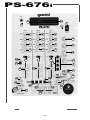
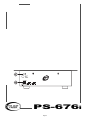
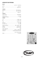
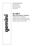
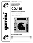
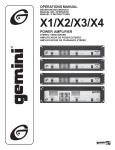
OPERATIONS MANUAL PS-676i PROFESSIONAL MIXER Page 1 PS-676i 26 27 3 1 2 6 6 6 7 7 7 8 8 8 9 9 9 16 17 18 28 10 12 21 11 19 14 13 20 5 15 4 22 36 42 34 35 33 43 44 24 23 37 25 Page 2 38 39 PS-676i Page 3 additional amplifier. INTRODUCTION Congratulations on purchasing a Gemini Platinum Series model PS-676i mixer. This state of the art mixer is backed by a three year warranty, excluding crossfader and channel slides. Prior to use. We suggest that you carefully read all the instructions. FEATURES • 5. On the rear panel are 2 stereo PHONO (32,34) inputs, 2 stereo LINE (31,33) inputs and 1 stereo PHONO/LINE (36) input. The PHONO/ LINE (35) switch enables you to set the (36) input to Phono or Line. The phono inputs will accept only turntables with a magnetic cartridge. A GROUND (37) screw to ground your turntables is located on the rear panel. The stereo line inputs will accept any line level input such as a CD player, a cassette player, etc. 6. Headphones can be plugged into the front panel mounted HEADPHONE (4) jack. Cut Feature for Low, Mid and High of each channel • Digital sampler THE GROUND LIFT SWITCH • 3 Stereo channels (3 Phono, 3 Line and 1 Mic) • 1/4" DJ Mic jack • Low, Mid ,High and Gain controls on each channel • Beat indicators • Master, Booth and Record outputs • Dual mode display (Left & Right output or Channel 2 and Channel 3) • Push button cueing with Cue/Program pan control D epending on your system configuration, applying the ground sometimes creates a quieter signal path. Sometimes “lifting” the ground eliminates loops and hum to create a quieter signal path. 1. Listen to the system with the unit ON, without music, and with the ground “applied”. GROUND LIFT SWITCH (41) should be to the left. 2. Turn power OFF before moving the GROUND LIFT SWITCH. 3. Now, “lift” the ground by moving the GROUND LIFT SWITCH to the right. Turn the power back ON and listen to determine which position provides a signal free of background noise and hum. CAUTIONS Note: Keep GROUND LIFT in the ground “applied” or left position if noise level remains the same in either position. 1. All operating instructions should be read before using this equipment. 2. To reduce the risk of electricai shock, do not open the unit. There are NO USER REPLACEABLE PARTS INSIDE. Please refer servicing to a qualified Gemini Sound Products service technician. h CAUTION:DO NOT TERMINATE THE AC GROUND ON THE POWER CABLE. TERMINATION OF THE AC GROUND CAN BE HAZARDOUS. OPERATION In the USA: if you experience problems with this unit, please call 1 (732) 969-9000 for Gemini Customer Service. 1. POWER ON: Once you have made all the equipment connections to your mixer, press the POWER SWITCH (1). The power will turn on and the POWER LED (2) will glow RED. Do not attempt to return this equipment to your dealer. 3. Do not expose this unit to direct sunlight or to a heat source such as a radiator or stove. 4. This unit should be cleaned only with a damp cloth. Avoid solvents or other cleaning detergents. 5. When moving this equipment, it should be placed in its original carton and packaging. This will reduce the risk of damage during transit. 6. DO NOT EXPOSE THIS UNIT TO RAIN OR MOISTURE. 7. DO NOT USE ANY SPRAY CLEANER OR LUBRICANT ON ANY CONTROLS OR SWITCHES. 2. CHANNEL 1: The GAIN (6), HIGH (7), MID (8), and LOW (9).Controls allows you to fully adjust the selected source. Switch (10) allows you to select either the mic or the PHONO/LINE (36) input. The CHANNEL (13) slide controls the output level of this channel. 3. MAIN CHANNEL SECTION:To assign an input source to a channel, first set the PHONO/LINE (11,12) switches to their appropriate positions. To make the proper adjustments to your music, set the GAIN (6), HIGH (7), MID (8) and LOW (9) controls and position the CHANNEL (14,15) slide. PLEASE NOTE:There is Low, Mid and High equalization for each channel with an extremely wide range of adjustment. CONNECTIONS SUGGESTION:You can use the Cut Features on each channel to remove Low, Mid and/or High range to create special effects. 1. Before plugging in the power cord, make sure that the VOLTAGE SELECTOR (30) switch is set to the correct voltage. F NOTE: This product is double insulated and is not intended to be grounded. 2. Make sure that the POWER (1) switch is in the off position. The POWER LED (2) will be off. T he Crossfader in your unit is removable and ,should the need arise, can easily be replaced by following these instructions. Note:Gemini replacement Crossfaders are available in three varieties: the RG-45 PRO (RAIL GLIDETM)Dual-Rail Crossfader; the RF45, which has a 45mm travel from side-to-side;and the PSF-45,which features a special “curve” designed for scratch mixing. 3. The PS-676i is supplied with four (4) sets of output jacks. 1. Unscrew the outside FADER PLATE SCREWS (B). • The 1/4" BALANCED OUT PUT (29) jacks are used to connect to your main amplifier using standard balanced cables. We recommend using balanced amp outputs if the cables to your amp are 25 feet or more. 123456 123456 123456 123456 123456 123456 - Do not touch INSIDE SCREWS (C). 2. Carefully remove old Crossfader and unplug CABLE (D). • The MAIN OUTPUT (38) (RCA type) jacks are unbalanced and used to connect to your main amplifier. 3. Plug new Crossfader into CABLE (D) and place back into mixer. • The REC OUTPUT (40) (RCA type) jacks can be used to connect the mixer to the record input of your recorder enabling you to record your mix. 4. Screw Crossfader to mixer with FADER PLATE SCREWS (B). • The BOOTH OUTPUT (39) (RCA type) jacks allow you to hook up an Page 4 123 123 123123 123 12 12 12 12 12345678901234567890 12345678901234567890 12345678901234567890 D Sampler Operation ✦ Your Gemini mixer comes with an RG-45 PRO (RAIL GLIDE) DUAL-RAIL CROSSFADER. Rail Glide™ Crossfaders have internal dual stainless steel rails that allow the slider to ride smoothly and accurately from end to end. The PS-676i Sampler uses Dynamic RAM Memory and a 12 bit microprocessor controller. The full bandwidth results in true sound reproduction. 4. CROSSFADER SECTION: The CROSSFADER (25) allows the mixing of one source into another. The left side of the CROSSFADER (25) is channel 2 and the right side is channel 3. 5. BEAT INDICATORS:Each side of the CROSSFADER (25) has its own BEAT INDICATOR (23,24). They flash at the low frequency peak level allowing you to match the beats visually. BEAT INDICATOR (23) will reflect the beat of the CH2 and BEAT INDICATOR (24) will do the same for CH3. 6. OUTPUT CONTROL SECTION:The level of the AMP OUT (38) is controlled by the MASTER (18) control. The BALANCE (17) control will allow the Amp Out signal to be balanced between the left and right speakers. The BOOTH (16) control adjusts the level of the BOOTH OUTPUT (39). 1. Put the MODE SELECTOR (36) switch into the WRITE position. 2. Select the source you want to sample from by pressing the appropriate ASSIGN BUTTON(44). 3. The PS-676i is equipped with a SAMPLER REC/PLAY LEVEL(43) control.When the MODE SELECTOR(36) is in the WRITE mode, this control acts as a record level control. If the OVERLOAD INDICATOR(42) is blinking, it means that the input signal you are going to sample is too strong and will cause the sample to be distorted. Lower the sample signal intensity by tuming the SAMPLER REC/PLAY LEVEL(43) control counterclockwise. 4. If the OVERLOAD INDICATOR(30) is off, turn the SAMPLER REC/ PLAY LEVEL(43) control clockwise until the OVERLOAD INDICATOR(42) begins to blink and then turn the SAMPLER REC/PLAY LEVEL(43) counter clockwise until the OVERLOAD INDICATOR(42) just goes off. HINT:BOOTH OUTPUT (39) is used by some DJs to run monitor speakers in the DJ Booth. You can also use it as a second ZONE or AMP output. F NOTE:The RECORD OUT (40) has no level control. The level is set by the channel slides and the gain controls of the selected channel. Tonal qualities are set by the low, mid and high controls of that same channel. 7. TALKOVER SECTION:The purpose of the talkover section is to allow the program playing to be muted so that the mic can be heard above the music. When the TALKOVER (19) button is pushed, the TALKOVER INDICATOR (28) will glow and the volume of all sources except the Mic or whatever is connected to the PHONO/LINE (36) input are reduced by -16 dB. 8. CUE SECTION:By connecting a set of headphones to the HEADPHONE (4) jack, you can monitor any or all of the channels. Select the correct CUE (21) button or buttons and their respective CUE LED (5) indicators will glow. Use the CUE LEVEL (20) control to adjust the headphone volume without effecting the overal mix. By sliding the CUE PGM PAN (22) control to the left you will be able to monitor the assigned cue signal. Sliding to the right will monitor the PGM (program) output. 5. Tapping the START/STOP(39) button begins the sampling process (the SAMPLER INDICATOR(38) will illuminate RED). Tapping the START/STOP(39) button a second time ends the sample (the SAMPLER INDICATOR(38) will tum off). If you do not tap the START/ STOP(39) button a second time, the sampling process will stop automatically after 12 seconds. SAMPLE PLAYBACK: 1. Put the MODE SELECTOR(36) switch into the SINGLE or REPEAT position. 2. When the MODE SELECTOR(36) is in the SINGLE or REPEAT mode, the SAMPLER REC/PLAY LEVEL(43) control acts as a Sampler Level Control. 3. Tapping the START/STOP(39) button with the MODE SELECTOR(36) in the SINGLE position will cause the sampler to playback one time (the SAMPLER INDICATOR(38) will illuminate GREEN). Every push of the START/STOP(39) button will restart the sample from the beginning. Rapid pressing of the START/STOP(39) button will cause a stuttering effect. Once the sample has started playback and the START/STOP(39) button is not pushed a second time, the sample will play to the end and then stop (the SAMPLER INDICATOR(38) will illuminate turn off). 9. DISPLAY:The peak hold, dual function DISPLAY (26) indicates either the MASTER (38) output left and right levels or the channel 2 and channel 3 levels. You can choose the option you want by pressing the DISPLAY (27) button. F NOTE:When the DISPLAY (27) is in the channel 2/channel 3 display mode, by adjusting the individual channel gain and tone controls, you can increase or decrease the signal to match the other channel’s signal. The channel slides and crossfader have no effect on the display readings. 10. The CROSSFADER CURVE SWITCH (31) allows you to adjust the kind of curve the crossfader has Move switch to the “sharp” position to make the curve steep and cutting (perfect for scratching ). Move switch to the “gradual” position to make the curve gradual and gentle. The CROSSFADER REVERSE SWITCH (32) allows you to reverse the crossfader so that CHANNEL 3 is controlled by the left side of the crossfader and CHANNEL 2 is controlled by the right side of the crossfader. NOTE: When the CROSSFADER REVERSE SWITCH (32) is activated, only the crossfader reverses. The Channel Slides, Gain, and tonal controls do not reverse. SAMPLE RECORD: 4. Tapping the START/STOP(39) button with the MODE SELECTOR(36) in the REPEAT position will cause the sample to continuously play over and over (the SAMPLER INDICATOR(38) will illuminate GREEN). The START/STOP(39) button will act as an on/off switch. The first push will start the sample, the second push will stop it. ROBO PLAY: 1. With the ROBO PLAY(33) button in the OFF position (the ROBO PLAY INDICATOR(34) will be OFF ) and the MODE SELECTOR(36) switch in either the SINGLE or REPEAT mode, pressing the START/STOP(39) will cause the sample to play along with the signal going through the mixer. 2. When the ROBO PLAY(33) button is in the ON position (the ROBO PLAY INDICATOR(34) illuminates RED), starting the sampler mutes the signal going through the mixer. When the sample ends, the signal automatically turns back on. PITCH CONTROL: The PS-676i comes equipped with a sampler PITCH(35) control. To get a perfect sample, set the control to its center position and record the sample. Page 5 SPECIFICATIONS INPUTS: DJ Mic.......................................................1.5mV 2 kΩ unbalanced Phono.............................................................................3mV 47 kΩ Line...............................................................................150 mV 27 kΩ OUTPUTS: Amp/Booth....................................................................0 dB 775mV 400 Ω Max...............................................................................24V Peak-to-Peak Rec..................................................................................225mV 5 kΩ SAMPLER: Sampler System.................................................................12 Bit Sampling Sample Length ............................................................12 Seconds Total Memory Capacity ................................................................1 Mbit GENERAL: Low .....................................................................+ 12dB/- 32 dB Mid ..........................................................................+ 12dB/- 32 dB High..................................................................+ 12dB/- 32 dB Gain (Mic).......................................................................0 to -40dB Gain (Chnls 1-3).......................................................................0 to -20dB Frequency Response............................................20Hz - 20kHz +/- 2dB Distortion............................................................................less than 0.02% S/N Ratio..........................................................................better than 80dB Talkover Attenuation........................................................................16dB Power Source...................................................115/230V 50/60Hz 15W Dimensions................................................254mmW x 305mmD x 112mmH 10”W x 12”D x 4 7/16”H Weight........................................................................................6.5 lbs(3 Kg) Page 6 In the USA: If you experience problems with this unit, call 1 (732) 969-9000 for Gemini Customer Service. Do not attempt to return this equipment to your dealer. Parts of the design of this product may be protected by worldwide patents. Information in this manual is subject to change without notice and does not represent a commitment on the part of the vendor. Gemini Sound Products Corp. shall not be liable for any loss or damage whatsoever arising from the use of information or any error contained in this manual. No part of this manual may be reproduced, stored in a retrieval system or transmitted, in any form or by any means, electronic, electrical, mechanical, optical, chemical, including photocopying and recording, for any purpose without the express written permission of Gemini Sound Products Corp. It is recommended that all maintenance and service on this product is performed by Gemini Sound Products Corp. or its authorized agents. Gemini Sound Products Corp. will not accept liability for loss or damage caused by maintenance or repair performed by unauthorized personnel. Worldwide Headquarters • 8 Germak Drive, Carteret, NJ 07008 • USA Tel: (732) 969-9000 • Fax: (732) 969-9090 France • G.S.L. France • 11, Avenue Leon Harmel, Z.I. Antony, 92160 Antony, France Tel: + 33 (0) 1 55 59 04 70 • Fax: + 33 (0) 1 55 59 04 80 Germany • Gemini Sound Products GmbH • Ottostrasse 6, 85757 Karlsfeld, Germany Tel: 08131 - 39171-0 • Fax: 08131 - 39171-9 UK • Gemini Sound Products • Unit C4 Hazleton Industrial Estate, Waterlooville, UK P08 9JU Tel: 087 087 00880 • Fax: 087 087 00990 Spain • Gemini Sound Products S.A. • Mino, 112, Nave 1, 08223 Terrassa, Barcelona, Spain Tel: 011-34-93-736-34-00 • Fax: 011-34-93-736-34-01 © Gemini Sound Products Corp. 2001 Page 7 All Rights Reserved