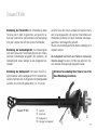
1
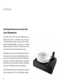
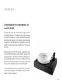
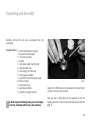
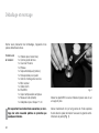
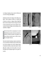
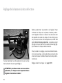
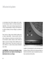
TD 160 HD
Bedienungsanleitung
User Manual
Mode d’Emploi
www.thorens.com
TD 160 HD
Bedienungsanleitung
User Manual
Mode d’Emploi
Inhalt
EINLEITUNG
6
SICHERHEITSHINWEISE
7
AUSPACKEN UND MONTAGE 8
AUFSTELLUNG UND ANSCHLUSS
11
INSTALLATION DES TONABNEHMERS
13
EINSTELLUNG DER TONARMHÖHE
14
FEINJUSTAGE DES TONABNEHMERS
15
TONARM TP 250
16
TONARM TP 300
17
BETRIEB DES PLATTENSPIELERS
18
WARTUNG UND PFLEGE
19
TECHNISCHE DATEN
SERVICEINFORMATIONEN
20
21
Table of Contents
INTRODUCTION
Table des matiéres
23
INTRODUCTION
HINTS FOR SAFETY AND PRECAUTION
24
CONSIGNES DE SECURITE
UNPACKING AND ASSEMBLY 25
DEBALLAGE ET MONTAGE
42
SET UP AND CONNECTIONS
28
INSTALLATION ET RACCORDEMENT
45
MOUNTING THE PICKUP CARTRIDGE
30
INSTALLATION DE LA CELLULE DE LECTURE
47
ADJUSTING TONEARM HEIGHT
31
REGLAGE DE LA HAUTEUR DU BRAS 48
ALIGNMENT OF PICKUP CARTRIDGE
32
REGLAGE PRECIS DE LA CELLULE
49
TONEARM TP 250
33
BRAS DE LECTURE TP 250
50
TONEARM TP 300
34
BRAS DE LECTURE TP 300
51
OPERATION
35
UTILISATION DE LA PLATINE
52
36
MAINTENANCE ET ENTRETIEN 53
TECHNICAL SPECIFICATIONS
37
DONNEES TECHNIQUES
54
SERVICE INFORMATION
38
INFORMATIONS SERVICE APRES-VENTE
MAINTENANCE AND CARE
40
41
55
Einleitung
Herzlichen Glückwunsch zum Kauf Ihres
neuen Plattenspielers.
Wir hoffen, dass Sie mit Ihrem neuen Plattenspieler viel
Freude haben werden. In Verbindung mit einem guten
Tonabnehmersystem besitzt dieses Laufwerk herausragende Wiedergabequalitäten. Fertigung und Montage
erfolgen komplett in Deutschland, so dass Sie sich auch
noch nach Jahren auf das Gerät verlassen können.
Bitte denken Sie daran, dass dieser Plattenspieler ein Präzisionsinstrument ist, das stets mit Sorgfalt behandelt werden muss. Wir empfehlen Ihnen daher, diese Bedienungsanleitung vor der ersten Ingebrauchnahme aufmerksam
durchzulesen. Sie enthält wichtige Hinweise für Aufstellung,
Anschluss und Konfiguration Ihres neuen Laufwerks.
Sollten Sie darüber hinaus noch Fragen haben, so können
Sie sich jederzeit an Ihren Thorens Fachhändler wenden.
6
Sicherheitshinweise
BITTE VOR DER ERSTMALIGEN INBETRIEBNAHME
AUFMERKSAM LESEN!
Dieses Elektronikprodukt entspricht den gültigen Richtlinien
zur Erlangung des CE-Zeichens. Alle notwendigen Prüfungen
wurden mit positivem Ergebnis vorgenommen.
VORSICHT
Um einen elektrischen Schlag zu vermeiden, darf das Gehäuse des
Netzteils nicht geöffnet werden. Im Geräteinneren befinden sich keine
vom Benutzer zu wartenden Teile.
WARNUNG
UM DER GEFAHR VON FEUER UND EINES ELEKTRISCHEN SCHLAGES VORZUBEUGEN, DARF DAS GERÄT WEDER REGEN NOCH
FEUCHTIGKEIT AUSGESETZT WERDEN.
ERLÄUTERUNG DER GRAFISCHEN SYMBOLE
Das Blitz-Symbol mit dem nach unten weisenden
Pfeil im gleichseitigen Dreieck warnt vor “gefährlicher Spannung” im Gehäuseinneren, deren Höhe für
eine Gefährdung von Personen durch einen Stromschlag ausreichend ist.
Das Ausrufezeichen innerhalb des gleichseitigen
Dreiecks macht auf wichtige Bedienungs- und Wartungshinweise in der beiliegenden Bedienungsanleitung aufmerksam.
2002/95/EC (RoHS) konform.
WICHTIG: ENTSORGUNG VON ELEKTROGERÄTEN DURCH VERBRAUCHER IN PRIVATEN
HAUSHALTEN INNERHALB DER EU
Dieses Symbol auf dem Produkt oder dessen Verpackung gibt an, dass dieses Produkt nicht zusammen
mit dem Restmüll entsorgt werden darf. Es obliegt
daher Ihrer Verantwortung, das Gerät an einer entsprechenden Stelle für die Entsorgung oder Wiederverwertung von Elektrogeräten aller Art abzugeben
(z.B. ein Werkstoffhof). Die separate Sammlung und
das Recyceln Ihrer alten Elektrogeräte zum Zeitpunkt
ihrer Entsorgung trägt zum Schutz der Umwelt bei
und gewährleistet, dass sie auf eine Art und Weise
recycelt werden, die keine Gefährdung für die Gesundheit von Mensch und Umwelt darstellt. Weitere Informationen darüber, wo Sie alte Elektrogeräte zum Recyceln abgeben können, erhalten Sie bei
den örtlichen Behörden, Werkstoffhöfen oder dort,
wo Sie das Gerät erworben haben.
7
Auspacken und Montage
Nehmen Sie das Gerät und die mitgelieferten Einzelteile
vorsichtig aus der Verpackung.
Lieferumfang:
1 x Chassis (mit/ohne Tonarm)
1 x Tonarmgewicht
1 x Thorens Antriebsriemen
1 x Plattenteller
1 x Antistatische Matte (2 Teile)
1 x Spezial Lageröl
1 x Montagehilfe für Antriebsriemen
1 x Steckernetzteil
1 x Cinchkabel
3 x RDC-Gerätefuß
1 x Staubschutzhaube aus Acryl
1 x Wasserwaage (Libelle)
1 x Adapter für 17cm-Schallplatten
Bei Beachtung der nachfolgenden Hinweise wird
die Montage Ihres neuen Plattenspielers nur wenige Minuten in Anspruch nehmen.
8
Abbildung 1
Schrauben Sie die RDC-Füße an der Unterseite des Chassis an und stellen Sie dieses auf eine ebene Unterlage.
Geben Sie nun fünf bis acht Tropfen des mitgelieferten
Spezialöls in das Lager und setzen Sie die Achse mit dem
dickeren Ende voran in das Lager ein (Abb. 1).
Die Montage von Plattenteller und Antriebsriemen erfolgt
durch eine spezielle Montagehilfe (Abb. 2.1).
Bringen Sie die Metallbügel der Montagehilfe wie in Abb.
2.1 dargestellt in Position. Legen Sie den Plattenteller umgedreht auf eine ebene Unterlage und spannen Sie den
Riemen um den integrierten Subteller (Abb. 2.2). Haken Sie
nun die Monatgehilfe im Riemen ein und ziehen Sie diesen
vorsichtig bis zum Rand des Tellers. Befestigen Sie Riemen
und Monagehilfe wie in Abb. 2.3 dargestellt am Tellerrand.
Abbildung 2.1
Abbildung 2.2
Abbildung 2.3
Abbildung 2.4
Vermeiden Sie Öl- oder Fettspuren auf Antriebsriemen,
Motor-Riemenscheibe und der Lauffläche im Inneren
des Plattentellers. Falls notwendig, können Sie diese
Teile mit einem in reinem Alkohol getränkten, nicht fasernden Tuch oder Lappen reinigen.
Drehen Sie nun den Teller um und setzen Sie ihn vorsichtig auf die Achse. Platzieren Sie ihn dabei so, dass die
durch die Montagehilfe gebildete Fläche zwischen Riemen
und Subteller genau über der Motor-Riemenscheibe liegt
(Abb. 2.4). Der Teller sitzt richtig, wenn er sich nur noch
wenige Grad nach links und rechts bewegen lässt.
9
Drehen Sie nun die Drahtbügel der Montagehilfe nacheinander nach innen (Abb. 3.1), hierdurch wird der Riemen
freigegeben und legt sich um die Riemenscheibe. Entfernen Sie die Montagehilfe wie in Abb. 3.2 dargestellt. Drehen Sie den Teller anschließend einige Male von Hand um
den korrekten Sitz des Riemens zu überprüfen.
Legen Sie die spezielle Kautschuk-Polymer-Matte auf den
Plattenteller (Abb. 3.3). Die zwei Teile der Matte ermöglichen es, unterschiedlich dicke Schallplatten abzuspielen,
ohne die Höhe des Tonarms (VTA, siehe Seite 14) verändern zu müssen.
Abbildung 3.1
Wurde Ihr Plattenspieler ohne Tonarm geliefert, so montieren Sie diesen nun bitte nach der Anleitung des Herstellers.
Ansonsten ist der Plattenspieler nun vollständig montiert
und kann aufgestellt und angeschlossen werden.
WICHTIG: Bitte bewahren Sie die Verpackung auf, falls das
Gerät einmal zum Transport verpackt werden muss. Für
Transportschäden durch unsachgemäße Verpackung wird
keine Haftung übernommen!
10
Abbildung 3.3
Abbildung 3.2
Aufstellung und Anschluss
Stellen Sie den Plattenspieler auf eine stabile Unterlage
und richten Sie ihn so aus, dass er waagrecht steht. Sie
können die Höhe der Füße anpassen, indem Sie diese
drehen. Kontrollieren Sie die Höheneinstellung danach
mithilfe einer Wasserwaage und korrigieren Sie diese gegebenenfalls.
Verbinden Sie nun mit Hilfe des Cinchkabels die Ausgangsbuchsen des Plattenspielers mit dem (Phono-) Eingang Ihres Verstärkers. Achten Sie hierbei unbedingt auf
eine korrekte Polung (linker-/rechter Kanal!).
Hinweis: Für Verstärker ohne Phonoeingang wird zusätzlich ein spezieller Phonovorverstärker benötigt. Für Verstärker mit einer 5-poligen Eingangsbuchse nach DIN wird
zusätzlich ein spezielles Adapterkabel benötigt. Bitte wenden Sie sich in diesen Fällen an Ihren Fachhändler.
11
Achten Sie bei der Aufstellung Ihres neuen Plattenspielers
darauf, einen Mindestabstand zu anderen elektronischen
Geräten (z.B. Verstärker, Receiver oder CD-Spieler) einzuhalten, da es sonst zu magnetischen Einstrahlungen auf
das Tonabnehmersystem kommen kann, welche sich
durch Brummstörungen in der Wiedergabe äußern.
Thorens Plattenspieler sind relativ unempfindlich gegenüber Erschütterungen. Dennoch stellen diese ein generelles
Problem bei der Plattenwiedergabe mit hochwertigen Tonabnehmern dar. Wählen Sie deshalb ein möglichst stabiles
Möbelstück zur Aufstellung und vermeiden Sie die Nähe
zu Lautsprechern.
Magnetische Störungen kann man leicht ermitteln und
beseitigen, indem man Aufstellung und Position der
Geräte zueinander verändert.
Leider reicht dies in älteren Häusern mit Holzbalkendecken bisweilen nicht aus. In der Regel hilft hier allerdings
die Aufstellung des Plattenspielers auf einer Konsole, die
mit geeigneten Konsolenträgern an einer tragenden Zimmerwand befestigt wird.
12
Installation des Tonabnehmers
Installieren und konfigurieren Sie Ihr Tonabnehmersystem
entsprechend der Montageanleitung des Herstellers und
nehmen Sie alle notwendigen Einstellungen vor.
An den Thorens Tonarmen können Tonabnehmersysteme
mit einem standardisierten Abstand der Befestigungslöcher von 12,5 mm (1/2 ”) montiert werden.
Im Folgenden erhalten Sie einige Hinweise zur Installation und Konfiguration von Thorens Tonarmen, die analog
auch für andere Fabrikate gelten können. Halten Sie sich
jedoch im Zweifel immer an die Anleitung des jeweiligen
Herstellers. Spezielle Konfigurationshinweise für den Thorens Tonarm TP 250 / TP 300 finden Sie ab Seite 16.
Die vier farblich gekennzeichneten Anschlusslitzen werden
auf die entsprechenden Anschluss-Stifte (identische Farbe) des Tonabnehmersystems geschoben.
Hinweis: Sollte Ihr Plattenspieler mit montiertem Tonarm
und Tonabnehmersystem geliefert worden sein, so sind
alle Einstellungen bereits werkseitig vorgenommen. Einzig die Auflagekraft muss noch eingestellt werden, da das
Tonarmgewicht für den Transport deinstalliert wurde.
Montieren Sie den Tonabnehmer in die dafür vorgesehenen Bohrungen des Tonabnehmerkopfs. Belassen Sie
dabei den Nadelschutz – wenn möglich – auf dem Tonabnehmer, um Beschädigungen der Abtastnadel zu vermeiden.
R
G
L
G
rechter Kanal, rot (Signal)
rechter Kanal, grün (Masse)
linker Kanal, weiß (Signal)
linker Kanal, blau (Masse)
Ziehen Sie die Montageschuhe zunächst nur lose ab. Die
Feinjustage des Tonabnehmers erfolgt nach dem Einstellen der Tonarmhöhe.
Hinweis: Bei Grado Tonabnehmern sollten die mitgelieferten Schrauben von unten durch den Tonabnehmer
geführt werden und die Mutter oben auf das Headshell
geschraubt werden, da sie am Systemkörper nur schwer
zu verwenden sind.
13
Einstellung der Tonarmhöhe
Entfernen Sie vorsichtig den Nadelschutz. Legen Sie nun
eine Schallplatte auf und senken Sie die Abtastnadel vorsichtig ab. Das Tonarmrohr sollte parallel zur Plattenoberfläche stehen. Ist dies nicht der Fall, so muss die Tonarmhöhe mittels VTA justiert werden. VTA bedeutet Vertical
Tracking Adjustment, dieses System ermöglicht es, den
Tonarm mithilfe eines Klemmmechanismus (Abb. 4) auf
die Höhe des jeweiligen Tonabnehmers einzustellen.
Abbildung 4
Drehen Sie das Tonarmgewicht in Richtung der Tonarmbank auf den Tonarm (Abb. 4).
ACHTUNG: Gehen Sie im Folgenden extrem vorsichtig vor, da jeder Fehler die Abtastnadel des
Tonabnehmers zerstören kann!
14
Um die Einstellung vorzunehmen, müssen Sie zunächst
die Klemmschraube öffnen. Anschließend kann der Tonarm in die gewünschte Höhe gebracht werden. Ziehen Sie
die Schraube nun vorsichtig wieder an.
Einstellung der Auflagekraft: siehe Seite 16/17.
Feinjustage des Tonabnehmers
Nur bei einer genauen Justage des Tonabnehmersystems
kommen die hervorragenden Klangeigenschaften dieses
Laufwerks voll zur Geltung. Sollten Sie hierbei Probleme
haben, so hilft Ihnen Ihr Fachhändler gerne weiter.
ACHTUNG: Bei der Feinjustage des Tonabnehmers ist größte Sorgfalt geboten, damit weder
Abtastnadel noch die empfindliche Feinmechanik des Tonarms beschädigt werden. Sollten Sie
hierin keinerlei Erfahrung haben, so empfehlen
wir Ihnen, dies einem Fachmann zu überlassen.
Falsch eingestellte Tonabnehmersysteme können zu starkem Klangverlust bis hin zu Schäden
an der Schallplatte führen!
Kröpfungswinkel: Der Kröpfungswinkel ist der Winkel
zwischen der Längsachse des Tonabnehmers und der
Tonarmachse. Bei allen Drehpunktarmen (wie der Tonarm
TP 250 / TP 300) liegen die optimalen Werte zwischen
21° und 24°. Zur Einstellung benötigen Sie eine spezielle
Schablone, welche im Fachhandel erhältlich ist.
Überhang: Der Überhang ist die Strecke, welche die Tonabnehmernadel über die Plattentellermitte hinausragt. Der
Überhang sollte beim Tonarm TP 250 / TP 300 ca. 17
mm betragen. Zur Einstellung benötigen Sie eine spezielle
Schablone, welche im Fachhandel erhältlich ist.
Azimut: Dies ist der Winkel zwischen Nadelträger und
Schallplattenrille. Er sollte 90° betragen (hiervon ausgenommen sind Systeme, deren Nadel absichtlich schief
eingebaut ist). Der Azimut kann am TP 250 / TP 300 nicht
eingestellt werden. Sie sollten mit diesem Tonarm daher
nur Tonabnehmer verwenden, die einen korrekten Azimut
besitzen.
15
Tonarm TP 250
Einstellung des Tonarmlifts: Die Lifteinstellung dieses
Tonarms wird im Werk vorgenommen und passt für nahezu alle Tonabnehmer. Sollte trotzdem eine Nachjustage
nötig sein, wenden Sie sich bitte an Ihren Fachhändler.
Einstellung der Antiskatingkraft: Die Antiskatingkraft
wird durch den auf der Tonarmbank (2) unter dem Tonarm
sitzenden Schieberegler eingestellt. Wir empfehlen, die
Antiskatingkraft etwas niedriger als die Auflagekraft einzustellen.
Einstellung der Auflagekraft: Informieren Sie sich zunächst darüber, welche Auflagekraft für Ihr Tonabnehmersystem empfohlen wird. Im Allgemeinen sind Auflagekräfte
zwischen 10 und 25 mN gebräuchlich (1,0 - 2,5 pond).
Zunächst muss der Tonarm ausbalanciert werden. Hierzu
wird er bei abgesenktem Lift zwischen Tonarmstütze und
Tonarm TP 250
16
➀
➁
➂
Plattenteller positioniert und durch Verdrehen des Gegengewichtes in die Waagrechte gebracht.
Hinweis: Die Antiskatingkraft sollte hierbei unbedingt auf 0
reduziert werden!
Sie können die Auflagekraft nun durch Drehen des Gegengewichts (3) nach folgendem Schema einstellen:
Eine halbe Umdrehung des Gewichts entspricht einer
Auflagekraft von 10 mN, eine volle entspricht 20 mN.
Drehen in Richtung der Tonarmbank erhöht die Auflagekraft, Drehen in entgegengesetzter Richtung verringert sie.
Die grünen Punkte am Gewicht dienen zur Orientierung.
Arretieren Sie unbedingt den Tonarm, bevor Sie
diese Einstellung vornehmen.
➁
Tonarmlift
Tonarmbank
Gegengewicht
➂
➀
Tonarm TP 300
Einstellung des Tonarmlifts: Die Lifteinstellung dieses
Tonarms wird im Werk vorgenommen und passt für nahezu alle Tonabnehmer. Sollte trotzdem eine Nachjustage
nötig sein, wenden Sie sich bitte an Ihren Fachhändler.
Einstellung der Antiskatingkraft: Die Antiskatingkraft
wird durch den auf der Tonarmbank (2) unter dem Tonarm
sitzenden Schieberegler eingestellt. Wir empfehlen, die
Antiskatingkraft etwas niedriger als die Auflagekraft einzustellen.
Zunächst muss der Tonarm ausbalanciert werden. Hierzu
wird er bei abgesenktem Lift zwischen Tonarmstütze und
Plattenteller positioniert und durch Verdrehen des Gegengewichtes in die Waagrechte gebracht.
Hinweis: Die Antiskatingkraft sollte hierbei unbedingt auf 0
reduziert werden!
Die Auflagekraft wird durch eine Feder im Inneren des
Tonarms erzeugt. Sie kann mit Hilfe des seitlich am Tonarm sitzenden Drehreglers (4) eingestellt werden.
Einstellung der Auflagekraft: Informieren Sie sich zunächst darüber, welche Auflagekraft für Ihr Tonabnehmersystem empfohlen wird. Im Allgemeinen sind Auflagekräfte
zwischen 10 und 25 mN gebräuchlich (1,0 - 2,5 pond).
Tonarm TP 300
➀
➁
➂
➃
Arretieren Sie unbedingt den Tonarm, bevor Sie
diese Einstellung vornehmen.
Tonarmlift
Tonarmbank
Gegengewicht
Drehregler für Auflagekraft
➁
➀
➃
➂
17
Betrieb des Plattenspielers
Der neben dem Plattenteller angeordnete Schalter dient
zur Geschwindigkeitsauswahl. Folgende Geschwindigkeiten stehen zur Verfügung: 33 ⅓ U/min für Langspielplatten und 45 U/min für kleine Schallplatten. Befindet sich
der Schalter in der Mittelposition (wie in Abb. 6 zu sehen),
ist der Plattenspieler ausgeschaltet.
Zum Abspielen einer Platte wird der Plattenspieler zunächst mit der entsprechenden Geschwindigkeit gestartet. Dann wird der Tonarmlift angehoben. Hierzu muss
der Hebel nach hinten oben bewegt werden. Nun wird
der Tonabnehmer über der Einlaufrille oder über dem gewünschten Stück positioniert und anschließend mit Hilfe
des Lifts auf die Platte abgesenkt. Bewegen Sie den Lift
hierzu leicht nach vorne unten und lassen Sie ihn los. Der
Tonarm senkt sich nun langsam von alleine ab.
ACHTUNG: Beschleunigen Sie den Absenkvorgang des Tonarmlifts keinesfalls, indem Sie von
Hand nachhelfen, da hierdurch Tonabnehmer
oder Schallplatte beschädigt werden können.
18
Abbildung 6
Der Plattenspieler besitzt keine automatische Endabschaltung. Sobald die Auslaufrille erreicht ist, muss der Tonarm
mittels Handlift von der Platte gehoben und der Plattenspieler abgeschaltet werden.
Wartung und Pflege
Ihr Plattenspieler benötigt keinerlei ständige Wartung.
Von Zeit zu Zeit können Sie fünf bis acht Tropfen des
mitgelieferten Spezialöls in das Lager geben, um seine
Schmierung zu verbessern (siehe auch Seite 8).
Staub, der sich im Laufe der Zeit auf dem Chassis absetzt,
kann mit einem weichen und feuchten Tuch entfernt werden. Hinweis: Verwenden Sie zur Reinigung am besten ein
feuchtes Brillenputztuch.
Ein trockenes Tuch kann unerwünschte elektrostatische Aufladungen verursachen.
Den Thorens Präzisionsriemen sollten Sie alle 2 Jahre ersetzen. Sollte das Gerät über längere Zeit nicht in Betrieb
sein, so empfiehlt es sich, den Riemen zu demontieren,
um einer vorzeitigen Alterung vorzubeugen.
19
Technische Daten
Modell
TD 160 HD
Funktion
Antriebssystem
Motor
Geschwindigkeiten
Umschaltung
Plattenteller
Tonarm
Anti-Skating
Endabschaltung
Kabelkapazität
Stromversorgung
manuell
Riemenantrieb (innenliegend)
elektronisch geregelter AC-Synchronmotor
33 ⅓, 45 U/min
elektronisch
12” Acrylteller mit 2,0 kg
Thorens TP 250 / TP 300 (standard)
Magnet (TP 250 / TP 300)
–
120 pF
externes Steckernetzteil
15 - 18 V AC, min. 300 mA
430 x 175 x 340 mm (B x H x T)
8,0 kg
Abmessungen
Gewicht
Technische Änderungen vorbehalten. Hergestellt in Deutschland.
20
Serviceinformationen
Ihr Fachhändler oder Vertrieb sind jederzeit kompetente
Ansprechpartner, die Ihnen bei sämtlichen Fragen rund
um Ihr Thorens Produkt gerne zur Verfügung stehen.
Sie können Thorens auch direkt kontaktieren:
Thorens Export Company AG
Im Huebel 1, CH-4304 Giebenach, Schweiz
www.thorens.com, [email protected]
Bitte kontaktieren Sie im Garantiefall immer zuerst Ihren
Fachhändler oder Vertrieb!
Weitere Informationen unter:
www.thorens.com/de
21
Notizen
22
Introduction
Congratulations for your purchase of the
new TD 160 HD!
We hope that your new record player will give you lots
of listening pleasure. In combination with a good pickup
cartridge this turntable is to yield outstanding sound. Manufacturing and assembly of this record player has been
carried out in Germany which will guarantee you its high
quality and functionality being maintained for many years
to come.
Please keep in mind that this device is a precision instrument and therefore requires some attention and care. We
strongly advise to read these instructions attentively before proceeding with the set-up as it contains all necessary information and guidance for assembly, placement,
set-up and configuration of your new record player.
In the event that you have any question this user manual
cannot answer please do not hesitate to ask your Thorens
dealer for further assistance.
23
Safety instructions
PLEASE READ THIS PAGE CAREFULLY BEFORE
OPERATING YOUR UNIT!
This product was tested and complies with all the
requirements for the CE Mark.
CAUTION
To reduce risk of electric shock, do not remove the cover (or back).
No user-serviceable parts inside.
WARNING
TO PREVENT FIRE OR SHOCK HAZARD, DO NOT EXPOSE THIS
APPLIANCE TO RAIN OR MOISTURE.
EXPLANATION OF GRAPHICAL SYMBOLS
The lightning flash with arrowhead symbol, within
an equilateral triangle, is intended to alert you to
the presence of uninsulated ‘dangerous voltage’
within the product’s enclosure that may be of sufficient magnitude to constitute an electric shock to
persons.
The exclamation point within an equilateral triangle
is intended to alert you to the presence of important
operating and maintenance (servicing) instructions in
the literature accompanying the appliance.
24
Compliant to 2002/95/EC (RoHS)
IMPORTANT: DISPOSAL OF WASTE EQUIPMENT BY USERS IN PRIVATE HOUSEHOLDS
IN THE EUROPEAN UNION
This symbol on the product or on its packaging indicates that this product must not be disposed off
with your other household waste. Instead, it is your
responsibility to dispose of your waste equipment by
handing it over to a designated collection point for
the recycling of waste electrical and electronic equipment. The separate collection and recycling of your
waste equipment at the time of disposal will help to
conserve natural resources and ensure that it is recycled in a manner that protects human health and
the environment. For more information about where
you can drop off your waste equipment for recycling,
please contact your local city office, your household
waste disposal service or the shop where you purchased the product.
Unpacking and Assembly
Carefully remove the unit and accessories from the
packaging.
Supplied items: 1 x plinth (with/without tonearm)
1 x tonearm counterweight
1 x Thorens drive belt
1 x platter
1 x anti-static platter mat (2 parts)
1 x special bearing oil
1 x mounting jig for drive belt
1 x mains power adaptor
1 x set of RCA interconnecting leads
3 x RDC unit feet
1 x acryl dust cover
1 x sprit level (bubble)
1 x adaptor for single records
By observing the following hints your record player can be mounted within only a few minutes.
Fig. 1
Attach the 3 RDC-feet at the underside of the plinth and
put the unit onto a level surface.
Now put five to eight drops of the supplied oil into the
bearing and then insert the axle with the thicker end first
(Fig. 1).
25
Mounting platter and belt is carried out with the dedicated
jig supplied (Fig. 2.1).
Put the metal stems oft the mounting jig into a position as
shown in Fig. 2.1. Put the platter upside down onto a level
surface and stretch the rubber belt around the integrated
sub-platter (Fig. 2.2). Hook the stems of the mounting jig
into belt and carefully pull to the inner rim of the platter. Fix
belt and jig at the rim as shown in Fig. 2.3.
Fig. 2.1
Fig. 2.2
Fig. 2.3
Fig. 2.4
Avoid any oil or greasy substance to get onto the belt
and the transmission area of sub-platter and motor pulley. If necessary you may clean them with a lint-free tissue lightly soaked in an alcoholic dilution (e.g. ethanol).
Now turn platter back again and put it carefully onto the
bearing axle. Position platter in a way that the area between belt and inner platter rim as formed by the mounting
jig is to come exactly over the motor pulley (Fig. 2.4). The
platter has been correctly positioned if it can be moved to
the left or right by only a few degrees.
26
The stems of the mounting jig are now to be turned inwards, one after the other (Fig. 3.1), whereupon the belt
will be freed and loop itself around the motor pulley. Remove the mounting jig as shown in Fig. 3.2. Turn the platter manually clock-wise several times in order to make sure
that the belt fits snugly around sub-platter and pulley.
Place the dedicated rubber-polymer mat onto platter (Fig.
3.3). The two pieces are to compensate vinyl records of
different thickness without having to alter tonearm height
(VTA; see page 31).
Fig. 3.1
Fig. 3.2
If your TD 160 HD has been delivered without tonearm
you may now proceed to mount and align the tonearm of
your choice according to the instructions supplied by its
manufacturer. Otherwise the mounting of your TD 160 HD
is complete and can now be set up and connected.
IMPORTANT: it is highly recommended to save the shipping box and all packing material in case your record player
needs to be packed again for transportation. Thorens cannot be held responsible for any damage that may occur
during transport owing to the record player not been properly packed
Fig. 3.3
27
Set up and Connections
Place the record player onto a stable foundation and after the final position has been achieved make sure that
the plinth is fairly level. For any fine-adjustments turn the
tip of each foot up or down until the plinth is in a perfect
horizontal position. This procedure is best controlled (and
to be corrected if necessary) with the help of the supplied
spirit level.
Take the RCA interconnect leads and plug them into the
designated (phono) input jacks at the rear panel of your
amplifier or receiver. Make sure that polarity (left/right
channel!) is correct.
HINT: if your amplifier lacks an integrated phono stage you
need to acquire a special external phono-preamplifier. For
amplifiers/receivers featuring a 5-pin DIN-socket at the
phono input section you will need a special adaptor (RCA
to DIN) which can be requested from your Thorens dealer.
28
While placing the record player onto its final position make
sure that it is a fair distance away from other audio devices
(such as amplifier, receiver or CD player). This measure
is to avoid electro-magnetic interferences which can yield
a distorting effect in the sensitive pickup cartridge which
may be audible as hum during playback.
Electro-magnetic interferences however can be disclosed and eliminated by simply changing the position
of the record player with respect to the other audio
components.
Thorens record players are relatively insensitive when subject to foot-fall shocks or airborne vibrations. Nevertheless, a general problem remains when it comes to playing
back vinyl records with a high-quality pickup cartridge. It
is therefore highly recommended to choose a sturdy piece
of furniture or a rack for placement whereby any close
proximity of the record player to the loudspeakers is to be
avoided.
Under certain circumstances all these precautions may not
be good enough in older houses with wooden floor construction. Here, in most cases a solid shelf firmly mounted
to a supporting wall can be very beneficial for the sonic
properties of the record player if it is placed on such a shelf
or console.
29
Mounting the Pickup Cartridge
You can now mount and adjust your pickup cartridge according to the instructions provided with the pickup. Proceed with making all necessary alignments.
In the following you‘ll find some comprehensive instructions concerning the correct mounting of Thorens tonearms, which may accordingly be used for mounting foreign tonearms as well. However, if in doubt you should in
any case resort to the original instructions provided by the
manufacturer of the tonearm. Special hints concerning the
configuration of the Thorens tonearms TP 250 / TP 300
are to be found on page 33/34 of this manual.
Thorens tonearms will accept any pickup cartridge with
standard fixing hole distance of 12.5 mm (1/2”).
Carefully and with the help of tweezers, the four colourcoded fine litz wires coming from the tonearm‘s headshell
are attached to the respective pins with identical colour at
the rear side of the cartridge.
R
G
L
G
right channel, red (signal)
right channel, green (ground)
left channel, white (signal)
left channel, blue (ground)
HINT: if you happen to have acquired this record player as
a complete system, i.e. with tonearm and pickup, there
are no adjustments necessary because everything has already been carried out for you in the Thorens factory. Only
tracking force needs to be adjusted.
For the time being do not tighten the headshell screws.
One should be able to slide the cartridge smoothly back
and forth along the headshell slots. Fine-adjusting and fixing the cartridge is done after having determined the final
tone arm height.
Mount the pickup cartridge to the slots in the tonearm’s
headshell. While doing this initial work it is recommended
to leave – if possible – the stylus guard attached to the
cartridge in order to avoid that the delicate stylus and cantilever are damaged while mounting the cartridge.
HINT: if pickups from Grado are going to be employed it
is recommended to fix the cartridge with the screws „upside down“. This means that the screws are inserted from
underneath through the cartridge holes and the headshell
slots.
30
Adjusting Tonearm Height
Carefully detach the stylus guard from pickup and put (an
old) record onto the platter. After that lower the tonearm
by the lift lever. The tonearm tube should then be parallel
to the record (to be viewed from the side). If this is not the
case the so-called Vertical Tracking Angle (VTA) needs to
be adjusted by the tonearm height. However the special
clamp mechanism (Fig. 4) provided allows to individually
adjust VTA according to the size of the mounted pickup.
Fig. 4
The counterweight is attached to the rear end of the tonearm by some slight pressure and a clockwise rotation
towards the tonearm’s bearings (Fig. 4).
This adjustment is made by loosening the screw of the
clamp mechanism and carefully sliding the tonearm slightly up or down. If necessary repeat this procedure until the
tonearm tube is fully parallel to the record. After the position for a correct VTA has been found, do not forget to
tighten the clamp screw again.
Adjustment of tracking force: see page 33/34.
ATTENTION: great care is necessary for the following mounting and adjustment procedures, because the slightest mistake may damage stylus
and cantilever.
31
Alignment of Pickup Cartridge
Only a painstakingly aligned pickup is able to compliment
the outstanding sonic capabilities and potential of this
record player. If you consider the alignment too difficult
to be carried out by yourself, do not hesitate to ask your
Thorens dealer for a helping hand.
ATTENTION: when aligning the cartridge great
care is once again obligatory in order to avoid
that the delicate stylus or sensitive parts of the
tonearm are being damaged. If you are a newcomer without any experience it is better to leave
this work to an expert who knows the specific
characteristics of most pickups and tonearms.
A badly aligned pickup will be well on the way
to yield bad sound and to damage your precious
records!
Azimut: is the angle between cantilever/stylus interface
and record groove. It should be exactly 90° (excluding
those cartridges in which the cantilever has purposely
been installed with a slight offset). Azimuth cannot be adjusted on the TP 250 / TP 300. It is therefore most important that a pickup with precise azimuth is going to be
32
Offset: is the angle between the longitudinal axis of the
pickup and the tonearm‘s longitudinal axis. In all pivoted
tonearms (like the TP 250 / TP 300) the optimum value
is to be found between 21° and 24°. Dedicated pickup
alignment gauges required for this adjustment work are
available from your Thorens dealer.
Overhang: is the distance between the stylus tip and the
centre of the platter spindle. For the TP 250 / TP 300 overhang should be 17 mm. Special pickup alignment gauges
required for this adjustment are available from your Thorens dealer.
Tonearm TP 250
Adjusting the tonearm lift: this has already been adjusted in the factory and can be considered suitable for
nearly all pickups in the market. However if the lift needs
to be re-adjusted to fit a very special cartridge, please do
not hesitate to ask your Thorens dealer for help.
Anti-skating force (bias): this is adjusted by shifting the
button on the tonearm‘s lift bench (2). It is recommended
to set the anti-skating force slight below the value of the
tracking force.
Adjustment of tracking force: make sure to inquire the
recommended tracking force for your pickup from either
the cartridge manufacturer or by consulting the mounting instructions supplied with the pickup. Tracking force is
usually adjusted between 10 and 25 mN (corresponding
to 1.0 and 2.5 grams). First lower the lift lever and move
the tonearm to a position in between its rest and the outer
rim of the platter.
Tonearm TP 250
➀
➁
➂
Then balance the tonearm by rotating the counterweight
(clockwise or counter-clockwise) until equilibrium has been
achieved. HINT: anti-skating force (bias) must in any case
be set to “0”. Now you can apply tracking force by rotating
the counterweight (3) according to the following scheme:
a half turn of the counterweight corresponds to a tracking force of 10 mN (1.0 g) whereas a full turn corresponds
to a force of 20 mN (2.0 g).
Turning the counter-weight towards the bearings will increase tracking force, whilst turning it into the opposite
direction will decrease tracking force. The green dot on
the counter-weight is to measure the turns.
Make sure the tonearm is kept in its armrest before making these adjustments.
➁
tonearm lift lever
tonearm bench
counterweight
➂
➀
33
Tonearm TP 300
Adjusting the tonearm lift: this has already been adjusted in the factory and can be considered suitable for
nearly all pickups in the market. However if the lift needs
to be re-adjusted to fit a very special cartridge, please do
not hesitate to ask your Thorens dealer for help.
Anti-skating force (bias): this is adjusted by shifting the
button on the tonearm‘s lift bench (2). It is recommended
to set the anti-skating force slight below the value of the
tracking force.
Adjustment of tracking force: make sure to inquire the
recommended tracking force for your pickup from either
the cartridge manufacturer or by consulting the mounting instructions supplied with the pickup. Tracking force is
usually adjusted between 10 and 25 mN (corresponding
to 1.0 and 2.5 grams).
Tonearm TP 300
34
➀
➁
➂
➃
tonearm lift lever
tonearm bench
counterweight
anti-skating dial knob
First lower the lift lever and move the tonearm to a position in between its rest and the outer rim of the platter.
Then balance the tonearm by rotating the counterweight
(clockwise or counter-clockwise) until equilibrium has been
achieved. HINT: anti-skating force (bias) must in any case
be set to “0”.
Tracking force is applied by a spring inside the bearing
assembly. You can adjust the tracking force by turning the
dial knob (4) at the bearing assembly.
Make sure the tonearm is kept in its armrest before making these adjustments.
➁
➃
➀
➂
Operation
The lever switch on the left next to the platter is the speed
selector. There are two speeds available: 33 rpm for longplaying records and 45 rpm for singles. If the lever is in
middle position (as shown in Fig. 6), the record player is
switched off.
For playing a record the turntable is first started with the
desired speed. Then lift the tonearm by slowly pushing the
lift lever up. Release the tonearm from its rest and position
it above the lead-in groove or above the desired piece/
track to be played. Slowly bring the lift lever into the downposition whereupon the tonearm is smoothly descending
onto the record.
ATTENTION: please do not attempt to accelerate
the descending movement of the tonearm by applying force with your finger tip, because this will
inevitably damage both stylus and record.
Fig. 6
This record player does not feature an automatic end-ofrecord shut-off facility. Therefore, as soon as the stylus has
reached the lead-out groove, the tonearm is to be lifted up
manually by the lever and the motor switched off.
35
Maintenance and Care
Your record player needs no particular maintenance.
From time to time however you may add five to eight drops
of the bearing oil in order to enhance lubrication (see also
page 25).
If over the time dust has collected on the plinth or dust
cover you can wipe it off with a soft, moistened cloth.
HINT: a moistened cleaning tissue for glasses will do a
good job here.
Refrain from using a dry cloth for cleaning because this will in any case generate undesired
electrostatic charges.
The Thorens precision belt should be exchanged at least
every other year. If the record player is not in use for a
longer time, it is advisable to remove the belt in order to
prevent a premature ageing under tension.
36
Technical Specifications
Model
TD 160 HD
Function
Drive system
Motor
Speed
Speed change
Platter
Tonearm
Anti-skating (bias)
Automatic shut-off
Capacity of RCA leads
Voltage/Power supply
manual operation
belt drive (internally via integrated sub-platter)
electronically controlled AC synchronous motor
33 and 45 rpm
electronically
Acryl platter 300 mm (12“), 2.0 kg
Thorens TP 250 / TP 300 (standard)
by magnet (in TP 250 / TP 300)
n/a
120 pF
external mains adaptor
15 - 18 V AC, min. 300 mA
430 x 175 x 340 mm (W x H x D)
8.0 kg
Dimensions (WxHxD)
Weight
Technical specifications subject to change. Handmade in Germany.
37
Service Information
Your Thorens dealer or distribution partner shall be pleased
to assist you in the event that you have any further queries
or need additional information concerning Thorens products.
You may contact Thorens also directly:
Thorens Export Company Ltd.
Im Huebel 1, CH-4304 Giebenbach, Switzerland
www.thorens.com / [email protected]
In case of warranty claims you are kindly requested to
first contact your Thorens dealer or distribution partner!
Further information may be obtained from:
www.thorens.com
38
Notes
39
Introduction
Félicitations pour l’achat de votre nouvelle
platine.
Nous espérons que vous aurez beaucoup de plaisir avec
l’utilisation de votre nouvelle platine. Equipée d’une cellule de lecture de bonne qualité, cette platine vous offrira
une excellente qualité de reproduction. La fabrication et
le montage sont entièrement effectués en Allemagne, ce
qui vous garantit un usage satisfaisant pour de longues
années.
Veuillez lire avec attention la totalité de ce mode d’emploi
avant la première mise en service. Il contient d’importants
conseils pour l’installation, le raccordement et la configuration de votre nouvelle platine. N’oubliez jamais que cette
platine est un instrument de précision, qui doit toujours
être manipulé avec précaution.
Si vous aviez des questions dont les réponses ne se trouveraient pas dans ce mode d’emploi, veuillez vous adresser à votre revendeur.
40
Consignes de sécurité
A LIRE ATTENTIVEMENT AVANT LA PREMIERE
MISE EN SERVICE!
Ce produit électronique est conforme aux directives européennes pour l‘obtention de la marque CE. Tous les essais
nécessaires ont été effectués avec un résultat positif.
ATTENTION
Pour éviter tout choc électrique, le boîtier de l’alimentation ne doit pas
être ouvert. A l’intérieur de l’appareil ne se trouve aucune pièce nécessitant un entretien de la part de l’utilisateur.
AVERTISSEMENT
POUR EVITER TOUT DANGER D‘INCENDIE ET DE CHOC ELECTRIQUE, L‘APPAREIL NE DOIT PAS ETRE EXPOSE A LA PLUIE ET A L‘HUMIDITE.
EXPLICATION DES SYMBOLES GRAPHIQUE
Le symbole éclair avec flèche vers le bas dans le
triangle avertit d‘une „tension dangereuse“ à l‘intérieur de l‘appareil, dont le niveau est suffisant pour
présenter un danger de choc électrique aux personnes.
Le point d‘exclamation à l‘intérieur du triangle indique des instructions de commande et d‘entretien
figurant dans le présent mode d‘emploi.
Conforme à la directive 2002/95/EC (RoHS)
IMPORTANT:
ELIMINATION
D‘APPAREILS
ELECTRIQUES PAR LES UTILISATEURS PARTICULIERS RESIDANT DANS LA CE
Ce symbole, figurant sur le produit ou sur son emballage, indique que ce produit ne doit pas être éliminé avec les ordures ménagères. Il est de votre responsabilité de remettre ce produit à une entreprise
d‘élimination ou de recyclage d‘appareils électriques
de tous types (par ex. une décharge spécialisée)
La collecte sélective et la réutilisation de tous vos
anciens appareils électroniques à l‘occasion de leur
élimination, contribuent à la protection de l‘environnement et assure qu‘il soient recyclés de manière à
éviter de porter atteinte à la santé humaine et à la
protection de la nature. Pour obtenir de plus amples informations sur les dépôts et le recyclage des
appareils électroniques usagés, adressez-vous aux
autorités locales, aux déchèteries ou au distributeur
qui vous a vendu l‘appareil.
41
Déballage et montage
Sortez avec précaution de l’emballage, l’appareil et les
pièces détachées livrées.
Contenu de
la livraison:
1 x Châssis (avec/sans bras)
1 x Contre-poids de bras
1 x Courroie Thorens
1 x Plateau
1 x Tapis antistatique (2 parties)
1 x Huile spéciale pour palier
1 x Outil de montage de courroie
1 x Bloc secteur
1 x Câble Cinch
3 x Pied RDC
1 x Capot antipoussière acrylique
1 x Niveau à bulle (Libelle)
1 x Adaptateur pour disque 17 cm
En respectant les instructions suivantes, le montage de votre nouvelle platine ne prendra que
quelques minutes.
42
Fig. 1
Vissez les pieds RDC sous le châssis et posez celui-ci sur
un support plan.
Versez maintenant cinq à huit gouttes de l’huile spéciale
fournie dans le palier et insérez l’axe avec la grande extrémité dans le palier (Fig. 1).
Le montage du plateau et de la courroie s’effectue avec
un outil de montage spécial (Fig.2.1).
Positionnez les étriers de montage comme indiqué sur la
Fig. 2.1. Posez le plateau à l’envers sur un support plan
et tendez la courroie sur le plateau inférieur intégré (Fig.
2.2). Accrochez maintenant l’outil de montage à la courroie
et tirez-le prudemment jusqu’au bord du plateau. Fixez la
courroie et l’outil de montage au bord du plateau comme
représenté sur la Fig.2.3.
Fig. 2.1
Fig. 2.2
Fig. 2.3
Fig. 2.4
Evitez des traces d’huile ou de graisse sur la courroie
d’entraînement, la poulie du moteur et la surface d’entraînement à l’intérieur du plateau. Si nécessaire, vous
pouvez nettoyer ces pièces avec un chiffon non pelucheux imprégné d’alcool pur.
Retournez maintenant le plateau et placez-le prudemment
sur son axe. Placez-le de telle façon que la surface formée
par l’outil de montage entre courroie et plateau inférieur
soit exactement située au–dessus de la poulie du moteur
(Fig. 2.4). Le plateau est en bonne position, s’il ne peut
être déplacé que de quelques degrés vers la gauche ou
la droite.
43
Tournez maintenant les étriers de l’outil de montage l’un
après l’autre vers l’intérieur (Fig. 3.1), ceci libère la courroie et elle se place autour de la poulie. Enlevez l’outil de
montage comme représenté sur la Fig. 3.2. Faites ensuite
tourner le plateau à la main plusieurs fois pour vérifier la
bonne position de la courroie.
Posez le tapis spécial en caoutchouc polymère sur le
plateau (Fig. 3.3). Les deux parties du tapis permettent
d’écouter des disques de différentes épaisseurs sans modifier la hauteur du bras de lecture (VTA, voir page 48).
Fig. 3.1
Si votra platine a été livrée sans bras de lecture, montez
celui-ci selon les instructions du fabricant. Dans le cas
contraire, la platine est maintenant entièrement montée et
peut être installée et raccordée.
IMPORTANT : prière de conserver l’emballage, au cas où
l’appareil devrait être emballé pour le transport. Nous déclinons toute garantie pour dommages dus à un emballage
non-conforme.
44
Fig. 3.3
Fig. 3.2
Installation et raccordement
Installez la platine sur un support stable et réglez son horizontalité. Vous pouvez adapter la hauteur des pieds, en
les tournant. Contrôlez le réglage à l’aide d’un niveau à
bulle et corrigez-le si nécessaire.
Raccordez maintenant les douilles de sortie de la platine
avec l’entrée (phono) de votre amplificateur à l’aide du câble Cinch. Veillez absolument à la bonne polarité (canal
gauche/droit !).
Remarque : pour un amplificateur sans entrée phono, il
faut utiliser en plus un préamplificateur phono spécial.
Pour un amplificateur avec une douille d’entrée 5 pôles
selon DIN, il faut utiliser en plus un câble adaptateur spécial. Dans ces cas là adressez-vous à votre revendeur.
45
Lors de l’installation de votre nouvelle platine, veillez à
respecter une distance minimale par rapport à d’autres
appareils électroniques (par exemple amplificateurs, récepteurs ou lecteurs de CD), car il pourrait en résulter des
rayonnements magnétiques sur le système de lecture, qui
pourraient engendrer des ronflements lors de la reproduction.
Les platines Thorens sont relativement insensibles aux secousses. Cependant, ces dernières représentent en général un problème pour les cellules de lecture de qualité
supérieure lors de la reproduction du son. C’est pourquoi,
nous vous conseillons de choisir un meuble aussi stable
que possible pour l’installation et d’éviter la proximité de
haut-parleurs.
On peut facilement détecter et éliminer des perturbations magnétiques, en modifiant l’installation et la position respectives des appareils.
Malheureusement, cela peut être insuffisant dans des
maisons avec poutraison de plancher en bois. En général,
il suffira de placer la platine sur une console, qui sera ellemême fixée à la paroi porteuse de la pièce, à l’aide des
supports de console appropriés.
46
Installation de la cellule de lecture
Installez et configurez votre cellule de lecture conformément aux instructions de montage du fabricant et procédez à tous les réglages nécessaires.
On peut monter sur les bras de lecture Thorens des cellules de lecture avec un écart standard des trous de fixation
de 12,5 mm (1/2 pouce).
Ci-après, vous trouverez quelques instructions pour l’installation et la configuration du bras de lecture Thorens, qui
peuvent être valables pour des fabrications similaires. En
cas de doute, suivez toujours les instructions de chacun
des fabricants. Vous trouverez des instructions spéciales
de configuration pour le bras de lecture Thorens TP 250 /
TP 300 à partir de la page 50.
Les quatre cosses de raccordement identifiées par des
couleurs doivent être reliées aux broches correspondantes (couleur identique) de la cellule de lecture.
Remarque : si votre platine a été livrée avec le bras et la
cellule de lecture montés, tous les réglages ont déjà été
effectués en usine. Seule la force d’appui doit encore être
réglée, car le contre-poids du bras de lecture a été démonté pour le transport.
Montez la cellule de lecture dans les trous de la tête de
lecture, prévus à cet effet. Pour cela, ne retirez pas – si
possible -la protection de l’aiguille de la cellule, pour éviter
de l’endommager.
R
G
L
G
Canal droit, rouge (signal)
Canal droit, vert (masse)
Canal gauche, blanc (signal)
Canal gauche, bleu (masse)
Ne serrez pas complètement les pattes de montage. Le
réglage final de la cellule de lecture se fera après le réglage
de la hauteur du bras.
Remarque : pour les cellules de lecture Grado insérez les
vis fournies par le dessous de la cellule et vissez les écrous
par le dessus de la coque de tête, car elles sont trop difficilement utilisables sur le corps de cellule.
47
Réglage de la hauteur du bras de lecture
Retirez prudemment la protection de l’aiguille. Posez
maintenant un disque sur le plateau et baissez prudemment l’aiguille de lecture. Le tube du bras de lecture doit
être parallèle à la surface du disque. Si cela n’était pas le
cas, la hauteur du bras doit être ajustée avec le VTA. VTA
signifie Vertical Tracking Adjustment, ce système permet
de régler le bras à l’aide d’un mécanisme de serrage (Fig.
4) à la hauteur de chaque cellule de lecture.
Fig. 4
Tournez maintenant le contre-poids du bras sur le bras
dans la direction de son support (Fig. 4).
ATTENTION : procédez ensuite avec une extrème
précaution, car chaque erreur risque de détruire
l’aiguille de lecture de la cellule !
48
Pour procéder à ce réglage, vous devez d’abord desserrer les vis de serrage. Le bras de lecture peut alors être
amené à la hauteur souhaitée. Resserrez ensuite prudemment les vis.
Réglage de la force d’appui : voir page 50/51.
Réglage précis de la cellule de lecture
Seul un réglage précis de la cellule de lecture permet de
mettre en valeur les excellentes caractéristiques sonores
de cette platine. Si vous rencontrez des difficultés à ce
sujet, faites appel à votre revendeur qui vous aidera volontiers.
ATTENTION : le réglage précis de la cellule de
lecture exige le plus grand soin, afin d’éviter tout
dommage de l’aiguille de lecture et de la mécanique de précision du bras de lecture. Si vous
n’avez aucune expérience dans ce domaine,
nous vous recommandons de faire appel à un
spécialiste. Des cellules de lecture mal réglées
peuvent occasionner des pertes importantes de
son et même endommager les disques !
Angle de coude : l’angle de coude est l’angle entre l’axe
longitudinal de la cellule de lecture et l’axe du bras de lecture. Pour tous les bras rotatifs (comme le bras de lecture
TP 250 / TP 300) les valeurs optimales se situent entre
21° et 24°. Il faut un gabarit spécial, disponible chez les
revendeurs spécialisés, pour effectuer ce réglage.
Longueur de porte-à-faux : le porte-à-faux est la longueur de déplacement de l’aiguille au-delà du centre du
disque. Le porte-à-faux du bras de lecture TP 250 / TP
300 doit être d’environ 17 mm. Il faut un gabarit spécial,
disponible chez les revendeurs spécialisés, pour effectuer
ce réglage.
Azimut: il s’agit de l’angle entre le porte-aiguille et le sillon
du disque. Il doit être de 90° (à l’exception des systèmes
dont les aiguilles sont volontairement montées en biais).
L’azimut ne peut pas être réglé sur le TP 250 / TP 300.
N’utilisez avec ces bras de lecture que des cellules qui ont
un azimut correct.
49
Bras de lecture TP 250
Réglage du lève-bras : le réglage du lève-bras de ce
bras de lecture est réalisé en usine et convient à presque tous les types de cellule. Si une correction de réglage
s’avérait malgré tout nécessaire, veuillez vous adresser à
votre revendeur.
Réglage de la force antiskating : la force antiskating
se règle à l’aide du réglage coulissant situé sur le support
du bras (2) sous le bras de lecture. Nous recommandons
de régler la force antiskating à une valeur légèrement inférieure à celle de la force d’appui.
Pour ce faire, il doit être placé entre le plateau et le support de bras lorsque le lève-bras est en position basse
et ensuite amené en position horizontale par rotation du
contre-poids. Remarque : pour effectuer ce réglage, il faut
absolument que la force antiskating soit réduite à zéro !
Vous pouvez maintenant régler la force d’appui par rotation
du contre-poids (3) selon le schéma suivant :
Une demi-rotation du contre-poids correspond à une
force d’appui de 10 mN, une rotation complète correspond à 20 mN. Par rotation dans le sens horaire, la force
d’appui augmente, dans l’autre sens elle diminue. Les
points verts sur le contre-poids servent de repères.
Réglage de la force d’appui : renseignez-vous d’abord
sur la force d’appui recommandée pour votre cellule de
lecture. En général les forces d’appui courantes se situent
entre 10 et 25 mN (1,0 – 2,5 pond). Le bras de lecture doit
d’abord être équilibré.
Bras de lecture TP 250
50
➀
➁
➂
Bloquez absolument le bras de lecture avant d’effectuer ce réglage.
➁
Lève-bras
Palier du bras de lecture
Contrepoids
➂
➀
Bras de lecture TP 300
Réglage du lève-bras : le réglage du lève-bras de ce
bras de lecture est réalisé en usine et convient à presque tous les types de cellule. Si une correction de réglage
s’avérait malgré tout nécessaire, veuillez vous adresser à
votre revendeur.
Réglage de la force antiskating : la force antiskating
se règle à l’aide du réglage coulissant situé sur le support
du bras (2) sous le bras de lecture. Nous recommandons
de régler la force antiskating à une valeur légèrement inférieure à celle de la force d’appui.
Réglage de la force d’appui : renseignez-vous d’abord
sur la force d’appui recommandée pour votre cellule de
lecture. En général les forces d’appui courantes se situent
entre 10 et 25 mN (1,0 – 2,5 pond).
Bras de lecture TP 300
➀
➁
➂
➃
Le bras de lecture doit d’abord être équilibré. Pour ce faire, il doit être placé entre le plateau et le support de bras
lorsque le lève-bras est en position basse et ensuite amené en position horizontale par rotation du contre-poids.
Remarque : pour effectuer ce réglage, il faut absolument que
la force antiskating soit réduite à zéro !
La force d’appui est produite par un ressort situé à l’intérieur du bras. La force d’appui peut être réglée à l’aide
de la molette tournante (4) située sur le côté du bras.
Bloquez absolument le bras de lecture avant d’effectuer ce réglage.
Lève-bras
Palier du bras de lecture
Contrepoids
Molette de réglage de la force d’appui
➁
➃
➀
➂
51
Utilisation de la platine
Le commutateur situé à côté du plateau sert à la sélection de la vitesse de rotation. Les vitesses suivantes sont
disponibles : 33 t/mn pour les disques longue durée et 45
t/mn pour les petits disques. Lorsque le commutateur est
en position centrale (comme sur la Fig. 6 ), la platine est
à l’arrêt.
Pour écouter un disque, lancez d’abord la platine avec
la vitesse correspondante. Soulevez ensuite le bras de
lecture. Soulevez pour cela le levier vers l’arrière. Positionnez maintenant la cellule au dessus du sillon d’entrée du
disque ou celui du morceau choisi et abaissez-la sur le
disque à l’aide du levier. Tirez le levier en avant vers le
bas et lâchez-le. Le bras de lecture descend lentement
de lui-même.
ATTENTION : ne forcez pas la descente du bras
manuellement, vous risqueriez d’endommager la
cellule de lecture ou le disque.
52
Fig. 6
La platine n’est pas équipée d’un arrêt automatique de fin
de disque. Dès que le sillon de fin de disque est atteint, le
bras de lecture doit être soulevé manuellement par le lèvebras et la platine doit être arrêtée.
Maintenance et entretien
Votre platine ne nécessite pas d’entretien permanent.
De temps en temps, vous pouvez déposer cinq à huit
gouttes de l’huile spéciale fournie, dans le palier, pour
améliorer sa lubrification (voir aussi page 42).
La poussière qui se dépose avec le temps sur le châssis,
peut être éliminée avec un chiffon doux humide. Remarque : utilisez de préférence un petit chiffon humide pour
nettoyage de lunettes.
Un chiffon sec peut provoquer des charges électrostatiques indérisables.
Vous devriez remplacer tous les deux ans la courroie de
précision Thorens. Si l’appareil n’est pas utilisé pendant
une période assez longue, il est recommandé de démonter la courroie, pour éviter son vieillissement prématuré.
53
Données techniques
Modèle
TD 160 HD
Fonctionnement
Système d’entraînement
du moteur
manuel
Entraînement par courroie (interne)
moteur avec régulation électronique
Moteur synchrone AC
33 1/3, 45 t/mn
électronique
Plateau acrylique 12 pouces / 2,0 kg
Thorens TP 250 / TP 300 (standard)
Aimant (TP 250 / TP 300)
120 pF
Bloc secteur externe
15 - 18 V AC, min. 300 mA
430 x 175 x 340 mm (L x H x P)
8,0 kg
Vitesses
Commutation
Plateau
Bras de lecture
Antiskating
Arrêt automatique
Capacité du câble
Alimentation electrique
Dimensions
Poids
Sous réserve de modification technique. Fabriqué en Allemagne.
54
Information service après-vente
Votre revendeur ou votre distributeur sont à tout instant
vos partenaires compétents, qui sont volontiers à votre
disposition pour répondre à toutes questions concernant
votre produit Thorens.
Vous pouvez aussi contacter directement Thorens :
Thorens Export Company S.A.
Im Huebel 1, CH-4304 Giebenach, Suisse
www.thorens.com, [email protected]
Pour des questions de garantie, prière de contacter
toujours d’abord votre revendeur ou distributeur !
Pour de plus amples informations voir :
www.thorens.com
55
Notes
56
57
58
© 2007 Thorens Export Company AG
Im Huebel 1, CH-4304 Giebenach
E-Mail: [email protected]
Internet: www.thorens.com
analog high fidelity
Printed in Germany · UM160HD-0707-A