1
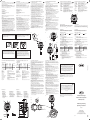
0. Einführung 0. Introduction Lesen Sie die Bedienungsanleitung sorgfältig durch, um das Messgerät in vollem Umfang nützen zu können. Please read these operating instructions carefully to ensure optimal usage of this measuring instrument. Änderungen sowohl am Messgerät als auch am Inhalt dieser Bedienungsanleitung behalten wir uns vor. We reserve the right to make modifications to the measuring instrument as well as to the contents of these instructions. Lieferumfang Standard accessories • Induktiver Feinzeiger • Steckernetzteil • Gummibalg • Schlüssel für Vorhubeinstellung • Abnahmeprotokoll • Kunststoffetui • Inductive Dial Comparator • mains adapter • rubber bellow • spanner for preliminary stroke setting • inspection certificate • plastic case Warnhinweis: Achten Sie darauf, dass nur das OriginalSteckernetzteil verwendet wird. Warning: Please use only the provided original mains adapter. Hinweise Bitte beachten Sie die folgenden Hinweise um Beschädigungen bzw. Fehlfunktionen des Messgeräts auszuschließen: •Beachten Sie die Lager- und Arbeitstemperatur des Geräts (siehe technische Daten). •Setzen Sie das Messgerät keiner elektrischen Spannung (z.B. durch elektrisches Signiergerät, etc.) aus. •Beschädigen bzw. modifizieren Sie das Gerät nicht. •Datenausgang bzw. Netzteilanschluss verschließen, wenn diese nicht benützt werden. •Das Messgerät ist bei Verwendung des Gummibalgs zur Abdichtung der Messbolzenführung spritzwassergeschützt (IP 54 nach IEC 60529). •Das Messgerät ist in einer Messuhrhalterung oder entsprechenden Vorrichtung zu betreiben. Empfohlen wird eine mit einem Schlitz versehene Halterung mit Aufnahmebohrung 8 H7 mm. • Säubern Sie die Frontabdeckung / Klarsichtscheibe mit einem weichen mit neutralem Reinigungsmittel angefeuchteten Tuch. Verwenden Sie niemals organische Lösungsmittel wie Verdünnung und Benzin. Reinigen Sie den Messbolzen mit einem in Alkohol angefeuchteten Tuch. Kein Öl auf dem Messbolzen aufbringen! Important information Please note the following to prevent damage and/or malfunction of the measuring instrument: • Please observe the storage and working temperature of this instrument (see Technical data). • Do not subject the instrument to an electrical voltage (i.e. from an electric marking unit, etc.). • Do not damage and/or modify the instrument. • Keep the data ouput as well as the socket for the charger lead covered when these are not in use. • This instrument is splash water-proof when using the rubber bellows for sealing the measuring spindle guide (IP 54 acc. IEC 60529). • The measuring instrument has to be used in a mounting device or other suitable fixture. We recommend a device with a split mounting bore of dia. 8 H7 mm. • For cleaning of the front cover/dial glass use a soft cloth moistened with a neutral reacting cleaning agent. Never use organic solvents like thinners and petrol. For cleaning of the measuring spindle use a cloth moistened with alcohol. Do not apply oil on to the measuring spindle! 2. Preparing the Inductive Dial Indicator 2.1 Spannungsversorgung 2.1 Power supply – Steckernetzteil (11) an das Wechselspannungsnetz (230/120 V) und das Kabel an die Buchse (6) anschließen. – Plug the mains adapter (11) into your mains (230/120 V) and the cable into the socket (6). 2.2 Einstellen des drehbaren Anzeige- und Bedienteils 2.2 Adjusting the rotatable operating and display unit Gehäuseoberteil ist von +90° bis -180° drehbar (2.2). Achtung: Wird das Display über die Anschlagpunkte A gedreht kann dies zur Beschädigung des Messgeräts führen! The display can be rotated from +90° to -180° (2.2). Attention: Turning the display past the stops A can lead to damage of the instrument! 2.3 Anbringen von Abhebeeinrichtungen 2.3 Mounting of the lifting devices 2.3a) Abhebung mit Drahtabheber (Zubehör 4346010) – Abdeckschraube (10) mit Münze entfernen – Handabhebung (2.3a) in das Gehäuse einschrauben – Messbolzen in das Gehäuse eindrücken, bis ein deutliches Klicken zu hören ist – Ggf. Drahtabheber in die Handabhebung einschrauben. – Ausbau erfolgt in umgekehrter Reihenfolge. 2.3a) Manual lift with Cable release (Accessory 4346010) – Remove the cover screw (10) by using a coin – screw the manual lift into the housing (2.3a) – push the measuring spindle into the housing until a definite click can be heard. – In the event of a cable release being used it is necessary to screw the cable release lead into the manual lift. – Disassemble in reverse order. 2.3b) Pneumatische Abhebung (Zubehör 4346011) 2.3b) Pneumatic lift (Accessory 4346011) – Abdeckschraube (10) mit Münze entfernen – Abhebung (2.3b) in das Gehäuse einschrauben – Messbolzen in das Gehäuse eindrücken, bis ein deutliches Klicken zu hören ist. – Ausbau erfolgt in umgekehrter Reihenfolge. Hinweis: Für die Abhebung ist ein Überdruck von 5 bis 8 bar erforderlich. Zudem muss die Luft ölfrei und gefiltert sein. – Remove the cover screw (10) by using a coin – screw the pneumatic lift into the housing (2.3b) – push the measuring spindle into the housing until a definite click can be heard. – Disassemble in reverse order. Note: For lift-off a pressure of 5 to 8 bar is required. The air must be fat free and filtered. 2.4 Anbringen der Messkrafteinstellung (Zubehör 4346012) – Abdeckschraube (10) mit Münze entfernen – Messkrafteinstellschraube in Gehäuse einschrauben bis schwarzer Dichtring nicht mehr sichtbar ist (halbe Messkraft). Durch weiteres Einschrauben wird die Messkraft erhöht. Hinweis: Messkraft ist von verwendeter Feder abhängig. 2.4 Attaching the device for setting the measuring force (Accessory 4346012) – Using a coin undo the cover screw (10). – Screw the measuring force setting screw into the housing until the black sealing ring is no longer visible (half of measuring force). Turning the screw further increases the measuring force. Note: Measuring force is dependent upon which spring is being used. 2.5 Austausch der Messkraftfeder – Abdeckschraube (10) mit Münze entfernen – Messkraftfeder entfernen und gegen gewählte ersetzen. Hinweis: Es sind Messkraftfedern zwischen 0,25 N und 2,5 N erhältlich. 2.5 Exchange of the measuring force spring – Remove the cover screw (10) by using a coin – remove the measuring force spring and exchange it for the spring that provides the required the measuring force. Note: Measuring force springs are available between 0,25 N and 2,5 N. +90° 2.2 Dieses Messgerät entspricht der Niederspannungsrichtlinie 2006/95/EG und der Richtlinie über die elektromagnetische Verträglichkeit 2004/108/EG. This measuring instrument conforms to the Low Voltage Directive 2006/95/EG and the Directive 2004/108/EG which concerns Electromagnetic compatibility. RANGE MAX/MIN TOL SET TOL mm/inch 11 0 30 30 0.00I mm PRESET DATA 0 A RESET ABS SET Millimess 2100 -180° 6 A 2.3 10 RANGE mm/inch 2.3a 0 30 30 0.00I mm ABS PRESET ABS 0 RESET SET TOL RANGE MAX/MIN SET TOL ON/OFF mm/inch 0 30 Old electronic equipment of the type Millimess 2100 which where brought from Mahr after the 23. March 2006 can be returned to us for disposal. We will dispose/recycle our products without causing any harm or damage to the environment in accordance to the EU-Directives 2002/95/ EC RoHS (the Restriction of the use of certain Hazardous Substances) and 2002/96/EC WEEE (Waste Electrical and Electronic Equipment) as well as German National - Electrical and Electronic Equipment Act, FRG. 1. Techn. Daten, Lieferumfang und Bezeichnungen 1. Technical data, standard accessories and designations Technische Daten Technical Data Anzeige-Fehlergrenze* bereich der innerhalb mm (inch) ±0,8mm1,4mm Meas. Resolution range switchable switchable display mm(inch) mm/inch Display range Span of error* of analog within mm (inch) ±0,8mm 1,4mm ±1,0 (.04”) 0,0005/.00002” ± 0,015 (.0006”) 0,001/.00005” ± 0,030 (.0015”) 1µm 2µm ±1,4 (.55”) 0,005/.0002” ± 0,150 (.0060”) 0,01/.0005” ± 0,300 (.0150”) ±1,0 (.04”) 0,0005/.00002” ± 0,015 (.0006”) 0,001/.00005” ± 0,030 (.0015”) 1µm 2µm ±1,4 (.55”) 0,005/.0002” ± 0,150 (.0060”) 0,01/.0005” ± 0,300 (.0150”) * + 1 Ziffernschritt * + 1 resolution Freihub nach oben 1,8 mm Gesamthub 4,6 mm Messkraft 0,7-0,9 N (mit Standardfeder) Messsysteminduktiv Anzeige LCD, Ziffernhöhe 6,5 mm mit grüner bzw. roter Hintergrundbeleuchtung Schutzart IP 54 nach IEC 529 bei Einsatz mit Gummibalg Betriebstemperatur +5° C bis +40° C Lagertemperatur –10° C bis +60° C Datenausgang RS232C kompatibel über Interface- kabel mit Optokoppler, USB oder Digimatic Gewicht 170 g Bestell-Nr. 4346200 (230 V), 4346201 (120 V) Free stroke Total stroke Measuring force Measuring system Display Class of protection Operating temperature Storage temperature Data output Weight Order no. upwards 1,8 mm 4,6 mm 0,7-0,9 N (with standard spring) inductive LCD, height of digits 6,5 mm, with a green resp. red backlit display IP 54 acc. IEC 529 when used with rubber bellows +5° C to +40° C –10° C to +60° C RS232C compatible via interface- cable with opto-coupler; USB or Digimatic 170 g 4346200 (230 V), 4346201 (120 V) Designations Bezeichnungen 1 Bedientasten 2 Anzeige 3 Einspannschaft 4 Messbolzen 5 Messeinsatz 6 Anschluss für Steckernetzteil 7 Datenausgang / Steuerausgang 8 Drehbares Bedien- und Anzeigeteil 9 Gummibalg 10 Abdeckschraube 11 Steckernetzteil 12 Einstellschlüssel für Vorhub 13 Vorhubeinstellschraube 14 Befestigungsöse 1085 b (Best.-Nr. 4336310) 15 Adapterbüchse 940 (Best.-Nr. 4310103) 1 Operating keys 2 Display 3 Mounting shank 4 Measuring spindle 5 Contact point 6 Socket for mains adapter 7 Data output / Control output 8 Swivelling operating and display unit 9 Rubber bellows 10 Cover screw 11 Mains adapter 12 Key for preliminary stroke setting 13 Screw for preliminary stroke setting 14 Mounting lug 1085 b (Order no. 4336310) 15 Adapter bush 940 (Order no. 4310103) 34,5 10 6 30 0.00I mm PRESET DATA 0 RESET ABS SET 2.4 Millimess 2100 2.6 Befestigung des Messgeräts Hinweis: Zur optimalen Nutzung des Messbereichs, Messgerät im ABS-Modus (3.1c) betreiben und Arbeitsbereich möglichst nahe an elektrischen Nullpunkt legen. 16 Messuhrhalterung Zur Aufnahme wird eine mit einem Schlitz versehene Halterung mit Aufnahmebohrung 8 H7 mm empfohlen (2.6a). Hinweis: Ist eine Aufnahmebohrung mit 3/8“ (9,52 mm) vorhanden, muss die Adapterbüchse 940 (4310103) verwendet werden. Wichtig! Schraube darf nicht auf den Einspannschaft drücken, damit freier Lauf des Messbolzens gewährleistet ist. Befestigungsöse 1085 b (Zubehör 4336310) Achtung: Bevor Sie die Rückwand entfernen, muss das Messgerät von der Spannungsversorgung getrennt werden! – 4 Schrauben der Geräterückwand lösen – Rückwand entfernen – Befestigungsöse anbringen (2.6b). 2.7 Austausch des Messeinsatzes Falls Einsatz nicht von Hand lösbar, – Messbolzen mit Zange festhalten. Zum Schutz der Messbolzenoberfläche ein Stück Stoff benützen – Messeinsatz mit zweiter Zange vorsichtig entfernen. Wichtig! Unvorsichtiges Handeln kann zu Schäden im Geräteinneren oder am Messbolzen führen. 2.8 Einstellen des Vorhubs – Vorhub ist mit Innensechskantschlüssel (12) im Bereich -1,4 mm bis 0* einstellbar. Hinweis: Einstellung des Vorhubs ist dann sinnvoll, wenn ein Werkstück in eine Messvorrichtung eingeführt werden soll, ohne den Messbolzen dabei manuell oder pneumatisch abzuheben. 2.3b Mounting device For mounting we recommend a device with a split mounting bore of dia. 8 H7 mm (2.6a). Note: Devices with a mounting bore of dia. 3/8“ (9,52 mm) require an adapter bush 940 (4310103). Important! In order to ensure unrestricted movement of the measuring spindle do not clamp the mounting shank directly with a screw. Mounting lug 1085 b (Accessory 4336310) Attention: Before removing the rear housing please disconnect from mains power supply! ON/OFF mm/inch 0 30 30 0.00I mm ABS ABS RESET 0 SET 23 Extramess 2001 20 21 22 Bedienung der Tasten Bei kurzem Tastendruck wird die Funktion über der Taste aktiviert, bei langem Tastendruck die Funktion unterhalb der Taste. Ausnahme: Pfeile -▲ ,- in der SET-Funktion. Operating the keys With a short press of the key the function displayed above the key will be activated, a long press will activate the function displayed below the key. Exception: in the SET-Function -▲ ,- . 3. Bedienung 3. Operation Achtung! Höchste Genauigkeit des Messgeräts wird erst nach einer Einschaltdauer von 10 min erreicht. In order to obtain highest accuracy the instrument requires at least a warm-up period of 10 minutes. Bediendauer der Tasten Duration of key activation kurz (<1 Sek.) lang (>1 Sek.) gedrückt halten short (<1 sec) long (>1 sec) hold down 3.1 Einstellfunktionen 3.1 Setting functions ON / Einschalten – Taste ON/OFF lang drücken => Das Messgerät wird eingeschaltet (in der Anzeige erscheint kurz ON). OFF / Ausschalten – Taste ON/OFF kurz drücken => Das Messgerät wird ausgeschaltet (in der Anzeige erscheint kurz OFF). Hinweis: Einstellungen (PRESET, TOL, MAX/MIN, mm/inch, ▼▲, RANGE) bleiben erhalten. ON – Long activation of ON/OFF => Switches the instrument on (after a short period of time On is shown in the display) OFF – Short activation of ON/OFF => Switches the instrument off (the display shows for a short period Off) Note: Settings (PRESET, TOL, MAX/MIN, mm/inch, ▼▲, RANGE) are retained. 3.1a) RANGE / Messbereichsumschaltung – Taste RANGE kurz drücken Ziffernschrittwert und Messbereich der Skalen- und Ziffernanzeige werden umgeschaltet. 3.1a) RANGE / Selection of measuring range – Short activation of RANGE-key Simultaneous change-over of reading and measuring range of analog- and digital display. ZiffernschrittwertMessspanne ZiffernanzeigeSkalenanzeige mm/inch mm (inch) mm (inch) 0,01/.0005” 2,8 (.11“) ± 0,300 (.015“) 0,005/.0002” 2,8 (.11“) ± 0,150 (.006“) 0,001/.00005“ 2,8 (.11“) ± 0,030 (.0015“) 0,0005/.00002“ 2,0 (.08“) ± 0,015 (.0006“) Readings mm/inch 0,01/.0005” 0,005/.0002” 0,001/.00005“ 0,0005/.00002“ mm/inch / Umschaltung der Maßeinheit – Taste mm/inch lang drücken => Symbol mm erscheint in der Anzeige. Maßeinheit mm ist aktiv. => Symbol inch erscheint in der Anzeige. Maßeinheit inch ist aktiv. mm/inch / Selection of measuring unit – Long activation of mm/inch-key => Symbol mm is displayed. mm-unit is activated => Symbol inch is displayed. inch-unit is activated 3.1b) ▲▼ / Messrichtungsumschaltung –Taste ▲▼ lang drücken =>Symbol ▲ erscheint in der Anzeige. Positive Zählrichtung bei hineingehendem Tastbolzen => Symbol ▼ erscheint in der Anzeige. Positive Zählrichtung bei herausgehendem Tastbolzen. 3.1b) ▲▼ / Selection of measuring direction – Long activation of ▲▼ => Symbol ▲ is displayed. Values increase when the spindle moves inwards => Symbol ▼ is displayed. Values increase when the spindle moves outwards Bestätigung der Rückführbarkeit Measuring span Digital display mm (inch) 2,8 (.11“) 2,8 (.11“) 2,8 (.11“) 2,0 (.08“) Analog display mm (inch) ± 0,300 (.015“) ± 0,150 (.006“) ± 0,030 (.0015“) ± 0,015 (.0006“) Wir erklären in alleiniger Verantwortung, dass das Produkt in seinen Qualitätsmerkmalen den in unseren Verkaufsunterlagen (Bedienungsanleitung, Prospekt, Katalog) angegebenen Normen und technischen Daten entspricht. Wir bestätigen, dass die bei der Prüfung dieses Produktes verwendeten Prüfmittel, abgesichert durch unser Qualitätssicherungssystem, auf nationale Normale rückführbar sind. Wir danken Ihnen für das uns mit dem Kauf dieses Produktes entgegengebrachte Vertrauen. – Undo the 4 screws on the rear of the housing – remove the cover lid – screw on the mounting lug (2.6b). 2.7 Exchange of the contact point To unscrew a tight contact point please proceed as follows: – hold the spindle tight with a pair of pliers using a piece of cloth to protect the measuring spindle from damage – use a second pair of pliers to unscrew the contact point. Important! Ignoring this advice may lead to damage of the interior of the instrument or to the measuring spindle. 2.8 Setting of the preliminary stroke – The preliminary stroke is set with the hexagon wrench (12) in the range of -1,4 mm to 0*. Note: This setting can be useful, if a workpiece is to be inserted into a measuring device without manually or pneumatically lifting up the measuring spindle. *bezogen auf elektrischen Nullpunkt * based on electrical zero position 2.9 Aktivieren der Einschaltautomatik Hinweis: Bei aktivierter Einschaltautomatik, schaltet der Millimess 2100 ein, wenn Spannung anliegt. Das Messgerät läßt sich dann nur durch Trennen der Spannungsversorgung abschalten. Beim Betätigen der OFF-Taste erscheint LOC in der Anzeige. 2.9 Activating the ON/OFF-Automatic Note: By activating the ON/OFF-Automatic the Millimess 2100 will only turn on once power is supplied, by disconnecting the power source the instrument will turn off automatically. Pressing the OFF-Key will only result in LOC being featured in the display. Achtung: Bevor Sie die Rückwand entfernen, muss das Messgerät von der Spannungsversorgung getrennt werden! Attention: Before removing the rear housing please disconnect from mains power supply! – 4 Schrauben der Geräterückwand lösen – Rückwand entfernen – DIP-Schalter (24) auf Platine mit kleinem Schraubendreher umschalten (ggf. Gehäuseoberteil verdrehen, bis DIPSchalter sichtbar wird) – Rückwand wieder mit den 4 Schrauben befestigen – Zum Deaktivieren der Einschaltautomatik den DIP-Schalter (24) erneut umschalten. – Undo the 4 screws on the rear of the housing – remove the cover lid – Switch over the Dip-switch (24) on the circuit board with a small screwdriver (if necessary rotate front housing until the Dip-switch is in view) – Re-attach rear housing with the 4 screws – To deactivate the ON/OFF-Automatic switch back the Dipswitch (24). 2.8 TOL RANGE MAX/MIN SET TOL 2.6 RANGE MAX/MIN SET TOL 2.6 Mounting of the measuring instrument Note: For optimum use of the measuring range adjust the measuring instrument while in ABS-mode (3.1c) as close as possible to the electrical zero position (middle of the measuring range). ON/OFF Änderungen an unseren Erzeugnissen, besonders aufgrund technischer Verbesserungen und Weiterentwicklungen, müssen wir uns vorbehalten. Alle Abbildungen und Zahlenangaben usw. sind daher ohne Gewähr. © by Mahr GmbH Confirmation of traceability We declare under our sole responsibility that this product is in conformity with standards and technical data as specified in our sales documents (operating instructions, leaflet, catalogue). We certify that the measuring equipment used to check this product, and guaranteed by our Quality Assurance, is traceable to national standards. Thank you very much for your confidence in purchasing this product. We reserve the right to make changes to our products, especially due to technical improvements and further developments. All illustrations and technical data are therefore without guarantee. Induktiver Feinzeiger mm/inch © by Mahr GmbH ø 8 H7 Inductive Dial Comparator 0 30 2.6a) 8,5 17 Printed in Germany Mess- Ziffernschritt bereiche umschaltbar umschaltbarSkalenanzeige mm(inch) mm/inch 30 0.00I Millimess 2100 mm ABS 7 PRESET DATA 0 RESET ABS SET Millimess 2100 1 RANGE MAX/MIN ON/OFF Operating Instructions 2.7 ø65 16 30 0.00I ø6,5 0 30 Bedienungsanleitung 16,5 mm/inch ø63 SET TOL 12 2.6b) 8 TOL 3756635 mm ABS 2 8,5 DATA 0 ABS SET 14 RESET 112,5 PRESET Millimess 2100 2.9 19 13 15 ø8h6 5 Reutlinger Str. 48, 73728 Esslingen, Tel. +49 711 9312 600, Fax +49 711 9312 756 e-mail: [email protected], www.mahr.com 10 9 6 4 Mahr GmbH Standort Esslingen 24 42 12 75,5 ø.375“ 28 3 Switches instrument on resp. off Selection of measuring range and resolution Selection of measuring unit Display of maximum-/minimum value Selection of measuring direction Monitoring of tolerance Set tolerance Call-up of the stored Preset-values resp. activation of the Preset-setting mode (SET) Displayed value will be sent via the data output Zeroing of the analog display Zeroing of the digital and analog display Shows the reference to the electrical zero of the measuring system ON/OFF 2.5 Elektrische Altgeräte der Type Millimess 2100, die nach dem 23. März 2006 durch Mahr in den Verkehr gebracht werden, können an uns zurückgegeben werden. Wir führen diese Geräte einer umweltgerechten Entsorgung zu. Die EU-Richtlinien 2002/95/EG RoHS und 2002/96/EG WEEE bzw. das ElektroG finden dabei ihre Anwendung. 18 19 ON/OFF 16ON/OFF 17RANGE/ mm/inch 18MAX/MIN/ ▼▲ 19TOL/ SET TOL 20PRESET/ SET 21DATA 22--0-- 23RESET/ ABS Ein- bzw. Ausschalten des Messgerätes Wahl des Messbereichs und der Auflösung Umschaltung der Maßeinheit Maximal-/Minimalwerterfassung Messrichtungsumschaltung Toleranzüberwachung Toleranz einstellen Abrufen des gespeicherten Presetwerts bzw. Aktivierung des Preset-Einstellmodus (SET) Angezeigten Wert über den Datenausgang senden Nullsetzen der Skalenanzeige Nullsetzen der Ziffern- und Skalenanzeige Zeigt absolute Position des Messbolzens bezogen auf elektrischen Nullpunkt des Messsystems PRESET 2.1 EC Declaration of Conformity 16ON/OFF 17RANGE/ mm/inch 18MAX/MIN/ ▼▲ 19TOL/ SET TOL 20PRESET/ SET 21DATA 22--0-- 23RESET/ ABS Designation and function of the operating keys TOL 0° EG-Konformitätserklärung Kennzeichnung und Funktion der Bedientasten ▲ The Inductive Dial Comparator Millimess 2100 is a versatile precision measuring instrument for economic application on the production line and in the inspection room. ▲ Der Induktive Feinzeiger Millimess 2100 ist ein vielseitiges Präzisionsmessgerät für den wirtschaftlichen Einsatz in der Fertigung und im Messraum. 2. Vorbereiten des induktiven Feinzeigers ø4 0614 – Taste ABS lang drücken => Symbol ABS erscheint im Display Absolute Position des Messbolzens wird angezeigt. Hinweis: Zur optimalen Nutzung des Messbereichs, Messgerät im ABS-Modus betreiben und Einstellung möglichst nahe an Nullpunkt legen. 3.1d) Faktoreinstellung – Short activation of ABS => Symbol ABS is displayed. Absolute position of the spindle is displayed Note: For optimum use of the measuring range set the measuring instrument while in ABS-mode as close as possible to the zero position (middle of the measuring range). 3.1d) 3.1d) Setting of factor 2 ON/OFF PRESET DATA RANGE MAX/MIN TOL mm/inch SET TOL RESET 0 PRESET ABS SET ON/OFF mm/inch DATA RESET 0 ABS SET RANGE MAX/MIN TOL SET TOL ON/OFF RANGE MAX/MIN TOL mm/inch SET TOL ▲ ▲ 1 ON/OFF mm/inch mm PRESET DATA RESET 0 PRESET ABS SET DATA ABS SET TOL RANGE MAX/MIN SET TOL Note: Permissable factor-range: +0,001 ... +9,999 F appears before the displayed value for any factor not being 1. If the display position for F is needed for a number (-PRESETvalue >±99.999), number and F will change in a 0,5 seconds cycle. Factor remains in memory also after switching-off resp. when the battery is empty. RESET 0 ON/OFF mm/inch 0 30 3.1e) Sperren von Bedienfunktionen 30 0.001 mm Hinweis: Nur über Konfigurationsprogramm (4346022) vom PC aus möglich. Folgende Bedienfunktionen können einzeln oder in Kombination gesperrt werden: PRESET SET Messrichtung SET PRESET ABS RANGE PRESETMAX/MIN mm/inch 0 SET TOL ON/OFFRESET TOL RANGE MAX/MIN TOL SET TOL DATA 0 3.1e) Locking of the operating functions RESET ABS ON/OFF SET TOL 30 ON/OFF mm/inch 0 Bei Aufruf einer gesperrten Funktion erscheint die Meldung LOC für 1 Sekunde in der Anzeige RANGE MAX/MIN TOL mm/inch 0 30 0.001 30 30 0.001 mm DATA 0 RESET PRESET ABS SET SET RANGE MAX/MIN TOL SET TOL mm ON/OFF DATA RANGE MAX/MIN SET TOL ON/OFF mm/inch 0 30 0 30 0.001 30 DATA 30 0.001 DATA mm PRESET DATA 0 mm RESET PRESET ABS SET SET DATA RESET 0 ABS 2 1 RANGE MAX/MIN TOL SET TOL ON/OFF SET TOL ON/OFF mm/inch 0 30 RANGE MAX/MIN TOL mm/inch 0 30 0.00I 30 30 0.00I mm PRESET DATA 0 SET mm RESET PRESET ABS SET DATA 3.2a) RESET – Taste RESET kurz drücken => Ziffern- und Skalenanzeige werden auf “0” gesetzt. Hinweis: Je nach Stellung des Tastbolzens kann der Messbereich jedoch eingeschränkt sein. ABS TOL ▲ RANGE MAX/MIN RESET PRESET ABS SET ON/OFF DATA RANGE MAX/MIN SET TOL ON/OFF mm/inch 0 15 RESET 0 ABS TOL mm/inch 0 15 0.0005 15 15 0.0005 mm mm PRESET PRESET PRESET DATA 0 SET TOL RANGE MAX/MIN SET TOL RESET PRESET ABS SET ON/OFF DATA RESET 0 ABS RANGE MAX/MIN TOL mm/inch SET TOL ON/OFF mm/inch 0 15 0 15 0.0005 15 15 0.0005 mm PRESET DATA 0 RESET PRESET ABS SET SET DATA RESET 0 ABS 3.2d) TOL RANGE MAX/MIN SET TOL ON/OFF TOL mm/inch 0 30 0.001 DATA 0 RANGE MAX/MIN SET TOL MIN PRESET ABS SET ON/OFF TOL mm/inch DATA 30 DATA 0 RANGE 30 mm/inch MAX-MIN PRESET ABS SET ON/OFF TOL mm/inch DATA DATA mm RESET ABS RANGE MAX/MIN ON/OFF 0 30 30 0.001 mm mm RESET PRESET ABS SET DATA 0 3.2d) MAX / MIN / MAX-MIN – Short activation of MAX/MIN-key => registration of maximum value: Symbol MAX appears in the display. During measuring the highest value is shown in the digital and analog display and stored (maximum indicator function). – activation of RESET-key starts new measuring cycle. – repeated activation of MAX/MIN-key => registration of minimum value: Symbol MIN appears in the display. During measuring the highest value is shown in the digitaland analog display and stored. – activation of RESET-key starts new measuring cycle. – repeated short activation of MAX/MIN-key => registration of difference value: Symbol MAX-MIN appears in the display. Digital- and analog display shows “0”. During measuring the MAXIMUM- and the MINIMUM-value is stored and the difference computed. The same is is shown in the digital- and analog display and stored. – activation of RESET-key starts new measuring cycle. – repeated activation of MAX/MIN-key Symbol MAX-MIN is cleared and the instrument is again ready for normal operation. Note: In MIN, MAX, MAX-MIN -mode the following functions are locked: mm/inch 0 30 MAX-MIN SET 0 SET TOL 0.001 PRESET 30 mm 0 30 ON/OFF 0.001 RESET SET SET TOL RANGE MAX/MIN 0 MAX-MIN MAX/MIN RESET 0 SET TOL 0.001 TOL mm ABS 0 30 30 0.001 RESET SET TOL 30 mm MAX PRESET ON/OFF mm/inch 0 30 RANGE MAX/MIN SET TOL 3.2c) PRESET Entering the PRESET – Long activation of PRESET-key => Symbol PRESET is displayed, ‘+’ resp. ‘–’ flashes SET-mode is active – Short activation of key - ▲ => Sign (+ ... –) changes resp. digit moves up with each key activation (0,1,2 ... 9) – Short activation of key - => Next digit flashes – Repeat procedure to set the next digit. Activation of RESET-key sets chosen digit to zero. – Short activation of PRESET-key => Symbol PRESET disappears. The entered PRESET value is stored and simultaneously activated. Note: PRESET-value and PRESET-position are retained after switch-off PRESET activation – Short activation of PRESET- key => The stored PRESET-value appears as actual value on the display. Attention: If the resolution has been changed then the Preset value will be rounded according to those digits shown on the display! Note: Check whether the measuring direction (3.1b) is set correctly for your application. Functions RESET, --0--, PRESET will be executed with approx. 250 ms delay after release of the key in order not to be affected by the pressing of the key. mm PRESET PRESET 3.2b) --0-– Short activation of 0-key => Sets analog display to zero and retains the value shown by the digital display mm PRESET RESET ABS TOL/SET-TOL ▼▲ mm/inch PRESET/SET ABS 0 MAX, MIN, MAX-MIN remain in memory even after switching off resp. when the battery is empty. When the instrument is switched on the value of the display is set to the actual position (MAX, MIN) resp. to “0” (MAX-MIN). => exceeding the range is signaled in the analog display by the symbol . ▲ Übernahme des Einstell- bzw. Meisterwerts im Extrempunkt. Bei aktivierter MAX- bzw. MIN- Funktion kann eine Übernahme des Preset-Werts erfolgen. – Nach Ermittlung des Extremwerts wird kurz die PRESET- Taste betätigt. => Zur Bestätigung erscheint kurzzeitig der gespeicherte Preset-Wert in der Anzeige. – MAX, MIN durch mehrmaliges Betätigen der MAX/MIN- Taste verlassen. – Nach erneuter Anwahl von MAX bzw. MIN erscheint an der Stelle des Maximums, bzw. Minimums der gespeicherte Preset-Wert. 0 15 0.0005 3.2a) RESET – Short activation of RESET-key => Sets digital and analog display to zero Note: Due to the position of the measuring spindle the range may be limited. ▲ ▲ Bereichsüberschreitung wird in der Skalenanzeige durch das Symbol angezeigt. DATA SET ▲ MAX, MIN, MAX-MIN bleiben auch nach dem Ausschalten erhalten. Beim Einschalten wird der Anzeigewert auf die aktuelle Position (MAX, MIN) bzw. auf “0” (MAX-MIN) gesetzt. 15 mm PRESET 0 0 15 PRESET SET TOL ON/OFF mm/inch 0 – Taste MAX/MIN nochmals kurz drücken. Symbol MAX-MIN erlischt und das Messgerät befindet sich wieder im Normalmodus. TOL/SET-TOL ▼▲ mm/inch PRESET/SET ABS SET TOL 0.0005 PRESET RANGE MAX/MIN TOL ON/OFF mm/inch 15 PRESET aktivieren – Taste PRESET kurz drücken => Gespeicherter PRESET-Wert erscheint als aktueller Wert in der Anzeige. Achtung: Wird der Ziffernschrittwert geändert, wird der Presetwert entsprechend der Stellen in der Anzeige gerundet übernommen! Hinweis: Achten Sie darauf, dass die Zählrichtung (3.1b) für Ihre Anwendung richtig gesetzt wurde. Die Funktionen RESET, --0--, PRESET werden nach dem Loslassen der Taste um ca. 250 ms. verzögert ausgeführt, um einen Einfluß des Anwenders durch das Drücken der Taste zu vermeiden. Hinweis: In MAX, MIN, MAX-MIN - Modus sind folgende Funktionen gesperrt: RANGE MAX/MIN TOL 3.2c) PRESET PRESET eingeben – Taste PRESET/SET lang drücken => Symbol PRESET erscheint in der Anzeige, + bzw. – blinkt. SET-Modus ist aktiviert – Taste - ▲ kurz drücken => Vorzeichen (+ ... –) wechselt bzw. Anzeigestelle erhöht sich bei jedem Tastendruck (0.1.2 ... 9) – Taste - kurz drücken => Nächste Anzeigestelle blinkt – Zum Setzen der nächsten Anzeigestelle den Vorgang wieder holen. Taste RESET setzt angewählte Anzeigestelle auf “0” – Taste PRESET kurz drücken => Symbol PRESET wird ausgeblendet. Eingegebener PRESET-Wert wird gespeichert und gleichzeitig aktiviert Hinweis: PRESET-Wert und PRESET-Position bleiben auch beim Ausschalten erhalten. 3.2d) MAX / MIN / MAX-MIN – Taste MAX/MIN kurz drücken => Maximalwerterfassung: Symbol MAX erscheint in der Anzeige. Beim Messen wird in der Ziffern- und Skalenanzeige der höchste Wert angezeigt und gespeichert (Schleppzeigerfunktion). – Druck auf RESET-Taste startet neue Messung. – Taste MAX/MIN nochmals kurz drücken => Minimalwerterfassung: Symbol MIN erscheint in der Anzeige. Beim Messen wird in der Ziffern- und Skalenanzeige der niedrigste Wert angezeigt und gespeichert. – Druck auf RESET-Taste startet neue Messung. – Taste MAX/MIN nochmals kurz drücken => Differenzwerterfassung: Symbol MAX-MIN erscheint in der Anzeige. Ziffern- und Skalenanzeige stehen auf “0”. Beim Messen werden der MAXIMAL- und der MINIMAL-WERT gespeichert und die Differenz ermittelt. Diese wird in der Ziffern- und Skalenanzeige angezeigt und gespeichert. – Kurzer Druck auf RESET-Taste startet neue Messung. 3.2 Measuring functions SET TOL 3.2b) --0-– Taste --0-- kurz drücken => Skalenanzeige wird auf “0” gesetzt. Anzeigewert der Ziffernanzeige bleibt erhalten. – Long activation of DATA-key and hold, short activation of the RESET-key => Symbol DATA appears in display, the displayed measuring values are continuously transmitted via the interface. Press DATA-key again to stop data transmission (approx. 35 ... 39 values/sec.). RESET 0 3.2c) 3.2 Messfunktionen 3.1f) DATA Note: The DATA-key only operates with a OPTO RS232C or USB data cable! – Short activation of DATA-key =>Symbol DATA appears briefly in the display, the displayed value is transmitted via the interface. – Long activation of DATA-key => Symbol DATA appears in display, the displayed measuring values are continuously transmitted via the interface as long as the DATA-key is pressed (approx. 35 ... 39 values/sec.). Acceptance of the setting- resp. master value in the extreme point position. An active MAX- resp. MIN-function permits the acceptance of the Preset-value. – After determination of the extreme value please execute a short activation of the PRESET-key. => For confirmation the stored Preset-value appears for a moment in the display. – Exit MAX, MIN by repeated activation of the MAX/MIN-key. – After renewed selection of MAX resp. MIN the stored Presetvalue appears instead of the maximum resp. minimum. TOL RANGE MAX/MIN SET TOL ON/OFF TOL mm/inch RANGE MAX/MIN SET TOL ON/OFF mm/inch 0 30 0 30 0.001 ABS PRESET SET TOL mm SET TOL ▲ RESET 0 30 0.001 mm SET TOL ▲ PRESET 30 0 RESET RANGE ON/OFF ABS SET RANGE MAX/MIN SET TOL ON/OFF TOL mm/inch MAX/MIN SET TOL mm/inch 0 30 0 30 0.001 ABS PRESET SET Hinweis: Toleranzwerte werden als Absolutwert eingegeben: TOL RANGE MAX/MIN ON/OFF TOL mm/inch MAX/MIN SET TOL 30 0.001 PRESET RANGE ON/OFF Note: Tolerance values are entered as absolute values: i. e.: 8 ± 0.025 => Value for Set, Tol,▲: 8.025 Value for Set, Tol,▼: 7.975 Short activation of TOL/SET TOL key, Tolerance monitoring is active. Note: Error report ERR – upper tolerance value may not be ≤ than lower tolerance value. – The tolerance band may not be >2,8 mm (Please re-enter new tolerance limits). 0 30 30 0.001 mm SET TOL ▼ Hinweis: Fehlermeldung ERR – Oberer Grenzwert darf nicht ≤ unterem Grenzwert sein. – Toleranzband darf nicht >2,8 mm sein (Toleranzgrenzen neu eingeben) RESET mm/inch 0 30 0 ABS SET SET TOL z. B.: 8 ± 0.025 => Wert für Set, Tol,▲: 8.025 Wert für Set, Tol,▼: 7.975 Taste TOL/SET TOL kurz drücken, Toleranzüberwachung ist aktiv. mm SET TOL ▲ RESET 0 30 0.001 mm SET TOL ▲ PRESET 30 mm TOL ABS RESET 0 PRESET SET ABS RESET 0 TOL activate/deactivate tolerance SET – Short activation of the TOL/SET TOL-key => Tolerance markers appear in the analog display Sand the symbol TOL in the general display. The symbol for the scale divisions disappears => readings from the analog scale decoupled – Repeated short activation of the TOL/SET TOL-key => Tolerance markers and symbol TOL are being blanked out. TOL: Toleranz aktivieren/deaktivieren – Taste TOL kurz drücken => Toleranzmarken in der Skalenanzeige und Symbol TOL erscheinen in der Anzeige. Symbol für Skalenteilung verschwindet => Ziffernschrittwert der Skalenanzeige ist abhängig vom eingestellten Toleranzwert. – Taste TOL nochmals kurz drücken => Toleranzmarken und Symbol TOL werden ausgeblendet. Note: The following functions are locked: ▼▲ mm/inch ABS ▼▲ mm/inch ABS 0 MAX/MIN OL zeigt an, dass sich das Messgerät außerhalb des Messbereiches befindet. Symbole bzw. an den Enden der Skalenanzeige und die rot leuchtende Hintergrundbeleuchtung zeigen Toleranzüberschreitung an. Befindet sich die Marke des aktuellen Messwerts direkt auf einer der Toleranzmarken der Skalenanzeige, so blinkt die entsprechende Marke. Messbereich der Skalenanzeige ist von den eingegebenen Toleranzen und vom Ziffernschrittwert abhängig z.B. bei Ziffernschrittwert 0,001 mm: ±0,015 mm ±0,03 mm 0,0005 mm 0,001 mm <= 2,8 mm ±1,8 mm 0,060 mm <= .01672“ <= .03352“ ± .009“ ± .018“ .0003“ .0006“ <= .11180“ ± .060“ .002“ . . . . . . . . . . . . Tolerance band Measuring range Analog display <=0,027 mm <=0,055 mm ±0,015 mm ±0,03 mm 0,0005 mm 0,001 mm <= 2,8 mm ±1,8 mm 0,060 mm <= .01672“ <= .03352“ ± .009“ ± .018“ .0003“ .0006“ <= .11180“ ± .060“ .002“ . . . Toleranzband MessbereichSkalenteilung Skalenanzeige <=0,027 mm <=0,055 mm MAX/MIN 0 OL indicates that the measuring instrument operates outside the measuring range. Symbols resp. at the ends of the analog display and the red backlit display indicate that the tolerances are exceeded. When the marker of the actual measuring value is directly on one of the tolerance markers of the analog display, the respective marker will flash. The measuring range of the analog display is dependant upon the entered tolerances and resolution, for example e.g. resolution 0,001 mm Hinweis: Folgende Funktionen sind gesperrt: ▲ –Taste DATA lang drücken und halten, Taste RESET kurz drücken, beide Tasten loslassen. => Symbol DATA erscheint im Display. Der angezeigte Messwert wird kontinuierlich über die Schnittstelle übertragen. Taste-DATA erneut zum Stoppen der Übertragung drücken (ca. 35 ... 39 Werte/Sek.). When a locked function is called up the report LOC will appear in the display for 1 second. ABS TOL mm/inch RESET 0 Measuring direction SET PRESET ABS RANGE PRESETMAX/MIN 0 mm/inch SET TOL ON/OFFRESET TOL – Long activation of the TOL/SET TOL-key => Symbols SET, TOL, ▲ appear in the display + resp. – flashes in the display. => SET-mode for the upper limit value is active. – short activation of the ▲-key => Sign (+...–) changes resp. displayed digit increases each time the key is activated (0.1.2 ... 9) – short activation of the -key => next display position flashes – repeat procedure to set the next displayed digit. Using the RESET-key sets each digit to “0”. – Short activation of the TOL/SET TOL-key => Symbols SET, TOL, ▼ appear in the display + resp. – flashes in the display. => SET-mode for lower limit value is active. – short activation of the ▲-key => Sign (+...–) changes resp. displayed digit increases each time the key is activated (0.1.2 ... 9) – short activation of the -key => next display position flashes – repeat procedure to set the next display digit. Using the RESET-key sets each numerical digit to “0”. 3.2e) ▲ 3.1f) DATA Hinweis: Die DATA-Taste funktioniert nur mit den OPTO RS232C oder USB Datenkabeln! –Taste DATA kurz drücken =>Symbol DATA erscheint kurz im Display und der angezeigte Messwert wird über die Schnittstelle übertragen. –Taste DATA lang drücken => Symbol DATA erscheint im Display und der angezeigte Messwert wird kontinuierlich über die Schnittstelle übertragen, solange die DATA-Taste gedrückt wird (ca. 35 ... 39 Werte/Sek.). PRESET Note: Only possible from the configuration programme of the PC (4346022). The following operating functions can be locked individually or in combination: ▲ Hinweis: Zulässiger Faktor-Bereich: +0,001 ... +9,999 Ist der Faktor ungleich 1 erscheint vor dem Anzeigewert ein F. Wird die F-Anzeigestelle für eine Ziffer benötigt (PRESETWert >±99.999), so wechselt Ziffer und F im 0,5 SekundenTakt. Faktor bleibt auch nach dem Ausschalten erhalten. – Taste SET TOL lang drücken => Symbole SET, TOL, ▲ erscheinen in der Anzeige + bzw. – blinkt => SET-Modus für oberen Grenzwert ist aktiv. – Taste - ▲ kurz drücken => Vorzeichen (+ ... –) wechselt bzw. Anzeigestelle erhöht sich bei jedem Tastendruck (0,1,2 ... 9) – Taste - kurz drücken => Nächste Anzeigestelle blinkt – Vorgang wiederholen, um die nächste Anzeigestelle zu setzen. Mit Taste RESET kann jede Anzeigestelle auf “0” gesetzt werden. – Taste TOL/SET TOL kurz drücken => Symbole SET, TOL, ▼ erscheinen in der Anzeige + bzw. – blinkt. => SET-Modus für unteren Grenzwert ist aktiv. – Taste - ▲ kurz drücken => Vorzeichen (+ ... –) wechselt bzw. Anzeigestelle erhöht sich bei jedem Tastendruck (0.1.2 ... 9) – Taste - kurz drücken => Nächste Anzeigestelle blinkt – Vorgang wiederholen, um die nächste Anzeigestelle zu setzen. Mit Taste RESET kann jede Anzeigestelle auf “0” gesetzt werden. SET Tol: Set tolerance ▲ 30 0.001 SET: Toleranz einstellen ▲ 0 30 – Switch-off the instrument – activate the RESET-key and keep it depressed – short activation of ON/OFF-key => Symbol F and current factor will be displayed. The pre-comma position flashes SET-mode for factor is active. – short activation of ▲-key => display position advances everytime the key is pressed (0.1.2 ... 9) – short activation of -key => next display position flashes. To set the next display position repeat the procedure. RESET-key resets the last selected numerical digit to “0” – short activation of PRESET-key => factor will be accepted. 3.2e) TOL/Tolerance monitoring ▲ RANGE MAX/MIN TOL SET TOL 3.2e) TOL/Toleranzüberwachung ▲ – Messgerät ausschalten – Taste RESET gedrückt halten – ON/OFF-Taste drücken => Symbol F und aktueller Faktor wird angezeigt. Vorkommastelle blinkt SET-Modus für Faktor ist aktiv. – Taste - ▲ kurz drücken => Anzeigestelle erhöht sich bei jedem Tastendruck (0.1.2 ... 9) – Taste - kurz drücken => Nächste Anzeigestelle blinkt. Zum Setzen der nächsten Anzeigestelle den Vorgang wiederholen. Taste RESET setzt angewählte, Zahlenstelle auf “0” – Taste PRESET kurz drücken => Faktor wird übernommen. => ▲ 3.1c) ABS ▲ 3.1c) ABS . . . . . . . . . Readings . . . . . . . . . . . . 4. Displaymeldungen 4. Display reports 4.1 OL / Messbereichsüberschreitung => Messbolzenposition außerhalb des Messbereichs. 4.2 LOC / Bedientaste gesperrt => ggf. Taste am PC mit LOC-Software entsperren. – LOC nur beim Abschalten (siehe Kapitel 2.9) . Ggf. Einschaltautomatik deaktivieren. TOL RANGE MAX/MIN SET TOL 4.2 LOC / Operating keys locked => if need be key on PC with LOC-Software unlock. – LOC only by switch-off (see chapter 2.9). if required: de-activate ON/OFF-Automatic. ON/OFF mm/inch 0 4.3 F / Faktor ist eingegeben => ggf. Faktor ändern oder zurücksetzen (siehe 3.1d) 30 4.3 F / Factor is entered => change factor or reset (see 3.1d) 30 0.00I mm ABS 4.4 ERR / Toleranzeingabe nicht korrekt – Das Toleranzband darf nicht >2,8 mm sein – oberer Grenzwert darf nicht ≤ unterem Grenzwert sein. Bitte Toleranzgrenzen neu eingeben. 5. Schnittstelle 4.1 OL / Measuring range exceeded => Position of measuring spindle outside of range. 4.1) PRESET ABS 0 4.4 ERR / Tolerance input incorrect – The tolerance band may not be >2,8 mm – upper tolerance value may not be ≤ than lower tolerance value. Please re-enter new tolerance limits. RESET SET Hinweis: Gerät vor Anschluss eines Kabels ausschalten! Sonst erfolgt keine automatische Kabelerkennung. 5.1 Digimatic Datenkabel Achtung! Bei Digimatic-Schnittstellen können nur 6 Dezimalstellen übertragen werden. Bei 7-stelliger Anzeige wird die höchste Dezimalstelle nicht übertragen. 5.2 Opto RS232C Datenkabel Ausführliche Beschreibung der Duplex-Befehle auf Anforderung. 5.3 USB Virtueller COM-Schnittstellentreiber Der Treiber emuliert für jedes angeschlossene Kabel einen D2xx-Treiber und zusätzlich einen virtuellen Com-Port über den das Messgerät im Opto RS232 Duplex Modus angesteuert werden kann. Über den D2xx Treiber kann auch direkt über eine DLL auf die Schnittstelle des Messgeräts zugegriffen werden (siehe D2xx Programmer’s Guide auf CD). Note: Please switch off the measuring instrument before connecting a cable, otherwise the automatic cable detection will not function. 5.1 Digimatic Data cable Attention! Digimatic-interfaces can only transmit 6 digits. 7-digit displays do not show the highest decimal place. 5. Interface ¡ ¢ £ ¤¤ ¥ ¦ ¢ ¤ ¢ § ¨ 5.2 Opto RS232C Data cable Detailed description of Duplex commands available on demand. 5.3 Virtual COM-Interface-Driver The driver emulates for every connected cable a D2xx driver and additional a virtual COM-Port which can be controlled via the measuring instrument in the Opto RS232 Duplex mode. With the D2xx driver a DLL can also be directly accessed via the interface on the measuring instrument (see D2xx Programmer’s Guide on the CD). Lieber Kunde Dieses Gerät enthält einen Nickel-Metallhydrid-Akku (wiederaufladbar) Lässt sich der Akku nicht mehr aufladen, darf er nicht im Hausmüll entsorgt werden! Akkumulatoren enthalten möglicherweise Schadstoffe, die Umwelt und Gesundheit schaden können. Bitte geben Sie den Akku im Handel oder an den Recyclinghöfen der Kommunen ab. Die Rückgabe ist unentgeltlich und gesetzlich vorgeschrieben. Bitte werfen Sie nur entladene Akkumulatoren in die aufgestellten Behälter. Alle Akkumulatoren werden wieder verwertet. So lassen sich wertvolle Rohstoffe wie Eisen, Zink oder Nickel wieder gewinnen. Batterierecycling dient dem Umweltschutz. Dear Customer The measuring instrument contains a rechargeable nickel-metal hydride battery. If the accumulator can no longer be charged, it may not be disposed of in the household waste! Spent accumulators contain toxic waste which can cause harm to the environment and cause damage to health. Spent batteries and accumulators either must be returned to an outlet where batteries or accumulators are sold, or taken to a municipal collection point, these have an (unpaid) and legal obligation to take back batteries. Please only dispose of spent batteries in the provided collection containers, when disposing Lithium batteries please cover up the Poles. All batteries can be recycled; raw materials such as iron, zinc or nickel can be obtained from recycled batteries, thus battery recycling helps with the protection of the environment.