1
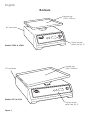
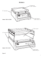
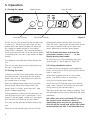
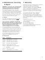
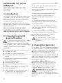
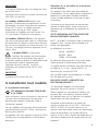
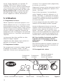
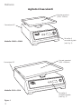
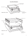
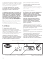
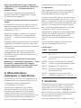
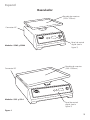
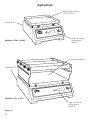
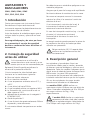
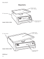
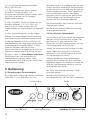
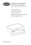
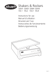
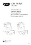
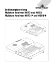
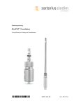
Shakers & Rockers
SSM1 SSM3 SSM4 SSM5
SSL1 SSL2 SSL3 SSL4
Instructions for use
Manuel d’utilisation
Istruzioni per l’uso
Instrucciones de funcionamiento
Bedienungsanweisung
Version 1.0
English
Rockers
Sample tray
(235 x 235mm)
IEC connector
Model: SSM3 & SSM4
IEC connector
Digital control
panel (see fig. 3)
Sample tray
(355 x 355mm)
Model: SSL3 & SSL4
Digital control
panel (see fig. 3)
Figure 1
Shakers
Sample tray
(220 x 220mm)
IEC connector
Model: SSM1 & SSM5
Digital control
panel (see fig. 3)
Cradle system
IEC connector
Model: SSL1 & SSL2
Digital control
panel (see fig. 3)
Figure 2
1
SHAKERS & ROCKERS
SSM1, SSM3, SSM4, SSM5, SSL1, SSL2,
SSL3, SSL4
1. Introduction
Thank you for purchasing this piece of Stuart
equipment. To get the best performance from the
equipment please read these instructions carefully
before use.
Before discarding the packaging check that all
parts are present and correct.
For your own safety and that of others
please read and understand the safety advice
given below before using the equipment.
2. Safety Advice before use
If the equipment is not used in the manner
described in this manual and with
accessories other than those recommended by
Barloworld Scientific the protection provided
might be impaired.
This equipment is designed to operate under the
following conditions: ❖
❖
❖
❖
❖
❖
❖
❖
❖
For indoor use only
Use in a well ventilated area
Ambient temperature range +5°C to +40°C
Altitude to 2000m
Relative humidity not exceeding 80%
Mains supply fluctuation not exceeding 10%
Over-voltage category II IEC60364-4-443
Pollution degree 2
Use with a minimum distance all around of
200mm from walls or other items
The unit should be carried using both hands.
Do not use in a hazardous atmospheres or with
hazardous materials.
Ensure that the load is balanced.
Do not attempt to stop movement by hand.
Never move or carry the unit when in use or
connected to the mains electricity supply.
2
In the case of mains interruption, the unit will
not restart on restoration of the electricity supply.
In the case of mechanical interruption, (e.g.
motor stall), the unit will continue operating on
removal of interruption.
Mechanical energy can lead to breakage of glass
vessels. Use with care.
Mechanical hazard SSL2. Cradle to be
assembled onto platform before
operating.
3. General Description
Stuart shakers and rockers are ideal instruments
for mixing and aerating various biological and
chemical samples in the laboratory. All models
have digital setting of both speed and time up to
999 minutes. The SSM range comprise of
personal units with a small footprint while the
SSL is the larger labscale equivalent.
Model SSM1 and SSL1 provides a smooth
uniform circular motion with an orbit of 16mm.
Speed range is 30 to 300rpm. Max load 3kg and
10kg respectively.
Model SSL2 has a side-to-side
reciprocating action ideal for vigorous
shaking applications. Speed range is 25 to
250rpm. Max load 10kg*.
IMPORTANT
* Maximum speed with 10kg load is 200rpm.
Maximum load for a speed setting of 250rpm is
5kg.
Model SSM3 and SSL3 provides a 3D gyratory
motion, ideal for low foaming agitation, DNA
extractions, staining and de-staining procedures
etc. Speed range is 5 to 70 rpm. Max load 3kg
and 10kg respectively. The angle of tilt can be
adjusted manually, without the need for tools,
between 3 and 12° (see section 4.6 for
instructions).
Model SSM4 and SSL4 have a see-saw rocking
action that creates a wave motion within vessels
such as culture flasks, Petri dishes etc. Speed
range is 5 to 70 rpm. Max load 3kg and 10kg
respectively.
Model SSM5 is designed for use with
microtitre plates and microcentrifuge
tubes. High speed combined with a tiny orbit
creates the vibrational shaking action required
for mixing very small volumes. Speed range is
250 to 1,200 rpm.
IMPORTANT Maximum load is 1kg.
4. Preparation for Use –
All models
4.1 Electrical Installation
THIS INSTRUMENT MUST BE
EARTHED
Before connection please read and understand
these instructions and ensure that the line supply
corresponds to that shown on the rating plate.
All models are designed for use on 230V 50Hz.
The power consumption of each unit is 50W.
The instruments are fitted with an IEC socket at
the rear of the instrument for connection of the
mains lead.
Caution: Fuses fitted in both live and
neutral lines.
These units are supplied with two mains leads
fitted with IEC plugs for connection to the
instrument. One lead has a U.K. 3 pin plug and
the other has a 2-pin “Shuko” plug for
connection to the mains. Choose the lead
appropriate for your electrical installation and
discard the other.
Should neither lead be suitable, take the lead
with the U.K. plug and replace the plug with a
suitable alternative. This involves cutting off the
moulded plug, preparing the cable and
connecting to the rewireable plug in accordance
with its instructions.
The wires in the mains cable are coloured as
follows:
LIVE - BROWN
NEUTRAL - BLUE
EARTH - GREEN/YELLOW
The appropriate mains lead should be connected
to the instrument BEFORE connection to the
mains supply.
Should the mains lead need replacement a cable
of 1mm2 of harmonised code H05VV-F
connected to an IEC320 plug should be used.
N.B. The U.K. mains lead is protected by a 10A
fuse mounted in the plug top.
IF IN DOUBT CONSULT A QUALIFIED
ELECTRICIAN
4.2 Connect to the electricity supply – DO NOT
SWITCH ON.
4.3 Place the unit on a firm level non slip
surface ensuring that there is sufficient free
space on all sides to allow movement without
coming into contact with anything during use.
4.4 Assemble cradle and rollers onto platform
where applicable (ie SSL1, SSM1 with SSM1/1 &
SSL2), making sure that the thumb screws have
been tightened prior to operation.
4.5 Load the shaker/rocker with samples
ensuring that the load is evenly balanced and
does not exceed the maximum load stated.
4.6 Adjusting the angle of tilt on the 3D gyratory
motion rockers, models SSM3 and SSL3. Set the
rocker to the minimum speed (5rpm).
Underneath the platform you will see a
cylindrical shaft with a nut on it, stop the rocker
when the nut faces you. Do not loosen the
nut. The platform can now be tilted at right
angles to the front fascia. Once you are happy
with the angle of tilt restart the rocker.
IT IS IMPORTANT THAT THIS OPERATION
SHOULD ONLY BE UNDERTAKEN BY A
QUALIFIED ELECTRICIAN
NOTE: Refer to the equipment’s rating plate to
ensure that the plug and fusing are suitable for
the voltage and wattage stated.
3
5. Operation
5.1 Setting the speed
Start/stop button
Mode button
Control knob
Red digital display
Figure 3
Switch the unit ON by pressing the control knob
in (see fig 3). The unit will carry out a self test
routine and then the red display will show the
last stored set speed (red dot in the display
shows RPM is selected). This can be adjusted by
turning the control knob. Once the correct speed
is displayed press the start / stop button to begin
motion.
automatically halted and an alert will sound.
Press the start / stop button to revert back to the
last time and speed values set or select new
values following instructions given above.
The speed can be adjusted without halting the
unit.
To switch the unit OFF completely, press the
control knob in. The display will show OFF.
The unit can be halted at any time by pressing
the start / stop button.
5.3 Saving speed/time values.
5.2 Setting the timer.
In order to use the timer, halt rotation and press
the mode button. The red dot on the display
moves over to time. The display will show the
last stored time in minutes.
Select the desired count down time using the
control knob. When the display shows the
correct time in minutes, press the start / stop
button to begin operating.
During operation, motion can be paused at any
time by pressing the start / stop button. If the
button is pressed again, motion will start again
and the timer will continue to count down.
The timer can be adjusted without halting the
unit.
When the timer reaches zero, the unit will be
4
N.B To disable the timer and revert to
continuous rotation, select - - - in the
display during timer mode.
In order to save a commonly used speed/time
value, switch the unit ON by pressing the control
knob in (see fig 3).
Select both a speed value and a time value
(either 1 to 999 minutes, or continuous - - -)
using the instruction given above.
Switch the unit OFF by pressing in the control
knob. Wait 5 seconds and switch the unit back
ON by pressing the control knob in.
The input values are now saved in memory. They
can be altered at any time by following the same
procedure.
N.B. When the unit is switched OFF using
the control knob, whatever values of
speed/time were set prior to turning the
unit off will be saved, and will be the values
restored when the unit is switched back on.
6. Maintenance, Servicing
& Repair
WARNING: Ensure the unit is disconnected
from the mains electricity supply before
attempting maintenance or servicing.
This range of equipment does not require
routine servicing. The only maintenance required
is to clean external surfaces with a damp cloth
and mild detergent. Spillages or splashes should
be cleaned up straightaway after isolating the
unit from the mains electricity supply.
6.1 Repairs
Any repairs or replacement of parts MUST be
undertaken by suitably qualified personnel.
Only spare parts supplied or specified by
Barloworld Scientific Ltd. or its agent should
be used. Fitting of non-approved parts may
affect the performance of the safety
features designed into the instrument.
7. Warranty
Barloworld Scientific Ltd warrants this instrument
to be free from defects in material and
workmanship, when used under normal
laboratory conditions, for a period of two (2)
years. In the event of a justified claim,
Barloworld Scientific will replace any defective
component or replace the unit free of charge.
This warranty does NOT apply if damage is
caused by fire, accident, misuse, neglect,
incorrect adjustment or repair, damage caused
by installation, adaptation, modification, fitting
of non-approved parts or repair by unauthorized
personnel.
Barloworld Scientific Ltd.
Stone, Staffordshire ST15 0SA
United Kingdom
Tel: +44 (0) 1785 812121
Fax: +44 (0) 1785 813748
e-mail [email protected]
www.barloworld-scientific.com
For a comprehensive list of parts required by
service engineers conducting internal repairs, or
to receive a service manual, please contact the
Sales Department of Barloworld Scientific Ltd
quoting both the model and serial number.
If in any doubt please contact the Technical
Department of Barloworld Scientific Ltd.
6.2 Accessories
Code
Description
SSM5/1 Tube holder for 1.5ml tubes
SSM5/2 Tube holder for 0.5ml tubes
SSM3/1 Tier system (for mini rockers)
SSL3/1
Tier system (for large rockers)
SSM1/1 Cradle system (for SSM1)
SSM1/2 Large platform (for 8 well plates)
for SSM1
SSM1/3 Plastic lid (for SSM1)
SSL1/1
Large platform, 510 x 510mm
5
Français
Agitateurs 3D & à bascule
Plate-forme
(235 x 235mm)
Prise
alimentation
Modèles: SSM3 & SSM4
Prise
alimentation
Face avant
(voir fig. 3)
Plate-forme
(355 x 355mm)
Modèles: SSL3 & SSL4
Face avant
(voir fig. 3)
Figure 1
6
Agitateurs orbitaux
Plate-forme
(220 x 220mm)
Prise
alimentation
Modèles: SSM1 & SSM5
Face avant
(voir fig. 3)
Plate-forme de
maintien
Prise
alimentation
Modèles: SSL1 & SSL2
Face avant
(voir fig. 3)
Figure 2
7
AGITATEURS 3D, 2D OU
ORBITAUX
SSM1, SSM3, SSM4, SSM5, SSL1, SSL2,
SSL3, SSL4
1. Introduction
Tout d’abord, nous vous remercions d’avoir choisi
un appareil Stuart. Pour en tirer le meilleur parti,
nous vous demandons de lire attentivement les
instructions d’utilisations ci-dessous.
Avant de jeter l’emballage, vérifiez bien de ne
rien avoir oublié dedans et que toutes les pièces
sont bien présentes.
Pour votre sécurité et celle des autres,
veuillez lire attentivement les consignes de
sécurité ci-dessous avant d’utiliser l’appareil.
2. Conseils de sécurité
avant utilisation
Si cet appareil n’est pas utilisé de la façon
décrite dans ce manuel et avec les
accessoires Stuart recommandé par la Sté BIBBY
STERILIN FRANCE, vous risquez de l’endommager
et BIBBY STERILIN FRANCE décline toute
responsabilité.
Cet appareil a été conçu pour fonctionner dans
les conditions suivantes :
❖ Utilisation en intérieur uniquement
❖ A utiliser dans une pièce correctement
ventilée
❖ Température de fonctionnement comprise
entre +5°C et +40°C
❖ Altitude inférieure à 2000m
❖ Humidité relative < 80%
❖ Fluctuation de l’alimentation électrique <
10%
❖ Catégorie de sur-voltage II IEC60364-4-443
❖ Degré de pollution 2
❖ Placer l’appareil sur une paillasse de taille
suffisante avec, au minimum 200 mm
d’espace libre autour de l’appareil
8
L’appareil doit être déplacer avec les deux mains.
Ne pas utiliser avec des produits ou dans une
atmosphère dangereux.
Vérifier que la charge est uniformément répartie
sur la plate-forme.
Ne pas arrêter le mouvement avec les mains.
Ne jamais déplacer l’appareil durant son
utilisation ou connecté à l’alimentation
électrique.
En cas de coupure d’électricité l’appareil ne
recommencera pas à fonctionner tout seul une
fois le courant rétabli.
En cas d’arrêt mécanique de l’appareil (point
mort du moteur) l’agitation repartira dès la fin
de l’interruption.
Une agitation trop forte et non adapté à
l’utilisation risque de cassé la verrerie utilisée ou
de faire déborder les contenants. Régler la
vitesse en fonction de l’utilisation.
Sur le modèle SSL2, s’assurer que la
plate-forme est bien mise en place avant
utilisation.
3. Description générale
Les agitateurs Stuart sont parfaitement adaptés à
l’agitation de produits chimiques ou biologiques
dans tous les laboratoires. Tous les appareils sont
équipés d’un affichage digital de la vitesse
d’agitation et d’une minuterie électronique
(jusqu’à 999 minutes). Les modèles SSM sont de
taille “mini” pour des utilisations en petite série
alors que les modèles SSL sont conçus pour de
plus grandes utilisations.
Les modèles SSM1 et SSL1 offrent une
agitation circulaire (orbitale) douce avec une
orbite de 16 mm. La vitesse d’agitation est
comprise entre 30 et 300 tr/min. La charge
maximum respective est de 3kg et 10kg.
Le modèle SSL2 a une agitation va-etvient idéale pour une agitation
vigoureuse. La vitesse d’agitation est comprise
entre 25 et 250 tr/min. La charge maximum est
de 10kg *.
IMPORTANT
* La vitesse maximum avec une charge de 10kg
est de 200 tr/min.
La charge maximum avec la vitesse maximum de
250 tr/min. est de 5kg.
Les modèles SSM3 et SSL3 offrent une
agitation 3D idéale pour les applications en biotechnologie. La vitesse d’agitation est comprise
entre 5 et 70 tr/min. La charge maximum
respective est de 3kg et 10kg. L’angle
d’inclinaison est réglable sans outils entre 3 et
12° (voir section 4.6 pour les instructions).
Les modèles SSM4 et SSL4 ont une agitation
sous forme de bascule pour créer un mouvement
de vague dans les flacons culture, boites de Petri,
etc. La vitesse d’agitation est comprise entre 5 et
70 tr/min. La charge maximum respective est de
3kg et 10kg.
Le modèle SSM5 est conçu pour
l’agitation des plaques de micro-titration
et des micro-tubes à centrifuger. Une vitesse
d’agitation rapide associée à un faible orbite crée
un mouvement idéal et vigoureux pour
l’agitation de petits volumes. La vitesse
d’agitation est comprise entre 250 et 1200
tr/min.
IMPORTANT
La charge maximum est de 1kg.
4. Installation tout modèle
4.1 Installation électrique
CES APPAREILS DOIVENT ÊTRE RELIÉS
À LA TERRE !
Avant utilisation, lire les instructions ci-dessous et
s’assurer de la conformité de l’alimentation
électrique par rapport à la plaque située à
l’arrière de l’appareil.
Tous les modèles sont fait pour fonctionner avec
une alimentation de 230V / 50Hz. La puissance
électrique est de 50W.
Les appareils sont tous équipés d’une prise CEE à
l’arrière, pour le raccordement à l’alimentation
électrique.
Attention! Il y a un fusible sur le neutre et
un sur la phase.
Ces appareils sont livrés avec deux câbles de
raccordement. Un est spécial pour l’Angleterre (3
broches) et l’autre pour l’Europe (2 broches).
Choisir le câble approprié en fonction du pays
d’utilisation.
Si aucune de ces deux prises ne conviennent,
prendre le câble anglais, retirer la prise et la
remplacer par une adéquate en respectant le
câblage.
CETTE OPÉRATION DOIT ÊTRE EFFECTUÉE
PAR DU PERSONNEL QUALIFIÉ !
NOTE : Se référer à la plaque située à l’arrière de
l’appareil pour s’assurer que le voltage et le
fusible sont appropriés.
Le câblage est le suivant :
PHASE - MARRON
NEUTRE - BLEU
TERRE - VERT/JAUNE
Le câble doit être raccordé à l’instrument avant
d’être raccordé à l’alimentation électrique.
Si le câble doit être remplacé, cela doit l’être par
un câble de 3 x 1 mm2, norme H05VV-F se
terminant par une prise IEC320.
N.B. Le câble anglais est protégé par un fusible
de 10A logé dans la prise.
EN CAS DE DOUTE, CONSULTEZ UN
ÉLECTRICIEN QUALIFIÉ !
4.2 Raccorder l’appareil à l’alimentation
électrique. Ne pas le mettre en marche.
Placer l’appareil sur une paillasse solide et non
glissante avec suffisamment d’espace autour
de l’appareil pour qu’il ne tape pas sur quelque
chose durant son fonctionnement.
Assembler la plate-forme et les barres de
maintien lorsque c’est le cas (SSL1, SSM1 avec
SSM1/1 & SSL2), et s’assurer que les vis de
maintien sont bien serrées avant tout démarrage.
Placer les échantillons sur la plate-forme de
façon à ce qu’ils soient répartis équitablement et
que cela ne dépasse pas la charge maximum de
l’appareil.
9
Ajuster l’angle d’agitation sur l’agitateur 3D
(modèles SSM3 & SSL3). Mettre la vitesse
d’agitation sur 5 tr/min. Dessous la plate-forme il
y a un cylindre avec une noix de réglage, il faut
arrêter l’agitation lorsque la noix est face à vous.
Ne pas perdre la noix ! La plate-forme peut
alors être ajustée à l’angle souhaité. Mettre
ensuite l’appareil en marche, normalement.
5. Utilisation
5.1 Programmer la vitesse
Mettre l’appareil en marche en appuyant sur le
bouton adéquat (voir fig. 3). Un auto test se fait
automatiquement et ensuite, la dernière vitesse
programmée est affichée (le point rouge s’allume
sous le pictogramme de l’agitation). Modifier la
vitesse en tournant simplement le bouton de
réglage pour avoir à l’affichage la vitesse désirée.
Appuyer ensuite sur “Start/Stop” pour démarrer
l’agitation.
La vitesse peut alors être modifiée sans être
obligé de stopper l’appareil.
L’appareil peut être stopper à tout moment en
appuyant sur le bouton “Start/Stop”.
5.2 Programmer le temps
Pour programmer la minuterie, stopper l’appareil
et appuyer sur le bouton “mode”. Le point
rouge doit s’allumer sous le pictogramme de la
Pictogramme
agitation
Bouton marché/arrêt de l’agitation
10
minuterie. C’est la dernière valeur programmée,
en minutes, qui s’affiche.
Programmer le temps de fonctionnement voulu à
l’aide du bouton de réglage puis appuyer sur le
bouton “Start/Stop”.
Durant le fonctionnement, il est possible de
mettre l’appareil en pause en appuyant sur le
bouton “Start/Stop”. En appuyant de nouveau
sur ce bouton, l’appareil se mettra en marche à
nouveau et le décompte de temps reprendra là
où il avait été arrêté.
Le temps programmé peut être modifié à tout
moment sans être obligé d’arrêter l’appareil.
Lorsque le décompte de temps est terminé,
l’appareil s’arrête automatiquement et un signal
sonore est émis. Appuyer de nouveau sur le
bouton “Start/Stop” pour revenir aux valeurs de
temps et de vitesse précédemment programmées
et recommencer l’agitation ou programmer de
nouvelle valeur comme indiqué précédemment.
N.B Pour invalider la minuterie et utiliser
l’appareil en fonctionnement continu,
programmer “- - -” à l’affichage en mode
minuterie.
Pour éteindre totalement l’appareil, appuyer sur
le bouton de réglage rotatif de la vitesse et du
temps. L’affichage s’éteindra.
5.3 Sauvegarde des valeurs
Pictogramme
minuterie
Bouton mode
Bouton de réglage et
de mise sous/hors
tension de l’appareil
Affichage de la vitesse
Figure 3
Pour sauvegarder les valeurs utilisées
fréquemment (vitesse/temps), mettre l’appareil
sous tension en appuyant sur le bouton de
réglage (voir fig. 3).
Programmer les valeurs de temps et de vitesse
désirées en suivant les instructions citées cidessus.
Eteindre l’appareil à l’aide du bouton de réglage.
Attendre 5 secondes et mettre à nouveau
l’appareil sous tension, toujours à l’aide du
bouton de réglage.
Les valeurs programmées sont dès lors
sauvegardées. Elles peuvent être modifiées à tout
moment en suivant les instructions citées
précédemment.
N.B. Le fait de tourner le bouton de réglage
lorsque l’appareil est éteint, ne modifie en
rien les valeurs programmées et
mémorisées.
6. Entretien & réparation
ATTENTION: S’assurer que l’appareil est
déconnecté de l’alimentation électrique
avant toute intervention sur l’appareil.
Ce type d’appareil ne nécessite pas de
maintenance régulière et/ou particulière. Seul un
nettoyage régulier de l’appareil avec un chiffon
propre et sans détergent spécifique peut s’avérer
utile. Les débordements de produits doivent être
essuyés immédiatement et ce après avoir
débranché l’appareil de son alimentation
électrique.
6.1 Réparation
Toute intervention doit impérativement être faite
part un technicien qualifié.
Seules les pièces détachées recommandées
par la Sté BIBBY STERILIN FRANCE doivent
être utilisées. L’utilisation de pièces autres
peut altérer les performances ou la sécurité
de l’appareil et annulent la garantie.
En cas de doute, contacter le service après-vente
de BIBBY STERILIN FRANCE.
6.2 Accessoires
Code
Description
SSM5/1 Support pour tubes de 1,5ml
SSM5/2 Support pour tubes de 0,5ml
SSM3/1 Etagères pour mini agitateurs
SSL3/1
Etagères pour agitateurs grande taille
SSM1/1 Plate-forme pour SSM1
SSM1/2 Plate-forme pour 8 plaques de micro
titration pour SSM1
SSM1/3 Couvercle plexi pour SSM1
SSL1/1
Grande plate-forme pour SSL1, 510 x
510mm
7. Garantie
Barloworld Scientific Ltd garanti cet instrument
pour une utilisation normale de laboratoire pour
une période de deux (2) ans. En cas de
réclamation justifiée Barloworld Scientific Ltd
remplacera les pièces défectueuses gratuitement.
Cette garantie ne s’appliquera pas si les
dommages sont causés par le feu, un accident,
une adaptation, négligence ou problème
occasionné par l’utilisateur ou une modification,
ou utilisation de pièces non recommandées par
BIBBY STERILIN Ltd ou intervention par du
personnel non qualifié.
Barloworld Scientific France SAS
ZI du Rocher Vert - BP 79
77793 Nemours Cedex
France
Tél: +33 1 64 45 13 13
Fax: +33 1 64 45 13 00
e-mail: [email protected]
En cas de besoin, contacter BIBBY STERILIN
France pour recevoir le manuel de maintenance
de l’appareil en indiquant le modèle et son n° de
série.
11
Italiano
Agitatori basculanti
Vassoio campioni
(235 x 235mm)
Connettore IEC
Modello: SSM3 e SSM4
Connettore IEC
Pannello di
controllo digitale
(vedi fig. 3)
Vassoio campioni
(355 x 355mm)
Modello: SSL3 e SSL4
Pannello di
controllo digitale
(vedi fig. 3)
Figura 1
12
Scuotitori/Shakers
Vassoio campioni
(220 x 220mm)
Connettore IEC
Modello: SSM1 e SSM5
Pannello di
controllo digitale
(vedi fig. 3)
Supporto a rulli
Connettore IEC
Modello: SSL1 e SSL2
Pannello di
controllo digitale
(vedi fig. 3)
Figura 2
13
SCUOTITORI E AGITATORI
BASCULANTI
SSM1, SSM3, SSM4, SSM5
SSL1, SSL2, SSL3, SSL4
1. Introduzione
Congratulazioni per la scelta di questo
apparecchio Stuart. Per ottenere le migliori
prestazioni da questo apparecchio, si consiglia di
leggere attentamente le istruzioni prima dell'uso.
Prima di smaltire l'imballaggio, assicurarsi che
tutte le parti siano presenti e siano corrette.
Per la vostra sicurezza e per la sicurezza
degli altri, leggere con attenzione i seguenti
avvertimenti di sicurezza prima di utilizzare
l'apparecchio.
2. Avvertimenti di
sicurezza prima dell'uso
L'utilizzo dell'apparecchio in maniere
diverse da quelle descritte nel presente
manuale e con accessori diversi da quelli
raccomandati da Barloworld Scientific può
compromettere le misure di protezione adottate.
Questo prodotto è stato progettato per operare
nelle seguenti condizioni: Da utilizzare soltanto in ambienti chiusi
Utilizzare in ambienti ben ventilati
Temperatura ambiente da +5 °C a +40 °C
Altitudine fino a 2000m
Umidità relativa non superiore a 80%
Oscillazioni di tensione di alimentazione non
superiori a 10%
❖ Categoria di sovratensione II IEC60364-4-443
❖ Grado di inquinamento 2
❖ Utilizzare ad una distanza minima di 200 mm
da pareti o altri oggetti su tutti i lati
❖
❖
❖
❖
❖
❖
Trasportare l'apparecchio afferrandolo con
entrambe le mani.
Non utilizzare in atmosfera pericolosa o con
materiali pericolosi.
14
Assicurarsi che il carico sia bilanciato
correttamente.
Non cercare di fermare il movimento
dell'apparecchio con le mani.
Non spostare o trasportare l'apparecchio se in
uso o collegato alla rete di alimentazione
elettrica.
Dopo una caduta di tensione di rete,
l'apparecchio non si riavvierà da solo al ripristino
dell'alimentazione.
In caso di interruzione meccanica (ad esempio
stallo del motore), l'apparecchio riprenderà il
funzionamento non appena l'ostacolo è rimosso.
L'energia meccanica può causare la rottura di
recipienti in vetro. Utilizzare con cautela.
Pericolo meccanico SSL2. Montare il
supporto a rulli sulla piattaforma prima di
avviare l'apparecchio
3. Descrizione generale
Gli scuotitori e gli agitatori Stuart rappresentano
la scelta ideale per la miscela e l'aerazione di vari
campioni biologici e chimici in laboratorio. Tutti i
modelli sono dotati di regolazione digitale di
velocità e tempo, fino a un massimo di 999
minuti. La gamma SSM comprende apparecchi
personali di dimensioni ridotte, mentre la gamma
SSL comprende apparecchi omologhi, ma di
maggiori dimensioni per uso generale in
laboratorio.
I modelli SSM1 e SSL1 offrono un movimento
circolare uniforme e senza scosse con orbita di
16 mm. Gamma di velocità da 30 a 300 g/min.
Carico massimo 3 kg e 10 kg rispettivamente.
Il modello SSL2 offre un movimento
alternativo laterale ideale per applicazioni
in cui è necessaria un'agitazione energica.
Gamma di velocità da 25 a 250 g/min. Carico
max: 10 kg*
IMPORTANTE:
* La velocità massima consentita con carico 10
Kg è 200 g/min.
Il carico massimo consentito a velocità 250 g/min
è 5 kg.
I modelli SSM3 e SSL3 offrono un movimento
giratorio tridimensionale ideale per agitazione a
bassa formazione, estrazione DNA, procedimenti
di colorazione e decolorazione, ecc. Gamma di
velocità da 5 a 70 g/min. Carico massimo 3 kg e
10 kg rispettivamente. L'angolo di inclinazione
può essere regolato manualmente, senza l'uso di
attrezzi, fra 3° e 12° (per istruzioni fare
riferimento alla sezione 4.6).
I modelli SSM4 e SSL4 offrono un movimento
oscillante per la creazione di un moto
ondulatorio all'interno di recipienti quali beute
per culture, piastre di Petri, ecc. Gamma di
velocità da 5 a 70 g/min. Carico massimo 3 kg e
10 kg rispettivamente.
Il modello SSM5 è progettato per
l'utilizzo con piastre per microtitolazione
e tubi per microcentrifuga. L'alta velocità,
abbinata a un'orbita molto ridotta, crea l'azione
vibratoria di agitazione necessaria per miscelare
volumi molto piccoli. Gamma di velocità da 250
a 1.200 g/min.
IMPORTANTE
Carico massimo: 1kg
4. Preparazione per l'uso tutti i modelli
4.1 Installazione elettrica
QUESTA APPARECCHIATURA DEVE
ESSERE COLLEGATA A TERRA
Prima di procedere con il collegamento, leggere
e capire le seguenti istruzioni e verificare che
l'alimentazione elettrica di rete corrisponda ai
valori prescritti nella targhetta dati
dell'apparecchio.
Tutti i modelli sono progettati per il
funzionamento a 230V 50Hz. Il consumo di
potenza di ciascun apparecchio è 50 W.
Tutti gli strumenti sono dotati di un connettore
IEC sul retro dell'apparecchio per il collegamento
al cavo di alimentazione di rete.
Attenzione: sono presenti fusibili sia sulla
fase che sul neutro.
Questi apparecchi sono forniti con due cavi per il
collegamento all'alimentazione di rete, dotati di
spine a norma IEC. Un cavo è dotato di spina GB
a 3 spinotti e l'altro è dotato di una spina a 2
spinotti di tipo Shuko, per il collegamento
all'alimentazione di rete. Scegliere il cavo adatto
alla propria situazione e smaltire l'altro cavo.
Se nessuno dei due cavi è adatto, sostituire la
spina sul cavo di tipo britannico con una spina
adatta alle proprie esigenze. Per effettuare
questa operazione, tagliare la spina pressofusa,
preparare il cavo e collegarlo ad una spina adatta
secondo le istruzioni eventualmente fornite con
la spina.
TALE OPERAZIONE DEVE ESSERE ESEGUITA
UNICAMENTE DA UN ELETTRICISTA
QUALIFICATO.
NOTA: Fare riferimento alla targhetta dati
dell'apparecchio per verificare che la spina e il
fusibile siano adatti alla tensione e alla potenza
indicate.
I singoli conduttori all'interno del cavo sono
colorati come segue:
FASE - MARRONE
NEUTRO - BLU
TERRA - VERDE/GIALLO
Collegare sempre il cavo di alimentazione
all'apparecchio PRIMA di inserire la spina nella
presa di corrente di rete.
Nel caso ne sia necessaria la sostituzione,
utilizzare cavo da 1 mm2 codice armonizzato
H05VV-F con una spina IEC320.
N.B. Nel Regno Unito, la spina di alimentazione è
protetta con un fusibile da 10A, montato
all'interno della spina stessa.
IN CASO DI DUBBI, RIVOLGERSI A UN
ELETTRICISTA QUALIFICATO
4.2 Collegare l'apparecchio all'alimentazione
elettrica - NON ACCENDERE L'APPARECCHIO.
4.3 Collocare l'apparecchio su di un piano
orizzontale, solido e non sdrucciolevole,
assicurandosi che vi sia spazio sufficiente intorno
all'apparecchio per consentirne il movimento
senza interferenze con altri oggetti.
15
4.4 Montare eventualmente supporto e rulli sulla
piattaforma (es. modelli SSL1, SSM1 con SSM1/1
e SSL2), assicurandosi di stringere bene le viti a
mano prima di avviare l'apparecchio.
4.5 Caricare l'apparecchio con i campioni,
assicurandosi che il carico sia correttamente
bilanciato e non superi il valore massimo
consentito.
4.6 Regolazione dell'angolo di inclinazione sugli
agitatori a movimento giratorio tridimensionale
modelli SSM3 e SSL3. Impostare l'agitatore alla
minima velocità (5 movimenti/min). Sotto alla
piattaforma è visibile un perno cilindrico con un
dado. Arrestare l'agitatore quando il dado si
trova di fronte all'operatore. Non allentare il
dado. È possibile ora inclinare la piattaforma in
direzione perpendicolare al pannello anteriore
dell'apparecchio. Dopo aver ottenuto
l'inclinazione desiderata, riavviare l'apparecchio.
avvio e arresto per avviare il movimento.
È possibile regolare la velocità anche senza
arrestare l'apparecchio.
L'apparecchio può essere arrestato in qualsiasi
momento premendo il pulsante "start/stop" di
avvio e arresto.
5.2 Impostazione del timer
Per impostare il timer, arrestare l'apparecchio e
premere il pulsante "mode" di selezione
modalità. Il punto rosso del display si sposta
sull'indicazione del tempo. Il display visualizza
l'ultimo tempo impostato in minuti.
Impostare il tempo desiderato mediante il
comando di regolazione. Quando il display
visualizza il tempo desiderato, premere il
pulsante "start/stop" di avvio e arresto per
avviare il movimento.
L'apparecchio può essere arrestato in qualsiasi
momento premendo il pulsante "start/stop" di
avvio e arresto. Premere nuovamente il pulsante
per riavviare il movimento e il timer.
5. Utilizzo
5.1 Impostazione della velocità
Accendere l'unità premendo il comando di
regolazione(v. Fig. 3). Dopo l'esecuzione di una
serie di test di autodiagnostica, il display
visualizza l'ultima velocità memorizzata. Il punto
rosso visualizzato dal display indica che è
selezionata la velocità (rpm). Impostare
eventualmente la velocità desiderata ruotando il
comando di regolazione. Quando è visualizzata
la velocità desiderata, premere il pulsante di
È possibile regolare il timer anche senza arrestare
l'apparecchio.
Quando il timer raggiunge lo zero, l'apparecchio
si arresta ed emette un segnale acustico di
avviso. Premere nuovamente il pulsante
"start/stop" di avvio e arresto per ripristinare gli
stessi valori di tempo e velocità, oppure
impostare nuovi valori con la stessa procedura.
Pulsante di selezione modalità
Pulsante di avvio e arresto
16
Display digitale rosso
Comando di regolazione
Figura 3 Controllo digitale
Nota: per disabilitare il timer e impostare
l'apparecchio per l'azionamento continuato,
selezionare - - - sul display mentre in
modalità Timer.
Per spegnere l'apparecchio completamente,
premere il comando di regolazione. Il display
visualizzerà il messaggio OFF.
5.3 Memorizzazione dei valori di velocità e
tempo
Per memorizzare una combinazione di valori di
velocità e tempo frequentemente utilizzati,
accendere l'apparecchio premendo il comando di
regolazione (v. Fig. 3).
Impostare un valore di velocità e un valore di
tempo (da 1 a 999 minuti o funzionamento
continuo - - -) mediante la procedura sopra
descritta.
Spegnere l'apparecchio premendo il comando di
regolazione. Attendere 5 secondi e riaccendere
l'apparecchio premendo nuovamente il comando
di regolazione.
I valori impostati sono adesso memorizzati
nell'apparecchio. Tali valori possono essere
modificati in qualsiasi momento ripetendo la
stessa procedura.
N.B. Quando l'apparecchio viene spento
premendo il comando di regolazione, i valori
di velocità e tempo impostati vengono
sempre memorizzati e verranno ripristinati
quando l'apparecchio viene riacceso.
6. Manutenzione,
assistenza e riparazione
AVVERTENZA: Assicurarsi che l'apparecchio sia
scollegato dall'alimentazione elettrica prima di
intraprendere qualsiasi operazione di
manutenzione o assistenza.
Questa serie di apparecchi non richiede
particolari interventi di assistenza. L'unica
manutenzione necessaria è la pulizia delle
superfici esterne con un panno umido e un
detergente non aggressivo. Eventuali versamenti
e spruzzi dovranno essere immediatamente
puliti, assicurandosi di scollegare sempre
l'apparecchio dall'alimentazione elettrica.
6.1 Riparazioni
Ogni riparazione o sostituzione di componenti
DEVE obbligatoriamente essere effettuata da
personale adeguatamente qualificato.
Utilizzare unicamente parti di ricambio fornite o
specificate da Barloworld Scientific Ltd. o suoi
agenti. L'installazione di parti non approvate può
compromettere il funzionamento adeguato delle
funzioni di sicurezza previste nello strumento.
Per un elenco completo delle parti di ricambio
richieste dai tecnici di assistenza per la
realizzazione di riparazioni interne, oppure per
ricevere un manuale di assistenza, rivolgersi al
Dipartimento commerciale di Barloworld
Scientific Ltd. indicando modello e numero di
serie.
In caso di dubbi, rivolgersi al Dipartimento
tecnico di Barloworld Scientific Ltd.
6.2 Accessori
Codice
Descrizione
SSM5/1 Struttura porta provette per provette
da 1,5 ml
SSM5/2 Struttura porta provette per provette
da 0,5 ml
SSM3/1 Sistema a ripiani (per mini agitatori)
SSL3/1
Sistema a ripiani (per agitatori grandi)
SSM1/1 Supporto a rulli (per SSM1)
SSM1/2 Piattaforma grande (per 8 piastre a
pozzetti) per SSM1
SSM1/3 Coperchio in plastica (per SSM1)
SSL1/1
Piattaforma grande, 510 x 510 mm
7. Garanzia
Barloworld Scientific Ltd garantisce che questo
strumento è esente da difetti di materiali e
lavorazione, se usato in normali condizioni di
laboratorio, per un periodo di due (2) anni. In
caso di richiesta giustificata, Barloworld Scientific
sostituirà qualsiasi componente difettoso o
l'apparecchio gratuitamente.
La presente garanzia NON si applica in caso di
17
danni causati da incendio, incidente, uso
improprio, negligenza, regolazione o riparazione
incorretta, danni causati da installazione,
adattamento, modifica, installazione di parti non
approvate o riparazione realizzate da personale
non autorizzato.
Barloworld Scientific Italia Srl
Via Alcide de Gasperi 56
20077 Riozzo di Cerro al Lambro
Milano Italia
Tel: +39 (0)2 98230679
Fax: +39 (0)2 98230211
e-mail: [email protected]
www.barloworld-scientific.it
18
~
Espanol
Basculador
Bandeja de muestras
(235 x 235mm)
Connector IEC
Modelos: SSM3 y SSM4
Connector IEC
Panel de control
digital (vea la
figura 3)
Bandeja de muestras
(355 x 355mm)
Modelos: SSL3 y SSL4
Panel de control
digital (vea la
figura 3)
Figura 1
19
Agitadores
Bandeja de muestras
(220 x 220mm)
Connector IEC
Modelos: SSM1 y SSM5
Panel de control
digital (vea la
figura 3)
Sistema de soporte
Connector IEC
Modelos: SSL1 y SSL2
Panel de control
digital (vea la
figura 3)
Figura 2
20
AGITADORES Y
BASCULADORES
No deberá usarse en atmósferas peligrosas o con
materiales peligrosos.
SSM1, SSM3, SSM4, SSM5
SSL1, SSL2, SSL3, SSL4
No intente detener el movimiento con la mano.
1. Introducción
Gracias por comprar este instrumento Stuart.
Para obtener el mejor rendimiento del
instrumento rogamos lea detenidamente estas
instrucciones antes de utilizarlo.
Asegure que el peso de la carga esté equilibrado.
No mueva o transporte nunca el instrumento
mientras lo utiliza ni lo conecte al suministro
eléctrico de la red.
Si se interrumpe el suministro de la red, el
instrumento no volverá a reactivarse al
restaurarse la corriente eléctrica.
Antes de desechar el embalaje asegure que se
incluyen todas las piezas y que están en buen
estado.
En caso de interrupción mecánica (e.g. si se cala
el motor), el instrumento continuará
funcionando al eliminarse la causa de la
interrupción.
Para seguridad propia y de otros por favor
lea y memorice el consejo de seguridad
descrito a continuación antes de utilizar el
instrumento.
La energía mecánica puede provocar la rotura de
los recipientes de vidrio, de modo que debe
utilizarse con precaución.
2. Consejo de seguridad
antes de utilizar
Si el instrumento no se utiliza de la
manera descrita en este manual y se usa
con accesorios que no son los recomendados por
Barloworld Scientific podrá perjudicarse la
eficacia de la protección ofrecida.
Este instrumento ha sido diseñado para
funcionar en las condiciones siguientes:
❖ Para uso interior solamente
❖ En un área bien ventilada
❖ A una temperatura ambiente entre +5°C y
+40°C
❖ A una altitud de hasta 2000m
❖ A una humedad relativa no superior al 80%
❖ La fluctuación del suministro de la red no
debe superar el 10%
❖ Sobrevoltaje de acuerdo con la categoría II
IEC60364-4-443
❖ Grado de polución 2
❖ A una distancia de aproximadamente 200mm
de paredes y otros elementos
Peligro mecánico SSL2. El soporte debe
montarse en la plataforma antes del
funcionamiento.
3. Descripción general
Los agitadores y basculadores Stuart son
instrumentes ideales para la mezcla y aireación
de diversas muestras biológicas y químicas en el
laboratorio. Todos los modelos incorporan ajuste
digital tanto de velocidad como de tiempo hasta
999 minutos. La gama SSM comprende
instrumentos de uso personal con cobertura de
instalación reducida mientras que los de la gama
SSL son los equivalentes de mayor tamaño
normalmente utilizados en el laboratorio.
Los modelos SSM1 y SSL1 realizan un
movimiento circular uniforme con una órbita de
16mm. Desarrollan velocidades de 30 a 300rpm
con cargas máximas de 3kg y 10kg
respectivamente.
El modelo SSL2 efectúa un movimiento
reciprocante de lado a lado ideal cuando
se requiere un agitado enérgico. Velocidades de
25 a 250rpm con carga máximas de 10kg*.
El instrumento deberá transportarse con ambas
manos.
21
IMPORTANTE
cada instrumento es de 50W.
* La velocidad máxima con 10kg de carga son
200rpm.
La carga máxima para una velocidad de 250rpm
son 5kg.
Los instrumentos incorporan una toma IEC en su
parte posterior para la conexión del cable de la
red.
Los modelos SSM3 y SSL3 realizan un
movimiento giratorio tridimensional ideal para un
agitado de baja formación, extracciones de DNA,
procedimientos de tinción y destinción, etc.
Desarrollan velocidades de 5 a 70 rpm con
cargas máximas de 3kg y 10kg respectivamente.
El ángulo de inclinación puede ajustarse
manualmente entre 3 y 12° sin necesidad de
herramientas (vea las instrucciones en la sección
4.6).
Los modelos SSM4 y SSL4 realizan un
movimiento basculante de vaivén parecido al del
oleaje en el interior de recipientes tales como
matraces de cultivo, cajas Petri, etc. Desarrollan
velocidades de 5 a 70 rpm con cargas máximas
de 3kg y 10kg respectivamente.
El modelo SSM5 está diseñado para ser
usado con placas de microtitular y tubos
de microcentrifugar. Su alta velocidad
combinada con una diminuta órbita crea el
agitado vibratorio requerido para el mezclado de
volúmenes sumamente reducidos. Desarrollan
velocidades de 250 a 1.200rpm.
IMPORTANTE
Carga máxima de 1kg.
4. Preparación para
utilización - Todos los
modelos
4.1 Instalación eléctrica
ESTE INSTRUMENTO DEBE SER
CONECTADO A MASA
Antes de la conexión se ruega leer y memorizar
estas instrucciones y asegurar que el suministro
de la línea corresponde con el especificado en la
placa de datos.
Todos los modelos están diseñados para ser
usados con 230V, 50Hz. El consumo eléctrico de
22
Precaución: Hay fusibles instalados tanto en el
hilo activo como en el neutro.
Todos los modelos se envían con dos cables de la
red provistos de enchufes IEC para su conexión
al instrumento. Un cable incorpora un enchufe
de 3 clavijas U.K. y el otro con un enchufe de 2
clavijas "Shuko" para su conexión a la red.
Seleccione el cable adecuado para su instalación
eléctrica y deseche el otro.
Si ninguno de los cables es adecuado, seleccione
el cable con el enchufe U.K. y sustituye éste por
otro alternativo adecuado. Esto requiere cortar el
enchufe moldeado, preparar el cable y
conectarlo al enchufe alternativo de acuerdo con
las instrucciones.
ES IMPORTANTE ASEGURAR QUE ESTA
OPERACIÓN SEA REALIZADA SOLAMENTE
POR UN ELECTRICISTA CUALIFICADO
NOTA: Consulte la placa de datos del
instrumento para asegurar que el enchufe y el
fusible sean adecuados para el voltaje y vataje
especificados en la placa.
Los hilos incluidos en el cable de la red muestran
los colores siguientes:
ACTIVO - MARRÓN
NEUTRO - AZUL
TIERRA - VERDE / AMARILLO
El cable de la red adecuado deberá ser
conectado al instrumento ANTES de efectuar la
conexión al suministro de la red.
Si es necesario recambiar el cable de la red
deberá emplearse un cable de 1mm2 de código
armonizado H05VV-F conectado a un enchufe
IEC320.
N.B. El cable de la red U.K. está protegido con
un fusible de 10A sobre el enchufe.
EN CASO DE DUDAS CONSULTE CON UN
ELECTRICISTA PROFESIONAL
4.2 Conecte el suministro eléctrico - NO
TODAVÍA ACTIVE EL INSTRUMENTO.
4.3 Coloque el instrumento en superficie firme,
nivelada y antideslizante, con suficiente espacio
alrededor para moverse sin entrar en contacto
con obstrucciones durante su utilización.
4.4 Instale el soporte en la plataforma si aplica
(i.e. modelos SSL1, SSM1 con SSM1/1 y SSL2),
asegurando que los tornillos mariposa estén
apretados antes de encender el instrumento.
4.5 Disponga la muestra en el agitador /
basculador asegurando que la carga permanezca
uniformemente equilibrada y no exceda la carga
máxima especificada.
4.6 Ajuste el ángulo de inclinación de los
basculadores de movimiento giratorio
tridimensional SSM3 y SSL3. Ponga el basculador
a velocidad mínima (5rpm). Bajo la plataforma
hay un eje cilíndrico con una tuerca; detenga el
basculador cuando la tuerca quede orientada
hacia usted. No afloje la tuerca. La plataforma
podrá inclinarse ahora a ángulos rectos con su
cara frontal. Una vez satisfecho con el ángulo de
inclinación, vuelva a activar el basculador.
5. Funcionamiento
5.1 Ajuste de velocidad
Encienda el instrumento pulsando la perilla de
control (vea la figura 3). El instrumento realizará
una prueba automática rutinaria tras lo cual la
pantalla roja visualizará la última velocidad
almacenada (el punto rojo en la pantalla muestra
las RPM seleccionadas). Esto puede ajustarse
girando perilla de control. Una vez visualizada la
velocidad correcta, pulse el botón encender /
apagar para iniciar el movimiento.
La velocidad puede ser ajustada con el
instrumento funcionando.
El instrumento puede detenerse en cualquier
momento pulsando el botón encender / apagar.
5.2 Ajuste del temporizador
Para utilizar el temporizador, detenga la rotación
y pulse el botón de modo. El punto rojo en la
pantalla se mueve a tiempo. La pantalla
visualizará el tiempo últimamente almacenado en
minutos.
Seleccione el tiempo de cuenta atrás requerido
usando la perilla de control. Cuando la pantalla
visualiza el tiempo correcto en minutos, pulse el
botón encender / apagar para iniciar el
funcionamiento.
Durante el funcionamiento, el movimiento puede
detenerse en cualquier momento pulsando el
botón encender / apagar. Si el botón se pulsa de
nuevo, el movimiento se reanudará y el
temporizador continuará la cuenta atrás.
El temporizador puede ser ajustado sin detener
el instrumento.
Cuando el temporizador llega a cero, el
instrumento se detendrá automáticamente y se
activará una señal de alarma audible. Pulse el
Botón de modo
Botón de encender/apagar
Pantalla digital roja
Perilla de control
Figura 3 Controles digitales
23
botón encender / apagar para retroceder a los
últimos valores de tiempo y velocidad ajustados
o seleccione nuevos valores observando las
instrucciones previamente descritas.
trapo húmedo y un detergente suave. Los
derrames y las salpicaduras deberán limpiarse
inmediatamente de ocurrir después de aislar el
instrumento de la red eléctrica.
N.B. Para desactivar el temporizador y
volver a la rotación continua, seleccione - - en la pantalla durante el modo
temporizador.
6.1 Reparaciones
Para apagar el instrumento por completo, pulse
la perilla de control. La pantalla visualizará OFF
(apagar).
5.3 Para guardar los valores de velocidad /
tiempo
Para guardar un valor normalmente usado de
velocidad / tiempo, encienda el instrumento
pulsando el perilla de control (vea la figura 3).
Seleccione un valor de velocidad y un valor de
tiempo (ya sea en 1 a 999 minutos, o bien de
manera continua - - -) siguiendo la instrucción
arriba descrita.
Apague el instrumento pulsando la perilla de
control. Espere 5 segundos y vuelva a encender
el instrumento pulsando el perilla de control.
Los valores introducidos quedan ahora
guardados en la memoria. Podrán ser
modificados en cualquier momento observando
el mismo procedimiento anterior.
N.B. Al apagar el instrumento con la perilla
de control, todos los valores de velocidad /
tiempo ajustados antes de apagar el
instrumento serán guardados y los mismos
serán restaurados cuando se vuelve a
encender el instrumento.
6. Mantenimiento, servicio
y reparación
AVISO: Asegure que el instrumento sea
desconectado de la red de suministro eléctrico
antes de intentar realizar cualquier trabajo de
mantenimiento o servicio.
Los instrumentos de esta gama no requieren
servicio rutinario alguno. El único mantenimiento
que requieren es una limpieza exterior con un
24
Todas las reparaciones o recambios de piezas
DEBEN ser realizados por personal
adecuadamente cualificado.
Solamente deberán utilizarse piezas de
repuesto suministradas o especificadas por
Barloworld Scientific Ltd. o por su agente
autorizado. La instalación de piezas no
aprobadas puede afectar la efectividad de
las características de seguridad incorporadas
en el instrumento.
Si desea una lista completa de piezas requeridas
por los técnicos de servicio que realizan las
reparaciones internas, o recibir un manual de
servicio, por favor póngase en contacto con el
Departamento de Ventas de Barloworld Scientific
Ltd especificando tanto el modelo como el
número de serie del instrumento.
Si tiene cualquier tipo de duda, por favor
póngase en contacto con el Departamento
Técnico de Barloworld Scientific Ltd.
6.2 Accesorios
Código Descripción
SSM5/1 Portatubos para tubos de 1,5ml
SSM5/2 Portatubos para tubos de 0,5ml
SSM3/1 Sistema de hileras (para basculadores
miniatura)
SSL3/1
Sistema de hileras (para basculadores
grandes)
SSM1/1 Sistema de soporte (para el modelo
SSM1)
SSM1/2 Plataforma grande (para placas de 8
huecos) para el modelo SSM1
SSM1/3 Tapa de plástico (para el modelo SSM1)
SSL1/1
Plataforma grande de 510 x 510mm
7. Garantía
Barloworld Scientific Ltd garantiza este
instrumento libre de defectos en materiales y
mano de obra, cuando se utiliza en condiciones
de laboratorio normales, durante un periodo de
dos (2) años. En caso de surgir una reclamación
válida, Barloworld Scientific sustituirá
gratuitamente cualquier componente defectuoso
o el propio instrumento.
Esta garantía NO aplica si el daño es causado por
incendio, accidente, uso incorrecto, descuido,
ajuste o reparación incorrectos, o daño causado
por la instalación, adaptación, modificación,
colocación de piezas no aprobadas o
reparaciones realizadas por personal no
autorizado.
Afora S.A.
Calle Aribau 240
08006 Barcelona
Spain
Tel: +343 93-306 98 00
Fax: +343 93-306 98 23
e-mail: [email protected]
www.afora.com
25
Deutsch
Wipptische
Probenschale
(235 x 235mm)
IEC Netzstecker
Modell: SSM3 & SSM4
IEC Netzstecker
Digitalsteuerung
(siehe Abb. 3)
Probenschale
(355 x 355mm)
Modell: SSM3 & SSM4
Digitalsteuerung
(siehe Abb. 3)
Abbildung 1
26
Schüttler
Probenschale
(220 x 220mm)
IEC Netzstecker
Modell: SSM1 & SSM5
Digitalsteuerung
(siehe Abb. 3)
Gestellsystem
IEC Netzstecker
Modell: SSL1 & SSL2
Digitalsteuerung
(siehe Abb. 3)
Abbildung 2
27
SCHÜTTLER UND
WIPPTISCHE
SSM1, SSM3, SSM4, SSM5
SSL1, SSL2, SSL3, SSL4
1. Einleitung
Wir bedanken uns für den Kauf dieses Stuart
Produkts. Lesen Sie bitte vor dem Gebrauch
diese Bedienungsanleitung gründlich durch, um
das Gerät optimal nutzen zu können.
Kontrollieren Sie bitte vor dem Entsorgen der
Verpackung, ob alle Bestandteile des Geräts
vorhanden sind.
Die folgenden Sicherheitshinweise dienen
Ihrer eigenen Sicherheit und der anderer
Personen. Lesen Sie diese deshalb vor dem
Einsatz des Geräts aufmerksam durch.
2. Vor dem Gebrauch zu
beachtende
Sicherheitshinweise
Wenn das Gerät nicht entsprechend der
Bedienungsanleitung betrieben, bzw. mit
nicht von Barloworld Scientific empfohlenen
Zubehörteilen eingesetzt wird, können die
Schutzfunktionen des Gerätes beeinträchtigt
werden.
Dieses Gerät ist für den Einsatz unter folgenden
Bedingungen ausgelegt:
Nur für den Gebrauch in Innenräumen
In einem gut durchlüfteten Bereich aufstellen
Umgebungstemperatur +5°C bis +40°C
Höhe: Bis zu 2000 m
Relative Luftfeuchte nicht über 80%
Netzspannungsschwankungen nicht über
10%
❖ Überspannungsklasse II IEC60364-4-443
❖ Verschmutzungsgrad 2
❖ Es ist ein Mindestabstand von 200 mm zu
allen Wänden und anderen Gegenständen
einzuhalten
❖
❖
❖
❖
❖
❖
28
Das Gerät muss mit beiden Händen getragen
werden.
Das Gerät nicht in explosionsfähigen Stoffen
oder entzündlichen Atmosphären betreiben.
Auf eine gleichmäßige Gewichtsverteilung
achten.
Die Bewegung nicht mit der Hand unterbrechen.
Das Gerät niemals transportieren, wenn es in
Betrieb, oder an die Stromversorgung
angeschlossen ist.
Bei einem Stromausfall schaltet sich das Gerät
nach Beheben der Störung nicht wieder ein.
Im Falle einer mechanischen Unterbrechung (z.
B. Motor bleibt stehen) schaltet sich das Gerät
nach Beheben der Störung wieder ein.
Mechanische Energie kann zum Bruch von
Glasgefäßen führen. Vorsichtig vorgehen.
Mechanische Gefahr SSL2. Das Gestell vor
dem Betrieb auf der Plattform aufbauen.
3. Allgemeine
Beschreibung
Die Schüttler und Wipptische von Stuart sind die
idealen Geräte für das Mischen und Belüften
verschiedener biologischer und chemischer
Proben im Labor. Alle Modelle besitzen eine
Digitaleinstellung der Geschwindigkeit und der
Zeitdauer (bis zu 999 Minuten). Die SSM Serie
besteht aus Geräten mit kleiner Aufstellfläche
für den persönlichen Gebrauch, während die
SSL Reihe für den Einsatz in großen Labors
gedacht ist.
Die Modelle SSM1 und SSL1 erzeugen eine
gleichmäßige Kreisbewegung mit einem Orbit
von 16 mm. Die Geschwindigkeit lässt sich von
30 bis 300 UPM einstellen. Die
Höchstbelastbarkeit liegt bei 3 kg bzw. 10 kg.
Das Modell SSL2 erzeugt eine Hin- und
Herbewegung, die ein besonders starkes
Schütteln ermöglicht. Die Geschwindigkeit ist
zwischen 25 und 250 UPM einstellbar.
Höchstbelastbarkeit: 10 kg*.
ACHTUNG
* Höchstgeschwindigkeit bei 10 kg Beladung:
200 UPM.
Höchstbeladung bei Geschwindigkeitseinstellung
auf 250 UPM: 5 kg.
Die Modelle SSM3 und SSL3 erzeugen eine 3D
Kreiselbewegung für Mischprozesse mit geringer
Schaumbildung, für die DNA Extrahierung, für
Färbungs-/Entfärbungsverfahren etc. Der
Geschwindigkeitsbereich liegt zwischen 5 und 70
UPM. Die Höchstbeladung beträgt jeweils 3 kg
bzw. 10 kg. Der Neigungswinkel kann ohne
Zuhilfenahme von Werkzeug zwischen 3° und
12° eingestellt werden (Anweisungen hierzu
finden Sie im Abschnitt 4.6).
Die Modelle SSM4 und SSL4 eine
Schaukelmischung um eine Wellenbewegung in
Kulturgefäßen, Petrischalen usw. zu erzielen. Der
Geschwindigkeitsbereich liegt zwischen 5 und 70
UPM. Die Höchstbeladung beträgt jeweils 3 kg
bzw. 10 kg.
Das Modell SSM5 ist für
Mikrotiterplatten und
Mikrozentrifugenröhrchen geeignet. Eine hohe
Drehzahl in Verbindung mit einem sehr kurzen
Umlauf erzeugt die zum Mischen von geringen
Mengen erforderliche Vibrationsschüttlung. Der
Geschwindigkeitsbereich liegt zwischen 250 und
1200 UPM.
ACHTUNG
Die Höchstbeladung beträgt 1 kg.
4. Vor dem Gebrauch - alle
Modelle
4.1 Elektrischer Anschluss
DIESES GERÄT MUSS GEERDET
WERDEN
Vor dem Anschließen bitte die Anleitung
zunächst aufmerksam durchlesen. Darauf
achten, dass die Stromversorgung den Angaben
auf dem Typenschild entspricht.
Alle Modelle müssen an 230V/50Hz
angeschlossen werden. Die Leistungsaufnahme
des Geräts beträgt 50 W.
Auf der Geräterückseite befindet sich eine
Europa-Steckdose für den Anschluss des
Netzkabels.
Vorsicht: Sowohl Phasen- als auch Nullleiter sind
durch Sicherungen geschützt.
Das Gerät wird mit zwei Netzkabeln mit
unterschiedlichen Steckern geliefert. Das eine
Kabel besitzt einen 3-poligen Stecker für
Großbritannien, während das andere Kabel mit
einem zweipoligen Schuko-Stecker ausgerüstet
ist. Wählen Sie das für Ihren Standort geeignete
Kabel und entsorgen Sie das andere.
Sollten beide Kabel nicht passen, nehmen Sie
bitte das Kabel mit dem GB-Stecker und
schließen Sie den entsprechenden neuen Stecker
an. Dazu muss der angespritzte Stecker
abgeschnitten werden. Dann das Kabel für den
neuen Stecker vorbereiten und diesen
entsprechend den jeweiligen Anweisungen
anschließen.
WICHTIG: DIES DARF NUR VON EINEM
ELEKTRO-FACHMANN AUSGEFÜHRT
WERDEN
HINWEIS: Beachten Sie das Typenschild des
jeweiligen Geräts um sicher zu sein, dass Stecker
und Sicherungen der entsprechenden Spannung
und Wattleistung entsprechen.
Farbkennzeichnung des Netzkabels:
PHASENLEITER - BRAUN
NULLLEITER - BLAU
ERDLEITER - GRÜN/GELB
Das entsprechende Kabel zuerst am Gerät
einstecken BEVOR der Anschluss an die
Stromversorgung erfolgt.
Bei einem eventuellen Austausch des Netzkabels
wird ein Kabel vom Typ H05VV-F mit 1 mm2
Adernquerschnitt und Europastecker (IEC 320)
benötigt.
Hinweis: Das GB-Netzkabel ist durch eine 10 A
Sicherung im Stecker selbst geschützt.
IM ZWEIFELSFALL EINEN ELEKTROFACHMANN HINZUZIEHEN
29
4.2 An die Stromversorgung anschließen NICHT EINSCHALTEN.
4.3 Das Gerät auf einer festen, ebenen,
rutschfesten Fläche aufstellen. Auf
ausreichenden seitlichen Freiraum achten, damit
das Gerät im Betrieb nicht mit anderen
Gegenständen kollidiert.
4.4 Falls zutreffend, Gestell und Rollen auf der
Plattform aufbauen (d. h. SSL1, SSM1 mit
SSM1/1 & SSL2). Darauf achten, dass die
Flügelschrauben vor Inbetriebnahme festgezogen
sind.
4.5 Den Schüttler/Wipptisch mit den Proben
beladen. Auf gleichmäßige Gewichtsverteilung
und Einhaltung der Höchstbelastbarkeit achten.
4.6 Bei den Modellen SSM3 und SSL3 mit 3D
Kreiselbewegung den Neigungswinkel einstellen.
Die Mindestgeschwindigkeit wählen (5 UPM).
Unter der Plattform befindet sich eine
zylindrische Welle mit aufgesetzter Mutter. Den
Wipptisch anhalten sobald die Mutter aus Ihrer
Position zu sehen ist. Diese Mutter nicht lösen.
Die Plattform kann nun rechtwinklig zur
Gerätevorderseite geneigt werden. Nach
zufriedenstellender Einstellung des Winkels den
Wipptisch erneut starten.
5. Bedienung
Selbstprüfung aus. Anschließend zeigt das rote
Display die zuletzt eingestellte Geschwindigkeit
an (der rote Punkt im Display zeigt an, dass die
Geschwindigkeitsfunktion "RPM" gewählt ist).
Die Geschwindigkeit wird mit dem Regler
eingestellt. Nach Einstellung der gewünschten
Geschwindigkeit wird die Bewegung durch
Drücken der Taste Start/Stop begonnen.
Die Geschwindigkeit kann auch bei laufendem
Gerät geregelt werden.
Das Gerät kann jederzeit über die Start/Stop
Taste angehalten werden.
5.2 Einstellen der Zeitautomatik
Zur Einstellung der Zeitautomatik die Bewegung
beenden und die Funktionstaste drücken. Der
rote Punkt im Display wechselt auf das
Zeitsymbol. Auf dem Display erscheint nun die
zuletzt eingestellte Zeit (in Minuten).
Wählen Sie die gewünschte Zeitdauer mit dem
Regler. Sobald die richtige Zeit (in Minuten)
eingestellt ist auf die Start/Stop Taste drücken
um die Bewegung zu starten.
Während des Betriebs kann die Bewegung
jederzeit durch Drücken der Taste Start/Stop
angehalten werden. Bei erneutem Drücken der
Taste läuft die Bewegung wieder an und die
Zeitautomatik läuft weiter.
5.1 Einstellung der Geschwindigkeit
Der Timer kann auch bei laufendem Gerät
eingestellt werden.
Das Gerät durch Drücken des Reglers einschalten
(siehe Abb. 3). Das Gerät führt nun eine
Nachdem die Zeitautomatik auf Null
heruntergezählt hat, hält das Gerät automatisch
Funktionstaste
Start/Stop Taste
30
Rote Digitalanzeige
Regler
Abbildung 3 Digitalsteuerung
an und erzeugt ein akustisches Signal. Drücken
Sie die Start/Stop Taste um zur letzten
Zeiteinstellung zurückzukehren oder stellen Sie
einen neuen Zeitwert ein (siehe oben).
Hinweis: Um die Zeitautomatik zu
deaktivieren (Dauerbetrieb) wählen Sie die
Einstellung - - - auf dem Timer-Display.
Auf den Regler drücken, um das Gerät ganz
auszuschalten. Auf dem Display erscheint OFF.
5.3 Speichern der Geschwindigkeits/Zeiteinstellungen
Um eine oft verwendete Geschwindigkeits/Zeiteinstellung zu speichern, drücken Sie auf
den Regler um das Gerät einzuschalten (siehe
Abb. 3).
Wählen Sie entsprechend der obigen Anleitung
Werte für die Geschwindigkeit und die
Zeitautomatik (entweder 1 bis 999 Minuten,
oder Dauerbetrieb - - -).
Schalten Sie nun das Gerät durch erneutes
Drücken auf den Regler aus. Warten Sie 5
Sekunden und schalten Sie dann das Gerät durch
Drücken des Reglers wieder ein.
Die eingegebenen Werte sind nun gespeichert
und können jederzeit mit dem gleichen
Verfahren verändert werden.
Hinweis: Wenn das Gerät über den Regler
ausgeschaltet wird, werden die zuvor
eingestellten Zeit- und
Geschwindigkeitswerte gespeichert und
beim nächsten Einschalten des Geräts
wieder angezeigt.
6. Wartung,
Instandhaltung und
Reparatur
WARNUNG: Vor allen Wartungs- oder
Instandhaltungsarbeiten muss das Gerät
vom Netz getrennt werden.
Für diese Produkte sind keine
Wartungsmaßnahmen erforderlich. Es ist
lediglich notwendig die äußere Oberfläche des
Geräts mit einem feuchten Tuch und einem
milden Reinigungsmittel zu säubern.
Verschüttete Flüssigkeiten sofort beseitigen
(vorher die Stromversorgung zum Gerät
trennen).
6.1 Reparatur
Eine Reparatur bzw. der Austausch von
Ersatzteilen darf NUR von geschultem
Fachpersonal durchgeführt werden.
Es dürfen nur Ersatzteile verwendet werden,
die von Barloworld Scientific bzw. dessen
Niederlassungen geliefert wurden. Der
Einbau anderer Teile kann die
Sicherheitsfunktionen dieses Geräts
beeinträchtigen.
Eine ausführliche Liste der Ersatzteile bzw. ein
Wartungshandbuch (auch für technisches
Personal) erhalten Sie über die Verkaufsabteilung
von Barloworld Scientific Ltd. Bitte Modell- und
Seriennummer angeben.
Im Zweifelsfall wenden Sie sich bitte an die
Technische Abteilung von Barloworld Scientific
Ltd.
6.2 Zubehör
Bestellnr.
Beschreibung
SSM5/1 Röhrchenhalter für 1,5 ml Röhrchen
SSM5/2 Röhrchenhalter für 0,5 ml Röhrchen
SSM3/1 Erweiterungssystem (für "Mini"
Wipptische)
SSL3/1
Erweiterungssystem (für große
Wipptische)
SSM1/1 Gestellsystem (für SSM1)
SSM1/2 Großflächige Plattform (für 8 WellPlatten) für SSM1
SSM1/3 Kunststoffdeckel (für SSM1)
SSL1/1
Großflächige Plattform, 510 x 510 mm
7. Gewährleistung
Barloworld Scientific Ltd. gewährleistet für einen
Zeitraum von zwei (2) Jahren, dass dieses Gerät
bei Einsatz unter normalen Laborbedingungen
frei von Material- und Verarbeitungsfehlern ist.
Im Falle einer berechtigten Reklamierung ersetzt
Barloworld Scientific kostenlos alle defekten Teile
bzw. das gesamte Gerät.
31
Diese Garantie gilt NICHT bei Beschädigung
durch Feuer, Unfall, Missbrauch,
Vernachlässigung, unsachgemäße Einstellung
oder Reparatur, durch falsche Installation
verursachte Schäden, Umbau, Einbau
unzulässiger Teile oder Reparatur durch
unbefugtes Personal.
Barloworld Scientific Ltd.
Stone, Staffordshire ST15 0SA
United Kingdom
Tel: +44 (0) 1785 812121
Fax: +44 (0) 1785 813748
e-mail [email protected]
www.barloworld-scientific.com
32
These products meet the relevant EC
harmonised standards for radio frequency
interference and may be expected not to
interfere with, or be affected by, other equipment with
similar qualifications. We cannot be sure that other
equipment used in their vicinity will meet these
standards and we cannot guarantee that interference
will not occur in practice. Where there is a possibility
that injury, damage or loss might occur if equipment
malfunctions due to radio frequency interference, or for
general advice before use, please contact the Technical
Service Department of Barloworld Scientific Ltd.
INSPECTION REPORT
MODEL
SERIAL No.
ELECTRICAL SAFETY
1. Earth continuity
2. Insulation
3. Flash test
✓
❏
✓
❏
✓
❏
FUNCTIONAL
1. Indicators
2. Shakers/Rockers control
3. Visual acceptance
✓
❏
✓
❏
✓
❏
QUALITY CONTROL INSPECTOR
BIBBY Scientific France SAS
BIBBY Scientific Italia Srl
ZI du Rocher Vert - BP 79
77793 Nemours Cedex
France
Tel: +33 1 64 45 13 13
Fax: +33 1 64 45 13 00
e-mail: BIBBYSCIENTIFICFR
Via Alcide de Gasperi 56
20077 Riozzo di Cerro al Lambro
Milano Italia
Tel: +39 (0)2 98230679
Fax: +39 (0)2 98230211
e-mail: [email protected]
www.BIBBYSCIENTIFICIT
BIBBY Scientific Ltd
$YNALAB#ORP
Afora S.A.
Beacon Road Stone
Staffordshire ST15 0SA
United Kingdom
Tel: +44 (0)1785 812121
Fax: +44 (0)1785 813748
www.BIBBYSCIENTIFICCOM
350 Commerce Drive
Rochester NY 14623
USA
Tel: (800) 828-6595
Fax: (585) 334-0241
www.dyna-labware.com
Calle Aribau 240
08006 Barcelona Spain
Tel: +343 93-306 98 00
Fax: +343 93-306 98 23
e-mail: [email protected]
www.afora.com