1
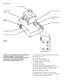
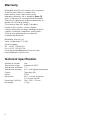
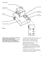
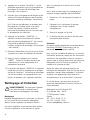
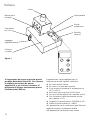
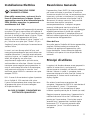
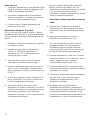
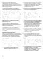
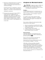
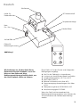
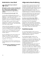
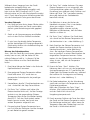
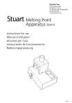
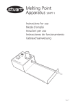
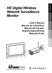
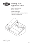
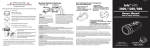
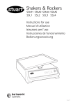
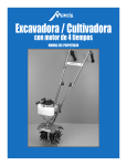
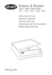
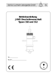
Melting Point
Apparatus SMP10
Instructions for use
Manuel d’utilisation
Istruzioni per l’uso
Instrucciones de funcionamiento
Bedienungsanweisung
STOP
SET
T
STAR
MAD
E IN
THE
UK
Scientific
Version 1.1
English
Eye viewer
Sample tube
holder
IEC connector
Temperature
display
Mains
on/off
Control panel
STOP
SET
T
STAR
MA
DE
IN TH
E UK
Extendible feet
Instruction facia
Figure 1
STOP
SET
START
MADE IN THE UK
Thank you for purchasing this Barloworld
Scientific product. To get the best
performance from the equipment, and for
your own safety, please read these
instructions carefully before use.
This equipment is designed to operate under the
following conditions:❖ For indoor use only
❖ Use in a well ventilated area
❖ Ambient temperature range
+5°C to +40°C
❖ Altitude to 2000m
❖ Relative humidity not exceeding 80%
❖ Mains supply fluctuation not exceeding 10%
❖ Overvoltage category II IEC60364-4-443
❖ Pollution degree 2 IEC664
If the equipment is not used in the manner
described in this manual the protection provided
by the equipment may be impaired.
Electrical Installation
THIS EQUIPMENT MUST BE EARTHED
Before connection please ensure that the
line supply corresponds to that stated on the
rating label. Power consumption is 70W.
There is an IEC socket at the rear of the right
hand side of the instrument for connection to the
mains supply, (see figure 1). The unit is supplied
with two mains leads fitted with IEC plugs for
connection to the instrument. One has a U.K. 3
pin plug and the other has a 2 pin “Shuko” plug
for connection to the mains supply. Choose the
lead appropriate for your electrical installation
and discard the other.
Should neither lead be suitable you should obtain
a moulded lead locally. If this is not possible, take
the lead with the U.K. plug and replace the plug
with a suitable alternative. See the enclosed
instruction sheet for advice on how to carry out
this procedure.
Should the mains lead require replacement a
cable of 1mm2 of harmonised code H05W-F
connected to an IEC 320 plug should be used.
N.B. The UK mains lead is protected by a 10A
fuse mounted in the plug top.
The mains lead should be connected to the
instrument BEFORE connection to the mains
supply.
IF IN DOUBT CONSULT A QUALIFIED
ELECTRICIAN
General Description
The Stuart SMP10 has been designed for
maximum safety and ease of use. The
temperature is selected, measured and displayed
digitally ensuring accuracy and avoiding the need
for a glass thermometer. Two samples can be
tested simultaneously. They are viewed via a
magnifying lens with clear observation aided by
built in illumination. Extendible feet allow the
unit to be operated at the optimum viewing
angle. Full access to the block allows easy
cleaning and maintenance.
Before Using your SMP10 for the first time
Once the unit is unpacked, select the appropriate
choice of self adhesive instruction label from the
multi-language set provided. Peel off the backing
and stick the label onto the left side of the
SMP10 facia. Apply the label carefully using a flat
object to smooth away air bubbles.
Principle of Operation
The SMP10 melting point apparatus has been
designed to give both quick and accurate results
as well as maximum convenience in use.
Melting point samples are placed in a glass
capillary tube which is placed in the aluminium
block inside the sample chamber. This block is
heated and the sample observed through the
magnifying lens until the melt occurs. The
melting point temperature may then be easily
read from the large LED display.
In order to avoid the necessity to continually
watch the sample the SMP10 is equipped with a
“plateau” function. This allows a temperature to
be set a few degrees below the expected melting
point. The SMP10 will then heat to this
temperature very rapidly (20°C per minute) and
hold it until the operator is ready to begin
measuring. It can safely be left to do this
unattended.
1
Once measuring is started the SMP10 will heat
slowly (2°C per minute) from the plateau
temperature until the melt occurs. This slow rate
of heating allows very accurate melting points to
be obtained.
Before Use
Place the unit on a firm, level surface and extend
the feet at the rear of the instrument so that the
unit is at a convenient viewing angle.
6.
Release the set button. The new plateau
temperature is now set and all function
lights will go out (The plateau setting can be
checked at any time during operation by
pressing and holding the set button). This
action will not interfere with the operation
of the unit).
7.
Insert the tube into the side of the heating
block via the holes provided. For
convenience this can be done from either
side of the block. Look down the magnifier
and position the tube so that the sample
can be observed clearly.
Caution: The heating block may be HOT.
8.
Press the start key. The unit will quickly heat
up to the plateau temperature (the heating
light will be illuminated - see figure 1)
9.
Once the plateau temperature has been
reached the plateau light will be illuminated
as well as the heating light - see figure 1.
N.B. At low plateau temperatures there may
be some overshoot. Wait until the plateau
light comes on before proceeding in order to
ensure that the temperature has stabilised.
Connect to the mains electricity supply and
switch on by means of the mains on/off switch.
The actual block temperature will now be shown
on the three digit LED display and the
illumination in the sample chamber will come on.
Measuring a Melting Point
N.B. If the unit has been used recently the block
may be too hot for your sample. If this is the case
press the stop button and allow the unit to cool
before proceeding.
1.
Prepare sample by placing a small amount in
the end of a glass capillary tube.
2.
Decide on a suitable plateau temperature.
This should be approximately 10°C below
the expected melting point of the sample.
3.
Check that all 3 function lights are
extinguished. If not, press the stop button.
4.
Press and hold the set button (the plateau
light will flash). The display will now show
the current plateau temperature. When first
switched on this will be 50°C but note that
if the unit has recently been used the value
may have been re-set by the previous user.
5.
2
The desired plateau temperature may now
be set using the arrow keys to scroll the
display up or down as required.
10. Press the start button again. The block will
begin to heat at the pre-set ramp rate of
2°C per minute (The plateau light will go
out and the ramping and heating lights will
both be illuminated - see figure 1.)
11. Observe the sample until the melt occurs
and record the temperature from the digital
display.
12. After the melt has occurred press the stop
button. All function lights will go out and
the unit will cool to ambient temperature.
13. Pressing the start button again will cause the
unit to return to the plateau temperature
instead of ambient. The heating light will
come on even if the temperature is above
the plateau and the unit is, in fact, cooling.
Cleaning & Servicing
WARNING: Ensure the unit is
disconnected from the mains electricity
supply and allowed to cool before
attempting any cleaning or servicing.
Cleaning
Periodically clean the instrument using a damp
cloth and mild detergent solution. Do not use
harsh or abrasive cleaning agents.
Broken melting point tubes may be removed
from the block simply by pushing them through
with a piece of wire or similar tool.
For access to the block for more thorough
cleaning the sample chamber cover must be
removed.
1. Remove the 3 retaining screws and lift off the
cover.
2. Loosen the screw retaining the metal plate
but do not remove completely.
3. Push the plate to one side.
3) Two fuses are mounted on the rear of the IEC
connector (both ‘Live’ and ‘Neutral’ mains
supply leads are fused). These fuses can be
removed and replaced by hand. ALWAYS
replace the fuse by ones of the correct values
shown below:
For 230V, 50Hz - T1A
For 120V, 60Hz - T1.6A
4) Refit the base and four securing screws.
5) It is advisable to perform a ‘PAT’ (Portable
Appliance Test) electrical safety test, or
equivalent, before the SMP10 is put back into
operation.
For a comprehensive list of parts and a Service
Manual required by service engineers conducting
internal repairs, please contact the Technical
Service Department of Barloworld Scientific Ltd.
quoting both the model and serial number.
Only spare parts supplied or specified by
Barloworld Scientific Ltd. or its agents should be
used. Fitting of non-approved parts may affect
the performance and safety features designed
into the instrument.
4. The glass window in the top of the block may
now be removed.
If in any doubt, please contact the Technical
Service Department of Barloworld Scientific Ltd.
or the point of sale.
Servicing
Any repairs or replacement of parts MUST only
be undertaken by suitably qualified personnel.
Barloworld Scientific Ltd.
Stone, Staffordshire ST15 0SA
United Kingdom
Tel: +44 (0) 1785 812121
Fax: +44 (0) 1785 813748
e-mail [email protected]
www.barloworld-scientific.com
There are two replaceable fuses on the rear of
the IEC mains connector. The cause of any fuse
failure should be investigated and corrected.
Proceed as follows:
1) Ensure the SMP10 is disconnected from the
mains supply.
2) Unscrew the four screws on the base of the
unit and remove the base plate. Do not
disconnect or pull on the base earth bonding
wire.
3
Warranty
Barloworld Scientific Ltd. warrants this instrument
to be free from defects in material and
workmanship, when used under normal
laboratory conditions, for a period of three (3)
years. In the event of a justified claim Barloworld
Scientific will replace any defective component or
replace the unit free of charge.
This warranty does NOT apply if damage is
caused by fire, accident, misuse, neglect,
incorrect adjustment or repair, damage caused by
incorrect installation, adaptation, modification,
fitting of non-approved parts or repair by
unauthorised personnel.
Barloworld Scientific Ltd.
Stone, Staffordshire ST15 0SA
United Kingdom
Tel: +44 (0) 1785 812121
Fax: +44 (0) 1785 813748
e-mail [email protected]
www.barloworld-scientific.com
Technical Specification
Number of samples
Temperature range
Temperature resolution
Temperature accuracy
Display
Sensor
Ramp rates
Dimensions (WxDxH)
Net weight
4
Two
Ambient to 300°C
1°C
±1°C of displayed temperature
Three digit LED
PT100
20°C / minute to plateau
2°C /minute to melt
160 x 220 x 170 mm
1.8 Kg
Français
Loupe d’observation
Enbase cee
Support tube
echantillon
Affichabe
temperature
Narche /
Arret
Panneau
de controle
STOP
SET
T
STAR
MA
DE
IN TH
E UK
Pieds anovibles
Nobe operatoire
Figure 1
STOP
SET
START
MADE IN THE UK
Merci d’acheter ce produit de Barloworld
Scientific. Pour obtenir le bon
fonctionnement de l’équipement, et pour
votre sécurité, lire avec attention les
instructions ci-dessous avant l’utilisation.
Le matériel Barloworld Scientific est conçu pour
fonctionner dans les conditions suivantes.
❖ Pour l’usage en intérieur seulement
❖ Utilisation dans une pièce bien aérée
❖ Température ambiante +5°C à +40°C
❖ Altitude inférieure à 2000m
❖ Humidité relative n’excédant pas 80%
❖ Fluctuations de l’alimentation électrique
n’excédant pas 10% de la valeur nominale
❖ Catégorie II IEC60364-4-443 de surtension
❖ Degré 2 IEC664 de pollution
Si l’équipement n’est pas utilisé de la façon
décrite dans ce manuel les différentes fonctions
de l’appareil peuvent être altérées.
5
Installation Électrique
CET ÉQUIPEMENT DOIT ÊTRE RELIE À
LA TERRE
Avant le raccordement, s’assurer que
l’alimentation électrique convient. Cet
appareil exige une alimentation 230V, 5060Hz, monophasé. La puissance est de 70W.
Une embase CEE est située à l’arrière du côté
droit de l’instrument pour le raccordement à
l’alimentation électrique, (voir le schéma 1).
L’instrument est fourni avec deux câbles secteur
équipés d’une prises CEE pour le raccordement à
l’instrument. Sur un, se trouve une prise aux
normes anglaises et sur l’autre une prise de
européen 2P+T. Choisir le câble approprié pour
votre installation électrique et jeter l’autre.
Si ni l’un ni l’autre ne conviennent, vous devrez
alors obtenir le bon câble localement. Si ce n’est
pas possible, prendre celui avec la prise anglaise,
la couper et la remplacer par celle
correspondante au pays d’utilisation. Voir la
feuille d’instruction incluse pour le montage de
cette prise.
Si l’état du câble secteur exige son remplacement
un câble de 1mm2 norme H05W-F relié à une
prise CEE 320 devra être employé.
N.B. Le câble anglais est protégé par un fusible
10A monté dans la prise.
Le câble doit être relié à l’instrument AVANT le
raccordement à l’alimentation électrique.
EN CAS DE DOUTE CONSULTER UN
ÉLECTRICIEN QUALIFIÉ
6
Description Générale
Le Stuart SMP10 a été conçu pour une sécurité et
facilité d’utilisation maximale. L’affichage digital
donne la température choisie et mesurée avec
exactitude et évitant ainsi l’utilisation d’un
thermomètre à mercure en verre. Deux
échantillons peuvent être examinés
simultanément. ls sont observés par
l’intermédiaire d’une loupe ayant une luminosité
exceptionnelle. Les pieds de réglage de l’appareil
permettent à l’appareil d’être positionné pour un
confort d’utilisation optimum. Le plein accès au
bloc permet le nettoyage et l’entretien aisé.
Avant d’utiliser votre SMP10 pour la
première fois :
Une fois que l’unité est déballée, choisir
l’étiquette d’instructions, adhésive, appropriée à
la langue du pays d’utilisation. Coller l’étiquette
sur le côté gauche de la face avant du SMP10.
Appliquer l’étiquette en employant un objet plat
pour lisser les bulles d’air.
Principe de
Fonctionnement
L’appareil à point de fusion SMP10 a été conçu
pour donner des résultats rapides et précis.
Les échantillons sont placés dans un tube
capillaire en verre, scellé à une extrémité, dans le
bloc d’aluminium à l’intérieur de la chambre de
mesure. Ce bloc est chauffé et l’échantillon est
observé par l’objectif jusqu’à ce que le
changement d’état se produise. La température
du point de fusion peut alors être facilement
relevée sur le grand affichage digital.
Afin d’éviter l’observation continuelle de
l’échantillon, le SMP10 est équipé d’une fonction
“plateau”. Ceci permet de sélectionner une
température placée quelques degrés au-dessous
du point de fusion prévu. Le SMP10 chauffera
alors jusqu’à cette température très rapidement
(20C° par minute) et la maintiendra jusqu’à ce
que l’opérateur soit prêt à observer. Durant cette
montée en température, l’appareil ne nécessite
pas de surveillance particulière.
Une fois la mesure commencée, le SMP10
chauffera lentement (2C° par minute), de la
température de plateau jusqu’à ce que la fusion
se produise. Cette montée lente permet une
détermination précise des points de fusion.
Avant l’emploi
1. Placer l’unité sur une surface à niveau et
placer les pieds à l’arrière de l’instrument de
sorte que l’unité soit dans une position
optimale pour l’observation.
2. Relier à l’alimentation électrique et mettre en
fonctionnement à l’aide de I’interrupteur
“Marche/Arrêt”.
3. La température réelle de la chambre de
mesure sera affichée et la chambre de mesure
sera illuminée.
4. Votre SMP10 est maintenant opérationnel.
Détermination d’un point de fusion
N.B. Si l’appareil a été utilisé récemment le bloc
peut être trop chaud pour votre échantillon. Si
c’est le cas, appuyer sur la touche “ARRÊT” et
laisser l’unité refroidir avant la mise en route de la
procédure suivante.
1. Préparer l’échantillon en plaçant un peu de ce
dernier dans l’extrémité d’un tube capillaire
en verre
2. Choisir la température appropriée pour le
plateau. Celle-ci devra être
approximativement 10C° au-dessous du point
de fusion prévu.
3. Vérifier que les 3 témoins de fonctionnement
sont éteints. Sinon, appuyer sur la touche
“ARRÊT”.
4. Appuyer et maintenir le bouton de sélection
(la lumière de plateau clignotera). L’affichage
donnera alors la température courante de
plateau. Lors de la première utilisation celle-ci
sera de 50C°. Celle-ci aura pu être remise à
zéro par l’utilisateur précédent.
5. La température désirée de plateau peut
maintenant être sélectionnée en utilisant les
touches de déplacement haut ou bas pour
obtenir celle exigée.
6. Relâcher le bouton, la nouvelle température
de plateau est maintenant affichée et toutes
les lumières de fonction s’éteindront (le
plateau peut être vérifié à tout moment lors
du fonctionnement en appuyant et
maintenant le bouton de sélection. Cette
action n’interférera dans le bon
fonctionnement de l’appareil).
7. Insérer le tube par le côté du bloc de
chauffage dans les orifices prévus à cet effet.
Ceci peut être fait de l’un ou l’autre côté du
bloc. Placer le tube de sorte qu’on puisse
observer clairement l’échantillon.
Attention: Le bloc de chauffage peut
être CHAUD
7
8. Appuyer sur la touche “MARCHE”. L’unité
chauffera rapidement jusqu’à la température
de plateau (la lumière de chauffage sera
illuminée - voir schéma 1).
9. Une fois que la température de plateau a été
atteinte la lumière de plateau sera illuminée
comme la lumière de chauffage - voir schéma 1.
N.B. À basses températures, le plateau peut
être dépassé. Attendre jusqu’à ce que la
lumière de plateau s’illumine avant de
continuer la procédure afin de s’assurer que
la température est stabilisée.
10. Appuyer sur le bouton “MARCHE” à
nouveau. Le bloc commencera à chauffer
avec une pente préréglée de 2C° par minute
(la lumière de plateau s’éteindra et les
lumières de pente de chauffage s’illumineront
- voir schéma).
11. Observer l’échantillon jusqu’à ce que la fusion
se produise et noter la température affichée.
avec un morceau de fil de fer ou d’un outil
semblable.
Pour l’accès au bloc pour un nettoyage plus
complet le capot supérieur doit être enlevé.
1. Enlever les 3 vis de retenue et enlever le
capot.
2. Desserrer la vis maintenant la plaque
métallique mais ne pas l’enlever
complètement.
3. Pousser la plaque sur le côté.
4. La fenêtre de verre au-dessus du bloc peut
maintenant être enlevée.
Entretien
N’importe quelles réparations ou remplacement
des pièces DOIVENT être entrepris par du
personnel convenablement qualifié.
12. Après la fusion, appuyer sur la touche
“ARRÊT”. Toutes les lumières de fonction
s’éteindront et l’unité redescendra à la
température ambiante.
Pour une liste complète de pièces et un manuel
d’entretien technique, requis par des techniciens
conduisant des réparations internes, entrer en
contact avec le service après vente technique de
Barloworld Scientific France en précisant le
modèle et le numéro de série.
13. La pression du bouton “MARCHE” à nouveau
ramènera l’unité à la température de plateau
au lieu de l’ambiant. La lumière de chauffage
s’illuminera même si la température est audessus du plateau, mais l’appareil refroidira.
Seules les pièces de rechange fournies ou
indiquées par Barloworld Scientific France ou ses
revendeurs doivent être employées. L’utilisation
de pièces non-approuvées peut affecter le
fonctionnement et la sécurité de l’instrument.
Nettoyage et Entretien
En cas de doute, contacter avec le service
technique de Barloworld Scientific France ou
votre revendeur.
AVERTISSEMENT: S’assurer que l’appareil
n’est plus alimenté et refroidit avant
d’entamer le nettoyage ou l’entretien.
Nettoyage
Nettoyer périodiquement l’instrument en utilisant
un tissu humide et une solution détergente
douce. Ne pas employer de produits abrasifs.
Des tubes capillaires cassés peuvent être enlevés
du bloc simplement en les poussant à travers
8
Barloworld Scientific France SAS
ZI du Rocher Vert - BP 79
77793 Nemours Cedex
France
Tél: +33 1 64 45 13 13
Fax: +33 1 64 45 13 00
e-mail: [email protected]
Garantie
Barloworld Scientific France garantit cet appareil
de tout défaut de fabrication ou de montage
pour une utilisation normale en laboratoire et ce
durant trois (3) ans. En cas de défaillance,
Barloworld Scientific France s’engage à remplacer
gratuitement la pièce défectueuse ou l’appareil si
ce dernier était déclaré irréparable.
Cette garantie ne s’applique pas si les dommages
sont dus à un incendie, un accident, une
inondation, une négligence ou une utilisation
inadéquate. La garantie ne s’applique pas non
plus si l’appareil n’a pas été installé correctement,
réparé par une personne non qualifiée ou modifié
à l’aide de pièces détachées ne provenant pas de
la société Barloworld Scientific France.
Cette garantie ne modifie pas les statuts et droits
des échanges commerciaux.
Barloworld Scientific France SAS
ZI du Rocher Vert - BP 79
77793 Nemours Cedex
France
Tél: +33 1 64 45 13 13
Fax: +33 1 64 45 13 00
e-mail: [email protected]
9
Italiano
Visore
Blocco porta
campioni
Alimentazione
Display
temperatura
Interruttore
on / off
Pannello
comandi
STOP
SET
Appoggio
regolabile
T
STAR
MA
DE
IN TH
E UK
Etichetta
istruzioni
Figure 1
STOP
SET
START
MADE IN THE UK
Vi ringraziamo per avere acquistato questo
prodotto Barloworld Scientific. Per ottenere
la migliore prestazione da questo
apparecchio, e per la Vostra sicurezza, Vi
preghiamo di leggere attentamente queste
istruzioni prima dell’uso.
L’apparecchio è stato progettato per un
funzionamento nelle seguenti condizioni:
❖ Da usarsi solo all’interno
❖ Da usarsi in un’area ben ventilata
❖ In un campo di variazione di temperatura da
+5°C a +40°C
❖ Ad un’altitudine massima di 2000 metri
❖ Con una umidità relativa non superiore a 80%
❖ Con fluttuazioni dell’alimentazione da rete
non superiori a 10%
❖ Categoria di sovratensione II CEI60364-4-443
❖ Grado di contaminazione 2 CEI664
Se l’apparecchio non è usato come specificato nel
presente manuale, la protezione offerta
dall’apparecchio stesso può essere ridotta.
10
Installazione Elettrica
L’APPARECCHIO DEVE ESSERE
COLLEGATO A TERRA.
Prima della connessione, assicurarsi che la
linea di alimentazione sia idonea. Questo
apparecchio necessita di un’alimentazione da
230V, 50-60Hz, monofase. La potenza di
assorbimento è di 70W.
Sulla parte posteriore dell’apparecchio è presente
una presa CEI per la connessione all’impianto di
alimentazione (fig.1). Ogni unità viene fornita con
due cavi di alimentazione dotati di spina CEI per
la connessione dell’apparecchio alla linea
elettrica. Un cavo è dotato di spina “Inglese” a 3
pin, l’altro ha una spina tipo “Shuko” a 2 pin.
Scegliere il cavo più adatto per la connessione e
scartare l’altro.
In caso i cavi non fossero adatti all’uso, sarà
necessario provvedere alla loro sostituzione con
modello alternativo. E’ possibile eventualmente
sostituire la spina, se i modelli forniti non fossero
adatti alle esigenze, con altro tipo,
semplicemente tagliando la spina esistente,
sostituendola con altro tipo. Ulteriori istruzioni
mostrano come eseguire questa procedura. In
caso di sostituzione del cavo di alimentazione,
sarà necessario utilizzare un cavo da 1mm2
codificato come H05W-F e connesso con spina
europea CEI320.
N.B.: Il cavo di alimentazione inglese è protetto
da un fusibile di 10A montato sulla spina.
Il cavo di alimentazione deve essere connesso
all’apparecchio prima di essere collegato
all’impianto elettrico.
IN CASO DI DUBBIO, CONSULTARE UN
ELETTRICISTA QUALIFICATO.
Descrizione Generale
L’apparecchio Stuart SMP10 è stato progettato
per essere utilizzato in condizioni di massima
sicurezza e semplicità d’uso. La temperatura viene
impostata, misurata e visualizzata in via digitale,
garantendo l’accuratezza ed evitando l’uso di
termometri di vetro a mercurio. Sarà possibile
esaminare due capillari campione
contemporaneamente. I campioni vengono
osservati nitidamente tramite una lente di
ingrandimento illuminata, e i piedini di appoggio
regolabili permettono la scelta del migliore
angolo di osservazione. Il completo accesso al
blocco riscaldante permette una facile pulizia e
mantenimento dell’apparecchio.
Prima dell’uso
Una volta aperto l’imballo del Vostro apparecchio,
scegliete l’etichetta adesiva contenente le
istruzioni da applicare all’apparecchio, nella
lingua desiderata. Successivamente applicate
l’etichetta sulla parte sinistra del pannello dei
comandi.
Principi di utilizzo
I campioni da fondere devono essere preparati in
capillari di vetro chiusi a un’estremità,
successivamente introdotti nel blocco riscaldante.
Mentre il blocco si scalda, il campione viene
osservato attraverso la lente fino alla fusione. La
temperatura di fusione verrà visualizzata sul
display digitale.
Per evitare la continua osservazione del
campione, l’apparecchio SMP10 è stato dotato di
una funzione di “picco”. Ciò permette
l’impostazione di una temperatura di poco
inferiore a quella prevista per la fusione (se nota).
Raggiunta questa temperatura, l’apparecchio la
manterrà costante fino a che l’utilizzatore sia
pronto per l’osservazione. Cominciata questa
seconda fase, l’apparecchio riscalderà molto
lentamente (2°C al minuto) partendo dalla
temperatura “picco” fino alla fusione del
campione.
11
Prima dell’uso
1. Sistemare l’apparecchio su una superficie piana
rigida ed estendere i piedi di appoggio fino al
livello di angolazione desiderato.
2. Connettere l’apparecchio all’alimentazione
elettrica e metterlo in funzione con l’apposito
pulsante di accensione/spegnimento.
3. Il display mostra l’attuale temperatura del
blocco, ora illuminato.
Misurazione del punto di fusione
N.B. Se l’unità è stata usata di recente, il blocco
potrebbe essere già caldo. In questo caso premere
il pulsante Stop e attendere il raffreddamento del
blocco.
1. Preparare il campione introducendo la polvere
nel capillare di vetro.
2. Decidere se impostare una temperatura
“picco”. E’ sufficiente impostare una
temperatura di 10°C inferiore al punto di
fusione previsto (se noto).
3. Verificare che le spie luminose di funzione
siano spente, altrimenti premere Stop.
4. Premere e mantenere premuto il tasto Set (la
spia di “picco” lampeggia). Il display mostra
ora la temperatura di picco (la prima volta sarà
di 50°C).
7. Inserire il capillare dalla parte laterale del
blocco, attraverso gli appositi fori. Per
convenienza ciò può essere fatto da entrambi
i lati. Osservare attraverso la lente e
posizionare il capillare (delicatamente) fino ad
avere la migliore osservazione.
Attenzione: il blocco potrebbe essere già
caldo!
8. Premere Start. L’apparecchio riscalderà
velocemente fino alla temperatura di picco
impostata (la spia di riscaldamento è accesa fig.1).
9. Raggiunta la temperatura di picco, si
accenderà una seconda spia - fig.1.
N.B.: Se la temperatura di picco è bassa,
potrebbe verificarsi una fluttuazione di
temperatura, perciò è meglio attendere
l’accensione della spia di picco, che assicura
la stabilità della temperatura impostata.
10. Premere nuovamente il tasto Start. Il blocco
viene ora scaldato a 2°C al minuto (la spia di
picco si spegne, le spie di rampa e
riscaldamento restano accese - fig.1.
11. Osservare attentamente il campione fino al
momento della fusione e registrare la relativa
temperatura sul display.
5. Si può ora impostare la nuova temperatura di
picco, utilizzando i tasti freccia in aumento o
in diminuzione rispetto al display.
12. Conclusa la fusione della sostanza campione,
premere Stop. Tutte le spie luminose si
spengono e l’apparecchio torna alla
temperatura ambiente.
6. Rilasciare il pulsante Set: ora la nuova
temperatura di picco è visualizzata, e le spie di
funzione sono spente (la temperatura di picco
può essere controllata in ogni momento,
premendo il tasto Set. Ciò non interferisce nel
riscaldamento del blocco).
13. Premendo Start prima dell’effettivo
raffreddamento del blocco, l’apparecchio
tornerà automaticamente alla temperatura di
picco precedentemente impostata. La spia
luminosa di riscaldamento si accenderà pur se
l’apparecchio è in fase di raffreddamento.
12
Pulizia e manutenzione
ATTENZIONE: Assicurarsi che l’apparecchio
sia scollegato all’impianto di alimentazione
elettrico e che il blocco sia sufficientemente
raffreddato prima di procedere a qualsiasi
operazione di pulizia o manutenzione.
Pulizia: pulire periodicamente l’apparecchio
usando un panno morbido e una soluzione
detergente leggera. Non utilizzare agenti
detergenti aggressivi o corrosivi. I capillari
eventualmente rotti all’interno del blocco
possono essere facilmente eliminati spingendoli
con un filo rigido od oggetti similari. Per il
completo accesso al blocco riscaldante è
necessario rimuovere il coperchio protettivo:
1. Rimuovere le 3 viti di sicurezza e sollevare il
coperchio.
2. Svitare la vite che assicura il piatto di metallo
senza rimuoverla completamente.
3. Spingere il piatto di metallo da una parte.
4. Ora si può rimuovere la protezione in
policarbonato sopra il blocco.
Manutenzione: Ogni riparazione o sostituzione
di parti di ricambio DEVE necessariamente essere
effettuata da personale altamente qualificato.
In caso di dubbio, contattare la Barloworld
Scientific Italia Srl, Via Alcide de Gasperi 56
20077 Riozzo di Cerro al Lambro, Milano, Italia
Tel. 02/98230679 Fax 02/98230211.
Garanzia
La Barloworld Scientific Ltd. garantisce questo
apparecchio come esente da difetti nei materiali e
in fase di fabbricazione, se usato alle normali
condizioni di laboratorio, per un periodo tris (3)
anni. In caso di reclamo giustificato, la Barloworld
Scientific sostituirà ogni componente difettoso o
l’intero apparecchio, senza onere alcuno. Tale
garanzia NON verrà applicata in caso di danni
causati da incendi, incidenti, uso non corretto,
negligenza, riparazione non autorizzata,
installazione non corretta, adattamenti non
autorizzati, modifiche non autorizzate,
montaggio di parti non originali o eseguite da
personale non autorizzato.
Barloworld Scientific Italia Srl
Via Alcide de Gasperi 56
20077 Riozzo di Cerro al Lambro
Milano Italia
Tel: +39 (0)2 98230679
Fax: +39 (0)2 98230211
e-mail: [email protected]
www.barloworld-scientific.it
Le seguenti parti di ricambio sono disponibili
presso il Vostro fornitore:
Lampada per illuminazione del blocco.
Set di etichette per istruzioni multilingue.
Confezione da 2 piedi di appoggio regolabili.
ESMP102(S)
FSMP1010
USMP10
Per una lista più completa di ricambi o manuale
di servizio, contattare il Centro Tecnico della
Barloworld Scientific Ltd. più vicino, specificando
modello e numero di serie. Sono autorizzate le
operazioni di sostituzione eseguite con parti di
ricambio originali Barloworld Scientific. L’utilizzo
di parti non originali può compromettere la
funzionalità dell’apparecchio e rendere vane le
misure di sicurezza esistenti sull’apparecchio.
13
Espanol
˜
Visore
Ouficios para
muestras
Conectar de
corriente IEC
Indicadar
de temperatura
Boton
Paro / Marcha
Pauel
de contral
STOP
SET
T
STAR
MA
DE
IN TH
E UK
Patas plegables
Caratula frontal
Figure 1
STOP
SET
START
MADE IN THE UK
Gracias por haber adquirido un producto
Barloworld Scientific. Para obtener las
máximas prestaciones del equipo, y para su
seguridad, por favor, lea detenidamente
estas instrucciones de funcionamiento antes
de usar el aparato.
Este aparato ha sido diseñado para ser utilizado
bajo las siguientes condiciones:
❖ Para usar en locales al abrigo de la intemperie
❖ Para usar en locales bien ventilados
❖ Condiciones de trabajo: temperatura
ambiente +5ºC a +40ºC
❖ Altitud hasta 2.000m
❖ La humedad relativa no excederá de 80%
❖ Las fluctuaciones de la corriente no excederán
un 10% del valor nominal
❖ Sobre-Voltaje categoría II IEC60364-4-443
❖ Grado de contaminación 2 IEC664
Si el equipo no se usa de la manera descrita en
este manual, la protección proporcionada por el
aparato puede no ser adecuada.
14
Instalación eléctrica
ESTE EQUIPO DEBER SER CONECTADO
A UNA TOMA DE TIERRA.
Antes de conectar el aparato por favor
asegurarse de que la toma de corriente es
utilizable. El aparato requiere una corriente
de 230V, 50Hz, monofásica. Potencia
consumida 75W.
Hay un conector IEC en la parte trasera del
instrumento para enchufar a la corriente (ver
figura 2). La unidad se suministra con dos cables
con conexión IEC para acoplar al instrumento.
Uno es con clavija UK con tres bornes y el otro es
tipo “Shuko” con dos bornes y toma de tierra
utilizable en el resto de Europa. Escoger el cable
adecuado para su instalación eléctrica y descartar
el otro.
Si ninguno de los conectores es adecuado para su
instalación eléctrica, desmonte el enchufe con
conector UK y coloque el adecuado. Ver las
instrucciones adjuntas de cómo proceder a este
cambio.
Si se requiere cambiar el cable, debe colocarse
uno con sección de 1mm2, con código de
aislamiento H05W-F, y conector IEC 320 en uno
de sus extremos para la conexión a la unidad.
SI TIENE CUALQUIER DUDA, CONSULTE A UN
ELECTRICISTA CUALIFICADO
El cable debe ser insertado al instrumento ANTES
de su conexión a la corriente.
Descripción General
El SMP10 ha sido diseñado para la máxima
seguridad y facilidad de uso. La temperatura se
selecciona, mide y visualiza digitalmente,
asegurando la exactitud y sin necesidad de
utilizar un termómetro de vidrio. Pueden medirse
hasta dos muestras simultáneamente. La
observación se realiza por medio de una lente
muy nítida ayudado por un sistema de
iluminación; además unos pies regulables
permiten un óptimo ángulo de observación; todo
ello situado en un bloque de fácil acceso para su
limpieza y mantenimiento.
Antes de usar por primera vez su SMP10
Una vez desempaquetado el aparato, seleccionar
la etiqueta donde van impresas las instrucciones,
dependiendo del idioma que se use: Español,
Inglés, Italiano o Francés, y pegarlo en la parte
izquierda del panel de control del SMP10,
aplanándolo bien para evitar que queden
burbujas debajo de la etiqueta.
Principio del
funcionamiento
El Punto de fusión SMP10 ha diseñado para
poder obtener unos resultados precisos y rápidos
a la vez que, con gran facilidad en su uso.
Las muestras para la determinación del punto de
fusión se colocan en un tubo capilar, cerrado por
uno de sus extremos, el cual se coloca en uno de
los orificios del bloque de aluminio de la cámara.
Este bloque es calentado y la evolución de la
muestra observada a través del visor con lupa,
hasta el punto de fusión de la misma. La
temperatura del punto de fusión puede
observarse fácilmente en el indicador digital.
Para evitar una larga espera en la determinación
del punto de fusión, el SMP10 se ha equipado
con la función “meseta”. Esto permite fijar una
temperatura de inicio unos pocos grados por
debajo del valor esperado. El SMP10 alcanzará
rápidamente dicha temperatura (20ºC/min) y
15
permanecerá estable manteniendo
indefinidamente y con toda seguridad, la
temperatura de “meseta”, en espera de que el
operador quiera comenzar a determinar el punto
de fusión de la muestra.
4. Presionar y mantener el botón SET (la luz de
la función “meseta” destellará); el display
indicará ahora el último valor programado de
temperatura de meseta, (por defecto la
primera vez indica 50ºC).
Una vez que la medición ha comenzado, el
SMP10 calentará con una rampa de temperatura
fija de 2ºC/min, desde la temperatura de la
“meseta” hasta que se observe la fusión de la
muestra. Esta pendiente de sólo 2ºC/min,
consigue que el valor medido de punto de fusión
sea muy preciso.
5. Introducir el valor que se desee por pulsación
de las teclas de subida o bajada.
Antes de Usar
Colocar la unidad en un sitio firme y nivelado,
extender los pies, que están plegados en la parte
trasera, para dejar el aparato en un ángulo
conveniente de visión.
Enchufar el cable a la corriente eléctrica, y
posteriormente poner en marcha el aparato por
medio del interruptor on/off.
La temperatura a la que esté el bloque de
aluminio será mostrada en el display con tres
dígitos, y la cámara se iluminara por medio de
una lámpara.
Medición del Punto de Fusión.
Nota. Si la unidad acaba de ser usada, el bloque
de aluminio de la cámara, puede estar demasiado
caliente para su muestra, debe en este caso,
pulsar el botón STOP y esperar a que se enfríe,
antes de proceder.
1. Introducir una pequeña cantidad de muestra
en el final de un tubo capilar.
2. Escoger la temperatura de “meseta”. Ésta
debe estar unos 10ºC por debajo de la
temperatura de punto de fusión esperada.
3. Las tres luces de función deben estén
apagadas, si no, pulsar la tecla STOP.
16
6. Dejar de presionar el botón SET. El nuevo
valor de “meseta” está ahora memorizado, y
la luz apagada (éste valor puede ser
comprobado en cualquier momento,
simplemente pulsando y soltando la tecla
SET). Esta acción no interfiere en nada el
normal funcionamiento del aparato.
7. Insertar el capilar con la muestra en el bloque
de calefacción, mirando simultáneamente por
el visor, para centrar el capilar. El capilar
puede entrarse tanto desde el lado izquierdo
como el derecho del bloque de aluminio.
Puede enfocarse para una visión óptima
ajustando la altura del ocular del visor.
8. Pulsar la tecla START. La unidad se calentará
rápidamente hasta llegar a la temperatura de
“meseta”. (La luz de calentamiento se
iluminará, ver fig 1.)
9. Una vez que la temperatura de “meseta”
haya sido alcanzada, la luz de “meseta” se
iluminará, además de la luz de calentamiento
– ver fig 1.
NOTA: Un valor muy bajo en temperatura de
“meseta” puede producir que se sobrepase
temporalmente el valor programado, Esperar
hasta que la luz de “meseta” esté iluminada
para proceder, y así asegurarse que la
temperatura permanezca estable.
10. Pulsar nuevamente la tecla START, el bloque
comenzará a calentar a partir de la
temperatura de meseta a razón de 2ºC/min
(La luz de “meseta” se apagará y las de
calentamiento y rampa se iluminarán).
11. Observar el comportamiento de la muestra a
través del visor, hasta ver que se funde.
Anotar la temperatura que muestra en ese
momento el display.
Después de anotar la temperatura, pulsar la
tecla ”STOP” y todas las luces de función se
apagarán y la unidad se irá enfriando hasta
temperatura ambiente.
12. Presionando nuevamente la tecla START, la
unidad vuelve a la programación de
temperatura de “meseta” en lugar de la
temperatura ambiente quedando la luz de
calentamiento encendida, por si se quiere
volver a repetir la determinación, o bien se
puede volver al punto 4, para programar un
nuevo valor.
Limpieza & Mantenimiento
ATENCION: Asegurarse que la unidad está
desconectada de la electricidad y se ha
enfriado, antes de realizar cualquier acción
de limpieza o mantenimiento.
Limpieza
Limpiar periódicamente el instrumento con una
gamuza suave utilizando una solución jabonosa
neutra. No deben usarse estropajos o agentes
abrasivos para limpiar.
Los capilares que se hayan podido romper,
pueden ser extraídos del bloque, simplemente
haciendo pasar otro capilar o un alambre fino
transversalmente.
Para acceder al bloque de calentamiento debe
desmontarse la tapa superior.
1. Quitar los protectores de tornillos de la tapa
2. Aflojar el tornillo que sujeta la placa metálica,
sin quitarla del todo 1.
3. Colocar la placa hacia un lado
4. La ventanilla de cristal en el fondo del
bloque, puede ahora ser extraída.
Mantenimiento
Cualquier reparación o reemplazamiento de
piezas de recambio DEBE sólo ser realizada por
personal qualificado.
Para una lista más exhaustiva de piezas de
recambio, por favor contactar con el
Departamento Técnico de Barloworld Scientific
Ltd, indicando el modelo y nº de serie.
Sólo deben utilizarse recambios originales
suministrados por Barloworld Scientific o sus
agentes autorizados. La colocación de recambios
no originales, puede afectar a las prestaciones y
características de seguridad del instrumento.
Si tiene cualquier duda, o para recibir el manual
técnico, por favor contactar con el Departamento
Técnico de Afora S.A.
17
Garantía
Barloworld Scientific Ltd, garantiza que este
instrumento está libre de defectos en los
materiales y fabricación, siempre que el aparato
se use en condiciones normales de laboratorio,
por un periodo de tres (3) años. Si aparece no
obstante cualquier defecto justificado, Barloworld
Scientific reemplazará el componente defectuoso
sin cargo.
Esta garantía NO es aplicable sí el daño es
causado por fuego, accidente, mal uso,
negligencia, ajuste o reparación incorrecta, rotura
por instalación incorrecta, adaptación o
modificación, colocación de recambios no
originales, o reparación por personal no
autorizado.
Afora S.A.
Calle Aribau 240
08006 Barcelona
Spain
Tel: +343 93-306 98 00
Fax: +343 93-306 98 23
e-mail: [email protected]
www.afora.com
Especificaciones técnicas
Número de muestras
Rango de temperatura
Resolución
Exactitud
Display
Sensor
Rampas
Dimensiones (AnxAlxFo)
Peso Neto
18
Dos
Ambiente a 300°C
1°C
±1%
Tres dígitos
PT100
20°C / minuto para temperatura de “meseta”
2°C /minuto para punto de fusión
160 x 170 x 220 mm
1,8 Kg Requerimientos
Deutsch
Sichtfenster
Halter für
Probenröhrchen
IEC Netzanschluß
Temperaturanzeige
Netz
Ein / Aus
Bedienfläche
STOP
SET
T
STAR
MA
DE
IN TH
E UK
Aufstellfüße
Fläche für
Bedienungshinweise
Abbildung 1
STOP
SET
START
MADE IN THE UK
Wir bedanken uns für den Kauf dieses
Barloworld Scientific Produkts. Lesen Sie
bitte vor dem Gebrauch diese
Bedienungsanleitung gründlich durch, um
das Gerät optimal nutzen zu können.
Diese Gerät ist für den Einsatz unter folgenden
Bedingungen ausgelegt:
❖
❖
❖
❖
❖
❖
Nur für den Gebrauch in Innenräumen
In einem gut durchlüfteten Bereich aufstellen
Umgebungstemperatur +5°C bis +40°C
Max. Höhe: 2000 m
Relative Luftfeuchte nicht über 80%
Stromversorgungsschwankungen nicht über
>10%
❖ Überspannungsklasse II IEC60364-4-443
❖ Verschmutzungsgrad 2 IEC664
Wenn das Gerät nicht entsprechend der
Bedienungsanleitung eingesetzt wird, können die
Schutzfunktionen des Gerätes beeinträchtigt
werden.
19
Elektrischer Anschluß
DIESES GERÄT MUSS GEERDET
WERDEN
Überprüfen sie bitte vor dem Anschluß, daß
die richtige Stromversorgung vorhanden ist.
Dieses Gerät muß an 230V, 50-60Hz,
Einphasenwechselstrom angeschlossen
werden.
Die Leistungsaufnahme beträgt 70 W.
An der rechten Geräteseite befindet sich ein
genormter IEC Anschluß für das Netzkabel, (siehe
Abbildung 1). Das Gerät wird mit zwei
Netzkabeln mit IEC Anschluß geliefert. Das eine
Netzkabel ist für den Anschluß in Großbritannien
gedacht und besitzt 3 Anschlußstifte, während
das andere Kabel mit einem Schuko-Stecker
ausgestattet ist. Wählen Sie das entsprechende
Netzkabel für Ihren Einsatzort. Das andere Kabel
kann dann entsorgt werden.
Sollten beide Kabel ungeeignet sein, müssen Sie
sich das entsprechende Kabel vor Ort besorgen.
Ist dies nicht möglich so kann ein anderer Stecker
auch an das für Großbritannien gedachte Kabel
montiert werden. Das beiliegende Hinweisblatt
enthält Anweisungen zum Montieren eines
anderen Steckers.
Falls das Netzkabel einmal ersetzt werden muß,
sollten Sie ein Kabel mit 1mm2 Querschnitt
(H05W-F) und IEC 320 Stecker verwenden.
Anm.: Das Netzkabel besitzt eine in den Stecker
eingebaute 10A Sicherung.
Das Netzkabel muß VOR dem Anschluß an die
Stromversorgung zuerst in das Gerät eingesteckt
werden.
IM ZWEIFELSFALL WENDEN SIE SICH BITTE
AN EINEN ELEKTRIKER
20
Allgemeine Beschreibung
Das Stuart SMP10 wurde für höchste Sicherheit
und Bedienungsfreundlichkeit konzipiert. Die
Temperatur wird gewählt, gemessen und dann
auf einer Digitalanzeige genau dargestellt, so daß
ein Glasthermometer entfällt. Es können zwei
Proben gleichzeitig geprüft werden. Die
Beobachtung erfolgt durch ein leicht sichtbares
Vergrößerungsglas mit eingebauter Beleuchtung.
Durch die Aufstellfüße kann das Gerät auf den
besten Betrachtungswinkel eingestellt werden.
Die Halterung ist gut zugänglich, um die
Reinigung und Wartung zu erleichtern.
Vor dem ersten Gebrauch des SMP10
Nach dem Auspacken den Geräts wählen Sie
bitte die entsprechende selbsthaftende
Beschilderung aus dem mitgelieferten
Sprachensatz. Dann die Folie auf der Rückseite
abziehen und das Schild auf der linken Seite auf
der Gerätevorderseite anbringen. Das Schild
vorsichtig aufkleben und etwaige Luftblasen mit
einem flachen Gegenstand wegstreichen.
Funktionsweise
Der Schmelzpunktapparat SMP10 wurde so
entworfen, daß sowohl eine schnelle und genaue
Ergebnisermittlung, als auch eine möglichst
einfache Bedienung möglich ist.
Die Schmelzpunktproben werden in ein
Kapillarröhrchen gegeben, an einem Ende
versiegelt und in die Aluminiumhalterung in der
Probenkammer eingesetzt. Diese Halterung wird
dann aufgeheizt und die Probe mit Hilfe des
Vergrößerungsglases kontrolliert, bis die
Schmelzung stattfindet. Die
Schmelzpunkttemperatur kann dann leicht von
der großen LED-Anzeige abgelesen werden.
Damit man die Probe nicht ständig beobachten
muß, besitzt das SMP10 eine “Plateau” Funktion.
Damit läßt sich die Temperatur auf ein paar Grad
unter dem zu erwartenden Schmelzpunkt
einstellen. Das SMP10 heizt sich dann sehr
schnell auf diese Temperatur auf (20°C pro
Minute) und hält diese Temperatur solange, bis
der eigentliche Meßvorgang stattfinden soll.
Während dieses Vorgangs kann das Gerät
bedenkenlos unbeaufsichtigt sein.
Sobald dann der Meßvorgang ausgelöst wird,
heizt sich das SMP10 langsam (mit 2°C pro
Minute) weiter auf, bis der Schmelzpunkt erreicht
wird. Durch diese langsame Aufheizungsrate läßt
sich der Schmelzpunkt sehr genau bestimmen.
6. Die Taste “Set” wieder loslassen. Die neue
Plateau-Temperatur ist nun eingestellt, alle
Funktionsleuchten gehen aus. (Die PlateauEinstellung kann jederzeit durch Drücken und
Halten der Taste “Set” kontrolliert werden,
ohne daß dadurch der Gerätebetrieb
beeinflußt würde).
Vor dem Gebrauch
1. Das Gerät auf eine feste, ebene Fläche stellen
und die Füße hinten am Gerät so einstellen,
daß ein guter Betrachtungswinkel gegeben
ist.
7. Das Röhrchen in eines der Löcher des
Heizblocks einsetzen. Dies ist von beiden
Seiten aus möglich. Durch das
Vergrößerungsglas schauen und das
Röhrchen so positionieren, daß die Probe
deutlich zu sehen ist.
2. Gerät an die Stromversorgung anschließen
und mit dem Ein/Aus-Schalter anschalten.
3. Es wird nun die aktuelle Halter-Temperatur
auf der dreistelligen LED-Anzeige dargestellt.
Gleichzeitig schaltet sich die Beleuchtung der
Probenkammer ein.
Messen des Schmelzpunktes
Anm.: Falls das Gerät erst vor kurzem gebraucht
wurde, kann es sein, daß der Halter für die
nächste Probe zu heiß ist. In diesem Fall die
Stop-Taste drücken und das Gerät abkühlen
lassen.
1. Eine kleine Menge der Probe in das Ende des
Kapillarröhrchens einsetzen.
2. Eine geeignete Plateau-Temperatur wählen.
Diese sollte etwa 10°C unter dem zu
erwartenden Schmelzpunkt der jeweiligen
Probe liegen.
3. Kontrollieren, ob alle 3 Funktionsleuchten aus
sind. Andernfalls die Stop-Taste drücken.
4. Die Taste “Set” drücken und halten (die
Plateau-Leuchte blinkt auf). Auf der Anzeige
erscheint nun die gegenwärtige PlateauTemperatur. Beim ersten Einschalten beträgt
diese 50°C. Falls das Gerät jedoch vorher
bereits benutzt wurde, kann auch eine
andere Temperatur eingestellt sein.
5. Die gewünschte Plateau-Temperatur kann
nun mit Hilfe der Pfeiltasten und der Anzeige
je nach Bedarf eingestellt werden.
8. Die Taste “Start” drücken. Das Gerät heizt
sich schnell auf die Plateau-Temperatur auf
(die Heizleuchte ist an - siehe Abbildung 1).
9. Nach Erreichen der Plateau-Temperatur sind
sowohl die Plateau-Leuchte als auch die
Heizleuchte aktiviert - siehe Abbildung 1.
Anm.: Bei niedrigen Plateau-Temperaturen
kann es zunächst zu einem Überschreiten der
eingestellten Temperatur kommen. Daher
warten, bis das Plateau-Licht aufleuchtet, um
sicher zu sein, daß sich die Temperatur
stabilisiert hat.
10. Erneut die Taste “Start” drücken. Die
Halterung heizt sich nun mit der festgelegten
Anstiegstemperatur von 2°C pro Minute auf.
(Dabei geht die Plateau-Leuchte aus, während
die Leuchten für Anstiegsrate und Heizung
aktiviert sind - siehe Abbildung 1).
11. Die Probe beobachten, bis die Schmelzung
stattfindet und dann die Temperatur von der
Digitalanzeige ablesen.
Nach dem Schmelzen die Taste “Stop”
drücken. Alle Funktionsleuchten gehen aus
und das Gerät kühlt sich auf die
Umgebungstemperatur ab.
12. Durch erneutes Drücken der Taste Start kehrt
das Gerät auf die Plateau-Temperatur zurück.
Das Heizlampe euchtet auf, selbst wenn die
Temperatur über dem Plateau liegt und sich
das Gerät in Wirklichkeit abkühlt.
21
Reinigung & Wartung
VORSICHT: Vor allen Wartungs- oder
Reinigungsarbeiten darauf achten, daß das
Gerät von der Stromversorgung getrennt ist
und sich ausreichend abgekühlt hat.
Reinigung
Das Gerät in regelmäßigen Abständen mit einem
feuchten Tuch und einem milden
Reinigungsmittel reinigen. Keine ätzenden oder
Scheuermittel zur Reinigung verwenden.
Zerbrochene Schmelzpunktröhrchen können mit
einem Stück Draht oder ähnlichem einfach durch
den Halter hindurchgeschoben werden.
Bei einer ausführlicheren Reinigung des Blocks
muß zuerst die Abdeckung der Probenkammer
abmontiert werden:
1. Die 3 Halteschrauben lösen und die
Abdeckung abnehmen.
2. Die Schraube der Metallplatte lösen aber
nicht ganz herausnehmen.
3. Die Platte zur Seite schieben.
4. Nun kann das Glasfenster oben auf dem
Halter herausgenommen werden.
Wartung
Etwaige Reparatur- oder Austauscharbeiten
MÜSSEN von entsprechend qualifiziertem
Fachpersonal vorgenommen werden.
Eine ausführliche Teileliste und eine
Wartungshandbuch sind über die Technische
Abteilung der Barloworld Scientific Ltd. erhältlich.
Dabei bitte sowohl die Model-Nr. als auch die
Serien-Nr. angeben.
Es dürfen nur die von Barloworld Scientific
Ltd.gelieferten bzw. vorgeschrieben Teile
verwendet werden. Durch nicht genehmigte
Komponenten können sowohl die Leistung, als
auch die Sicherheitsfunktionen des Geräts
beeinträchtig werden.
Im Zweifelsfall wenden Sie sich bitte an die
Technische Abteilung der Firma Barloworld
Scientific oder an Ihren Händler.
22
Gewährleistung
Barloworld Scientific Ltd. gewährleistet für einen
Zeitraum von drei (3) Jahren, daß dieses Gerät
bei Einsatz unter normalen Laborbedingungen
von Material und Verarbeitungsfehlern frei ist. Im
Falle einer berechtigten Reklamierung ersetzt
Barloworld Scientific kostenlos alle defekten Teile
bzw. das gesamte Gerät.
Diese Garantie gilt NICHT für folgende
Schädensfälle: Brand, Unfall, Mißbrauch,
Vernachlässigung, unsachgemäße Einstellung
oder Reparatur, durch falsche Installation
verursachte Schäden, Umbau, Einbau
unzulässiger Teile oder Reparatur durch nicht
autorisiertes Personal.
Barloworld Scientific Ltd.
Stone, Staffordshire ST15 0SA
United Kingdom
Tel: +44 (0) 1785 812121
Fax: +44 (0) 1785 813748
e-mail [email protected]
www.barloworld-scientific.com
Technische Daten
Anzahl der Proben
Temperaturbereich
Temperaturauflösung
Temperaturgenauigkeit
Anzeige
Fühler
Anstiegsraten
Abmessungen (BxTxH)
Nettogewicht
Zwei
300°C Umgebungstemp. bis
1°C
±1%
Dreistellige LED
PT100
20°C / Minute bis Plateau
2°C /Minute bis Schmelzung
160 x 220 x 170mm
Kg 1,8
23
Notes
24
These products meet the relevant EC
harmonised standards for radio frequency
interference and may be expected not to
interfere with, or be affected by, other equipment with
similar qualifications. We cannot be sure that other
equipment used in their vicinity will meet these standards
and we cannot guarantee that interference will not occur
in practice. Where there is a possibility that injury,
damage or loss might occur if equipment malfunctions
due to radio frequency interference, or for general advice
before use, please contact the Technical Service
Department of Barloworld Scientific Ltd.
INSPECTION REPORT
MODEL
SMP10
ELECTRICAL SAFETY
1. Earth continuity
2. Insulation
3. Flash test
✓
❏
✓
❏
✓
❏
FUNCTIONAL
1. Indicators
2. Temperature control
3. Visual acceptance
✓
❏
✓
❏
✓
❏
QUALITY CONTROL INSPECTOR
Barloworld Scientific France SAS
Barloworld Scientific Italia Srl
ZI du Rocher Vert - BP 79
77793 Nemours Cedex
France
Tel: +33 1 64 45 13 13
Fax: +33 1 64 45 13 00
e-mail: [email protected]
Via Alcide de Gasperi 56
20077 Riozzo di Cerro al Lambro
Milano Italia
Tel: +39 (0)2 98230679
Fax: +39 (0)2 98230211
e-mail: [email protected]
www.barloworld-scientific.it
Barloworld Scientific Ltd
Barloworld Scientific US Ltd
Afora S.A.
Beacon Road Stone
Staffordshire ST15 0SA
United Kingdom
Tel: +44 (0)1785 812121
Fax: +44 (0)1785 813748
www.barloworld-scientific.com
350 Commerce Drive
Rochester NY 14623
USA
Tel: (800) 828-6595
Fax: (585) 334-0241
www.dynalabcorp.com
Calle Aribau 240
08006 Barcelona Spain
Tel: +343 93-306 98 00
Fax: +343 93-306 98 23
e-mail: [email protected]
www.afora.com
Scientific