1
631 Digital
Servo Drive
Product Manual
HA469016U001 Issue 3
Compatible with EASYRIDER Version 5.x Software
2010 Parker SSD Drives, a division of Parker Hannifin Ltd.
All rights strictly reserved. No part of this document may be stored in a retrieval system, or transmitted in any form or
by any means to persons not employed by a Parker SSD Drives company without written permission from Parker
SSD Drives, a division of Parker Hannifin Ltd . Although every effort has been taken to ensure the accuracy of this
document it may be necessary, without notice, to make amendments or correct omissions. Parker SSD Drives
cannot accept responsibility for damage, injury, or expenses resulting therefrom.
WARRANTY
Parker SSD Drives warrants the goods against defects in design, materials and workmanship for the period of 24
months from the date of manufacture, or 12 months from the date of delivery (whichever is the longer period), on the
terms detailed in Parker SSD Drives Standard Conditions of Sale IA500504.
Parker SSD Drives reserves the right to change the content and product specification without notice.
Requirements
IMPORTANT: Please read this information BEFORE installing the equipment.
Intended Users
This manual is to be made available to all persons who are required to install, configure or
service equipment described herein, or any other associated operation.
The information given is intended to highlight safety issues, EMC considerations, and to enable
the user to obtain maximum benefit from the equipment.
Complete the following table for future reference detailing how the unit is to be installed and
used.
INSTALLATION DETAILS
Serial Number
(see product label)
Where installed
(for your own
information)
Unit used as a:
(refer to Certification
for the Inverter)
Unit fitted:
Component
Relevant Apparatus
Wall-mounted
Enclosure
Application Area
The equipment described is intended for industrial motor speed control utilising AC induction or
AC synchronous machines.
Personnel
Installation, operation and maintenance of the equipment should be carried out by qualified
personnel. A qualified person is someone who is technically competent and familiar with all
safety information and established safety practices; with the installation process, operation and
maintenance of this equipment; and with all the hazards involved.
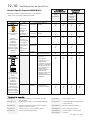
Product Warnings
Caution
Risk of electric
shock
Cont.2
Caution
Refer to
documentation
Earth/Ground
Protective
Conductor
Terminal
Hazards
DANGER! - Ignoring the following may result in injury
1.
This equipment can endanger life by exposure to
rotating machinery and high voltages.
2.
The equipment must be permanently earthed due to
the high earth leakage current, and the drive motor
must be connected to an appropriate safety earth.
3.
Ensure all incoming supplies are isolated before
working on the equipment. Be aware that there may
be more than one supply connection to the drive.
4.
There may still be dangerous voltages present at
power terminals (motor output, supply input phases,
DC bus and the brake, where fitted) when the motor
is at standstill or is stopped.
5.
For measurements use only a meter to IEC 61010 (CAT
III or higher). Always begin using the highest range.
CAT I and CAT II meters must not be used on this
product.
6.
Allow at least 5 minutes for the drive's capacitors to
discharge to safe voltage levels (<50V). Use the
specified meter capable of measuring up to 1000V dc &
ac rms to confirm that less than 50V is present between
all power terminals and earth.
7.
Unless otherwise stated, this product must NOT be
dismantled. In the event of a fault the drive must be
returned. Refer to "Routine Maintenance and Repair".
WARNING! - Ignoring the following may result in injury or damage to equipment
SAFETY
Where there is conflict between EMC and Safety requirements, personnel safety shall always take precedence.
• Never perform high voltage resistance checks on the
wiring without first disconnecting the drive from the
circuit being tested.
• Whilst ensuring ventilation is sufficient, provide
guarding and /or additional safety systems to
prevent injury or damage to equipment.
• When replacing a drive in an application and before
returning to use, it is essential that all user defined
parameters for the product’s operation are correctly
installed.
• All control and signal terminals are SELV, i.e. protected
by double insulation. Ensure all external wiring is rated
for the highest system voltage.
• Thermal sensors contained within the motor must have
at least basic insulation.
• All exposed metalwork in the Inverter is protected by
basic insulation and bonded to a safety earth.
• RCDs are not recommended for use with this product
but, where their use is mandatory, only Type B RCDs
should be used.
EMC
• In a domestic environment this product may cause
• This is a product of the restricted sales distribution class
radio interference in which case supplementary
mitigation measures may be required.
• This equipment contains electrostatic discharge
(ESD) sensitive parts. Observe static control
precautions when handling, installing and servicing
this product.
according to IEC 61800-3. It is designated as
“professional equipment” as defined in EN61000-3-2.
Permission of the supply authority shall be obtained
before connection to the low voltage supply.
CAUTION!
APPLICATION RISK
• The specifications, processes and circuitry described herein are for guidance only and may need to be adapted to the
user’s specific application. We can not guarantee the suitability of the equipment described in this Manual for
individual applications.
RISK ASSESSMENT
Under fault conditions, power loss or unintended operating conditions, the drive may not operate as intended.
In particular:
• Stored energy might not discharge to safe levels
• The motor's direction of rotation might not be controlled
as quickly as suggested, and can still be present
• The motor speed might not be controlled
even though the drive appears to be switched off • The motor might be energised
A drive is a component within a drive system that may influence its operation or effects under a fault condition.
Consideration must be given to:
• Stored energy
• Supply disconnects
• Sequencing logic
• Unintended operation
Cont.3
Contents
Contents
1
GETTING STARTED
Page
1-1
Introduction .................................................................................................. 1-1
Equipment Inspection ................................................................................... 1-1
About this Manual ........................................................................................ 1-1
Initial Steps .............................................................................................................1-1
How the Manual is Organised .................................................................................1-2
Associated Documentation ........................................................................... 1-2
2
AN OVERVIEW OF THE SERVO DRIVE
2-1
Component Identification ............................................................................. 2-1
Control Features ........................................................................................... 2-2
Understanding the Product Code ................................................................. 2-4
3
INSTALLING THE SERVO DRIVE
3-1
EMC Installation Hints .................................................................................. 3-1
Mechanical Installation ................................................................................ 3-2
Mounting the Servo Drive ........................................................................................3-2
Minimum Air Clearances .........................................................................................3-3
Electrical Installation .................................................................................... 3-4
4
Wiring the Servo Drive.............................................................................................3-6
OPERATING MODES
4-1
Control Philosophy........................................................................................ 4-1
Operating Modes.......................................................................................... 4-1
Configuring the OPTO Inputs and Outputs (X10)......................................... 4-2
Function Diagrams for Inputs/Outputs......................................................... 4-5
Motor Overload Protection ........................................................................... 4-6
5
INITIAL SET-UP
5-1
Connecting the X15/RS232 EASYRIDER Set-up Service ................................ 5-1
Pre-Operation Checks .................................................................................. 5-2
Inital Set-up with EASYRIDER .................................................................... 5-3
6
Commissioning Instructions .....................................................................................5-3
PROGRAMMING YOUR APPLICATION
6-1
EASYRIDER Software ..................................................................................... 6-1
Cont.5
Contents
Contents
Page
Autopilot.................................................................................................................6-1
BIAS Programming Language ..................................................................................6-2
EASYRIDER Main Screen - Menu Options ..................................................... 6-4
Parker SSD Programming Language BIAS................................................... 6-5
BIAS Commands .....................................................................................................6-6
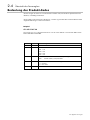
General Keyboard Definitions ..................................................................... 6-6
General Keyboard Definitions ..................................................................... 6-7
BIAS Editor Keyboard Shortcuts ................................................................... 6-7
Diagnostics ................................................................................................... 6-8
7 Segment Display ..................................................................................................6-8
Resetting the Drive ..................................................................................... 6-12
Error Signals .........................................................................................................6-12
Trouble Shooting ........................................................................................ 6-13
7
DIAGNOSTICS AND FAULT FINDING
7-1
Resetting a Trip Condition ............................................................................ 7-1
Trip Diagnostics ............................................................................................ 7-1
Fault Finding................................................................................................. 7-4
Re-actions of Supply Voltage Supervising Functions ................................... 7-5
History Status Memory.................................................................................. 7-5
8
ROUTINE MAINTENANCE AND REPAIR
8-1
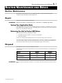
Routine Maintenance.................................................................................... 8-1
Repair ........................................................................................................... 8-1
Saving Your Application Data ..................................................................................8-1
Returning the Unit to Parker SSD Drives....................................................................8-1
Disposal ........................................................................................................ 8-1
9
10
11
ACCESSORIES
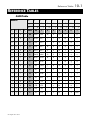
REFERENCE TABLES
9-1
10-1
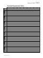
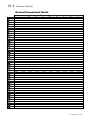
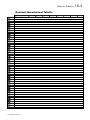
ASCII Table...........................................................................................................10-1
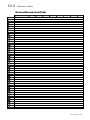
Decimal/Hexadecimal Table..................................................................................10-2
TECHNICAL SPECIFICATIONS
11-1
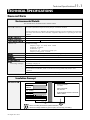
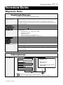
General Data .............................................................................................. 11-1
Environmental Details............................................................................................11-1
Insulation Concept ................................................................................................11-1
Cont.6
Contents
Contents
Page
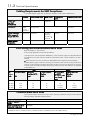
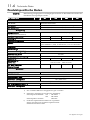
Cabling Requirements for EMC Compliance ...........................................................11-2
Fuse Rating and Recommended Wire Sizes .............................................................11-2
Terminal Block Wire Sizes ......................................................................................11-2
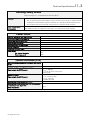
Earthing/Safety Details ..........................................................................................11-3
Power Circuit ........................................................................................................11-3
Control Terminals (X10).........................................................................................11-3
Resolver Conversion (X30) .....................................................................................11-4
Digital Communication (X15, X20/X21)..................................................................11-4
X40/X41 - Multi-function Input/Output ...................................................................11-4
Controller System..................................................................................................11-4
Digital Control ......................................................................................................11-5
Product Specific Data .................................................................................. 11-6
12
EMC Compliance..................................................................................................11-6
Input ....................................................................................................................11-6
Output..................................................................................................................11-6
Brake Circuit.........................................................................................................11-6
CERTIFICATION FOR THE SERVO DRIVE
12-1
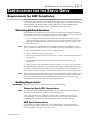
Requirements for EMC Compliance ............................................................ 12-1
Minimising Radiated Emissions ..............................................................................12-1
Earthing Requirements...........................................................................................12-1
Cabling Requirements ...........................................................................................12-2
EMC Installation Options .......................................................................................12-2
Requirements for UL Compliance ............................................................... 12-6
European Directives and the CE Mark........................................................ 12-7
13
CE Marking for Low Voltage Directive ....................................................................12-7
CE Marking for EMC - Who is Responsible? ...........................................................12-7
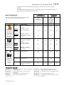
Which Standards Apply?........................................................................................12-8
Certificates .........................................................................................................12-11
APPLICATION NOTES
13-1
Controlling Synchronous Motors................................................................. 13-1
Using Line Chokes ...................................................................................... 13-1
Using Output Contactors............................................................................. 13-1
Using Motor Chokes ................................................................................... 13-1
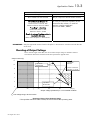
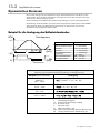
Dynamic Braking ........................................................................................ 13-2
14
Example Brake Resistor Calculation........................................................................13-2
Derating of Output Voltage ...................................................................................13-3
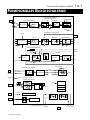
FUNCTIONAL BLOCK DIAGRAM
14-1
Cont.7
Contents
Contents
Cont.8
Page
Getting Started
1-1
GETTING STARTED
1
Introduction
The 631 Digital Servo Drive is designed to control Parker SSD Drives approved AC Brushless
Servo Motors. It is available in a range of current ratings from 1 to 6 Amps.
Set-up
The EASYRIDER software is used to set-up the drive. An “Autopilot” set-up wizard can be
started when using the software.
Programming
The “BIAS” progamming language is contained in EASYRIDER which provides for up to
1500 lines of program code.
Operation
The unit is operated remotely using the analog/digital inputs and outputs via a PLC, for
example. Multiple units can be controlled using RS232, CAN-Bus or Incremental Bus.
Four operating modes offer various speed, torque and position controls.
There is a seven-segment diagnostic display for trip and fault finding information.
The internal RFI filter offers enhanced EMC compliance without the need for additional
external components.
An internal dynamic brake resistor is provided.
Equipment Inspection
•
•
Check for signs of transit damage
Check the product code on the rating label conforms to your requirement.
If the unit is not being installed immediately, store the unit in a well-ventilated place away from
high temperatures, humidity, dust, or metal particles.
Refer to Chapter 2: “An Overview of the Servo Drive” to check the rating label/product code.
Refer to Chapter 8: “Routine Maintenance and Repair” for information on returning damaged
goods.
Refer to Chapter 9: “Accessories” to check for the correct items.
About this Manual
This manual is intended for use by the installer, user and programmer of the 631 Servo Drive. It
assumes a reasonable level of understanding in these three disciplines.
Note: Please read all Safety Information before proceeding with the installation and operation
of this unit.
Enter the “Model No” from the rating label into the table at the front of this manual. It is
important that you pass this manual on to any new user of this unit.
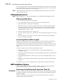
Initial Steps
Use the manual to help you plan the following:
Installation
Know your requirements:
•
•
•
631 Digital Servo Drive
certification requirements, CE/UL/CUL conformance
conformance with local installation requirements
supply and cabling requirements
1-2
Getting Started
Operation
Know your operator:
•
how is it to be operated, RS232, CAN-Bus?
•
what level of user is going to operate the unit?
Programming (Operator Station or suitable PC programming tool only)
Know your application:
•
select the appropriate Operating Mode
•
plan your “programming”
•
enter a password to guard against illicit or accidental damage
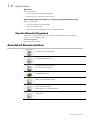
How the Manual is Organised
The manual is divided into chapters and paragraphs. Page numbering restarts with every
chapter, i.e. 5-3 is Chapter 5, page 3.
Further descriptions,
that relate to this document.
Associated Documentation
UL:4.2.2
Absolute encoder with CAN
UL:7.5.3.3
Bus Interface CAN for 631
UL:9.5.1
Intelligent Operator-Terminal
IBT - Product Description
UL: 10.6.4
EASYRIDER software
UL: 10.6.5
BIAS - Command Description
UL: 10.6.6
Serial transfer protocol
EASY-serial 631 - Product Manual
UL: 12
Accessories
631 Digital Servo Drive
An Overview of the Servo Drive
2-1
AN OVERVIEW OF THE SERVO DRIVE
2
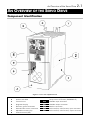
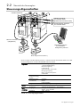
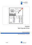
Component Identification
Figure 2-1 View of Component Parts
1
2
3
4
5
6
7
8
Main servo drive assembly
Product code label
Terminal cover
Diagnostic display
Electronic ground connection
External brake resistor connection
Adjustable mounting clip
Control terminal (X10)
631 Digital Servo Drive
9
X15/RS232
X20
X21
X30
X40
X41
Power terminal (X1)
Set-up service connection (EASYRIDER )
CAN-Bus input connection
CAN-Bus output connection
Resolver connection
Pulse interface, multi-function, input connection
Pulse interface, multi-function, output connection
2-2
An Overview of the Servo Drive
Control Features
CAN-Bus terminator
X
2
0
X
2
1
X
4
0
X3 0
X
2
0
X
4
1
CAN-Bus connection
to next 631 controller
(last controller is terminated)
X
2
1
X
4
0
X3 0
X
4
1
Encoder/Stepper connection
to next 631 controller
X15/RS232
X15/RS232
Resolver Connection
(mandatory)
POWER
EASYRIDER software
used to configure
each 631 individually
POWER
Motor 1
Motor 2 (synchronised to Motor 1)
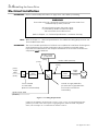
The Servo Drive is controlled via RS232, CAN-Bus or Incremental Bus using a PLC. It is
configured using the EASYRIDER® Windows software.
General
Operating
Functions
Setup, Service,
Programming
Communications
Interfaces
Protection
Inputs/
Outputs
Diagnostics
Trip Conditions
Functions
Inputs
Outputs
Pulse/direction Input
±10V speed control
Torque control
Position control
Synchronous Encoder
Motion control
BIAS - programming language
CAM profiling
EASYRIDER® Windows software
CAN-Bus
RS232
Incremental Bus
Complete diagnostic options
Heatsink overtemperature and
Multiple protection functions - refer to Chapter 7
±10V (12 bit) setpoint
4 In: 24V DC
2 Out: 24V DC
Table 2-1 Control Features
631 Digital Servo Drive
An Overview of the Servo Drive
2-3
631 Servo Drive
Custom-made Software
PLC
⌧
CAN-Bus
EASYRIDER
⌧
RS232
current-loop
X20/X21
speed-loop
position-loop
X15
PLC I/O ±10V (24V)
PLC
X10
Instructions
Diagnostics
Setup
⌧
Programming
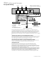
Figure 2-2 Communications Options
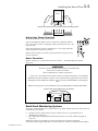
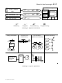
Conventional Control
(analog setpoint value)
Point-to-Point
Position Control
Synchronisation
(electronic gearbox)
CAN-Bus Network
Unit X
+10V
M
-10V
Pos.1
CAN
Unit Y
Pos.2
631
M
631
631
R
1:X
Pulse Control
Stepper motor
control or
incremental
encoder
Pos Y
CAM Profiling
631
AC Servo
Pos X
Figure 2-3 Typical Applications
631 Digital Servo Drive
2-4
An Overview of the Servo Drive
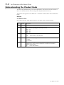
Understanding the Product Code
The unit is fully identified using a five block alphanumeric code which records how the Servo
Drive was calibrated, and its various settings when despatched from the factory.
The Product Code appears as the “Model No.”. Each block of the Product Code is identified as
below:
Example
631-002-230-F-00
Servo Drive Type 631, rated output current 2A, AC supply 230V, with internal filter.
Block
No.
Variable
1
631
2
XXX
Description
Generic product
Three numbers specifying the rated output current
001 = 1A
002 = 2A
004 = 4A
006 = 6A
3
XXX
Three numbers specifying the nominal input voltage rating:
230
4
X
220 to 240V (±10%) 50/60Hz
One character specifying the use of the Internal EMC RFI Filter:
F = Filter
0 = No Filter
5
XX
Two digits specifying mechanical package including livery and mechanical
package style, and any option installed over and above the standard
features of the product:
00
Parker SSD Standard
631 Digital Servo Drive
Installing the Servo Drive
3-1
INSTALLING THE SERVO DRIVE
3
IMPORTANT: Read Chapter 12: “Certification for the Servo Drive” before installing this unit.
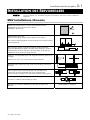
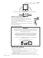
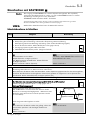
EMC Installation Hints
All components are mounted on a mounting plate (minimum
thickness 3mm) inside a steel cubicle.
3mm
Ensure good grounding of the complete system, including the ground
connections between the cubicle and machine.
If more than one mounting plate, interconnect with copper rails.
Place all wires and cables as close as possible to any grounded metal
planes. Position control cables close to grounded metal parts when
exiting the control cubicle.
Separate “dirty”, “clean” and “sensitive” cables if possible by at least
30mm. Cables should cross at 90°.
Avoid cable loops, especially between the line filter and drive which
should be as close and as short as possible (drilled).
90°
0,3 m
Only remove the required length of screen from the end of the cable.
8 cm max
Make screen connections as advised in this manual. Keep screened
cables as short as possible, ground screens at both ends. For long
cables, make additional screened connections along the cable
length.
Connect screens to good quality grounding points. Use U-clips to
give a 360° connection.
Connect any unused wires in the cables to ground.
Use only Parker SSD Drives cables for motor and resolver.
631 Digital Servo Drive
Refer to Chapter 9: “Accessories”
3-2Installing the Servo Drive
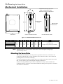
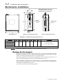
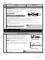
Mechanical Installation
Adjustable mounting clip can be
easily re-positioned to allow
different mounting configurations
W
H1
H
H2
Fixing hole
centres
H3
DIN mounting
dimensions
W1
D
SIDE VIEW
PANEL MOUNTING VIEW
DIN MOUNTING VIEW
Figure 3-1 Mechanical Dimensions for 631
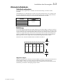
631 Model Number
H
H1
H2
H3
W
W1
D
631 -002- 230- ....
183.0
188.0
205.0
151.0
72.0
36.0
175.0
Use M5 fixings
631 -004- 230- ....
(7.2)
(7.4)
(8.1)
(5.9)
(2.8)
(1.4)
(6.9)
Weight 1.5kg (3.3lb) approximately
631 -001-230- ....
Fixings
Mounting holes 5.5mm
631 -006- 230- ....
All dimensions are in millimetres (inches)
Note: Additional space is required to the front of the unit for the signal mating plugs,
approximately 45mm.
Mounting the Servo Drive
The unit must be installed in a vertical position to guarantee the best air circulation for the
cooling ribs of the heat sink. Vertical installation above other drive racks or above other heat
producing devices can lead to overheating.
You must install the unit inside a suitable cubicle. The inside of this cubicle must be free from
dust, corrosive fumes, gases, and all liquids including condensation.
If the unit is being installed in a place where condensation is likely, install a suitable anticondensation heater. The heater must be SWITCHED OFF during normal operation. Automatic
switch off is recommended.
631 Digital Servo Drive
Installing the Servo Drive
3-3
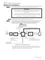
Minimum Air Clearances
Cubicle Size
The digital servo drive is protected against damage caused by overheating.
There is a thermal sensor installed on the heat sink. When the temperature rises to >95°C, the
drive is automatically switched off. This setting cannot be changed. Use a cabinet of the correct
size for adequate air circulation, see below.
631 Model Number
Volume of Cubicle
(minimum)
631 -001- 230- ....
631 -002- 230- ....
0.12m³
631 -004- 230- ....
631 -006- 230- ....
Ventilation
The servo drive gives off heat in normal operation and must therefore be mounted to allow the
free flow of air through the ventilation slots and heatsink. Maintain minimum clearances for
ventilation as shown below to ensure heat generated by other adjacent equipment is not
transmitted to the Servo Drive. Be aware that other equipment may have its own clearance
requirements. When mounting two or more 631s together, these clearances are additive.
Ensure that the mounting surface is normally cool.
100mm / 4"
631
631
631
631
631
100mm / 4"
General Rule:
It is better to place heat-producing devices low down inside an enclosure to support internal
convection, which will spread the heat. If placing devices up high is unavoidable, you should
consider increasing the (upper) dimensions of the cubicle, or installing fans.
631 Digital Servo Drive
3-4Installing the Servo Drive
Electrical Installation
IMPORTANT: Please read the Safety Information on page Cont. 3 & 4 before proceeding.
WARNING!
Ensure that all wiring is electrically isolated and cannot be made “live”
unintentionally by other personnel.
All control/resolver/motor thermistor inputs,
i.e protected by double insulation are SELV.
Do not connect to non-SELV circuits.
(Refer to Chapter 11: “Technical Specifications” - Insulation Concept).
Note: Refer to Chapter 11: “Technical Specifications” for additional Cabling Requirements and
Terminal Block Wire Sizes.
IMPORTANT: The use of variable speed drives of all kinds can invalidate the certification for dangerous
areas (apparatus group and/or temperature class) of explosion-protected motors.
Inspection and certification for the complete installation of servo motors and electronic
components must be obtained.
brake resistor
(if required)
(noisy)
(noisy)
resolver cable (sensitive)
(noisy)
power
supply
cable
line
choke
(optional)
(clean)
631
motor
choke
(if requiredl)
motor
cable
(noisy)
motor
internal ac supply EMC filter
fuse or suitable
circuit breaker
(RCD not recommended)
(an external ac supply EMC filter
must not be used with the
internal filter)
signal/control cable
(sensitive)
Figure 3-2 Cabling Requirements
Cables are considered to be electrically sensitive, clean or noisy. You should already have
planned your cable routes with respect to segregating these cables for EMC compliance.
If not, refer to Chapter 12: “Certification for the Servo Drive”.
631 Digital Servo Drive
Installing the Servo Drive
3-5
631
Remove Terminal Cover by pressing here and pulling down
Using Cage Clamp Terminals
Remove the terminal cover as shown above.
Insert a flat-bladed screwdriver (size 3.5 mm max.) inside the smallest
hole. Lever the screwdriver, keeping it firmly pressed into the hole. The
cage will open.
Insert the stripped wire (5mm to 6mm/0.22in.) or wire crimp inside the
cage keeping the screwdriver in position.
Remove the screwdriver. Note the cage provides the correct force for a
secure connection.
Motor Thermistor
Refer to Chapter 12: “Certification for the Servo Drive” - Solid State Motor Overload
Protection.
WARNING!
The servo drive thermistor connections are for SELV only.
Parvex servo motors are SELV,
other manufacturer’s motors may not be.
If you use a non-Parvex servo motor, make sure that the thermistor is insulated to
SELV from live parts inside the motor. If not, the thermistor signals have to be wired
separately and an additional isolation circuit must be provided before connecting to
X30.
Make sure that pins 2 and 6 of X30 are only served by SELV insulated cable leads.
resolver cable (without thermistor connections)
thermistor wires
X30
631
SELV Isolation
motor
Earth Fault Monitoring Systems
We do not recommend the use of circuit breakers (e.g. RCD, ELCB, GFCI), but where their use
is mandatory, they should:
•
Operate correctly with dc and ac protective earth currents (i.e. type B RCDs as in
Amendment 2 of IEC755).
• Have adjustable trip amplitude and time characteristics to prevent nuisance tripping on
switch-on.
When the ac supply is switched on, a pulse of current flows to earth to charge the
internal/external ac supply EMC filter’s internal capacitors which are connected between phase
631 Digital Servo Drive
3-6Installing the Servo Drive
and earth. This has been minimised in Parker SSD Drives’ filters, but may still trip out any
circuit breaker in the earth system. In addition, high frequency and dc components of earth
leakage currents will flow under normal operating conditions. Under certain fault conditions
larger dc protective earth currents may flow. The protective function of some circuit breakers
cannot be guaranteed under such operating conditions.
WARNING!
Circuit breakers used with VSDs and other similar equipment are not suitable for
personnel protection. Use another means to provide personal safety. Refer to
EN50178 (1998) / VDE0160 (1994) / EN60204-1 (1994)
Wiring the Servo Drive
Earth Connections
WARNING!
Due to the working principle of servo drives or filters, there will be an eart
leakage current exceeding 10mA dc, 3.5mA ac.
IMPORTANT: Refer to “Earth Fault Monitoring Systems”. page 3-5.
The wiring terminals accept a maximum conductor size of 12 AWG (3.2mm²).
The servo drive, when fitted with an internal ac supply EMC filter, is only suitable for earth
referenced supplies (TN).
Refer to Chapter 12: “Certification for the Servo Drive” for information on earthing
requirements.
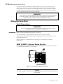
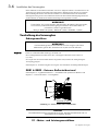
DBR1 & DBR2 - External Brake Resistor
Refer to Chapter 13: “Application Notes” - Dynamic Braking for selection details and Chapter
11: “Technical Specifications” - Power Details.
DBR1
DBR2
Top View of 631
Figure 3-3 External Brake Resistor Terminals
Caution
The resistor should be mounted on a heatsink (back panel) and covered to prevent injury
from burning.
631 Digital Servo Drive
Installing the Servo Drive
3-7
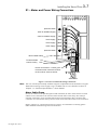
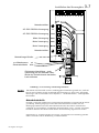
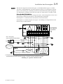
X1 - Motor and Power Wiring Connections
1 2 3 4 5 6
7 8 9 10
X1
protective earth
230V ac 50/60Hz supply
L1
230V ac 50/60Hz supply
L2/N
motor supply
M1/U
motor supply
M2/V
motor supply
M3/W
protective earth
Motor Cable Clamp
To Motor Brake
control circuitry
red
blue
Screen Connections - ensure good
connection with conductive surface
on the cubicle, remove varnish.
Power
Servo Motor
Figure 3-4 631 Power and Earth Wiring Connections
Note: The unit must be permanently earthed using two independent earth conductors using X1.
Protect the incoming mains supply using a suitable fuse or circuit breaker as shown in
Chapter 11: “Technical Specifications” - Power Details.
Motor Cable Clamp
In order to conform to the specified generic EMC standards, the motor cable must be screened
and the screen connected to both the motor frame and the motor cable clamp. This clamp is
internally connected to power terminals PE (Protective Earth) and provides convenient 360°
connection. It is used for the motor protective earth, motor and control cable screen connections.
Refer to Chapter 12: “Certification for the Servo Drive” for information on meeting generic
EMC standards and minimising electrical interference.
631 Digital Servo Drive
3-8Installing the Servo Drive
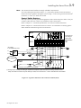
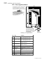
X10 - Control Wiring Connections
X10
Functional Earth connected to
cubicle backplate providing clean earth
for electronic ground and screens
1 2 3 4 5 6
L1
L2/N
7 8 9 10
Control Cable
Retainer
M1/U
M2/V
M3/W
Screen Connections:
ensure good connection
with conductive surface
on the cubicle.
Remove varnish.
Control
Figure 3-5 631 Control Wiring Connections
Pin
Type
Function
1
±10V, Ri - 10kΩ
ANALOG IN, differential to pin 2
referenced to GND
2
±10V, Ri - 10kΩ
ANALOG IN, differential to pin 1
referenced to GND
3
0V PLC
External supply for digital i/o,
related to pin 4
4
24V DC PLC
External supply for digital i/o,
related to pin 3
5
Opto-OUT
Configurable (s. 3.1.1)
6
Opto-OUT
Configurable (s. 3.1.1)
7
Opto-IN
ACTIVE, non-configurable
activates motor power when high
8
Opto-IN
Configurable (s. 3.1.1)
9
Opto-IN
Configurable (s. 3.1.1)
10
Opto-IN
Configurable (s. 3.1.1)
631 Digital Servo Drive
Installing the Servo Drive
3-9
Note: Use screened control cables to comply with EMC requirements.
All control and signal terminals are SELV, i.e., protected by double/re-inforced insulation.
Ensure all wiring is rated for the highest system voltage. Control wiring of between 0.08 mm2
(28 AWG) - 2.5 mm2 (14 AWG) can be used.
Control Cable Retainer
This clip is used to provide guaranteed segregation of the control and power cables. It may be
rotated in either direction to allow easy installation of the control cables.
Refer to Chapter 11: “Technical Specifications” for Control Terminal information.
Refer to Chapter 12: “Certification for the Servo Drive” for information on meeting generic
EMC standards and minimising electrical interference.
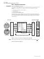
631
0V
I/O Functions
according to
set-up with
EASYRIDER
1
X10
2
3
4
5
6
7
8
9 10
I/O supply
to be installed by User
L1
N
DC +24V PLC
~
=
0V PLC
*
SELV Isolation
PLC
Analog
Digital
Functions according to user-software
* Analog Output. Polarity according to requirement. Setpoint output and input are working related to earth.
It may be useful to connect one pole directly to earth, but not to the PLC - refer to manufacturer's information.
Figure 3-6 Typical Connection to the Control Terminals (X10)
631 Digital Servo Drive
3-10Installing the Servo Drive
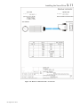
X30 - Resolver Connection
IMPORTANT: Refer to the WARNING on page 3-5.
The resolver provides a digital value for the rotor position to within one revolution, evaluation:
12 or 14 bit. It is adjustable in the Configuration Menu in the EASYRIDER® Windows
software.
•
•
•
•
commutation according to pole pair number
actual speed value
incremental position output
position value for position regulation
The supplied resolver cable is plugged in to the front of the 631 (socket X30), and into the
socket on the Parker SSD Drives approved servo motor. This connection must be made for the
631 to control the operation of the motor. The cable contains wiring for the resolver and the
motor thermistor.
motor end
front
8
7
9
1
2
10
12
11
6
3
5
4
1
2
9
8
12
10
7
11
3
4
6
5
solder side
controller end (X30)
front
Pin No.
Colour
Function
1
2
3
4
8
7
5
6
9
10
11
12
white
brown
green
yellow
grey
pink
red
blue
sin +
sin cos +
cos carrier +
carrier PTC optional
PTC optional *
Pin No.
screen
4
8
3
7
5
9
2
6
1
6
7
8
9
1
2
3
4
5
screens can be connected to ground
with U-clip or gland using 360°connection
1
2
3
4
5
6
7
8
9
solder side
Figure 3-7 Resolver Connections (as supplied cable model KIR)
Note: The plug type shown above is for use with Parker SSD Drives motor types AC Mn only.
Refer to the Warning on page 3-5.
631 Digital Servo Drive
Installing the Servo Drive
Figure 3-8 Resolver connections X30 - AC M series
631 Digital Servo Drive
3-11
3-12Installing the Servo Drive
Green resolver cable for Parvex standard motors
with Parker SSD Drives servo drives
Figure 3-9 Resolver connections X30 - NX series
631 Digital Servo Drive
Installing the Servo Drive
3-13
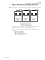
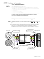
X40/41 - Multi-function Input/Output Connections
This connection provides encoder emulation, encoder input and stepper motor interface.
Note: Refer to Chapter 11: “Technical Specifications” - X40/X41 - Multi-function Input/Output.
GND
GND
X40
X41
X40
GND
X41
X40
X41
Incremental-Out
Incremental-IN
Incremental-IN
MASTER
SLAVE 1
SLAVE 2
631
631
631
mount units side-by-side if possible
keep cables as short as possible
X40/41 signals are referred to PE
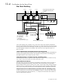
Figure 3-8 Application Example
To synchronise several 631 servo drives, connect the X40/41 sockets as shown using the
specified cables. The 631 is configured using EASYRIDER software .
The X40/X41 input/output functions are configurable using the EASYRIDER software.
Functions:
Mode 0 Incremental Output
Mode 1 Incremental Input
Mode 2 Step Control Pulse/Direction
Mode 3 Step Control Pulse (+) ( -)
631 Digital Servo Drive
3-14Installing the Servo Drive
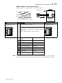
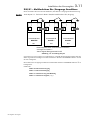
X40/41 Mode 0 - Incremental Output
• Incremental encoder simulation for processing in positioning modules
• Standard: 1024 increments; other selectable pulse numbers are 512, 256, 128,
64,2048
GND
PLC
A
/A
B
/B
IN
Encoder Emulation,
based on Resolver
conversion
Incremental Encoder inputs or outputs
X40
8-pole Modular Jack,
screened
1
8
X41
X40
Z
/Z
Pin
GND
/Z
Z
/B
B
/A
A
5VI
Function
EASYRIDER® Windows software X40 mode = 0
X40 and X41 are identical and internally switched
in parallel.
(X40 = X41) therefore wiring is very easy.
Incremental OUT
631
X41
8-pole Modular Jack,
screened
1
8
1
2
3
4
5
6
7
8
internal connection to
GND
GND
inverted 0-Index
0-Index
Channel B inverted
Channel B
Channel A inverted
Channel A
Output supply voltage
5.5V dc max. 150mA
GND
/Z
Z
/B
B
/A
A
5VI
Case: Screened
OUT
OUT
OUT
OUT
OUT
OUT
5VI
/Z
Z
/B
B
/A
A
Rating Note
The capability of input frequency of any connected device must at least meet the selected value
of pulse outputs (increments) on X40.
n = maximum speed (rpm)
x = increments e.g. 1024
f = output frequency at X40/41 4,5,6,7
Formula:
f =
n* x
= [Hz]
50
Example: n = 4000 rpm
f =
4000 * 1024
= 81920 H z
50
631 Digital Servo Drive
Installing the Servo Drive
3-15
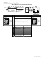
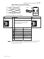
X40/41 Mode 1- Incremental Input
Parameter area of the input signals is 10 - 1,000,000 increments
GND
Encoder IN
A
/A
B
/B
X40
Z
/Z
Encoder
Mode = 1
Incremental IN
631
Incremental Encoder inputs or outputs
X40
Pin
8-pole Modular Jack,
screened
1
8
GND
/Z
Z
/B
B
/A
A
5VI
X41
Function
X41
EASYRIDER X40 mode = 1
8-pole Modular Jack,
screened
X40 and X41 are identical and internally switched
in parallel.
(X40 = X41) therefore wiring is very easy.
1
8
internal connection to
GND
GND
/Z
Z
/B
B
/A
A
5VI
Case: Screened
1
GND
2
inverted 0-Index
OUT /Z
3
0-Index
OUT Z
4
Channel B inverted
OUT /B
5
Channel B
OUT B
6
Channel A inverted
OUT /A
7
Channel A
OUT A
8
Output supply voltage
5.5V dc max. 150mA
5VI
Note: The operation of incremental encoders when using long cables may cause a voltage
drop of the encoder power supply. We suggest using an external supply if necessary.
631 Digital Servo Drive
3-16Installing the Servo Drive
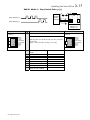
X40/41 Mode 2 - Step-Control Pulse/Direction
GND
Pulse
Direction
1
turn direction (-)
1 set-up time
X40
8-pole Modular Jack,
screened
1
8
2.5µs
Pin
GND
IN /R
IN R
Out Ready
Out /Ready
IN P
IN /P
5VI
2
turn direction (+)
X41
X40
Steps in
Pulse/Direction
Mode = 2
2 hold time = 0
Function
EASYRIDER X40 mode = 2
X40 and X41 are identical and internally switched
in parallel.
(X40 = X41) therefore wiring is very easy.
1
2
3
4
5
6
7
8
internal connection to
GND
GND
Direction inverted
Direction
Drive Active
Drive Active inverted
Pulse
Pulse Inverted
Output supply voltage
5.5V dc max. 150mA
631
Stepper
Motor
Control
X41
8-pole Modular Jack,
screened
1
8
GND
IN /R
IN R
Out Ready
Out /Ready
IN P
IN /P
5VI
Case: Screened
IN /R
IN R
Out Ready
Out /Ready
IN P
IN /P
5VI
631 Digital Servo Drive
Installing the Servo Drive
3-17
X40/41 Mode 3 - Step-Control Pulse (+)(-)
GND
pulse direction (+)
pulse direction (-)
X40
8-pole Modular Jack,
screened
1
8
X41
X40
Steps In
Pulse (+) (-)
Mode = 3
Pin
GND
IN /P+
IN P+
Out Ready
Out /Ready
IN PIN /P5VI
Function
EASYRIDER X40 mode = 3
X40 and X41 are identical and internally switched
in parallel.
(X40 = X41) therefore wiring is very easy.
X41
8-pole Modular Jack,
screened
1
8
1
2
3
4
5
6
7
8
631 Digital Servo Drive
631
Stepper
Motor
Control
internal connection to
GND
GND
Pulse (+) Inverted
Pulse (+)
Drive Active
Drive Active inverted
Pulse (-)
Pulse (-) inverted
Output supply voltage
5.5V dc max. 150mA
Case: Screened
IN /P+
IN P+
Out Ready
Out /Ready
IN PIN /P5VI
GND
IN /P+
IN P+
Out Ready
Out /Ready
IN PIN /P5VI
3-18Installing the Servo Drive
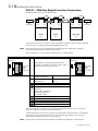
X20/21 - CAN-Bus Digital Interface Connections
Standard fieldbus protocol CAN-Bus interface.
GND
GND
GND
124 Ohm
Bus
Termination
CAN-Bus
X20
X21
X20
NODE 1
631
X21
124 Ohm
X20
X21
NODE 2
LAST NODE
631
631
Bus
Termination
To network several 631 servo drives, connect the X20/21 sockets as shown using the specified
cables. The 631 is configured using EASYRIDER software .
Note: The daisy-chain wiring is intended to be used for local bus distribution. Long bus
extensions should not cross daisy-chain sections.
Refer to Chapter 11: “Control and Communications” for cabling details.
X20
8-pole Modular Jack,
screened
Pin Function
1
CAN_GND
CAN_L
CAN_H
8
CAN_GND
GND
X21
8-pole Modular Jack,
screened
X20 and X21 are identically and internal
switched in parallel with all pins, (X20 = X21)
therefore bus-wiring is very easy.
1
CAN_GND
CAN_L
CAN_H
8
CAN_GND
GND
internal connection to
GND via capacitor
Operating Conditions
and Protocol
1
2
3
4
5
6
7
8
Case: Screened
See documentation
7.5.3.x
CAN_GND
Reference
galvanically separated.
Coupling-resistor to
PE / GND: 1MΩ
CAN_L (dominant low)
CAN_H (dominant high)
CAN_GND, like Pin 3
This Pin Assignment is related to “CiA Draft Recommendation DR-303, V0.1 / 26.10.98”.
The wires on Pins 3/6 and 4/5 should be twisted pairs.
A defined quiescence level on the bus must be guaranteed for communication. You should use
terminal resistors on both ends of the line. Use special bus plugs that have a resistance of
approximately 124Ω between CAN_L and CAN_H.
Note: A plug with an internal terminal resistor is available see Chapter 9: “Accessories”.
631 Digital Servo Drive
Operating Modes
4-1
OPERATING MODES
4
Control Philosophy
631 servo drive
using a selection of all available functions:
631 servo drive
using:
Resolver
8
encoder
emulation
RS232
CAN-Bus
Comms link
8
multi-functional
pulse interface
(encoder,
stepper etc.)
X10
Resolver
analog
input
digital i/o
RS232
X10
analog
input
digital i/o
Operating Modes
1&2
REMOTE CONTROL
Operating Modes
4&5
Figure 4-1 Remote Control
Operating Modes
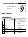
The Operating Mode for the unit is selected using the EASYRIDER software menu:
“Commissioning/General”.
The 631 unit does not use Modes 0 and 3. If you attempt to select these, the unit will default to
the set-up for Mode 1 - speed control.
Mode No.
Operating Mode
Setpoint Source
BIAS
0
Reserved (as Mode 1)
1
speed control
analog Input
no
2
current control
analog Input
no
3
Reserved (as Mode 1)
4
position control using Position Blocks
selectable source using
EASYRIDER (analog or
digital)
no
5
position control using BIAS Program
selectable source using
EASYRIDER (analog or
digital)
yes
Note: In Operating Mode 5, you can download example BIAS programs from a library, or
using the BIAS Editor in EASYRIDER you can create your own programs.
631 Digital Servo Drive
4-2
Operating Modes
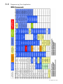
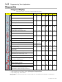
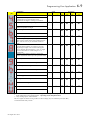
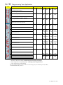
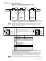
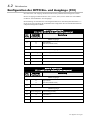
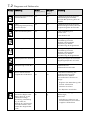
Configuring the OPTO Inputs and Outputs (X10)
The OPTO Input and Output functions must be configured for use with each Operating Mode.
The Input/Output functions for terminals X10.5, X10.6, X10.8, X10.9 and X10.10 are selected
in the menu: “Commissioning/Input -Output”.
The function of each input/output is determined by selecting a number from 0 to 5. The tables
below show the possible selections to be used with each Operating Mode.
MODE 1 - SPEED CONTROL
(X10.1 and X10.2 are evaluated as the speed setpoint)
X10
Terminal
No.
EASYRIDER
Function
No.
Description
OPTO outputs
5
0
4
DRIVE READY (1 = drive can be activated)
ACTIVE OK (1 = power stage activated)
6
-
-
OPTO inputs
7
Fixed input
ACTIVE - activates motor power when high against X10.4
8
4
LIMIT SWITCH +
9
4
LIMIT SWITCH -
10
-
-
MODE 2 - CURRENT CONTROL
(X10.1 and X10.2 are evaluated as the current setpoint)
X10
Terminal
No.
EASYRIDER
Function
No.
Description
OPTO outputs
5
0
4
DRIVE READY (1 = drive can be activated)
ACTIVE OK (1 = power stage activated)
6
-
-
OPTO inputs
7
Fixed input
ACTIVE - activates motor power when high against X10.4
8
4
LIMIT SWITCH +
9
4
LIMIT SWITCH -
10
-
-
631 Digital Servo Drive
Operating Modes
4-3
MODE 4 - POSITION CONTROL (POSITION BLOCKS)
X10
Terminal
No.
EASYRIDER
Function
No.
Description
OPTO outputs
5
0
1
3
4
DRIVE READY (1 = drive can be activated)
INITIALISED (1 = move reference activated)
TRAIL CONTROL (1 = position within trail window)
ACTIVE OK (1 = power stage activated)
6
0
1
3
4
POSITION REACHED (1 = position within position window)
INITIALISED (1 = move reference executed)
TRAIL CONTROL (1 = position within trail window)
TARGET POSITION REACHED (1 = target position reached)
OPTO inputs
631 Digital Servo Drive
7
Fixed input
ACTIVE - activates motor power when high against X10.4
8
0
1
2
4
Free programmable in operating mode 5 BIAS
REFERENCE SENSOR
STROBE INPUT (slope 0 - >1) for the BIAS block
LIMIT SWITCH +
9
0
1
2
3
4
5
Free programmable in operating mode 5 BIAS
REFERENCE SENSOR
BIAS block selection data 2^0
START (slope 0 - >1) for BIAS move commands
LIMIT SWITCH Latch input 1 (see sensor functions in BIAS)
10
0
1
2
3
5
Free programmable in operating mode 5 BIAS
REFERENCE SENSOR
BIAS block selection data 2^1
Reset drive fault
Latch input 2 (see sensor functions in BIAS)
4-4
Operating Modes
MODE 5 - POSITION CONTROL (BIAS PROGRAM)
X10
Terminal
No.
EASYRIDER
Function
No.
Description
OPTO outputs
5
0
1
2
3
4
DRIVE READY (1 = drive can be activated)
INITIALISED (1 = move reference activated)
BIAS-OUTPUT 5 (set/reset by BIAS program)
TRAIL CONTROL (1 = position within trail window)
ACTIVE OK (1 = power stage activated)
6
0
1
2
3
4
5
POSITION REACHED (1 = position within position window)
INITIALISED (1 = move reference activated)
BIAS-OUTPUT 6 (set/reset by BIAS program)
TRAIL CONTROL (1 = position within trail window)
TARGET POSITION REACHED (1 = target position reached)
WARNING
OPTO inputs
7
Fixed input
ACTIVE - activates motor power when high against X10.4
8
0
1
2
4
BIAS-OUTPUT 8
REFERENCE SENSOR
STROBE INPUT (slope 0 - >1) for the BIAS block
LIMIT SWITCH +
9
0
1
2
3
4
5
BIAS-INPUT 9
REFERENCE SENSOR
BIAS block selection data 2^0
START (slope 0 - >1) for BIAS move commands
LIMIT SWITCH LATCH INPUT 1
10
0
1
2
5
BIAS-INPUT 10
REFERENCE SENSOR
BIAS block selection data 2^1
LATCH INPUT 2
631 Digital Servo Drive
Operating Modes
4-5
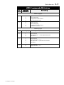
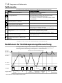
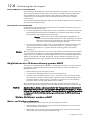
Function Diagrams for Inputs/Outputs
Fault signal /
protection function
Protection mode switching off
Protection mode limiting
in accordance with EASYRIDER config. menu
in accordance with EASYRIDER config. menu
I 2t regulator protection
output Warning(F5) X10.6
output Ready(F0) X10.5
/8/
/3/
/3/
Warning time approx. 3 sec.
I-LIMIT
Warning display
max. current
rated current of regulator
fault signal display
I 2t motor protection
output Warning(F5) X10.6
output Ready(F0) X10.5
/8/
/4/
/4/
Warning time approx. 3 sec.
I-LIMIT
Warning display
max. current
rated current of motor
fault signal display
NTC-motor protection
decrease as of R_NTC1
switch off with R_ NTC2
output Warning(F5) X10.6
output Ready(F0) X10.5
Warning display
/h/
/h/
/9/
I-LIMIT
fault signal display
PTC-motor protection
output Warning(F5) X10.6
/9/
switch off with R_ PTC after warning time
output Ready(F0) X10.5
Warning display
current limiting
no limiting function with PTC
/h/
/9/
fault signal display
Warning time approx. 6 sec.
Function Passive -Delay (recommended for motor brake use)
input ACTIVE OK (F0) X10.7
Nsoll Nsetpoint
setpoint internally to zero
output stage Active
output ACTIVE OK (F4) X10.5 (holding brake)
631 Digital Servo Drive
reaction time for brake
4-6
Operating Modes
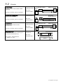
Motor Overload Protection
This may be detected in two ways:
Using Temperature Sensors
These are located in the motor windings. Enter the relevant data (type, tripping value) in to the
EASYRIDER menu: COMMISSIONING / MOTOR / TEMPERATURE SENSOR.
Internal Overload Protection
Using thermal simulation of the motor in the drive (I²t), related to the rated current of the motor.
Enter the rated current of the motor into the EASYRIDER menu: COMMISSIONING /
MOTOR / RATED CURRENT MOTOR.
631 Digital Servo Drive
Initial Set-up
5-1
INITIAL SET-UP
5
Connecting the X15/RS232 EASYRIDER Set-up Service Connect your PC to the 631 Servo Drive using the supplied RS232 cable. The cable is wired as
shown below.
Refer to Chapter 9: “Accessories”.
X15 RS232
4-pole Modular Jack
1
4
Pin
Function
RXD
TXD
for PC RS232
Female
(viewed on
solder side)
1
6
7
GND
8
9
RXD
TXD
1
2
3
4
GND
Receive serial sata
Transmit serial data
3
2
RXD
TXD
5
GND
2
3
4
5
do not connect
GND
IMPORTANT: The X15 interface is not opto-isolated. Connection and disconnection of the
communication cable is only allowed if there is no communication, i.e. PC EASYRIDER on main screen or off-line.
The line-connection of the PC must be close to the servo drive to achieve operation related to a
common reference (common ground).
Make sure that the Functional Earth terminal on the top of the drive is connected to earth.
631 Digital Servo Drive
5-2
Initial Set-up
Pre-Operation Checks
WARNING!
Wait for 5 minutes after disconnecting power before working on any part of the
system or removing the terminal cover from the Servo Drive.
Initial checks before applying power:
• Mains power supply voltage is correct.
• Motor is of correct voltage rating and is connected with the correct polarity.
• Check all external wiring circuits - power, control, resolver, motor and earth connections.
Note: Completely disconnect the Servo Drive before point to point checking with a buzzer, or
when checking insulation with a Meggar.
• Check for damage to equipment.
• Check for loose ends, clippings, drilling swarf etc. lodged in the Servo Drive and system.
• If possible check that the motor can be turned freely, and that any cooling fans are intact and
free from obstruction.
Ensure the safety of the complete system before the Servo Drive is
energised:
• Ensure that rotation of the motor in either direction will not cause damage.
• Ensure that nobody else is working on another part of the system which will be affected by
powering up.
• Ensure that other equipment will not be adversely affected by powering up.
Prepare to energise the Servo Drive and system as follows:
• Remove the supply fuses, or isolate using the supply circuit breaker.
• Disconnect the load from the motor shaft, if possible.
• Check external run contacts are open.
• Check external speed setpoints are all zero.
631 Digital Servo Drive
Initial Set-up
5-3
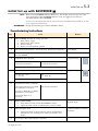
Initial Set-up with EASYRIDER Note: Refer to your EASYRIDER software HELP menu. This chapter presumes you now have
some experience of the EASYRIDER software. If not, we suggest you practice in
Simulation Mode within EASYRIDER.
Access to several software functions is password restricted. Commissioning should be carried
out by competent personnel only.
IMPORTANT: During commissioning, the motor shaft WILL rotate!
Commissioning Instructions
Step
Action
1
Before switching on check the wiring, especially:
• Filter polarity, supply
• Motor wiring, motor polarity
• Resolver wiring,
• Polarity (or other feedback systems)
2
With critical mechanical parts: remove the motor shaft from the application
3
Connect a PC using the RS232 link to the drive service port COM1/X15.
Start EASYRIDER ®.
4
Set up state: NOT ACTIVE
635/ 637/ 637+/ 637f 1)
Connect X10.22 to X10.9
Remark
Avoid danger
7 segment dispay
631
Connect X10.7 to X10.4
POWER ON
5
Switch on the control voltage
635/ 637/ 637+/ 637f
Us = 24V DC
7 segment dispay
631
Us = 230V AC
EASYRIDER® communicates (see diagnosis F9)
6
Are parameters already evaluated?
Yes: load parameter-file xxx.WDD.
Store parameters in the drive.
No: continue with Step 7
If you have a BIAS-file xxx.WBD,
load and store it in the drive.
Proceed with Steps 10 or
16(experts)
7
Menu: Commissioning
•
•
8
When leaving the menu:
•
9
Select the motor used from the EASYRIDER® Library
Adjust maximum current to nominal motor current or smaller
Tuning parameters for the current loop will be calculated and
offered to the user. Normally, these values give dynamic servo
motion.
Store to Power Down Save Memory in the drive.
631 Digital Servo Drive
Reduced torque
Confirm acceptance of offered
parameters
5-4
Initial Set-up
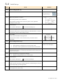
Step
Action
10
Menu: Tuning Speed Loop
11
“ACTIVE” switched on.
Remark
7 segment dispay
12
Adjust test generator as required.
Activate test generator with “START F8”.
Activate graph to display motor current or speed. Can be optimized
manually (P- and I- gain)
13
Is the result ok?
Yes: continue with Step 14
14
No: continue with Step U1.1
Commissioning the Position Controller
Commission the position controller without any linked mechanics. Connect
the mechanics when it is functioning correctly.
15
Power OFF.
Connect the motor shaft to the application.
Rotate the motor shaft to a free area between any mechanical limits.
Power ON.
16
Menu: Tuning Position Loop
17
Adjust test generator:
•
Select Position 1 and Position 2 to a non-critical value.
•
First select a slow speed and low acceleration first. Increase later.
18
“ACTIVE” switched on. Every activation of “START F8” produces a
movement from Position 1 to Position 2; and with the next activation, from
Position 2 to Position 1.
19
Observe the behaviour of application and graph.
•
20
Optimize tuning-parameters (P-, I- and V gain)
Is the result ok?
Yes: continue with Step 21
22
Beware: you may need to stop
the drive in an emergency.
No: continue with Step 9
Basic power-up is now complete.
Further functions (interfaces, fieldbus functions, synchronizing etc.) may be
required depending upon the application.
22
Select the menu “File” store parameters” and store the data in the regulator,
protect against lost, with F7-key
Save data
631 Digital Servo Drive
Initial Set-up
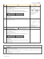
Step
U1.1
Action
5-5
Remark
Menu: Tuning Speed Loop
Stable parameters are calculated based on the system data; and can be called
up with “Default value”.
Sometimes it is recommended to make further manual tuning.
Rated value can be changed either digitally by the internal generator or
analogue by:
635/ 637/ 637+/ 637f
631
P- gain too high or I-time
constant too small
+/- 10V at X10.5/18
+/- 10V at X10.1/2
Motor noise
ATTENTION!
Too hard tuning will cause current ripple and high power dissipation.
U1.2
Too weak adjustment cause slow loop reactions that may cause problems for
the tuning of position loops.
P- gain too small or I-time
constant too high
U1.3
It the result ok?
Yes: continue with Step 9
U2.1
No: continue with Step U2.1
Menu: Tuning Current Loop
Stable parameters are calculated based on the system data and can be called
up with “default value”
Manual tuning may be useful.
Rated value can be changed either digitally by the internal generator or
analogue by:
635/ 637/ 637+/ 637f
631
+/- 10V at X10.5/18
+/- 10V at X10.1/2
ATTENTION!
Tuning of current loops should be only done after consultation of Parker
SSD Drives experts.
Continue with Step 9.
Tuning the Current Loop
IMPORTANT: Only undertake tuning the current loop after consulting with Parker SSD Drives engineers.
U2
Stable parameters are calculated based on the system data and can be called up using the F5 key.
Manual tuning may be necessary.
Rated values can be sourced either digitally by the internal generator or analog by using ±10V at X10.1
and X10.2.
The addition of both sources will be active
Go back to Step 4
631 Digital Servo Drive
5-6
Initial Set-up
631 Digital Servo Drive
Programming Your Application
6-1
PROGRAMMING YOUR APPLICATION
6
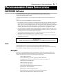
EASYRIDER Software
The EASYRIDER software tool is provided to fine-tune the 631 servo drive to the motor, and
program the servo drive for operation using either “Position Blocks” or the BIAS programming
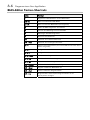
language.
Install the software which is available as a DOS version, or suitable for use as a Windows
application. You can either connect the drive to your PC or you can have the software simulate a
drive. We suggest you practice using a simulation before attempting a set-up for the first time.
When running the software you should be aware of the following:
• The software is password protected. It will initialise with an authorisation of Level 0 (if an
incorrect password is entered it will default to Level 0). At this level you can view the
software without making permanent changes. To configure the drive, you must enter EASY
when asked for the password by Autopilot. This will increase the authorisation to Level 1
allowing you to write permanent changes to the drive. (You can also enter this in the menu:
“Options/Password”).
• There are several demonstrations loaded with the software. To simulate communication with
the 631 product you may need to set this under the following menu: “Options/General
Options/Simulated Drive Type”. This selection is saved when you exit the software.
• You must supply an external 24V supply for terminal X10.7 (ACTIVE/NOT ACTIVE) in
order to operate the drive.
• The software checks for the correct connections to the drive, i.e. resolver, when not
simulating and may not let you proceed with the configuration. Ensure the 631 is fully and
correctly wired.
WARNING!
The EASYRIDER set-up procedure will rotate the motor shaft.
Help
A context-sensitive On-line Help menu is available by pressing the F1 key.
Pressing F9 from any screen displays the Amplifier Diagnosis page from the “Diagnosis” menu
which also contains other helpful pages for fault finding.
Autopilot
Starting the EASYRIDER software displays an option window for running the Autopilot
`wizard’. This is used for initially setting-up the drive and will help you to do the following:
Select the COM port
Select the motor type from a default library, or create your own library
EASYRIDER automatically saves the settings to the drive
Optimise the Speed Loop
Optimise the Position Loop
Select the Operating Mode from the General Configuration page (defaults to Speed
Control)
Select the correct Input/Output functions
Set-up the Counter Configuration page
Set-up the Supervision Configuration page
Set-up any other information necessary to your Operating Mode
Select to save your changes to the drive
631 Digital Servo Drive
6-2
Programming Your Application
Included with these pages are instructions on wiring, safety etc. The Speed Loop and
Position Loop Optimisation pages will already contain sensible values (loaded from
your motor selection) and should require only fine tuning to your system.
Having chosen an Operating Mode, you then make relevant selections in the
Input/Output Configuration page. Press the F1 key for context sensitive help about
each input/output.
The Autopilot instructions recommend that the initial set-up is carried out without load. When
the set-up is complete and load is applied, you can optimise the drive’s performance in the
“Tuning” menu.
Note: Data edited in the EASYRIDER software is transmitted to servo drive but not saved. Only
the command STORE ALL DATA (menu COMMAND/STORE ALL DATA) writes the data
into the servo drive’s non-volatile memory. Data stored here is saved during powerdown.
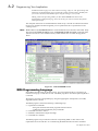
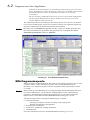
Figure 6-1 An EASYRIDER Screen
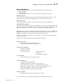
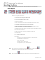
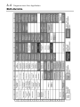
BIAS Programming Language
Select BIAS from the menu in the main screen. You can program the drive to perform a set
routine involving up to 1500 lines of code. The BIAS program is used when Operating Mode 5
is selected.
We suggest you practice programming by using and applying the example files (xxx.ASB)
supplied with the software.
The BIAS program contains the following command groups:
• Organisation commands
- fixing start and end of the main programs and sub-routines
- conditional and unconditional jump commands
• Commands relevant to motion
• Set/delete commands for outputs and flags
• Commands for variables
The BIAS program can provide a PLC function in Operating Mode 5. This removes the
requirement for an external PLC. It is started using the BIAS Execution Pointer command.
631 Digital Servo Drive
Programming Your Application
6-3
Operating Mode 5
Three user-defined programs can be executed in parallel when in Operating Mode 5:
1. The BIAS program
2. The PLC program
3. The Mathematics program (cyclic execution using remaining processing time)
The BIAS program
This is primarily intended for supervising travel commands. If the application permits, simple
calculations can be performed and analog/digital I/O‘s can be serviced in this task.
The PLC program
This performs I/O logic, sequence control, monitoring and CAN-Bus communications.
The Mathematics program
This is deals with complex calculations, e.g. computing of a cam, which is then executed by the
BIAS program. But it is also possible to store the same tasks here, basically defined for PLC task,
which can increase PLC performance of the 630 controllers approximately twenty times.
Whilst the BIAS program is executed from the start block directly after activation of Operating
Mode 5, the PLC program is first started by the BIAS command "PLC-program", and the
Mathematics program is started by the command "Mathematics program".
When the command "End of program" is reached (Mode = 0), the respective execution pointer
jumps to its start label.
The following command groups are provided within the command set:
Program flow control
- Fixing start/end of main and sub-programs
- Conditional and unconditional jump commands
Travel relevant commands
- Positioning commands
- Parameter commands
- Technology functions
>Register positioning
>PID control
>Synchronous applications
Logic commands
- Logic commands for coils and internal relays
Variable commands
- Writing and reading of parameters
- Fundamental operations of arithmetic with long integer
- Type conversions long integer <=> double float (Math task only)
- Fundamental operations of arithmetic with double float (Math task only)
- SIN(x),COS(x),SQRT(x) with double float (Math task only)
- Writing and reading of synchronous profile tables.
CANbus commands
- Communication with other Parker SSD Drives products
For more information refer to the BIAS Programming Language manual (UL,10,6,5).
631 Digital Servo Drive
compare BIAS-program
calculate cam-profile
read BIAS-program
load BIAS-example copy
print BIAS-program paste
delete
search
Exit BIAS-Editor
ins.comment
insert label
go to
BIAS-program definition configuration
transmit BIAS-program
save BIAS-program cut
BIAS-program definitions
program
load BIAS-program redo
edit
change edit mode
file
special function
Editor
BIAS
serial single command
select axis number
store all data
PC-logout
PC-login
reset drive fault
activate drive
deactivate drive
command
diagnosis
field bus diagnosis
oscilloscope
BIAS diagnosis
in-/ output diagnosis
amplifier diagnosis
diagnosis
field bus diagnosis
oscilloscope
BIAS diagnosis
in-/ output diagnosis
amplifier diagnosis
Menu system BIAS-screen
select axis number
serial single command
field bus
PC-logout
store all data
analogue in-/ output
PC-login
reset drive fault
activate drive
deactivate drive
command
position blocks
supervision
position loop
new BIAS-program undo
exit
counter
current loop
speed loop
autopilot
tuning
print parameter motor
general
commissioning
save parameter in-/ output
load parameter
file
update firmware
change password
password/ authorisation level
general options
test serial interface
deutsch / français
select interface
simulate communication
options
update firmware
change password
password/ authorisation level
general options
test serial interface
deutsch / français
select interface
simulate communication
options
6-4
Programming Your Application
EASYRIDER Main Screen - Menu Options
631 Digital Servo Drive
Programming Your Application
Parker SSD Programming Language BIAS
You can program in BIAS using the following set of commands:
Available program area
Set number
0000 ...
|
...
| can be selected via
...
| data inputs X10.xx
...
| maximum to block no. 63
...
| and Strobe X10.8
...
|
0063 ...
...
1499 last block
The BIAS operation set is listed on the next page.
You can read the exact function of the individual commands in the help function of the
EASYRIDER® Windows software in the BIAS editor or in the BIAS command
description (UL:10.06.05).
631 Digital Servo Drive
6-5
6-6
Programming Your Application
BIAS Commands
631 Digital Servo Drive
Programming Your Application
6-7
General Keyboard Definitions
ESC
Alt
Tab
Shift+Tab
Key
F1
F2
F3
F4
F5
F6
F7
F8
F9
F10
F11
=
=
=
=
terminate command
activate menu system
next parameter
previous parameter
Function
online help
PC login
save all data
menu dependant function
diagnosis
deactivate Servo Drive
select active axis
Key
shift+F1
shift+F2
shift+F3
shift+F4
shift+F5
shift+F6
shift+F7
shift+F8
shift+F9
shift+F10
shift+F11
Function
online help
PC logout
menu dependant function
oscilloscope
activate Servo Drive
BIAS Editor Keyboard Shortcuts
631 Digital Servo Drive
Key
Function
F1
General help screen for the BIAS Editor
Shift+F1
Help with the selected BIAS command
Ctrl+F1
Help with the actual BIAS block in program
F2
Load a BIAS program from disk
F3
Save the BIAS program to disk
F4
Transmit the BIAS program
Alt
Activate the menu line
Tab
Change to the next parameter
Shift + Tab
Change to the previous parameter
Ctrl + I
Changing the insert mode (the active mode is displayed at the
bottom of the screen)
Ctrl + L
Inserting a label
Ctrl + K
Inserting a comment line
Ctrl + Cursor
Marking BIAS blocks in the program
Ctrl + Del
Cutting-out marked BIAS blocks
Ctrl + Ins
Copying marked BIAS blocks
Shift + Cursor
Selecting the BIAS command to insert
Shift + Enter
Inserting the selected BIAS command
Shift + Del
Deleting marked BIAS blocks
Shift + Ins
Inserting BIAS blocks which are cut out or copied at the cursor
position
6-8
Programming Your Application
Diagnostics
7 Segment Display
Many faults can be corrected by using the diagnostic display.
display
explanation
comment
no display
servo drive
output
warning2)
631
635/637
637+
637f
off
off
;
;
;
;
off
off
;
;
;
;
;
;
;
;
ready
any control voltage? external fuses ok?
system ready to operate
drive ready, not active
drive ready to operate!
DC link voltage within the limits,
power stage active, fault-free
off
off
;
;
;
;
off
off
;
;
;
;
;
;
;
;
deactivated via input
on
off
deactivated via serial command.
off
off
Active input is activated with switching on
24V control voltage
off
off
;
;
;
;
X10.7
X10.22
X10.22
X10.22
internal STOP with serial deactivating
activate drive via serial interface
regulator of serial interface (bus interface) deactivated !
only if bus interface is integrated
deactivated with delay time for the brake
switch enable X10.xx switch on 0V and
after that 24V
off
off
;
;
;
Under voltage in DC-bus < Ua low threshold
off
off
;
;
;
;
check power supply (power supply unit, wiring, fuse),
check under voltage parameter
feedback system error (e.g. resolver)
off
off
;
;
;
;
1)
1)
;
;
;
;
Under voltage of control voltage
Power supply switched on? Power supply o.k ?
internal fuse o.k.? control voltage < 17 V
wiring to encoder system ok?
encoder system supply ok?
I²t- overload of the drive
does the control loop oscillate?
P-amplification too high, mechanics stiff?
requirements too high? is warning /8/ evaluated?
1) Reaction to these errors chapter: Function diagrams from inputs and outputs
2) With configuration corresponding chapter : Operating modes and pin functions
3) Only warning respect. status indicator
The error signals are shown as long as there is control voltage (Us), also when the power (DC-Bus) is switched off for
safety reasons.
631 Digital Servo Drive
Programming Your Application
play
dis explanation
comment
overload of the motor I²t
does the control loop oscillate?
P-amplification too high mechanics stiff?
requirements too high? is warning /8/ evaluated?
over temperature of the output stage (> 95°C)
adequate cooling of the regulator?
ambient temperature too high?
over voltage on DC bus
6-9
servo drive
output
warning2)
631
635/637
637+
637f
1)
1)
;
;
;
;
1)
1)
;
;
;
;
1)
1)
;
;
;
;
off
off
;
;
;
;
on
1)
;
;
;
;
;
;
;
;
;
;
;
;
;
;
;
;
;
;
;
;
;
;
;
;
ready
ballast module ok? adequate ballast module?
chassis shorting and short circuit due to hardware
motor cabling ok? digital-loops setup ok?
short circuit to chassis in the motor? braking resistor:
ohm- value too low? try to start fresh! send in for
repair
WARNING!
Overload of the regulator I²t or motor I²t or temp.output stage too high. If no reaction within approx.
3sec.it switches off with signals /3/, /4/ or /5/. Signal
/8/ clears when there is no more danger or it is
switched off
mechanics stiff? defective bearings; cold grease?
reduce requirements and creep to next possible STOP
over temperature motor(NTC/PTC)
off
check overload of the motor / cooling etc.
motor temperature too high
on
1)
check overload of the motor / cooling etc.
ballast active
Brake energy is removed
warning I²t ballast too high
ballast resistance usage >90%
switch off ballast
on
1)
ballast resistance overloaded
1)
Reaction to these errors chapter: Function diagrams from inputs and outputs
With configuration corresponding chapter : Operating modes and pin functions
3) Only warning respect. status indicator
The error signals are shown as long as there is control voltage (Us), also when the power (DC-Bus)
is switched off for safety reasons.
2)
631 Digital Servo Drive
6-10
display
Programming Your Application
explanation
comment
X 300 – Module not inserted
or wrong inserted or defect
servo drive
output
ready
off
warning2)
631
635/637
637+
637f
off
;
;
;
;
;
;
;
;
;
;
;
;
;
;
;
;
X10.8
X10.14
X10.14
X10.14
;
;
;
;
X 300 testing
X 300 – setting wrong
3)
X 30 / X40 Counter-Configuration test in
the EASYRIDER® Windows – Software
tracking window exceeded
only in operation mode position control, will be
deleted with the next run-command
tracking error with switch off
only in operation mode "position control"
3)
limit switch +
limit switch + X10.xx on 0 Volt,
from Firmware 6.16
3)
limit switch -
X10.9
X10.15
X10.15
X10.15
3)
limit switch - X10.xx on 0 Volt,
from Firmware 6.16
limit switch + / limit switch -
;
;
;
;
both limit switch X10.xx on 0 Volt,
from Firmware 6.16
memory-checksum-error
X10.8
X10.9
X10.14
X10.15
X10.14
X10.15
X10.14
X10.15
;
;
;
;
;
;
;
;
;
;
off
off
try new start, store the value again
DC Bus Unterspannung < 100 V
1: internal software error, Watchdog
2: blinking: BIAS software error
1: Firmware version check
2: Bias program error fix
1)
Reaction to these errors chapter: Function diagrams from inputs and outputs
With configuration corresponding chapter : Operating modes and pin functions
3) Only warning respect. status indicator
The error signals are shown as long as there is control voltage (Us), also when the power (DC-Bus)
is switched off for safety reasons.
2)
631 Digital Servo Drive
Programming Your Application
display
comment
servo drive
output
explanation
ready
6-11
warning2)
starting lockout RP SBT
631
635/637
637+
637f
;
;
;
;
terminal X290. 3/4 check
Max. speed overload
check speed limits resp. setpoint speed
CAN - Open 402 Sync Message error in Interpolated
positioning mode
6.19c
-
1)
Reaction to these errors chapter: Function diagrams from inputs and outputs
2)
With configuration corresponding chapter : Operating modes and pin functions
3)
Only warning respect. status indicator
The error signals are shown as long as there is control voltage (Us), also when the power (DC-Bus)
is switched off for safety reasons.
631 Digital Servo Drive
8.19d
6-12
Programming Your Application
Resetting the Drive
Note:
Before attempting to reset the drive, the cause of the fault must be eliminated.
Error Signals
at
blinking
(BIAS)
The drive's error signals can be reset via:
1. Switch the Control voltage OFF and then ON.
2. The serial command “Drive Reset“ 0x02
The host must be logged in.
The drive must be deactivated via the serial command “deactivate Drive“ 0x00.
3. The fieldbus command “Drive Reset“ 0x16 (22 decimal)
The host must be logged in via the BUS command 0x01.
The drive must be deactivated via the BUS command “deactivate Drive“ 0x14.
The fieldbus command “Drive Reset“ with constant repetition of the fieldbus command
0x16 will be works-off only once.
For further processing, it is necessary to send another control word
(e.g. 0 status order).
4. a 0 – 1 flank on input X10.10
Precondition:
The input X10.10 is configured with function 1“Reset drive fault“
(EASYRIDER® Windows Software)
There is no host login.
The input "Active" is inactive (0V)
The signal must be present, minimum 250ms
Note:
After removal of the tracking error deactivation
, the warning message
(tracking error) is active until the next move command is issued.
Note:
The error signal
(Active before ready) can be reset by deactivating the drive.
631 Digital Servo Drive
Programming Your Application
6-13
Trouble Shooting
The following list refers to faults which can occur during operation.
Display:
Error
Explanation and remedy
no motor run despite current flow
motor mechanically blocked?
motor brake released?
motor runs unevenly
check setpoint wiring
check grounding and shielding
too high P-amplification in the speed controller reduce
value
(with EASYRIDER® setting/speed control)
too small I-time in the speed controller?
reduce value
(with EASYRIDER® setting/speed control)
no reaction of setpoint progression, despite torque in Limit switch functions
standstill
effective (BIAS)
no current flow;
motor cables interrupted?
no torque despite activating the regulator correctly
Is input "I extern" (X10.19) activated
(config. menu) and not notched up?
1)
1)
limit switch - input
activated and not notched up?
Interference symptoms with power frequency
Ground loops in setpoint or actual value wiring?
Shieldings laid on both sides?
Signal cables near high voltage cables?
Motor takes up preferred positions after activation
Position encoder or motor cables with reversed poles?
Resolver or Feedback- encoder incorrectly adjusted?
Number of motor poles wrong matching?
(config. menu)
Motor runs up immediately after activation although Motor cables or feedback- cables reversed?
there is no setpoint
Encoder incorrectly adjusted?
(e.g. Resolver)
Motor reaches in idling cycle very different speed
Feedback-Encoder incorrectly adjusted
when running to the right or to the left
(e.g. Resolver)
1) Not 631 drive
2) Display
631 Digital Servo Drive
order
mostly short after activating; before warning
2)
2)
6-14
Programming Your Application
631 Digital Servo Drive
Diagnostics and Fault Finding
7-1
DIAGNOSTICS AND FAULT FINDING
7
The seven-segment display is
illuminated when the servo drive is
powered-up. It provides information on
the state of the drive, active trips, and
assists in fault finding.
Remember to remove the protective
film covering the display when
installing the drive.
X
2
0
Diagnostic
Display
X
2
1
X
4
0
X3 0
X
4
1
X15 /RS232
Figure 7-1 Diagnostic Display
Resetting a Trip Condition
There are two options:
1. Switch the supply voltage OFF and ON
2. Use EASYRIDER Trip Diagnostics
Display
Explanation
Ready *
Warning *
(output X10.5) (output
X10.6)
Comment
no display
off
off
Is the supply voltage present?
Are the external fuses ok?
system ready to operate
on
off
regulator ready
not active
system active
output stage active, no interference
internal stop
off
deactivation via serial interface
off
• Re-start the drive
or perform a RESET and activate
the drive
Internal stop
-
-
Deactivation via BIAS command
Active input is activated with
switching on
off
off
• Switch ACTIVE X10.7
to Low and then to High
631 Digital Servo Drive
7-2
Display
Diagnostics and Fault Finding
Explanation
Ready *
Warning *
(output X10.5) (output
X10.6)
Comment
Supply undervoltage
off
off
Is the power supply present?
Status signal disappears, if DC-bus
voltage over the threshold.
Fault Supply undervoltage
off
off
Is the power supply present?
Error signal appears, if DC-bus voltage
under the Ua low threshold.
Fault in resolver system
off
off
Is the encoder system supply present?
Is the wiring to the encoder system
ok?
Is the encoder system ok?
I²t overload of the drive
-
-
Does the control loop oscillate?
P-amplification too high
<Ua low threshold
<Ua low threshold
Mechanics stiff?
Requirements too high?
Is warning /8/ evaluated?
overload of the motor I²t
-
-
Does the control loop oscillate?
P-amplification too high
Mechanics stiff?
Requirements too high?
Is warning /8/ evaluated?
overtemperature of the output
stage
-
-
Adequate cooling of the regulator?
Is the ambient temperature too high?
overvoltage DC bus
-
-
Ballast module ok?
Adequate ballast module?
Chassis shorting and short
circuit due to hardware
off
off
Is the motor cabling ok?
Are the digital loops setup ok?
Is there a short circuit to chassis in
the motor?
Is the braking resistor Ohm value too
low?
• Apply a toroidal core or choke in
motor-cable.
• Try to restart
• Return the unit for repair
WARNING!
Overload of the regulator or
motor.
If no reaction within
approximately 3 seconds the unit
switches off with signals /3/, /4/
or /5/.
Signal /8/ clears when there is no
more danger or the unit is
switched off
on
*
Mechanics stiff?
Defective bearings;
Cold grease?
• Reduce requirements and creep to
next possible STOP
631 Digital Servo Drive
Diagnostics and Fault Finding
Display
7-3
Explanation
Ready *
Warning *
(output X10.5) (output
X10.6)
Comment
overtemperature motor
off
Check overload of the motor/cooling
etc.
motor temperature warning
on
(NTC/PTC)
*
ballast active
Check overload of the motor/cooling
etc.
Brake energy is removed
warning ballast
on
*
Ballast resistance usage is >90%
switch off ballast
on
*
Ballast resistance overloaded
trailing window exceeded
Only in operation mode "position
control"
• optimise parameters
• check mechanics
trailing error with switch off
Only in operation mode "position
control"
• optimise parameters
• check mechanics
• increase trailing window
memory checksum error
off
off
• Try to restart
• Load new parameters
internal fault
off
off
• controller fault
Return the unit for repair
* Configuration as stated, refer to Chapter 4:“Operating Modes” - Configuring the OPTO
Inputs and Outputs (X10)
The last error signal will be displayed after restart in EASYRIDER - Diagnosis:Menu,
(History Status Memory, page 7-5).
631 Digital Servo Drive
7-4
Diagnostics and Fault Finding
Fault Finding
The following list refers to faults which can occur during operation.
Error
Explanation and remedy
Motor does not operate despite current flow
Is the motor mechanically blocked?
Is the motor brake released?
Motor runs unevenly
Check the setpoint wiring. Check grounding and shielding.
Inappropriate speed loop values ?
• Reduce amplification and/or increase time constant (use
EASYRIDER)
No reaction on setpoint value although
torque in stand still
Limit switch - functions activated ? (BIAS)
No current flow; no torque despite activating
the regulator correctly
Motor cables interrupted?
Interference symptoms with power frequency
Ground loops in setpoint or actual value wiring?
Shieldings laid on both sides?
Signal cables near high voltage cables?
*
Motor takes up preferred positions after
activation
Position encoder or motor cables with reversed poles?
Resolver or encoder incorrectly adjusted?
Number of motor poles set incorrectly? (config. menu)
*
Motor runs up immediately after activation
although there is no setpoint
Motor cables or resolver cables reversed?
Resolver incorrectly adjusted?
*
Motor reaches, in idling cycle, a very different Resolver incorrectly adjusted
speed when running right from running left
* Displays /3./ or /4./ for a short time after activating before showing warning /8./
631 Digital Servo Drive
Diagnostics and Fault Finding
7-5
Re-actions of Supply Voltage Supervising Functions
The following diagram refers to the internal dc bus voltage (rectified from an ac voltage). Note
that voltage ripple effects have to be taken in to account, refer to Chapter 11: “Technical
Specifications” - Derating of Output Voltage.
Variations of internal DC Bus Voltage
DC 400 V
DC 380 V
DC 373 V
Nominal Area
DC 280 V
DC 100 V*
approximately
DC 60V
t
Display
Drive Status
Precharge
2 seconds
ok
Fail
Low Voltage
Reset by ok Dynamic
power down
Braking
ok
Fail
High voltage
* Default value, may be changed using EASYRIDER
History Status Memory
When the unit is powered down, a set of important indicators is stored in to dedicated memory.
This allows the last eight status conditions to displayed by the EASYRIDER diagnostic
menu Thus important failure information, for instance, is not lost when the unit is powered
down.
631 Digital Servo Drive
7-6
Diagnostics and Fault Finding
631 Digital Servo Drive
Routine Maintenance and Repair
8-1
ROUTINE MAINTENANCE AND REPAIR
8
Routine Maintenance
Periodically inspect the Servo drive for build-up of dust or obstructions that may affect
ventilation of the unit. Remove this using dry air.
Repair
There are no user-serviceable components.
IMPORTANT: MAKE NO ATTEMPT TO REPAIR THE UNIT - RETURN IT TO PARKER SSD DRIVES.
Saving Your Application Data
Although the Servo drive retains saved settings during power-down, it would be wise for you to
keep a back-up of your data. You may, depending upon your knowledge of the fault, attempt the
back-up of your application data now.
Returning the Unit to Parker SSD Drives
Please have the following information available:
•
•
The model and serial number - see the unit’s rating label
Details of the fault
Contact your nearest Parker SSD Drives Service Centre to arrange return of the item.
You will be given a Returned Material Authorisation. Use this as a reference on all paperwork
you return with the faulty item. Pack and despatch the item in the original packing materials; or
at least an anti-static enclosure. Do not allow packaging chips to enter the unit.
Disposal
The digital servo drive consists of different materials.
The following table shows, which materials can be recycled and which have to be disposed of in
a special way.
Material
Recycle
Disposal
metal
yes
no
plastics material
yes
no
printed board assembly
no
yes
IMPORTANT: Dispose of the appropriate materials in accordance with the valid environmental control
laws.
631 Digital Servo Drive
8-2
Routine Maintenance and Repair
631 Digital Servo Drive
Accessories
9-1
ACCESSORIES
9
Note: Other cable lengths are available, contact Parker SSD Drives for details.
Products
Motor Cable
For ACG motors only
Low-cost cable for fixed installations only
- without Holding Brake wires
Motor Cable
For ACG, AC M2n and AC Rn motors
Flexible cable - with holding brake wires
Resolver Cable
For ACG, AC M2n and AC Rn motors
(X30)
Low-cost cable for fixed installations only
Resolver Cable
For ACG, AC M2n and AC Rn motors
(X30)
Flexible cable
RS232 Service Connector Cable
X15 (631 to PC)
Jumper for Peer-to-Peer Units
X20/21 (CAN-Bus)
X40/41 (Multi-function)
unshielded flat cable
BUS Termination Plug
X20/21 (CAN-Bus)
Cable for Host Units
X20/21 (CAN-Bus)
2 twisted pairs, shielded cable
unterminated at free-end
Adaptor Cable
631 X20/21 to 635/637/IBT COM2
(CAN-Bus)
2 twisted pairs, shielded cable
631 Digital Servo Drive
Order Number
Illustration
UK:
CM469021U020
2m
Germany:
MK.1042.0020
UK:
CM469023U020
2m
Germany:
MK.6400.0020
UK:
CM469025U020
Sub-miniature D, 9 way
Germany:
RK.631030020
2m
UK:
CM469027U020
Sub-miniature D, 9 way
Germany:
RK.6300.0020
UK:
LA387599
Germany:
KK.5004.0003
UK:
CM469036U001
2m
RJ11 Plug
Sub-miniature D, 9 way female
3.0m
RJ45 Plug 8 way
Germany:
KK.6310.0001
RJ45 Plug 8 way
100mm
UK:
CI469030
RJ45 Plug 8 way
124Ω
Germany:
ST.0931.0001
UK:
CM469029U010
pairs
Round cable,
2TP, shielded
Germany:
KK.6310.0301
1
1m
UK:
CM469031U003
Germany:
KK.6310.0500
RJ45 Plug 8 way
8
RJ45 Plug 8 way
pairs
1
8
Sub-miniature D, 9 way male
300 mm
9-2
Accessories
Cable for Host Units
X40/41 (Multi-function)
4 twisted pairs, shielded cable
unterminated at the free-end
Adaptor Cable
631 X40/41 to 635/637 X40
(Multi-function)
4 twisted pairs, shielded cable
Brake Resistor
A resistor fitted externally for transient
braking operations
33Ω, 100W - overload capability
approximately 5000%/0.5 seconds
UK:
CM469033U010
pairs
Round cable,
4TP, shielded
Germany:
KK.6310.0401
1
1m
UK:
CM469034U003
Germany:
KK.6310.0600
RJ45 Plug 8 way
8
RJ45 Plug 8 way Sub-miniature D, 9 way female
pairs
300 mm
1
8
UK:
CZ469019
Germany:
ZU.5003.1001
Flying Leads 0.5m
20mm
40mm
165mm
631 Digital Servo Drive
Reference Tables
10-1
REFERENCE TABLES
0
1
ASCII Table
BINARY
b6
b5
0
0
0
b4
0
0
0
0
1
1
1
1
0
1
0
1
1
0
0
1
1
1
1
0
1
b3
b2
b1
b0
HEX
0x
1
2
3
4
5
6
7
0
0
0
0
x0
NUL
DLE
SP
0
@
P
`
p
0
0
0
1
1
SOH
DC1
!
1
A
Q
a
q
0
0
1
0
2
STX
DC2
“
2
B
R
b
r
0
0
1
1
3
ETX
DC3
#
3
C
S
c
s
0
1
0
0
4
EOT
DC4
$
4
D
T
d
t
0
1
0
1
5
ENQ
NAK
%
5
E
U
e
u
0
1
1
0
6
ACK
SYN
&
6
F
V
f
v
0
1
1
1
7
BEL
ETB
‘
7
G
W
g
w
1
0
0
0
8
BS
CAN
(
8
H
X
h
x
1
0
0
1
9
HT
EM
)
9
I
Y
i
y
1
0
1
0
A
LF
SUB
*
:
J
Z
j
z
1
0
1
1
B
VT
ESC
+
;
K
[
k
{
1
1
0
0
C
FF
FS
,
<
L
\
l
|
1
1
0
1
D
CR
GS
-
=
M
]
m
}
1
1
1
0
E
SO
RS
.
>
N
^
n
~
1
1
1
1
F
SI
US
/
?
O
_
o
DEL
631 Digital Servo Drive
10-2
Reference Tables
Decimal/Hexadecimal Table
0
10
20
30
40
50
60
70
80
90
100
110
120
130
140
150
160
170
180
190
200
210
220
230
240
250
260
270
280
290
300
310
320
330
340
350
360
370
380
390
400
410
420
430
440
450
460
470
480
490
0
0000
000A
0014
001E
0028
0032
003C
0046
0050
005A
0064
006E
0078
0082
008C
0096
00A0
00AA
00B4
00BE
00C8
00D2
00DC
00E6
00F0
00FA
0104
010E
0118
0122
012C
0136
0140
014A
0154
015E
0168
0172
017C
0186
0190
019A
01A4
01AE
01B8
01C2
01CC
01D6
01E0
01EA
1
0001
000B
0015
001F
0029
0033
003D
0047
0051
005B
0065
006F
0079
0083
008D
0097
00A1
00AB
00B5
00BF
00C9
00D3
00DD
00E7
00F1
00FB
0105
010F
0119
0123
012D
0137
0141
014B
0155
015F
0169
0173
017D
0187
0191
019B
01A5
01AF
01B9
01C3
01CD
01D7
01E1
01EB
2
0002
000C
0016
0020
002A
0034
003E
0048
0052
005C
0066
0070
007A
0084
008E
0098
00A2
00AC
00B6
00C0
00CA
00D4
00DE
00E8
00F2
00FC
0106
0110
011A
0124
012E
0138
0142
014C
0156
0160
016A
0174
017E
0188
0192
019C
01A6
01B0
01BA
01C4
01CE
01D8
01E2
01EC
3
0003
000D
0017
0021
002B
0035
003F
0049
0053
005D
0067
0071
007B
0085
008F
0099
00A3
00AD
00B7
00C1
00CB
00D5
00DF
00E9
00F3
00FD
0107
0111
011B
0125
012F
0139
0143
014D
0157
0161
016B
0175
017F
0189
0193
019D
01A7
01B1
01BB
01C5
01CF
01D9
01E3
01ED
4
0004
000E
0018
0022
002C
0036
0040
004A
0054
005E
0068
0072
007C
0086
0090
009A
00A4
00AE
00B8
00C2
00CC
00D6
00E0
00EA
00F4
00FE
0108
0112
011C
0126
0130
013A
0144
014E
0158
0162
016C
0176
0180
018A
0194
019E
01A8
01B2
01BC
01C6
01D0
01DA
01E4
01EE
5
0005
000F
0019
0023
002D
0037
0041
004B
0055
005F
0069
0073
007D
0087
0091
009B
00A5
00AF
00B9
00C3
00CD
00D7
00E1
00EB
00F5
00FF
0109
0113
011D
0127
0131
013B
0145
014F
0159
0163
016D
0177
0181
018B
0195
019F
01A9
01B3
01BD
01C7
01D1
01DB
01E5
01EF
6
0006
0010
001A
0024
002E
0038
0042
004C
0056
0060
006A
0074
007E
0088
0092
009C
00A6
00B0
00BA
00C4
00CE
00D8
00E2
00EC
00F6
0100
010A
0114
011E
0128
0132
013C
0146
0150
015A
0164
016E
0178
0182
018C
0196
01A0
01AA
01B4
01BE
01C8
01D2
01DC
01E6
01F0
7
0007
0011
001B
0025
002F
0039
0043
004D
0057
0061
006B
0075
007F
0089
0093
009D
00A7
00B1
00BB
00C5
00CF
00D9
00E3
00ED
00F7
0101
010B
0115
011F
0129
0133
013D
0147
0151
015B
0165
016F
0179
0183
018D
0197
01A1
01AB
01B5
01BF
01C9
01D3
01DD
01E7
01F1
8
0008
0012
001C
0026
0030
003A
0044
004E
0058
0062
006C
0076
0080
008A
0094
009E
00A8
00B2
00BC
00C6
00D0
00DA
00E4
00EE
00F8
0102
010C
0116
0120
012A
0134
013E
0148
0152
015C
0166
0170
017A
0184
018E
0198
01A2
01AC
01B6
01C0
01CA
01D4
01DE
01E8
01F2
9
0009
0013
001D
0027
0031
003B
0045
004F
0059
0063
006D
0077
0081
008B
0095
009F
00A9
00B3
00BD
00C7
00D1
00DB
00E5
00EF
00F9
0103
010D
0117
0121
012B
0135
013F
0149
0153
015D
0167
0171
017B
0185
018F
0199
01A3
01AD
01B7
01C1
01CB
01D5
01DF
01E9
01F3
631 Digital Servo Drive
Reference Tables
10-3
Decimal/Hexadecimal Table
500
510
520
530
540
550
560
570
580
590
600
610
620
630
640
650
660
670
680
690
700
710
720
730
740
750
760
770
780
790
800
810
820
830
840
850
860
870
880
890
900
910
920
930
940
950
960
970
980
990
0
01F4
01FE
0208
0212
021C
0226
0230
023A
0244
024E
0258
0262
026C
0276
0280
028A
0294
029E
02A8
02B2
02BC
02C6
02D0
02DA
02E4
02EE
02F8
0302
030C
0316
0320
032A
0334
033E
0348
0352
035C
0366
0370
037A
0384
038E
0398
03A2
03AC
03B6
03C0
03CA
03D4
03DE
631 Digital Servo Drive
1
01F5
01FF
0209
0213
021D
0227
0231
023B
0245
024F
0259
0263
026D
0277
0281
028B
0295
029F
02A9
02B3
02BD
02C7
02D1
02DB
02E5
02EF
02F9
0303
030D
0317
0321
032B
0335
033F
0349
0353
035D
0367
0371
037B
0385
038F
0399
03A3
03AD
03B7
03C1
03CB
03D5
03DF
2
01F6
0200
020A
0214
021E
0228
0232
023C
0246
0250
025A
0264
026E
0278
0282
028C
0296
02A0
02AA
02B4
02BE
02C8
02D2
02DC
02E6
02F0
02FA
0304
030E
0318
0322
032C
0336
0340
034A
0354
035E
0368
0372
037C
0386
0390
039A
03A4
03AE
03B8
03C2
03CC
03D6
03E0
3
01F7
0201
020B
0215
021F
0229
0233
023D
0247
0251
025B
0265
026F
0279
0283
028D
0297
02A1
02AB
02B5
02BF
02C9
02D3
02DD
02E7
02F1
02FB
0305
030F
0319
0323
032D
0337
0341
034B
0355
035F
0369
0373
037D
0387
0391
039B
03A5
03AF
03B9
03C3
03CD
03D7
03E1
4
01F8
0202
020C
0216
0220
022A
0234
023E
0248
0252
025C
0266
0270
027A
0284
028E
0298
02A2
02AC
02B6
02C0
02CA
02D4
02DE
02E8
02F2
02FC
0306
0310
031A
0324
032E
0338
0342
034C
0356
0360
036A
0374
037E
0388
0392
039C
03A6
03B0
03BA
03C4
03CE
03D8
03E2
5
01F9
0203
020D
0217
0221
022B
0235
023F
0249
0253
025D
0267
0271
027B
0285
028F
0299
02A3
02AD
02B7
02C1
02CB
02D5
02DF
02E9
02F3
02FD
0307
0311
031B
0325
032F
0339
0343
034D
0357
0361
036B
0375
037F
0389
0393
039D
03A7
03B1
03BB
03C5
03CF
03D9
03E3
6
01FA
0204
020E
0218
0222
022C
0236
0240
024A
0254
025E
0268
0272
027C
0286
0290
029A
02A4
02AE
02B8
02C2
02CC
02D6
02E0
02EA
02F4
02FE
0308
0312
031C
0326
0330
033A
0344
034E
0358
0362
036C
0376
0380
038A
0394
039E
03A8
03B2
03BC
03C6
03D0
03DA
03E4
7
01FB
0205
020F
0219
0223
022D
0237
0241
024B
0255
025F
0269
0273
027D
0287
0291
029B
02A5
02AF
02B9
02C3
02CD
02D7
02E1
02EB
02F5
02FF
0309
0313
031D
0327
0331
033B
0345
034F
0359
0363
036D
0377
0381
038B
0395
039F
03A9
03B3
03BD
03C7
03D1
03DB
03E5
8
01FC
0206
0210
021A
0224
022E
0238
0242
024C
0256
0260
026A
0274
027E
0288
0292
029C
02A6
02B0
02BA
02C4
02CE
02D8
02E2
02EC
02F6
0300
030A
0314
031E
0328
0332
033C
0346
0350
035A
0364
036E
0378
0382
038C
0396
03A0
03AA
03B4
03BE
03C8
03D2
03DC
03E6
9
01FD
0207
0211
021B
0225
022F
0239
0243
024D
0257
0261
026B
0275
027F
0289
0293
029D
02A7
02B1
02BB
02C5
02CF
02D9
02E3
02ED
02F7
0301
030B
0315
031F
0329
0333
033D
0347
0351
035B
0365
036F
0379
0383
038D
0397
03A1
03AB
03B5
03BF
03C9
03D3
03DD
03E7
10-4
Reference Tables
631 Digital Servo Drive
Technical Specifications
11-1
TECHNICAL SPECIFICATIONS
1
General Data
Environmental Details
The unit MUST be mounted inside a suitable cubicle.
Operating Temperature
0°C to 40°C (derate the output current by 2% per °C between 40-50°C
Operating temperature is defined as the ambient temperature to the immediate surround of the
Servo Drive, when the Servo Drive and other equipment adjacent to it is operating at worst case
conditions.
Storage Temperature
-25°C to +55°C
Shipping Temperature
-25°C to +70 °C
Product Enclosure Rating
Cubicle Mounted
Vibration Test
In accordance with DIN IEC 68-2-6, test FC
Condition for testing:
frequency range : 10...57Hz, 57Hz...150Hz
amplitude : 0.075mm
acceleration : 1g
test time per axis : 10 frequency/sweep cycle
frequency sweep speed : 1 minute
Altitude
If >1000 metres above sea level, derate Motor Power rating by 1% per 100 metres
Humidity
Maximum 85% relative humidity at 40°C non-condensing
Atmosphere
Non flammable, non corrosive and dust free
Climatic Conditions
Class 3k3, as defined by EN50178 (1998)
Safety
Overvoltage Category
Overvoltage Category III
Pollution Degree
Europe
North America/Canada
IP20
Pollution Degree 2
When fitted inside a cubicle this product conforms with the Low Voltage Directive 73/23/EEC
with amendment 93/68/EEC, Article 13 and Annex III using EN50178 (1998) to show
compliance.
Complies with the requirements of UL508C as an open-type drive
Insulation Concept
Insulation Concept
X15 : RS232
X20, X21:
CAN-Bus
Power Terminals
L1, L2/N
X10 : analog
Motor Terminals
M1, M2, M3
X10 : digital
External Brake Resistor Terminals
DBR1, DBR2
X30: Resolver, Motortemp. 1
X40, X41 : multi-function
SELV according to EN 50178 (double isolation)
PE
Extra-low voltage isolation by opto-coupler, for immunity (not safety)
631 Digital Servo Drive
11-2 Technical Specifications
Cabling Requirements for EMC Compliance
* For cable lengths longer than 15 and up to 50 metres contact Parker SSD Drives.
Resolver
Power Supply Cable
Motor Cable
Brake Resistor
Cable
Signal/Control Cable
Screened
Unscreened
Screened/
armoured
Screened
Screened
Segregation
From all
other
wiring
(sensitive)
From all other
wiring (clean)
From all other wiring (noisy)
From all other wiring
(sensitive)
Length Limitations
With Internal AC
Supply EMC Filter
50 metres
Unlimited
15 metres
domestic,
2metres
25 metres
Screen to Earth
Connection
Both ends
Both ends
Both ends
Cable Type
(for EMC
Compliance)
50 metres *
industrial
Both ends
Fuse Rating and Recommended Wire Sizes
Refer to Chapter 9: “Accessories”
Local wiring regulations always take precedence.
* European wire sizes are based on EN60204-1 (1993) for PVC single-core cable bunched or
in trunking given a 70ºC maximum conductor temperature under normal conditions in a 45ºC
ambient.
North American wire sizes are based on NEC/NFPA-70 for ampacities of thermoplasticinsulated (60ºC) copper conductors assuming not more than three current-carrying conductors in
raceway or cable, based on ambient temperature of 30ºC. The wire sizes allow for an ampacity
of 125% of the rated input and output amperes for motor branch-circuit conductors as specified
in NEC/NFPA-70.
Input
Output
631
Input Fuse Rating
Product
Code
* European
Wire Size (45ºC)
North American
Wire Size
(A)
(mm²)
(AWG)
* European Wire
Size (45ºC)
[for reduced cable
power losses]
North American
Wire Size
(AWG)
(mm²)
631/001
10.0
1.0
16
1.5
16
631/002
10.0
1.0
16
1.5
16
631/004
10.0
1.5
12
1.5 [2.5]
16 [14]
631/006
20.0
2.5
12
1.5 [2.5]
16 [14]
Terminal Block Wire Sizes
Wire sizes should be chosen with respect to the operating conditions and your local National
Electrical Safety Installation Requirements.
Power Terminals (X1)
Maximum acceptance for aperture: 12 AWG (3.3mm²)
Control Terminals
(X10)
0.08mm² - 2.1mm² (28 AWG - 14 AWG)
Communication Terminals
(X20 / X21, X40 / X41)
26 AWG
For information:
12 AWG (3.3mm²), 14 AWG (2.5mm²), 18 AWG (0.8mm²), 20 AWG (0.5mm²) 22 AWG (0.3mm²)
631 Digital Servo Drive
Technical Specifications
11-3
Earthing/Safety Details
Refer to Chapter 12 : “Certification for the Servo Drive”.
Earthing
Permanent earthing is mandatory on all units.
•
Use a copper protective earth conductor 10mm² minimum cross-section, or install a second
conductor in parallel with the protective conductor to a separate protective earth terminal
•
The conductor itself must meet local requirements for a protective earth conductor
Input Supply Details
Units with the internal filter are only suitable for use on earth referenced supplies (TN).
(TN) and (IT)
Units without the filter are suitable for earth (TN) or non-earth referenced (IT) supplies.
Power Circuit
Electrical separation from control circuit
In accordance with VDE 0160 / EN 50178 or UL508C
Short-circuit and to frame proof for
≤ 1000 releasings
Overvoltage monitoring DC Bus
Maximum 400V dc ±5V dc
Undervoltage monitoring
100V dc / 70V ac
Overtemperature of Power Stage
Supervised
Carrier frequency
4.75kHz
Frequency of current ripple
9.5kHz
Power losses:
Fan, internal electronic
Power stage per A
15W
9W/A
Control Terminals (X10)
Additional galvanic separation from power and control
circuit
Nominal voltage of the inputs and outputs
24V DC
Number of outputs
Signal outputs via OPTO coupler
2
Umax = 30V DC;
I = 0..60 mA; short circuit proof,
resistive load
Number of inputs
Signal outputs via OPTO coupler
4
L = 0...7 V DC or open
H = 15...30 V DC
Iin 24VDC @ 8 mA
Reaction time of the inputs X10.7, X10.8
> 2 ms
Reaction time of the inputs X10.9, X10.10 (configured
as latch input ”see chapter 3”)
Effect of cycle-time
0,02 ms
10 μs
Also see Chapter 4: “Operating the Servo Drive” - Configuring the I/Os (X10)
631 Digital Servo Drive
11-4 Technical Specifications
Resolver Conversion (X30)
The specified data refers to the standard resolver interface, operated with the Parker SSD Drives
Resolver
R 21-T05, R15-T05.
Carrier frequency
ft = 4.75kHz
Linearity error of the actual value signal 1%
Ripple of the actual value signal
2%
Maximum position resolution for one
revolution
16384 increments, 14 bit
Absolute position accuracy
±0.7°
Relative position accuracy
±0.08°
Digital Communication (X15, X20/X21)
X15 - RS232 (Service Interface)
Standard setting
19200 baud, 8 databits, 1 startbit, 1 stopbit, parity: even
Protocol
See the separate manual
Protocol
See the separate manual
X20 / X21 - CAN-Bus
X40/X41 - Multi-function Input/Output
Plug model
Modular Plug AMP, 8-pole
Internal hardware connection from
X40 to X41
direct wired 1:1 (X40 = X41)
Maximum input or output frequency
200kHz
Maximum cable length connected to
galvanical insulated terminals
(Encoder, controls)
25metres, for extended distances please contact Parker SSD Drives
Maximum cable length connected to
ground related terminals (other drives,
controls)
2 metres (ensure good common grounding)
Maximum number of signal inputs
when configured as an incremental
output device
8
Uutput signals
driver model: Type RS485
differential logic level
Low ≤ 0.5V
nominal range
0.0 ... 5.0V
Input signals
High ≥ 2.5V
receiver model: Type RS422
differential input level
differential minimum = 0.2V
nominal range
0.0 ... 5.0V
Nominal signal difference
1.0V
Controller System
System run-up time after switching on
6s maximum
Data memory / organization
Flash Eprom 256KB
RAM 64KB
EEPROM 512 Byte
631 Digital Servo Drive
Technical Specifications
Digital Control
Current Control
Settings
According to factory specifications or motor data
Current Limits
Set by the Parameter Menu
Speed Control
Settings
Set by the Parameter Menu
Differential Setpoint Input Analog
Usoll = 10V, can be normed; Ri = 10k
Resolution (including sign)
12 bit
Digital Setpoint Input
Via interfaces
631 Digital Servo Drive
11-5
11-6 Technical Specifications
Product Specific Data
IMPORTANT: Motor power, output current and input current must not be exceeded under steady state
operating conditions.
631 Product Code - block 2
001
002
004
006
EMC Compliance
All models
European Community Directive 89/336/EEC
All models
EN50082-1 (1992) and EN50082-2 (1995) for immunity
If fitted with an internal filter
EN50081-1 (1992) and EN50081-2 (1994)
Input
Supply details (note 3)(refer to
Earthing/Safety Details table)
220/240V ±10%, 50/60 Hz, single phase (IT/TN)
Maximum continuous
input current (ln)
Fuse rating (note 2)
3
5,5
9,6
11
10A
10A
10A
20A
Power-on current limit
Soft start: capacitor pre-charge via 330Ω
Line filter
Internal when filter option is supplied.
According to EN50081-1 (1992), residual area,
maximum motor cable length is 15m
Earth leakage current
7.5mA
Supply short-circuit capacity
5000A maximum
Output
Sinewave voltage at Un
210/230
Derating of Unr when loaded
Refer to Chapter 13: “Application Notes”
Rated output current rms
1A
2A
Output overload motoring
Minimum motor inductance
(between terminals)
4A
125% for32s
150% for 18s
175% for 12s
200% for 9s
12.0mH
6.0mH
3.0mH
6A
2.0mH
Brake Circuit
Brake circuit setpoint dc
380V
Internal Brake Resistor
Internal brake resistor
410Ω internal build
Internal brake circuit power
nominal/maximum
8W / 352W internal
External Brake Resistor (DBR1 & DBR2)
Minimum braking resistor external
(note 1)
externally connectable on terminals DBR1, DBR2
Nominal/maximum power external
100W / 4375W external
Notes:
1) Use only Parker SSD Drives approved types
2)
Fuses, medium speed or according to suggestion:
Fuse and item number
10A
CH 430014
20A
CH 430024
Fuse holder 10x38mm
CP051602
3)
Devices with built-in filter may be operated only
in grounded networks (TN-Networks) with
permanently connected protective conductor.
631 Digital Servo Drive
Certification for the Servo Drive
12-1
CERTIFICATION FOR THE SERVO DRIVE
2
1
Requirements for EMC Compliance
All Variable Speed Drives (VSDs) potentially produce electrical emissions which are radiated
into the environment and conducted back into the ac supply. VSDs are inherently immune to
any additional external electrical noise. The following information is provided to maximise the
Electro Magnetic Compatibility (EMC) of VSDs and systems in their intended operating
environment, by minimising their emissions and maximising their immunity.
Minimising Radiated Emissions
EN55011/EN55022 radiated emission measurements are made between 30MHz and 1GHz in
the far field at a distance of 10 to 30 metres. Limits lower than 30MHz or in close proximity are
not specified. Emissions from individual components tend to be additive.
•
Use a screened/armoured cable between VSD/cubicle and motor containing the motor
protective earth (PE) connection. It should have a 360° screen termination. Earth screen at
both ends connecting to the motor frame and cubicle. Maintain the screen integrity using
360° terminations.
Note: Some hazardous area installations may preclude direct earthing at both ends of the
screen, in this case earth one end via a 1μF 50Vac capacitor, and the other as normal.
•
Keep unshielded cable as short as possible inside the cubicle.
•
Always maintain the integrity of the shield.
•
If the cable is interrupted to insert contactors etc., re-connect the screen using the shortest
possible route.
•
Keep the length of screen stripped-back as short as possible when making screen
connections.
•
Ideally use 360° screen terminations using cable glands or `U’ clips on power screen rails.
If a shielded cable is not available, lay unshielded motor cables in a metal conduit which will act
as a shield. The conduit must be continuous with a direct electrical contact to the VSD and
motor housing. If links are necessary, use braid with a minimum cross sectional area of 10mm2.
Note: Some motor gland boxes and conduit glands are made of plastic, if this is the case, then
braid must be connected between the screen and the chassis. In addition at the motor
end, ensure that the screen is electrically connected to the motor frame since some
terminal boxes are insulated from the frame by gasket/paint.
Earthing Requirements
IMPORTANT: Protective earthing always takes precedence over EMC earthing.
Protective Earth (PE) Connections
Note: In accordance with installations to EN60204, only one protective earth conductor is
permitted at each protective earth terminal contacting point.
Local wiring regulations may require the protective earth connection of the motor to be
connected locally, i.e. not as specified in these instructions. This will not cause shielding
problems because of the relatively high RF impedance of the local earth connection.
EMC Earth Connections
For compliance with EMC requirements, we recommend that the “0V/signal ground” is
separately earthed. When a number of units are used in a system, these terminals should be
connected together at a single, local earthing point.
631 Digital Servo Drive
12-2
Certification for the Servo Drive
Control and signal cables for the encoder and all analog inputs normally require screening with
the screen connected only at the VSD end. However, if high frequency noise is still a problem,
earth screen at the non VSD end via a 0.1μF capacitor.
Note: Connect the screen (at the VSD end) to the VSD protective earth point, and not to the
control board terminals.
Cabling Requirements
Note: Refer to Chapter 11: “Technical Specifications” for additional Cabling Requirements.
Planning Cable Runs
•
Use the shortest possible motor cable lengths.
•
Use a single length of cable to a star junction point to feed multiple motors.
•
Keep electrically noisy and sensitive cables apart.
•
Keep electrically noisy and sensitive parallel cable runs to a minimum. Separate parallel
cable runs by at least 0.25 metres. For runs longer than 10 metres, separation should be
increased proportionally. For example if the parallel runs were 50m, then the separation
would be (50/10) x 0.25m = 1.25m.
•
Sensitive cables should cross noisy cables at 90°.
•
Never run sensitive cables close or parallel to the motor and braking chopper circuit for any
distance.
•
Never run supply or motor cables in the same bundle as the signal/control and feedback
cables, even if they are screened.
Increasing Motor Cable Length
Because cable capacitance and hence conducted emissions increase with motor cable length,
conformance to EMC limits is only guaranteed with the internal ac supply filter option.
Screened/armoured cable has significant capacitance between the conductors and screen which
increases linearly with cable length (typically 200pF/m but varies with cable type and current
rating).
Long cable lengths may have the following undesirable effects:
•
Tripping on `overcurrent’ as the cable capacitance is charged and discharged at the
switching frequency.
•
Producing increased conducted emissions which degrade the performance of the EMC filter
due to saturation.
•
Causing RCDs (Residual Current Devices) to trip due to increased high frequency earth
current.
•
Producing increased heating inside the EMC ac supply filter from the increased conducted
emissions.
These effects can be overcome by adding chokes or output filters at the output of the VSD.
EMC Installation Options
The unit, when installed for Class A or Class B operation, will be compliant with EN55011
(1991)/ EN55022 (1994) for radiated emissions, as described below.
Screening & Earthing (wall mounted, Class A)
IMPORTANT: This unit must be mounted inside a suitable control cubicle requiring a tool for opening
to maintain compliance with the European Electrical Safety Standard VDE0160 (1994)
/EN50178 (1998).
The unit is installed for Class A operation when wall mounted inside a cubicle and having
complied with all cabling requirements.
631 Digital Servo Drive
Certification for the Servo Drive
12-3
Note: The installation requirements of local safety standards must be achieved regarding the
safety of electrical equipment for machines.
•
A single-star point earthing policy as shown on the next page is required.
•
The protective earth connection (PE) to the motor must be run inside the screened cable
between the motor and VSD and be connected to the protective earth terminal in the gland
box, or on the VSD.
Note: Refer to Chapter 11: “Technical Specifications” for details on Cabling Requirements.
Screening & Earthing (cubicle mounted, Class B)
Note: The installation requirements of local safety standards must be achieved regarding the
safety of electrical equipment for machines.
The unit is installed for Class B operation when mounted inside a cubicle having 10dB
attenuation between 30 and 100MHz (typically the attenuation provided by a metal cabinet with
no aperture of dimension greater than 0.15m), using the internal ac supply EMC filter and
having met all cabling requirements.
Note: Radiated magnetic and electric fields inside the cubicle may be high and any
components fitted inside must be sufficiently immune.
The VSD and associated equipment are mounted onto a conducting, metal mounting panel. Do
not use cubicle constructions that use insulating mounting panels or undefined mounting
structures. Cables between the VSD and motor must be screened or armoured and terminated at
the entrance to the cubicle.
Single VSD - Single Motor
Apply a single point earthing strategy for a single VSD mounted in a cubicle as shown below.
The protective earth connection (PE) to the motor must be run inside the screened cable between
the motor and VSD and be connected to the motor protective earth terminal on the VSD.
631
motor cable screen
AC Supply
PE
PE
PE
As short as possible (0.3 metres maximum)
Two cables for permanent earthing
Figure 12-1 EMC and Safety Earthing Cabling
631 Digital Servo Drive
Motor
12-4
Certification for the Servo Drive
Star Point Earthing
to motor
to motor
screened
U-clip used to terminate screen
connection to the back panel
to motor
screened
Back Panel
f
VSD
f
0A
f
PE
PE
PE
VSD
0D PE
VSD
f
PLC
Metal Work Earth
PE
0A
0D PE
0A
0D
PE
0D
Doors
Back
Panel
Metal
Work
24V Control
Analogue Clean Earth
Digital Clean Earth
unscreened signals
Dirty Earth
Signal/Control Screen
110V
0A = 0 Volts Analogue
Control
0D = 0 Volts Digital
PE = Protective Earth
f = External Filter
VSD = Variable Speed Drive
PLC = Programmable Logic Controller
STAR POINT
all screened signals not
going directly to a VSD
Incoming Safety Earth (PE)
A star-point earthing policy separates `noisy’ and `clean’ earths. Four separate earth busbars
(three are insulated from the mounting panel) connect to a single earth point (star point) near the
incoming safety earth from the main supply. Flexible, large cross-section cable is used to ensure
a low HF impedance. Busbars are arranged so that connection to the single earth point is as
short as possible.
1 Clean Earth Busbar (insulated from the mounting panel)
Used as a reference point for all signal and control cabling. This may be further subdivided into
an analog and a digital reference busbar, each separately connected to the star earthing point.
The digital reference is also used for any 24V control.
2 Dirty Earth Busbar (insulated from the mounting panel)
Used for all power earths, i.e. protective earth connection. It is also used as a reference for any
110 or 220V control used, and for the control transformer screen.
3 Metal Work Earth Busbar
The back panel is used as this earth busbar, and should provide earthing points for all parts of
the cubicle including panels and doors. This busbar is also used for power screened cables
which terminate near to (10cm) or directly into a VSD - such as motor cables, braking choppers
and their resistors, or between VSDs - refer to the appropriate product manual to identify these.
Use U-clips to clamp the screened cables to the back panel to ensure optimum HF connection.
4 Signal/Control Screen Earth Busbar (insulated from the mounting panel)
Used for signal/control screened cables which do not go directly to the VSD. Place this busbar
as close as possible to the point of cable entry. `U’ clamp the screened cables to the busbars to
ensure an optimum HF connection.
631 Digital Servo Drive
Certification for the Servo Drive
12-5
Sensitive Equipment
The proximity of the source and victim circuit has a large effect on radiated coupling. The
electromagnetic fields produced by VSDs falls off rapidly with distance from the
cabling/cubicle. Remember that the radiated fields from EMC compliant drive systems are
measured at least 10m from the equipment, over the band 30-1000MHz. Any equipment placed
closer than this will see larger magnitude fields, especially when very close to the Inverter.
Do not place magnetic/electric field sensitive equipment within 0.25 metres of the following
parts of the VSD system:
•
Variable Speed Drive (VSD)
•
EMC output filters
•
Input or output chokes/transformers
•
The cable between VSD and motor (even when screened/armoured)
•
Connections to external braking chopper and resistor (even when screened/armoured)
•
Relays and contactors (even when suppressed)
From experience, the following equipment is particularly sensitive and requires careful
installation.
631 Digital Servo Drive
•
Any transducers which produce low level analog outputs (<1V) , e.g. load cells, strain
gauges, thermocouples, piezoelectric transducers, anemometers, LVDTs
•
Wide band width control inputs (>100Hz)
•
AM radios (long and medium wave only)
•
Video cameras and closed circuit TV
•
Office personal computers
•
Capacitive devices such as proximity sensors and level transducers
•
Mains borne communication systems
•
Equipment not suitable for operation in the intended EMC environment, i.e. with
insufficient immunity to new EMC standards
12-6
Certification for the Servo Drive
Requirements for UL Compliance
Solid-State Motor Overload Protection
These devices provide Class 10 motor overload protection. The maximum internal overload
protection level (current limit) is 200% for 9 seconds.
An external motor overload protective device must be provided by the installer where the motor
has a full-load ampere rating of less than 50% of the drive output rating. Refer to Chapter 4:
“Operating the Servo Drive” - Motor Overload Protection for user current limit adjustment
information..
Internal motor overload is also provided for use with an external thermal device located within
the winding of the motor. This protection cannot be evaluated by Underwriters Laboratories Inc.
and hence it is the responsibility of the Installer and/or local Inspector to determine whether the
overload protection is in compliance with the latest edition of the National Electrical Code,
NEC/NFPA-70.
Short Circuit Rating
All models of this Inverter are suitable for use on a circuit capable of delivering not more than
5,000 RMS Symmetrical Amperes, 240V maximum.
Solid-State Short-Circuit Protection
These devices are provided with Solid-State Short-Circuit (output) Protection. Branch circuit
protection requirements must be in accordance with the latest edition of the National Electrical
Code NEC/NFPA-70.
Recommended Branch Circuit Protection
It is recommended that UL Listed (JDDZ) non-renewable cartridge fuses, Class K5 or H; or UL
Listed (JDRX) renewable cartridge fuses, Class H, are installed upstream of the Inverter. Refer
to Chapter 11: “Technical Specifications” - Power Details for recommended fuse ratings.
Motor Base Frequency
The motor base frequency rating is 500Hz maximum.
Field Wiring Temperature Rating
Use 75°C Copper conductors only.
Field Wiring Terminal Markings
For correct field wiring connections that are to be made to each terminal refer to Chapter 3:
“Installing the Inverter” - Power Wiring Connections, and Control Wiring Connections.
Power Wiring Terminals
Model Recognition
Product Code(Block 2 & 3)
Power Terminals
(maximum wire size)
Brake Terminals DBR1, DBR2
(maximum wire size)
001/230
12 AWG (3.3mm²)
12 AWG (3.3mm²)
002/230
12 AWG (3.3mm²)
12 AWG (3.3mm²)
004/230
12 AWG (3.3mm²)
12 AWG (3.3mm²)
006/230
12 AWG (3.3mm²)
12 AWG (3.3mm²)
Field Grounding Terminals
The field grounding terminals are identified with the International Grounding Symbol
(IEC Publication 417, Symbol 5019).
Operating Ambient Temperature
Normal duty devices are considered suitable for use in a maximum ambient temperature of 40°C
for both `open type’ and Type 1 Enclosed models.
631 Digital Servo Drive
Certification for the Servo Drive
12-7
European Directives and the CE Mark
The following information is supplied to provide a basic understanding of the EMC and low
voltage directives CE marking requirements. The following literature is recommended for
further information:
•
Recommendations for Application of Power Drive Systems (PDS), European Council
Directives - CE Marking and Technical Standardisation - (CEMEP)
Available from your local trade association or Parker SSD Drives office
The European machines and drives manufacturers via their national trade associations have
formed the European Committee of Manufacturers of Electrical Machines and Power
Electronics (CEMEP). Parker SSD Drives and other major European drives manufacturers are
working to the CEMEP recommendations on CE marking. The CE mark shows that a product
complies with the relevant EU directives, in our case the Low Voltage Directive and, in some
instances, the EMC Directive.
CE Marking for Low Voltage Directive
When installed in accordance with this manual, the 605C Inverter is CE marked by Parker SSD
Drives in accordance with the low voltage directive (S.I. No. 3260 implements this LVD
directive into UK law). An EC Declaration of Conformity (low voltage directive) is included at
the end of this chapter.
CE Marking for EMC - Who is Responsible?
Note: The specified EMC emission and immunity performance of this unit can only be achieved
when the unit is installed to the EMC Installation Instructions given in this manual.
According to S.I. No. 2373 which implements the EMC directive into UK law, the requirement
for CE marking this unit falls into two categories:
1.
Where the supplied unit has an intrinsic/direct function to the end user, then the unit is
classed as relevant apparatus.
2.
Where the supplied unit is incorporated into a higher system/apparatus or machine which
includes (at least) the motor, cable and a driven load but is unable to function without this
unit, then the unit is classed as a component.
Relevant Apparatus – Parker SSD Drives Responsibility
Occasionally, say in a case where an existing fixed speed motor - such as a fan or pump - is
converted to variable speed with an add-on drive module (relevant apparatus), it becomes the
responsibility of Parker SSD Drives to apply the CE mark and issue an EC Declaration of
Conformity for the EMC Directive. This declaration and the CE mark is included at the end of
this chapter.
Component - Customer Responsibility
The majority of Parker SSD Drives’ products are classed as components and therefore we
cannot apply the CE mark or produce an EC Declaration of Conformity in respect of EMC. It is
therefore the manufacturer/supplier/installer of the higher system/apparatus or machine who
must conform to the EMC directive and CE mark.
Legal Requirements for CE Marking
IMPORTANT: Before installation, clearly understand who is responsible for conformance with the EMC
directive. Misappropriation of the CE mark is a criminal offence.
It is important that you have now defined who is responsible for conforming to the EMC
directive, either:
631 Digital Servo Drive
12-8
Certification for the Servo Drive
Parker SSD Drives Responsibility
You intend to use the unit as relevant apparatus.
When the unit is factory-fitted with the internal EMC filter and installed following EMC
installation instructions, it complies with the relevant standards indicated in the following tables.
The relevant declarations are to be found at the end of this chapter. The CE mark is displayed on
the EC Declaration of Conformity (EMC Directive) provided at the end of this chapter.
Customer Responsibility
You intend to use the unit as a component, therefore you have a choice:
1.
To use the factory-fitted internal EMC filter following EMC installation instructions, which
may help you gain EMC compliance for the final machine/system.
Note: An external filter may be used with units not fitted with the internal filter,
however, due to the variables in your system Parker SSD Drives cannot
recommend a particular filter.
2.
To use a unit without an internal filter, but use a combination of global or local filtering and
screening methods, natural migration through distance, or the use of distributed parasitic
elements of the existing installation.
Note: When two or more EMC compliant components are combined to form the final
machine/system, the resulting machine/system may no longer be compliant, (emissions
tend to be additive, immunity is determined by the least immune component).
Understand the EMC environment and applicable standards to keep additional
compliance costs to a minimum.
Applying for CE Marking for EMC
We have supplied a Manufacturer’s EMC Declaration at the end of this chapter that you can use
as a basis for your own justification of overall compliance with the EMC directive. There are
three methods of demonstrating conformity:
1.
Self-certification to a relevant standard
2.
Third party testing to a relevant standard
3.
Writing a technical construction file stating the technical rationale as to why your final
machine/system is compliant. An EMC “competent body” must then assess this and issue a
technical report or certificate to demonstrate compliance.
Refer to Article 10(2) of Directive 89/336/EEC.
With EMC compliance, an EC Declaration of Conformity and the CE mark will be issued for
your final machine/system.
IMPORTANT: Professional end users with EMC expertise who are using drive modules and cubicle
systems defined as components who supply, place on the market or install the relevant
apparatus must take responsibility for demonstrating EMC conformance and applying
the CE mark and issuing an EC Declaration of Conformity.
Which Standards Apply?
Power Drive Product Specific or Generic Standards
The standards that may apply to this unit come under two broad categories:
1.
Emission - these standards limit the interference caused by operating (this) drive module.
2.
Immunity - these standards limit the effect of interference (on this unit) from other electrical
and electronic apparatus.
631 Digital Servo Drive
Certification for the Servo Drive
12-9
Conformance can be demonstrated using the Generic Standards or the Product Specific
Standard.
The following tables indicate, for the two methods of compliance, the standards that the unit
may comply with if installed and used correctly.
Unit used as
Generic Standards
Relevant Apparatus
Assuming installation to EMC instructions in this manual
“Filter” refers to the factory-fitted internal filter.
Installation
Immunity
only
Residential,
supplied directly
from public
electricity supply
Residential,
supplied directly
from public
electricity supply
Generic Standards
EN50082-1(1992)
• see below for referenced
standards
Radiated
Emissions
EN50081-1 (1992)
With 15db attenuation
Conducted
Emissions
EN50081-1 (1992)
Maximum 15m shielded
motor cable
Immunity
only
EN50082-1(1992)
Radiated
EN50081-1 (1992)
With 15db attenuation
Commercial and Emissions
light industry,
supplied directly
Conducted
from public
electricity supply Emissions
• see below for referenced
standards
EN50081-1 (1992)
Maximum 15m shielded
motor cable
Radiated
RF Emission
EN55011 (Class A) or
EN50081-2(1994)
Conducted
EN55011 (Class A) or
EN50081-2(1994)
Industrial
RF Emission
installation with a
separate
Immunity
transformer
station
filter
no filter
(EMC
compliance)
Unit used as a
Component
filter
no filter
(EMC
compliance
may be
applied for)
enclosure
enclosure
enclosure
enclosure
9
9
9
9
9
9
9
9
9
9
9
9
9
9
9
9
9
9
9
9
9
9
9
9
9
9
EN50082-2 (1992)
• see below for referenced
standards
9
9
9
9
• Standards for Immunity:
IEC1000-4-2
IEC1000-4-3
ENV50140:
ENV50141:
Electrostatic discharge (e.g. from electrostatically
charged persons)
Electromagnetic fields (e.g. from portable
telephones)
Pulse Modulated Electromagnetic Field
Radio-Frequency Common-mode
631 Digital Servo Drive
IEC1000-4-4:
IEC1000-4-5:
IEC1000-4-8
IEC1000-4-11
Fast electrical transients (burst) (e.g. from
opening contacts in inductive circuits)
Voltage surges (e.g. on local lightning strikes)
Power Frequency Magnetic Field
Voltage Dips Short Interruptions and voltage
variations
12-10
Certification for the Servo Drive
Product Specific Standard EN61800-3
Assuming installation to EMC instructions in this manual
“Filter” refers to the factory-fitted internal filter.
Installation
FIRST
ENVIRONMENT
Environment
includes domestic
premises
Includes
commercial and
industrial
installations
supplied directly
from public
electricity supply
which also supplies
domestic
premises
Sales
Unrestricted
Sales
Distribution:
Sales is not
dependent on
the EMC
competence of
the customer
Performance Required
Radiated
Class B performance
RF Emission models
Conducted
RF Emission
Class B performance
models
Restricted
Sales
Distribution:
Sales restricted
to customers
Radiated
RF Emission
Class A performance
with technical
competence in
EMC
requirements
of drives
Conducted
RF Emission
Class A performance
Immunity
• See below for
referenced standards
RF Emission
SECOND
ENVIRONMENT
Unit used as
Relevant Apparatus
filter
no filter
enclosure
9
(EMC
compliance)
9
9
Component
filter
no filter
enclosure
enclosure
enclosure
9
9
9
9
9
9
9
9
EMC measures do not
have to be
implemented
Unit used as a
(EMC
compliance
may be
applied for)
9
9
9
9
9
9
9
9
9
9
9
9
9
If interference in a
neighbouring
installation occurs, the
operator is responsible
for taking measures to
prevent interference.
In this case the
required emission
levels must be
adhered to at the point
of supply to the
affected neighbouring
installation
All environments
except domestic
premises.
All commercial,
light industry and
industrial
installations,
supplied from an
intermediate
transformer or
directly from public
electricity supply,
which do not supply
domestic premises.
Immunity
• See below for
referenced standards.
• Standards for Immunity:
IEC1000-4-2
IEC1000-4-3/6
IEC1000-4-4
IEC1000-4-5
IEC1000-4-8
Electrostatic discharge (e.g. from electro statically
charged persons
Electromagnetic fields (e.g. from portable telephones
IEC1000-4-9
Pulsed magnetic field
IEC1000-4-11
Fast electrical transients (burst) (e.g. from opening
contacts in inductive circuits)
Voltage surges (e.g. on local lightning strikes).
Power Frequency Magnetic Field
IEC1000-4-13*
Voltage Dips Short Interruptions and
voltage variations
Harmonics and interharmonics
IEC1000-4-14*
IEC1000-4-16
IEC1000-4-27*
Mains Voltage Fluctuations
Power Frequency Common mode
Unbalance
631 Digital Servo Drive
Certification for the Servo Drive
12-11
Certificates
631
EC DECLARATIONS OF CONFORMITY
Date CE marked first applied: 07/04/99
Issued for
compliance
with the EMC
Directive when
the unit is used
as relevant
apparatus.
EMC Directive
Low Voltage Directive
In accordance with the EEC Directive
89/336/EEC and amended by 92/31/EEC and
93/68/EEC, Article 10 and Annex 1, (EMC
DIRECTIVE)
We Parker SSD Drives, address as below,
declare under our sole responsibility that the
above Electronic Products when installed and
operated with reference to the instructions in
the Product Manual (provided with each piece
of equipment) is in accordance with the
relevant clauses from the following standards:BSEN50081-2 (1994), BSEN50082-1# (1998),
BSEN50082-2# (1995) and
BSEN61800-3 (1996).
In accordance with the EEC Directive
73/23/EEC and amended by 93/68/EEC,
Article 13 and Annex III, (LOW VOLTAGE
DIRECTIVE)
We Parker SSD Drives, address as below,
declare under our sole responsibility that the
above Electronic Products when installed and
operated with reference to the instructions in
the Product Manual
(provided with each piece of equipment), is in
accordance with the following standard :EN50178 (1998)
The drive is CE
marked in
accordance with
the low voltage
directive for
electrical
equipment and
appliances in the
voltage range
when installed
correctly.
MANUFACTURERS DECLARATIONS
This is
provided to aid
your
justification for
EMC
compliance
when the unit
is used as a
component.
EMC Declaration
Machinery Directive
We Parker SSD Drives, address as below,
The above Electronic Products
declare under our sole responsibility that the
are components to be incorporated into
above Electronic Products when installed and
machinery and may not be operated alone.
operated with reference to the instructions in
The complete machinery or installation using
the Product Manual (provided with each piece
this equipment may only be put into service
of equipment) is in accordance with the
when the safety considerations of the Directive
relevant clauses from the following standards:89/392/EEC are fully adhered to.
BSEN50081-2 (1994), BSEN50082-1# (1998),
Particular reference should be made to
BSEN50082-2# (1995) and
EN60204-1 (Safety of Machinery - Electrical
BSEN61800-3 (1996).
Equipment of Machines).
All instructions, warnings and safety
information of the Product Manual must be
adhered to.
Dr Martin Payn (Conformance Officer)
For information only.
# Compliant with these immunity standards without specified EMC filters.
Parker Hannifin Ltd., Automation Group, SSD Drives Europe,
COURTWICK LANE, LITTLEHAMPTON, WEST SUSSEX BN17 7RZ
TELEPHONE: +44(0)1903 737000
FAX: +44(0)1903 737100
Registered Number 4806503. Registered Office: 55 Maylands Avenue, Hemel Hempstead, Herts HP2 4SJ
© Parker Hannifin Limited
ISS:
A
DATE
07/04/99
DRN: MP
CHKD:
DRAWING NUMBER: HK469001.919
TITLE:
Declarations of Conformity
631 Digital Servo Drive
SHT 11
OF
1 SHTS
Since the
potential hazards
are mainly
electrical rather
than mechanical,
the drive does not
fall under the
machinery
directive.
However, we do
supply a
manufacturer's
declaration for
when the drive is
used(as a
component) in
machinery.
12-12
Certification for the Servo Drive
631 Digital Servo Drive
Application Notes
13-1
APPLICATION NOTES
3
1
Application advice is available through our Technical Support Department, who can also
arrange for on-site assistance if required. Refer to Chapter 8: “Routine Maintenance and Repair”
for the address of your local Parker SSD Drives company.
•
Always use gold flash relays, or others designed for low current operation (5mA), on all
control wiring.
Controlling Synchronous Motors
Synchronous motors can offer economic solutions in applications where tight control of torque,
speed, position and high dynamics is required together with the low maintenance characteristics
of an ac motor.
The most common types of synchronous ac servo motors are permanent magnet types.
In contrast to induction motors, synchronous motors run at synchronous speed whether on full
load or no load. Synchronous speed is set by the frequency of the supply applied to the stator.
The stator flux is controlled by controlling the current phase vector. This is possible by using a
feed-back system which senses the rotor position, e.g. by Resolver.
Using Line Chokes
Line chokes are not required to limit input current to Parker SSD Drives Servo drives.
Line chokes may be used to reduce the harmonic content of the supply current where this a
particular requirement of the application or where greater protection from mains borne transients
is required.
Using Output Contactors
The use of output contactors is not recommended. However, if you are required to use output
contactors, we recommend that this type of operation is limited to emergency use only or in a
system where the drive can be inhibited before closing or opening this contactor.
Using Motor Chokes
Installations with long motor cable runs in the range of 50m may suffer from nuisance
overcurrent trips. This is due to the capacitance of the cable causing current spikes to be drawn
from the servo drive output. A choke may be fitted in the servo drive output which limits the
capacitive current.
Motor chokes may also be used to increase the value of load inductance in those cases where the
motor inductance does not reach the required minimum value.
Refer to Parker SSD Drives for more information.
631 Digital Servo Drive
13-2
Application Notes
Dynamic Braking
The energy of a moving system flows back into the drive while decelerating. The DC-Bus
capacitors are able to take a small value. The remainder is converted to heat by a high power
resistor switched across the DC link.
Switching on and off of this brake resistor depends on the DC-Bus voltage.
The load of the resistor is simulated and supervised electronically (EASYRIDER ).
Peak power (Pmax) and continuous power (Pd) ratings have to be sufficient to meet the
requirements of the application.
Example Brake Resistor Calculation
RPM
n1
Movement
Data
T
tb1
t [sec]
I [A]
Ib
t [sec]
Example Values
Speed at Brake-Start
n1 = 3000 RPM
Braking Time
tb1 = 0.1 seconds
Cycle-Time
T = 2.0 seconds
Total Inertia
J = 0.0005 kgm²
Braking-Current
Ib = 3.2A
Motor-Resistance
Rph = 3.6 Ohm
Cable-Resistance
RL = 0.3 Ohm
Braking Current
STEP 1 : Calculating actual brake power
(an approximation - capacitor load, friction and drive losses are neglected)
Example (values see above)
Calculation
Pkin = 0.0055 * 0.0005 *
3000²/0.1
Pkin = 247W
Power of Motion:
Pkin = 0.0055 * J * n1² / tb1 [W]
Pvmot = 3.2² * (3.6 + 0.3)
Pvmot = 40W
Motor Losses:
Pvmot = Ib² * (Ri + RL) [W]
Pd = 0.9 * (247 - 40) * 0.1 / 2
Pd = 9.3W
Pmax = (1.8 * 247) - 40
Pmax = 405W
Continuous Power:
Pd = 0.9 * (Pkin-Pvmot) * tb1 / T [W]
Peak Power:
Pmax = (1.8 * Pkin) - Pvmot [W]
units used:
J
n1
tb1
T
Ib
Rph
RL
total inertia [kgm²]
speed at Brake-Start [RPM]
braking time [Sec]
cycle time [Sec]
brake-current [A]
resistance of motor (between terminals) [Ω]
line resistance of motor cable [Ω]
631 Digital Servo Drive
Application Notes
13-3
STEP 2: To determine if a brake resistor is required
Example
Calculation
Drive model 631-004 selected
Do you require an external brake-resistor?
Drive Data from Chapter 11
In case of insufficient capability of the
internal brake resistor, an external
resistor must be connected.
(Terminals DBR1, DBR2)
Nominal Power internal: 8W
Maximum Power internal: 352W
From Step 1 calculation
Continuous Power: 9.3W
Maximum Power: 405W
Result: An external braking resistor is
required in this case.
Refer to the Chapter 9: “Accessories”
IMPORTANT: Only the approved resistors listed in Chapter 9: “Accessories” must be used with the 631
servo drive.
Derating of Output Voltage
Due to the line-ripple of DC Bus, the rate of usable output voltage is derated as follows.
This deration affects the maximum achievable speed of the applied motor.
Output current (A)
12
1-ph 50 Hz *
631/006
1-ph 50 Hz *
631/004.006
10
Limit for continuous
operation >1 minute
8
6
4
2
1-ph 50Hz *
631/001.002
0
0
20
40
60
80
100 [%]
Output voltage (210/230V) in % of unloaded condition
Low voltage range, device inactive
Derating of Servo Drive Output Voltage
* The specified reductions refer to 50Hz, the most unfavourable operating state.
631 Digital Servo Drive
13-4
Application Notes
Approximate calculation of required motor terminal voltage for a specified motor speed (up to 3000rpm)
Ukl = 1,2 (EMC*n/1000 + I* (Rph + RL)
(Volts)
where:
Ukl
EMF
Rph
RL
I
Required motor voltage (V rms)
Back-EMF of motor (V rms)/1000 rpm
Resistance of motor (between terminals) (Ω)
Line resistance of motor cable (Ω)
Motor-current (A rms)
631 Digital Servo Drive
Functional Block Diagram
14-1
FUNCTIONAL BLOCK DIAGRAM
4
1
Current Limit
Configurable Functions
(Limit Switches etc.)
Setpoint Processing
X10
Speed+ Speed-
Supervising
Speed Loop
Nsoll
+
A/D Converter
t
Analog Input
Nsoll
Speed Demand
IQsoll
Current Demand
SELV Isolation
IQsoll
Current Demand
VDE 0884 VDE 0160 / EN50178
MOTOR
PWM
IU
6
Current Loop
IV
X1
M1
6
M2
IGBT
IW
M3
IV
Angle
IU
Internal Dynamic Brake Resistor
DBR1
DBR2
+UCC
DC BUS
Brake
IGBT
DC/DC
Filter
(optional)
DC / AC
AC
Soft start
Internal Supply
0VP
Parameter Set
Resolver to Digital Converter
X30
Resolver
Sine
sin
cos 14bit
Nist Speed Feedback
Digital
Processing
Angle
POS
Nsoll
Speed
Demand
Position
Cosine
Position Loop
PTC/NTC
Motor Temperature Sensor
Diff Receiver
BUS
X40/41
Mode Select
Diff Driver
X15
Controller
RAM
Flash Eprom
EEprom
I/O Controller
Service
RS232
RS232
X20/21
CAN
CAN Controller
4 OPTO Inputs
0V PLC
2 OPTO Outputs
24V PLC
X10
631 Digital Servo Drive
AC
14-2
Functional Block Diagram
631 Digital Servo Drive
631 Digitaler
Servoregler
Produkt-Handbuch
HA469016U001 3. Auflage
Kompatibel mit EASYRIDER-Software Version 5.x
© Copyright Parker Hannifin GmbH 2010
Alle Rechte vorbehalten.
Die Weitergabe sowie Vervielfältigung dieser Unterlage, die Verwertung und Mitteilung Ihres Inhaltes ist nicht gestattet,
soweit nicht ausdrücklich zugestanden. Zuwiderhandlung verpflichtet zu Schadenersatz.
Parker Hannifin behält sich das Recht vor, Inhalt und Produktangaben sowie Auslassungen ohne vorherige Bekanntgabe
zu korrigieren, bzw. zu ändern. Parker SSD Drives übernimmt keinerlei Haftung für Schäden, Verletzungen bzw.
Aufwendungen, die auf vorgenannte Gründe zurückzuführen sind.
GARANTIE
Parker SSD Drives gewährleistet für das Produkt 631 eine Garantiezeit von
12 Monaten nach Auslieferung gegen Design-, Material- oder Verarbeitungsmängel,
gemäss den allgemeinen Liefer- und Zahlungsbedingungen der Parker SSD Drives.
Parker SSD Drives Antriebe behält sich das Recht vor, Inhalt und Produktangaben dieser
Bedienungsanleitung ohne vorherige Bekanntgabe zu ändern.
Inh.2
!
Sicherheitshinweise
Allgemeine Voraussetzungen
WICHTIG:
Lesen Sie diesen Abschnitt bitte VOR dem Einbau des Gerätes sorgfältig durch!
Anwenderhinweise
Diese Handbuch ist jedem zugänglich zu machen, der die Geräte einbauen, verdrahten,
konfigurieren, in Betrieb nehmen, bedienen oder warten soll.
Das Handbuch enthält Sicherheitshinweise und soll Ihnen wichtige Informationen zur optimalen
Nutzung der Geräte der Serie 631 vermitteln.
Damit Sie die wichtigsten Geräteinformationen ggf. schnell greifbar haben, füllen Sie das
Formular unten gewissenhaft aus.
INFORMATION ZUR INSTALLATION
Serien Nummer
(siehe Produkt-Etikett)
Einbauort
(für Ihre eigenen
Angaben)
Eingesetzt als:
siehe Zertifizierung des
Servoreglers 631)
Montageart:
Komponente
Wandmontage
dazugehöriger Apparat
; Gehäuse
Anwendungsbereich
Die beschriebenen Geräte dienen zur Regelung des Energieflusses in Starkstromanlagen. Sie
sind ausschließlich zur Speisung von Parker SSD Drives- (oder von Parker SSD Drives
freigegebene) Servomotoren bestimmt.
Qualifiziertes Personal
Die Installation, Inbetriebnahme oder Wartung dieser Antriebe ist nur von fachkundigem
Personal, das mit der Funktionsweise der Ausrüstung und der dazugehörigen Maschine sowie
den einschlägigen Sicherheitsbestimmungen vollständig vertraut ist, durchzuführen.
Nichtbeachten dieser Vorschrift kann zu Verletzungen und/oder Sachschäden führen.
Inh.3
Sicherheitshinweise
!
Achtung Gefahr!
WARNUNG
Rotierende Maschinenteile und hochspannungsführende Anlagenteile können zu
lebensgefährlichen Verletzungen führen. Wenn Sie die folgenden Sicherheitshinweise
nicht beachten, besteht LEBENSGEFAHR.
•
Die Geräte sind ständig an einen Schutzleiter anzuschliessen.
•
Der Servomotor muss an einen geeigneten Schutzleiter angeschlossen sein.
•
Die Geräte sind mit Hochvolt-Zwischenkreis-Kondensatoren ausgerüstet. Nach dem Ausschalten 3 Minuten Kondensatorentladezeit einhalten, es besteht Stromschlaggefahr.
•
Bevor Sie am Gerät arbeiten, trennen Sie die Klemmen L1 und L2/N von der Netzspannungsversorgung.
•
Hochspannungsisolationsprüfungen dürfen nicht bei angeschlossenen Servoreglern
durchgeführt werden.
•
Vergewissern Sie sich bei einem Gerätetausch, dass alle Geräteparameter korrekt eingestellt
sind.
•
Die Servoregler sind elektrostatisch empfindliche Geräte (ESD). Gewährleisten Sie
sachgemässen Umgang und Statik-Schutzmassnahmen.
WICHTIG:Die Metallteile können eine Oberflächentemperatur bis zu 90° C erreichen.
Anwendungsrisiko
Die Angaben, Abläufe und Schaltungen in dieser Beschreibung dienen dem grundsätzlichen
Verständnis und müssen ggf. an die individuelle Anwendung angepasst werden.
Parker SSD Drives garantiert nicht, dass das beschriebene Gerät generell für alle Anwendungen
tauglich ist.
Risikoeinschätzung
Unter bestimmten nicht betriebstypischen Bedingungen wie Stromausfall o. ä. verhalten sich die
Geräte evtl. anders als spezifiziert. Im Einzelnen:
•
Die Motordrehzahl wird unkontrollierbar.
•
Die Motordrehrichtung wird unkontrollierbar.
•
Der Motor kann unbeabsichtigt anlaufen.
Schutzmassnahmen
Der Anwender muss für Abdeckungen und/oder zusätzliche Sicherheitsmassnahmen sorgen, um
die Gefahr von Verletzung und Stromschlag zu vermeiden.
Schutzisolierung
•
Alle Steuer- und Signalklemmen sind durch doppelte Isolation geschützt, haben also SELVPotential. Gewährleisten Sie die Verwendung von Kabeln bei der Verdrahtung die für die
höchsten zu erwartenden Spannungen ausgelegt sind.
Beachte:
•
Im Motor eingebaute Temperaturfühler müssen doppelt isoliert sein.
Alle Metallteile sind mit der Schutzerde zu verbinden.
Fehlerstromschutzschalter
Ist für die Benutzung mit diesen Geräten nicht empfehlenswert , aber wo diese vorgeschrieben
sind, sollten nur Schutzschalter vom Typ: B-Fehlerstrom-Schutzeinrichtung verwendet werden.
Inh.4
Inhalt
Inhalt
Seite
Allgemeine Voraussetzungen ......................................................................... 3
Achtung Gefahr! .............................................................................................. 4
1
ERSTE SCHRITTE
1-1
Einleitung...................................................................................................... 1-1
Ausstattungsüberprüfung............................................................................. 1-1
So verwenden Sie dieses Handbuch............................................................. 1-1
Erste Schritte ...........................................................................................................1-1
Wie ist das Handbuch organisiert.............................................................................1-2
Dazugehörige Dokumentationen................................................................. 1-2
2
ÜBERSICHT DES SERVOREGLERS
2-1
Komponenten-Übersicht .............................................................................. 2-1
Steuerungs-Eigenschaften............................................................................ 2-2
Bedeutung des Produkt-Codes ..................................................................... 2-4
3
INSTALLATION DES SERVOREGLERS
3-1
EMV Installations-Hinweise.......................................................................... 3-1
Mechanische Installation.............................................................................. 3-2
Mechanische Installation.............................................................................. 3-2
Montage des Servoreglers .......................................................................................3-2
Minimale Luftabstände ............................................................................................3-3
Minimale Luftabstände ............................................................................................3-3
Elektrische Installation ................................................................................. 3-4
Elektrische Installation ................................................................................. 3-4
4
Verdrahtung des Servoreglers ..................................................................................3-6
BETRIEBSARTEN
4-1
Steuerungsphilosophie ................................................................................. 4-1
Betriebsarten ................................................................................................ 4-1
Konfiguration der OPTO Ein- und Ausgänge (X10) ..................................... 4-2
Schaltdiagramme von Ein-/Ausgängen ....................................................... 4-5
Motor-Überlastschutz ................................................................................... 4-6
5
EINSCHALTEN
5-1
Inh.5
Inhalt
Inhalt
Seite
Verbinden der Service-Schnittstelle X15/RS232 ............................................. 5-1
Überprüfung vor dem Einschalten ............................................................... 5-2
Einschalten mit EASYRIDER ....................................................................... 5-3
6
Inbetriebnahme in Schritten .....................................................................................5-3
PROGRAMMIEREN IHRER APPLIKATION
6-1
EASYRIDER Software ..................................................................................... 6-1
Autopilot.................................................................................................................6-1
BIAS-Programmiersprache.......................................................................................6-2
EASYRIDER Hauptbildschirm - Menuesystem ............................................... 6-3
BIAS-Befehle................................................................................................. 6-4
BIAS - erweiterte Befehlsübersicht.............................................................................6-5
Allgemeine Tasten-Definition....................................................................... 6-5
BIAS-Editor Tasten-Shortcuts........................................................................ 6-6
7
DIAGNOSE UND FEHLERSUCHE
7-1
Reset - Möglichkeiten ................................................................................... 7-1
7-Segment-Anzeige...................................................................................... 7-1
Fehlersuche................................................................................................... 7-4
Reaktionen der Betriebsspannungsüberwachung ....................................... 7-4
History Statusspeicher .................................................................................. 7-5
8
WARTUNG UND REPARATUR
8-1
Wartung ........................................................................................................ 8-1
Reparatur...................................................................................................... 8-1
Sichern Ihrer Applikationsdaten................................................................................8-1
Einsenden defekter Geräte an Parker SSD Drives ......................................................8-1
Entsorgung.................................................................................................... 8-1
9
10
11
ZUBEHÖR
REFERENZ-TABELLEN
9-1
10-1
ASCII Tabelle ........................................................................................................10-1
Dezimal/Hexadezimal Tabelle ...............................................................................10-2
TECHNISCHE DATEN
11-1
Allgemeine Daten....................................................................................... 11-1
Umgebungsbedingungen ......................................................................................11-1
Inh.6
Inhalt
Inhalt
Seite
Isolierungskonzept ................................................................................................11-1
EMV - konforme Ausführung der Verkabelung ........................................................11-2
Empfohlene Sicherungen und Kabelquerschnitte .....................................................11-2
Klemmenblöcke für Kabelquerschnitte ....................................................................11-3
Erdung/Sicherheit Einzelheiten ...............................................................................11-3
Leistungsteil ..........................................................................................................11-3
Steuerklemmen (X10) ............................................................................................11-3
Resolverauswertung(X30).......................................................................................11-4
Digitale Kommunikation (X15, X20/X21) ................................................................11-4
X40/X41 - Multifunstions Ein-/Ausgang ..................................................................11-4
Controllersystem ...................................................................................................11-4
Digitale Regelung..................................................................................................11-5
Produktspezifische Daten........................................................................... 11-6
12
EMV – Konformität ................................................................................................11-6
Eingang................................................................................................................11-6
Ausgang...............................................................................................................11-6
Ballast ..................................................................................................................11-6
ZERTIFIZIERUNG DES SERVOREGLERS
12-1
Anforderungen zur Einhaltung der EMV .................................................... 12-1
Minimierung abgestrahlter Störungen ....................................................................12-1
Erdungsanforderungen..........................................................................................12-1
Verkabelungsanforderungen..................................................................................12-2
EMV-Installationsmöglichkeiten ..............................................................................12-2
Massnahmen zur UL-Konformität .............................................................. 12-6
Europäische Richtlinien und CE - Kennzeichnung...................................... 12-7
13
CE - Kennzeichnung für Niederspannungs-Richtlinie ...............................................12-7
CE - Kennzeichnung für EMV - Wer ist verantwortlich? ............................................12-7
Welche Richtlinien werden erfüllt? ..........................................................................12-8
EG EMV - Konformitätserklärung .........................................................................12-11
EMV - Aussagen des Herstellers ...........................................................................12-12
EG Niederspannungs-Richtlinie - Konformitätserklärung........................................12-13
Aussagen des Herstellers zur Maschinen-Richtlinie ................................................12-14
APPLIKATIONSHINWEISE
13-1
Synchron-Motoren ...................................................................................... 13-1
Einsatz von Netzdrosseln ........................................................................... 13-1
Einsatz von Schützen im Motorkreis........................................................... 13-1
Einsatz von Motordrosseln ......................................................................... 13-1
Dynamisches Bremsen................................................................................ 13-2
Beispiel für die Auslegung des Ballastwiderstandes..................................................13-2
Reduzierung der Ausgangsspannung .....................................................................13-3
Inh.7
Inhalt
Inhalt
Seite
14
Inh.8
FUNKTIONELLES BLOCKSCHALTBILD
14-1
Erstinbetriebnahme
1-1
ERSTE SCHRITTE
1
Einleitung
Der 631 Servoregler dient zur Steuerung von Parker SSD Drives genehmigten AC
Servomotoren. Die Geräte sind verfügbar für einen Bereich von 1 bis 6 Ampère Nennstrom.
Parametrierung
Programmierung
Die EASYRIDER Software dient zur Parametrierung des Reglers. Zur Bedienerunterstützung kann eine ” Autopilot” - Funktion gestartet werden.
Die ”BIAS” Programmiersprache ist im EASYRIDER enthalten und stellt bis zu 1500
Befehlssätze zur Verfügung.
Bedienung
Wenn zum Beispiel das Gerät entfernt betrieben wird, benutzt man die analogen/digitalen Einund Ausgänge mittels einer SPS. Mehrere Geräte steuert man mittels RS232, CAN-Bus oder
Inkremental-Bus.
Vier verschiedene Betriebsarten bieten Drehzahl-, Momenten- und Lageregelung an.
Mit der 7-Segment-Anzeige lassen sich zahlreiche Fehlerquellen eingrenzen.
Der interne Netzfilter bietet EMV-Verträglichkeit ohne zusätzliche externe Komponenten.
Ein interner dynamischer Ballastwiderstand ist verfügbar.
Ausstattungsüberprüfung
•
•
Kontrollieren Sie die Geräte auf Spuren eines möglichen Transportschadens.
Überprüfen Sie, ob die Angaben auf dem Typenschild mit Ihren Anforderungen
übereinstimmen.
Wenn das Gerät nicht sofort installiert wird, lagern Sie das Gerät an einem gut gelüfteten Ort,
abseits von hohen Temperaturen, Luftfeuchtigkeit, Staub oder Metallteilchen.
Siehe Kapitel 2: ”Übersicht des Servoreglers” zur Überprüfung der Typenschildangaben.
Siehe Kapitel 8: ”Routinemäßige Wartung und Reparatur” für Hinweise zum Einsenden
defekter Geräte.
Siehe Kapitel 9: ”Zubehör” zur Überprüfung korrekter Gegenstände.
So verwenden Sie dieses Handbuch
Dieses Handbuch wendet sich an alle Personen, die den 631 Servoregler installieren,
konfigurieren oder bedienen wollen. Einschlägige Kenntnisse der Elektrotechnik, speziell der
Antriebstechnik werden vorausgesetzt.
Beachte:
Bitte lesen Sie alle Sicherheitshinweise, bevor Sie mit der Installation und Bedienung
dieses Gerätes beginnen.
Tragen Sie die ”Serien-Nr.” in die dafür vorgesehene Tabelle am Anfang des Handbuches ein.
Es ist wichtig, das Handbuch an jeden neuen Benutzer dieses Gerätes weiterzugeben.
Erste Schritte
Dieses Handbuch hilft Ihnen bei:
Der Installation
Definition der Anforderungen:
•
•
•
Konformität mit CE/UL/CUL, Konformitätsbescheinigungen
Konformität mit örtlichen Installationsvorschriften
Netzversorgungs- und Verdrahtungsanforderungen
1-2
Erstinbetriebnahme
Bedienung
Festlegungen zur Bedienung:
•
Wie soll das Gerät angesteuert werden, RS232, CAN-Bus?
•
Welche Berechtigungsstufe soll der Benutzer haben, um das Gerät bedienen zu können?
Programmierung
Anwendungs-Wissen:
•
Welche Betriebsart wird benötigt?
•
Was muss parametriert und programmiert werden?
•
Wie erfolgt die Datensicherung?
Wie ist das Handbuch organisiert
Das Handbuch ist in Kapitel und Abschnitte gegliedert. Die Seitennumerierung beginnt mit
jedem Kapitel neu, z.B. 5-3 bedeutet Kapitel 5, Seite 3.
Weitere Unterlagen,
die im Zusammenhang mit diesem Dokument stehen.
Dazugehörige Dokumentationen
UL:4.2.2
Absolutwertgeber mit CAN
UL:7.5.3.3
Businterface CAN für 631
UL:9.5.1
Intelligentes Bedien-Terminal
IBT - Produkt Beschreibung
UL: 10.6.4
EASYRIDER Software
UL: 10.6.5
BIAS - Befehlsbeschreibung
UL: 10.6.6
Serielles Übertragungsprotokoll
EASY-seriell 631 - Produkt Handbuch
UL: 12
Zubehör
Übersicht des Servoregler
ÜBERSICHT DES SERVOREGLERS
2
Komponenten-Übersicht
6
7
5
X
2
0
X
4
0
X
2
1
X
4
1
X30
4
2
X15/RS232
8
9
1
3
Abbildung 2-1 Ansicht der einzelnen Komponenten
1
2
3
4
5
6
7
8
Servoregler-Gehäuse
Typenschild
Anschlussklemmen-Abdeckung
Diagnose-Anzeige
Elektronik-GND
Anschluss für ext. Ballastwiderstand
Verstellbare Befestigungsschiene
Signalanschluss (X10)
631 Digitaler Servoregler
9
X15/RS232
X20
X21
X30
X40
X41
Leistungsanschluss (X1)
Service-Schnittstelle (EASYRIDER
CAN-Bus - Anschluss
CAN-Bus - Anschluss
Resolveranschluss
Multifunktion, Zähler-Anschluss
Multifunktion, Zähler-Anschluss
)
2-1
2-2
Übersicht des Servoreglers
Steuerungs-Eigenschaften
CAN-Bus Abschluss
X
2
0
X
2
1
X
4
0
X3 0
X
4
1
X
2
0
CAN-Bus Anschluss
zum nächsten Gerät
(Busabschluss am letzten Gerät)
X
2
1
X
4
0
X3 0
X
4
1
Encoder/Stepper Anschluss
zum nächsten Gerät
X15/RS232
X15/RS23
2
Resolver Anschluss
(obligatorisch)
POWER
EASYRIDER Software
zur individuellen
Konfiguration jedes 631
POWER
Motor 1
Motor 2 (synchron zu Motor 1)
Der Servoregler wird über RS232 gesteuert, CAN-Bus oder Inkremental-Bus benutzt eine SPS.
Für die Konfiguration wird die EASYRIDER Software benutzt.
Allgemein
Betriebsarten
Parametrierung,
Programmierung,
Service
KommunikationsSchnittstellen
Schutz
Ein-/
Ausgänge
Diagnose
Fehlerbedingungen
Funktionen
Eingänge
Ausgänge
Puls/Richtungs Eingang
±10V Drehzahlregelung
Momentenregelung
Lageregelung
Synchronisation auf Encoder
Bewegungsregelung
BIAS - Programmiersprache
CAM Profile
EASYRIDER Software
CAN-Bus
RS232
Inkremental-Bus
vollständige Diagnose - Möglichkeit
Kühlkörper-Übertemperatur und
vielfache Schutzfunktionen - siehe Kapitel 7
analog ±10V (12 Bit) Sollwert
digital 4 Ein: 24V DC
2 Aus: 24V DC
Tabelle 2-1 Steuerungs-Eigenschaften
631 Digitaler Servoregler
Übersicht des Servoregler
2-3
631 Servoregler
Kunden - Software
⌧
SPS
CAN-Bus
X20/X21
Drehzahlregler
⌧
EASYRIDER
RS232
X15
SPS E/A ±10V
Diagnose
Parametrierung
Lageregler
SPS
X10
Bedienung
Stromregler
⌧
Programmierung
Abbildung 2-2 Digitale Kommunikation
Analoge Schnittstelle
Punkt-zu-Punkt
Positionierung
Synchronisation
(elektronisches Getriebe)
CAN-Bus Vernetzung
Unit X
+10V
M
-10V
Pos.1
CAN
Unit Y
Pos.2
631
M
631
631
R
1:X
Schrittansteuerung
SchrittmotorSteuerung oder
InkrementalEncoder
Pos Y
CAM Profile
631
AC Servo
Pos X
Abbildung 2-3 Typische Applikationen
631 Digitaler Servoregler
2-4
Übersicht des Servoreglers
Bedeutung des Produkt-Codes
Die Servoregler der Serie 631 werden mittels Produkt-Code, bestehend aus alphanumerischen
Blöcken, vollständig beschrieben.
Der Produkt-Code erscheint als ”Model No.” auf dem Typenschild. Die einzelnen Blöcke haben
folgende Bedeutung wie unten beschrieben:
Beispiel
631-002-230-F-00
Servoregler-Typ: 631 / Reglernennstrom 2A / für AC 230V-Betrieb / mit internem EMV-Filter /
Parker SSD Drived-Standard.
Block Nr.
Variable
Beschreibung
1
631
Serie
2
XXX
Die drei Nummern bestimmen den Nennstrom:
001 = 1A
002 = 2A
004 = 4A
006 = 6A
3
XXX
Die drei Nummern bestimmen die Nennspannung:
230
4
X
220 bis 240V (±10%) 50/60Hz
Ein Zeichen bestimmt die Verwendung des EMV-Filters:
F = mit Filter
0 = ohne Filter
5
XX
00 = Parker SSD Drives-Standard
631 Digitaler Servoregler
Installation des Servoreglers
3-1
INSTALLATION DES SERVOREGLERS
3
WICHTIG:
Lesen Sie Kapitel 12: ”Zertififizierung des Servoreglers” bevor Sie mit der Installation
beginnen.
EMV Installations-Hinweise
Aufbau der Komponenten in einem Stahlschaltschrank auf
Montageplatte mit mindestens 3mm Dicke.
Empfohlen: Verzinkung
3mm
Gesamtsystem gut erden.
Gute Erdverbindung Schaltschrank/ Maschine herstellen !
Bei mehreren Montageplatten: Erdverbindung durch Kupferschienen
oder Kupferband.
Alle Leitungen müssen so dicht wie möglich entlang leitender,
geerdeter Metallflächen geführt werden. Steuerleitungen, die den
Schaltschrank verlassen müssen in direkter Nähe von geerdeten
Metallteilen oder geschirmt verlegt werden.
Leistungs- und Signalleitungen sind möglichst räumlich getrennt zu
verlegen.
Abstand: ca. 0,3 m min. Kreuzungen mit 90°ausführen
90°
0,3 m
Bei Kabelenden Schirmung nicht weiter als unbedingt erforderlich
absetzen.
8 cm max
Schirmungsanschlüsse entsprechend der Anschlußübersicht
vornehmen. Schirme beidseitig über kurze Leitung erden.
Schirme langer Leitungen evtl. im Verlauf zusätzlich flächig erden.
Schirmungen flächig auf gut geerdeten Punkt auflegen.
Leeradern im Kabel sind beidseitig zu erden.
Benutzen Sie nur Parker SSD Drives-Leitungen für Motor und
Resolver.
631 Digitaler Servoregler
Siehe Kapitel 9: ”Zubehör”
3-2
Installation des Servoreglers
Mechanische Installation
Befestigungslasche kann leicht
verschoben werden, um mehrere
Montagearten zu ermöglichen
W
H2
Mitte
H1 MontageLöcher
H
DIN Montageabstand
H3
W1
D
SEITENANSICHT
ANSICHT BEI DIREKTMONTAGE
ANSICHT BEI DIN MONTAGE
Abbildung 3-1 Mechanische Abmessungen für 631
Gerätetyp
H
H1
H2
H3
W
W1
D
183,0
188,0
205,0
151,0
72,0
36,0
175,0
631 -001 -230- ....
631 -002- 230- ....
Befestigung
Montagelöcher 5.5mm
631 -004- 230- ....
M5 Schrauben
Gewicht 1,5kg (3,3lb) ca.
631 -006- 230- ....
Alle Abmasse in ”mm”
Beachte:
Zusätzlicher Platzbedarf frontseitig für die Signalstecker ca. 45mm.
Montage des Servoreglers
Die Geräte dürfen nur in vertikaler Lage installiert werden, um die beste Luftzirkulation für den
Kühlkörper zu gewährleisten. Die vertikale Installierung über anderen Antriebs-Racks oder über
anderen wärmeerzeugenden Geräten kann zur Überhitzung führen.
Die Installierung darf nur im Schaltschrank durchgeführt werden, wobei der Innenraum frei von
Staub, korrodierenden Dämpfen, Gasen und allen Flüssigkeiten sein muss.
Sollte der Digital-Servoregler an einem Ort installiert sein, wo Kondensation wahrscheinlich ist,
muß ein passender Antikondensations - Heizer installiert werden. Der Heizer muß während des
Normalbetriebes ABGESTELLT werden.
Es wird eine automatische Abschaltung empfohlen.
631 Digitaler Servoregler
Installation des Servoreglers
3-3
Minimale Luftabstände
Schaltschrankgrösse
Die digitalen Servoregler sind vor Schäden, die durch Überhitzung verursacht werden,
geschützt.
Am Kühlkörper ist ein Wärmesensor montiert. Wenn die Temperatur auf >95°C ansteigt, wird
der Antrieb automatisch abgeschaltet. Diese Einstellung kann nicht verändert werden. Bei der
Schaltschrankdimensionierung ist auf ausreichende Luftzirkulation zu achten.
Gerätetyp
Volumen/Schaltschrank
(minimal)
631 -001- 230- ....
631 -002- 230- ....
0,12m³
631 -004- 230- ....
631 -006- 230- ....
Belüftung
Im normalen Betrieb geben die Servoregler Wärme ab. Sie müssen daher so montiert sein, dass
die Luft ungehindert senkrecht durch die Lüftungsschlitze und den Kühlkörper zirkulieren kann.
Achten Sie darauf, dass die Montagefläche kühl ist und dass die Abwärme anderer Geräte nicht
auf den Servoregler übertragen wird. Sind Sie sich bewußt, daß eine andere Ausstattung seine
eigenen Abstandsanforderungen haben kann. Bei Einhaltung der minimalen Abstände für die
Belüftung, können die Servoregler direkt nebeneinander angereiht montiert werden.
Stellen Sie sicher, daß die Einbauoberfläche normalerweise kühl ist.
100mm / 4"
631
631
631
631
631
100mm / 4"
Allgemeine Regel:
Wärmeerzeugende Geräte sind unten in einem Gehäuse zu plazieren, um interne Konvektion zu
fördern und die Wärme zu verteilen. Wenn eine Plazierung solcher Geräte hoch oben
unvermeidbar ist, sollte eine Vergrößerung der oberen Ausmaße auf Kosten der Höhe oder die
Installierung von Lüftern in Erwägung gezogen werden.
631 Digitaler Servoregler
3-4
Installation des Servoreglers
Elektrische Installation
WICHTIG:
Lesen Sie bitte die Sicherheitshinweise am Anfang dieser Bedienungsanleitung.
WARNUNG!
Stellen Sie die sichere elektrische Isolation der Verdrahtung sicher und sichern
Sie die Installation gegen unbeabsichtigte Spannungsaufschaltung durch
andere Personen.
Alle Steuerung- Resolver- und Thermofühlerleitungen sind SELV. D.h. doppelt
isoliert zu verarbeiten. Sie sind nicht mit Nicht-SELV - Schaltkreisen zu verbinden!
(Siehe Kapitel 11: ”Technische Daten” - Isolierungskonzept).
Beachte:
WICHTIG:
Zusätzlicher Platzbedarf frontseitig für die Signalstecker ca. 45mm.
Die Anwendung drehzahlveränderlicher Antriebe aller Arten kann das Gefahrenbereichszeugnis (Apparatgruppe und/oder Temperaturklasse) explosionsgeschützter Motoren
ungültig machen. Abnahme und Zeugnisse für die komplette Installation von ServoAntrieben und Elektronik muss gesondert angefordert bzw. geprüft werden.
Ballastwiderstand
(falls notwendig)
(störaussendend)
Resolverleitung (störempfindlich)
(störaussendend)
(störaussendend)
Stromversorgungsleitung
Netzdrossel
(optional)
(sauber)
Sicherung oder geeigneter
Trennschalter
(RCD nicht empfolen)
631
Motordrossel
(falls nötig)
Motorleitung
(störaussendend)
Motor
interner EMV-Filter
(ein externer EMV-Filter darf nicht mit
dem internen Filter benutzt werden)
Steuersignalleitung
(störempfindlich)
Abbildung 3-2 Verkabelungsanforderungen
Bei Leitungen unterscheidet man zwischen störempfindlich, störaussendend und sauber. Sie
sollten Ihre Kabelwege bereits unter Beachtung der EMV-relevanten Kriterien geplant haben.
Andernfalls lesen Sie Kapitel 12: ”Zertifizierung des Servoreglers”.
631 Digitaler Servoregler
Installation des Servoreglers
3-5
631
Zum Entfernen der Abdeckung hier drücken und Abdeckung nach unten wegziehen
Anschluss an die Federklemmen
Entfernen Sie die Abdeckung wie oben beschrieben.
Stecken Sie einen Schraubenzieher (Klinge max. 3,5mm breit) in das
kleinere Loch. Kippen Sie den Schraubenzieher, während sie ihn mit
Druck im Loch halten. Die Klemme öffnet sich.
Stecken Sie den abisolierten Draht (5mm - 6mm) oder Kabelschuh in die
geöffnete Klemme.
Entfernen Sie den Schraubenzieher. Der Draht wird nun mit der nötigen
Kraft in der Klemme gehalten.
Motor Temperaturfühler
WARNUNG!
Die Temperatursensor -Anschlüsse des Servo-Reglers sind ausschließlich für
SELV-Signale (doppelt isoliert) vorgesehen. Parker SSD Servomotoren der
Baureihe AC M2n, AC Rn und AC G erfüllen diese Forderung. Dies ist bei
anderen Fabrikaten nicht sicher.
Verwenden Sie ein Fremdfabrikat, stellen Sie sicher, daß der MotorTemperaturfühler SELV- isoliert ist. Ist dies nicht der Fall, verdrahten
Sie die Fühleranschlüsse separat und verwenden Sie einen zusätzlichen
Isolationsschaltkreis, bevor Sie das Signal an X30 anschließen.
Stellen Sie sicher, daß X30 Pin 2 und 6 nur an SELV-isolierte Signale
angeschlossen werden.
Resolver Leitung (ohne Thermistor-Anschluss)
Thermistorleitung
X30
631
SELV- Isolation
Motor
Erdschlussüberwachung
Der Einsatz von Fehlerstrom-Schutzeinrichtungen, wird nicht empfohlen. Wo diese
vorgeschrieben sind, sollten sie:
•
bei DC- und AC-Schutzleiterströme zuverlässig funktionieren (z. B. Typ B Fehlerstromschutzeinrichtung wie im Anhang 2 der IEC 755).
• Einstellbare Auslöseamplituden und Zeitcharakteristika haben, um Auslösung beim
Einschalten zu vermeiden.
Wenn die Anlage eingeschaltet wird, entstehen kurzzeitig hohe Ladeströme, um die
Kondensatoren zwischen Phase und Erde des Netzfilters zu laden. Dieses Verhalten wurde bei
631 Digitaler Servoregler
3-6
Installation des Servoreglers
Parker SSD Drives-Netzfiltern konstruktiv soweit wie möglich reduziert. Trotzdem kann es zur
Auslösung einer Fehlerstrom-Schutzeinrichtung führen. Darüber hinaus fliessen im normalen
Betrieb ständig HF-Ströme und Gleichstromanteile von Erdschlußströmen. Bei bestimmten
Störungen fliessen grössere DC-Schutzleiterströme. Bei diesen Betriebsbedingungen kann der
sichere Betrieb von Fehlerstrom-Schutzeinrichtungen nicht garantiert werden.
WARNUNG!
Trennschalter, die mit Servoreglern oder ähnlicher Ausstattung benutzt werden,
sind nicht für persönlichen Schutz geeignet. Benutzen Sie andere Mittel um
persönlichen Schutz zu gewährleisten
Bezug zu EN50178 (1998) / VDE0160 (1994) / EN60204-1 (1994)
Verdrahtung des Servoreglers
Erdungsanschluss
WARNUNG!
Funktionsbedingt können beim Betrieb eines Servoreglers oder Filters
Ableitströme grösser DC 10mA bzw. AC 3,5mA nach PE auftreten.
WICHTIG:
Lesen Sie ”Erdschlussüberwachung” auf Seite 3-5.
Die Leistungsklemmen erlauben einen max. Leitungsquerschnitt der Grösse AWG 12
(3,3 mm²).
Servoregler die mit internen EMV-Filtern ausgestattet sind, sind nur für erdungsbezogene
Versorgung geeignet.
Siehe Kapitel 12: ”Zertifizierung des Servoreglers” für Information an Erdungsanforderungen.
DBR1 & DBR2 - Externer Ballastwiderstand
Siehe Kapitel 13: ”Applikationshinweise” - Auswahldaten für dynamisches Bremsen und
Kapitel 11: ”Technische Daten” - Leistungsdaten.
DBR1
DBR2
Draufsicht auf 631
Abbildung 3-3 Externe Ballastwiderstandsklemme
VORSICHT
Die Widerstände müssen so angeordnet werden, daß bei Normalbetrieb oder im
Fehlerfall keine Feuergefahr besteht.
X1 - Motor- und Leistungsanschlüsse
631 Digitaler Servoregler
Installation des Servoreglers
1 2 3 4 5 6
3-7
7 8 9 10
X1
Netzschutzleiter
AC 230V 50/60Hz Versorgung
L1
AC 230V 50/60Hz Versorgung
L2/N
Motor-Versorgung
M1/U
Motor-Versorgung
M2/V
Motor-Versorgung
M3/W
Netzschutzleiter
Motorleitungs-Schelle
zur Motorbremse rot
Steuerschaltkreis blau
Schirmungs-Anschlüsse: - gute
Verbindung mit der leitenden Oberfläche des Schaltschranks herstellen,
Lack entfernen.
Leistung
Servomotor
Abbildung 3-4 631 Leistungs- und Erdungsanschlüsse
Beachte:
Das Gerät muß dauerhaft mit zwei unabhängigen Schutzleitern geerdet sein, wofür X1
benutzt wird. Schützen Sie die eingehende Stromzversorgung durch einen geeigneten
Sicherungs- oder Trennschalter wie im Kapitel 11: ”Technische Daten” - Leistungsdaten
beschrieben.
Motorkabelschelle
Für EMV - konformen Aufbau muss ein abgeschirmtes Motorkabel verwendet und der Schirm
grossflächig, beidseitig aufgelegt werden. Diese Motorkabelschelle wird über die zwei
Befestigungsschrauben intern mit dem Schutzleiteranschluss des Gerätes verbunden und
ermöglicht so einen einfachen, grossflächigen Schirmanschluss in 360° - Technik. Ausserdem
kann der Schutzleiter des Motors und der Schirm der Steuerleitung angeschlossen werden.
Siehe Kapitel 12: ”Zertifizierung des Servoreglers” zur Information zur Einhaltung geltender
EMV-Vorschriften und zur Minimierung von EMV-Effekten.
631 Digitaler Servoregler
3-8
Installation des Servoreglers
X10 - Steuersignalanschlüsse
X10
Erdverbindung mit der SchaltschrankRückwand garantiert eine saubere
Erdung für Elektronik-GND und Schirm
1 2 3 4 5 6
L1
7 8 9 10
Steuerkabel
Rückhalter
L2/N
M1/U
M2/V
M3/W
Schirmungsanschlüsse:
gute Verbindung mit der
leitenden Oberfläche des
Schaltschranks herstellen,
Lack entfernen.
Abbildung 3-5 631 Signalanschlüsse
Pin
Typ
Funktion
1
±10V, Ri - 10kΩ
Analog Eingang, differenziell zu
Pin 2, Bezugspotential: GND
2
±10V, Ri - 10kΩ
Analog Eingang, differenziell zu
Pin 1, Bezugspotential: GND
3
0V SPS
externe Versorgung für digitale I/O,
bezogen auf Pin 4
4
24V DC SPS
externe Versorgung für digitale I/O,
bezogen auf Pin 3
5
Opto-OUT
konfigurierbar (s. 3.1.1)
6
Opto-OUT
konfigurierbar (s. 3.1.1)
7
Opto-IN
AKTIV,
aktiviert Motorleistung wenn High
8
Opto-IN
konfigurierbar (s. 3.1.1)
9
Opto-IN
konfigurierbar (s. 3.1.1)
10
Opto-IN
konfigurierbar (s. 3.1.1)
Steuerung
631 Digitaler Servoregler
Installation des Servoreglers
Beachte:
3-9
Benutzen Sie abgeschirmte Steuerleitungen um die EMV-Anforderungen zu erfüllen.
Alle Steuer- und Signalklemmen sind durch doppelte Isolierung vom Leistungskreis getrennt
(SELV). Die Isolierung der Verdrahtung muss für die höchstauftretende Spannung ausgelegt
sein. Steuerkabel von 0,08mm² (28 AWG) bis 2,5mm² (14 AWG) können verwendet werden.
Steuerkabel-Rückhalter
Dieser Halter ermöglicht das separate Verlegen der Steuer- und Leistungskabel. Er lässt sich in
jede Richtung verdrehen und erleichtert so die Installation der Steuerkabel.
Siehe Kapitel 11: ”Technische Daten” für Hinweise zum Steueranschluss.
Siehe Kapitel 12: ”Zertifizierung des Servoreglers” zur Erfüllung der Fachgrundnormen und
Minimierung von EMV-Effekten.
631
0V
E/A Funktionen
gem. Setup mit
EASYRIDER
1
X10
2
3
4
5
6
7
8
9 10
E/A - Versorgung
durch Anwender bereitzustellen
L1
N
DC +24V SPS
~
=
0V SPS
*
PELV Isolation
SPS
Analog
Digital
Funktionengem. Anwender-Software
Polung je nach Erfordernis. Sollwertausgang- und Eingang arbeiten erdbezogen.
* Analogausgang:
Eventuell einen Pol direkt mit Erde verbinden. Hinweise des SPS-Herstellers beachten!
Abbildung 3-6 Typischer Anschluss an X10
631 Digitaler Servoregler
3-10
Installation des Servoreglers
X30 - Resolveranschluss
WICHTIG:
Siehe WARNUNGS-Hinweis auf Seite 3-3-5.
Der Resolver bildet einen digitalen Wert für die Rotorlage innerhalb einer Umdrehung,
Auflösung: 12 oder 14 Bit. Justierbar im Konfigurations-Menue der EASYRIDER-Software.
•
•
•
•
Kommutierung entsprechend der Polpaarzahl
Drehzahlistwert
Inkrementelle Positionsausgabe
Positionswert für die Lageregelung
Das von Parker SSD Drives lieferbare konfektionierte Resolverkabel wird einerseits mit dem
Stecker X30 (631-Gerätefront) und andererseits mit dem Stecker des Parker SSD DrivesServomotors verbunden. Über diese Verbindung laufen die zur Regelung benötigten
Resolversignale und das Motor-Temperaturfühlersignal.
Abbildung 3-7 Resolveranschlüsse (Parker SSD Drives-Leitung Typ: KIR)
Beachte:
Abgebildeter Steckertyp nur bei Parker SSD Drives-Motor AC M2n, AC Mn, AC G u. AC
Rn.
1) Der Temperatur-Sensor in der Motorwicklung muss entspr. sicherer Trennung (SELV)
isoliert sein. Ist die Isolationsqualität geringer, die Isolationsklasse des Reglers
herabgesetzt, und der Einsatz einer zusätzlichen Trennstelle erforderlich. (siehe 3-5)
motorseitig
9
8
12
7
6
10
3
4
3
9
8
12
10
2
2
4
1
reglerseitig X30
1
11
5
Ansicht von vorne
Ansicht von vorne
7
6
11
5
Pin
Nr.
1
2
3
4
8
7
5
6
9
10
11
12
Funktion
sin +
sin cos +
cos Träger +
Träger PTC optional
PTC optional 1)
Schirm
Farbe
Pin
Nr.
4
8
3
7
5
9
2
6
1
weiß
braun
grün
gelb
grau
rosa
rot
blau
9
5
5
9
6
Schirm großflächig auflegen
Ansicht : lötseite
1
6
1
Ansicht : lötseite
631 Digitaler Servoregler
Installation des Servoreglers
3-11
X40/41 - Multifunktions Ein-/Ausgangs Anschlüsse
Dieser Anschluss dient zur Encoder-Emulation, Encoder Ein-/Ausgang und Schrittsteuerung.
Beachte:
Siehe Kapitel 11: ”Technische Daten” X40/X41-Multifunktions Ein-/Ausgang
GND
GND
X40
X41
X40
GND
X41
X40
X41
Incremental-Out
Incremental-IN
Incremental-IN
MASTER
SLAVE 1
SLAVE 2
631
631
631
Gerät möglichst direkt nebeneinander montieren !
Leitungen kurz halten !
X40/41 Signal-Bezugspotential ist PE
Abbildung 3-8 Anwendungsbeispiel
Um mehrerer 631 Servoregler zu synchronisieren, verbinden Sie die Buchsen X40/41 mit den
dafür vorgesehenen Leitungen wie oben beschrieben . Mittels EASYRIDER-Software wird
der 631 konfiguriert.
Die X40/X41 Ein-/Ausgangs-Funktionen sind ebenfalls mit der EASYRIDER-Software zu
konfigurieren.
Funktionen:
Modus 0 Inkremental-Ausgang
Modus 1 Inkremental-Eingang
Modus 2 Schrittsteuerung Puls/Richtung
Modus 3 SchrittsteuerungPuls (+) (-)
631 Digitaler Servoregler
3-12
Installation des Servoreglers
X40/41 Modus 0 - Inkremental-Ausgang
• Inkrementalgebersimulation zur Weiterverarbeitung in Positioniermodulen
• Standard: 1024 Inkremente; weitere anwählbare Pulszahlen: 512, 256, 128
GND
A
/A
SPS
B
/B
IN
Z
/Z
Encoder Emulation,
auf Basis der
Resolverauswertung
Inkrementale Encoder Ein- oder Ausgänge
X40
Pin
8-polige Modular-Buchse,
geschirmt
1
8
X41
X40
GND
/Z
Z
/B
B
/A
A
5VI
Funktion
EASYRIDER X40 Modus = 0
Incremental OUT
631
X41
8-polige Modular-Buchse,
geschirmt
X40 and X41 sind intern parallel geschaltet.
(X40 = X41) Dadurch ist eine einfache
Verdrahtung möglich.
1
8
1
2
3
4
5
6
7
8
interne Verbindung auf
GND
GND
Nullimpuls invertiert
Nullimpuls
Kanal B invertiert
Kanal B
Kanal A invertiert
Kanal A
Ausgang
Versorgungsspannung
DC 5.5V max. 150mA
GND
/Z
Z
/B
B
/A
A
5VI
Gehäuse: Schirm
OUT
OUT
OUT
OUT
OUT
OUT
5VI
/Z
Z
/B
B
/A
A
Dimensionierungshinweis
Der Eingangsfrequenzbereich der angeschlossenen Steuerung muss mindestens den Wert der
Pulsausgangsfrequenz an X40 haben.
n = max. Drehzahl (1/min)
x = Inkremente z.B. 1024
f = Ausgangsfrequenz an X40/41.4,5,6,7
Formel:
Beispiel: n = 4000 1/min
f =
4000 * 1024
= 81920 H z
50
631 Digitaler Servoregler
Installation des Servoreglers
3-13
X40/41 Modus1- Inkremental-Eingang
Parameterbereich der Eingangssignale: 10...1.000.000 Inkremente
A
/A
GND
Encoder IN
B
/B
X40
Z
/Z
Encoder
X41
Modus = 1
Incremental IN
631
Inkrementale Encoder Ein- oder Ausgänge
X40
Pin
8-polige Modular-Buchse,
geschirmt
1
8
GND
/Z
Z
/B
B
/A
A
5VI
Funktion
X41
EASYRIDER X40 Modus = 1
8-polige Modular-Buchse,
geschirmt
X40 and X41 sind intern parallel geschaltet.
(X40 = X41) Dadurch ist eine einfache
Verdrahtung möglich.
8
interne Verbindung auf
GND
1
Beachte:
631 Digitaler Servoregler
1
GND
/Z
Z
/B
B
/A
A
5VI
Gehäuse: Schirm
2
GND
Nullimpuls invertiert
OUT /Z
3
Nullimpuls
OUT Z
4
Kanal B invertiert
OUT /B
5
Kanal B
OUT B
6
Kanal A invertiert
OUT /A
7
Kanal A
OUT A
8
Ausgang
Versorgungsspannung
DC 5.5V max. 150mA
5VI
Bei Betrieb von Inkrementalgebern über lange Leitungen ist mit einem Spannungsabfall
der Geberversorgung zu rechnen. Im Bedarfsfall empfiehlt sich der Einsatz einer
separaten Spannungsversorgung.
3-14
Installation des Servoreglers
X40/41 Modus 2 - Schrittsteuerung Puls/Richtung
GND
Puls
Richtung
1
1 Vorbereitungszeit
2.5µs
X40
Pin
8-polige Modular-Buchse,
geschirmt
1
8
2
Drehrichtung (-)
GND
IN /R
IN R
Out Ready
Out /Ready
IN P
IN /P
5VI
Drehrichtung (+)
X41
X40
Steps in
Puls/Richtung
Modus = 2
2 Haltezeit = 0
Funktion
EASYRIDER X40 Modus = 2
X40 and X41 sind intern parallel geschaltet.
(X40 = X41) Dadurch ist eine einfache
Verdrahtung möglich.
1
2
3
4
5
6
7
8
631
Schrittmotorsteuerung
interne Verbindung auf
GND
GND
Richtung invertiert
Richtung
Regler Aktiv
Regler Aktiv invertiert
Puls
Puls invertiert
Ausgang
Versorgungsspannung
DC 5.5V max. 150mA
X41
8-polige Modular-Buchse,
geschirmt
1
8
GND
IN /R
IN R
Out Ready
Out /Ready
IN P
IN /P
5VI
Gehäuse: Schirm
IN /R
IN R
Out Ready
Out /Ready
IN P
IN /P
5VI
631 Digitaler Servoregler
Installation des Servoreglers
3-15
X40/41 Modus 3 - Schrittsteuerung Puls (+)(-)
GND
631
Schrittmotorsteuerung
Puls Richtung (+)
Puls Richtung (-)
X41
X40
Steps In
Puls (+) (-)
Modus = 3
X40
Pin
8-polige Modular-Buchse,
geschirmt
1
8
GND
IN /P+
IN P+
Out Ready
Out /Ready
IN PIN /P5VI
X40 and X41 sind intern parallel geschaltet.
(X40 = X41) Dadurch ist eine einfache
Verdrahtung möglich.
X41
8-polige Modular-Buchse,
geschirmt
1
8
1
2
3
4
5
6
7
8
631 Digitaler Servoregler
Funktion
EASYRIDER X40 Modus = 3
interne Verbindung auf
GND
GND
Puls (+) invertiert
Puls (+)
Regler Aktiv
Regler Aktiv invertiert
Puls (-)
Puls (-) invertiert
Ausgang
Versorgungsspannung
DC 5.5V max. 150mA
Gehäuse: Schirm
IN /P+
IN P+
Out Ready
Out /Ready
IN PIN /P5VI
GND
IN /P+
IN P+
Out Ready
Out /Ready
IN PIN /P5VI
3-16
Installation des Servoreglers
X20/21 - CAN-Bus Digitale Schnittstelle
Standard Feldbus Protokoll CAN-Bus-Schnittstelle.
GND
GND
GND
124 Ohm
Busabschluss
CAN-Bus
X20
X21
X20
124 Ohm
X20
X21
X21
1. Knoten
2. Knoten
letzter Knoten
631
631
631
Busabschluss
Um mehrere 631 Servoregler zu vernetzen, verbinden Sie die Buchsen X20/21 mit den dafür
vorgesehenen Leitungen wie oben beschrieben. Mittels EASYRIDER-Software wird der 631
konfiguriert.
Beachte:
Die “Daisy-Chain” Kettenverdrahtung ist für lokale, kurze Verdrahtungen vorgesehen.
Lange Bus -Ausdehnungen sollten nicht über Kettenverbindungen geführt werden.
Siehe Kapitel 11: ”Technische Daten”
X20
8-polige Modular-Buchse,
geschirmt
1
CAN_GND
CAN_L
CAN_H
8
CAN_GND
GND
Pin Funktion
X21
8-polige Modular-Buchse,
geschirmt
X20 and X21 sind elektrisch identisch und intern
mit allen Pins parallel geschaltet
(X20 = X21) Dadurch wird die Busverdrahtung
einfach.
intern auf GND über
Kondensator
Betriebsbedingungen
und Protokoll
1
2
3
4
5
6
7
8
1
CAN_GND
CAN_L
CAN_H
8
CAN_GND
GND
Gehäuse: Schirm
siehe Dokumentation
7.5.3.3
CAN_GND
Bezugspotential
galvanisch getrennt.
Koppelungswiderstand zu
PE / GND: 1 MΩ
CAN_L (dominant low)
CAN_H (dominant high)
CAN_GND, wie Pin 3
Diese Belegung ist an “CiA Draft Recommendation DR-303 V0.1 / 16.10.98” angelehnt. Die
Kabeladern der Pins 3/6 sowie 4/5 sollten verdrillt sein.
Für die Kommunikation muß auf dem Bus ein definierter Ruhepegel gewährleistet werden.
Dazu müssen an beiden Strangenden Abschlußwiderstände zugeschaltet werden. Dies muss
durch gesonderte Busstecker erfolgen, bei denen ein Widerstand von ca. 124 Ω zwischen
CAN_L und CAN_H geschaltet ist.
Beachte:
Ein Busabschlußstecker mit internem Widerstand lieferbar, siehe Kapitel 9: ”Zubehör”
631 Digitaler Servoregler
Betriebsarten
4-1
BETRIEBSARTEN
4
Steuerungsphilosophie
631 Servoregler
631 Servoregler
zur Auswahl aller vorhandenen Funktionen:
Resolver
8
Encoder
Emulation
CAN-Bus
Comms link
8
RS232
RS232
multifunktionale
Puls-Schnittstelle
X10
(Encoder, Schrittmotor etc.)
analog
Eingang
X10
Resolver
analog
Eingang
digitale E/A`s
digitale E/A`s
Betriebsart
4&5
Betriebsart
1&2
Abbildung 4-1 Anschlussbeispiele
Betriebsarten
Die Betriebsart für das zu benutzende Gerät kann im EASYRIDER-Software Menue
”Inbetriebnahme / Allgemein” ausgewählt werden.
Der 631 benutzt die Betriebsarten 0 und 3 nicht. Werden diese trotzdem angewählt, stellt sich
die Default Betriebsart 1 ”Drehzahlregelung” ein.
Mode Nr.
Betriebsarten
Sollwert-Quelle
BIAS
0
nicht benutzt (wie Mode 1)
1
Drehzahlregelung
analog Input
nein
2
Stromregelung
analog Input
nein
3
nicht benutzt (wie Mode 1)
4
Lageregelung ohne BIAS-Abarbeitung
interner Sollwertgenerator
nein
5
Lageregelung mit BIAS-Abarbeitung
interner Sollwertgenerator
ja
Notiz: In der Betriebsart 5 können BIAS - Beispielprogramme aus einer Bibliothek geladen
werden. Mit Hilfe des BIAS-Editors im EASYRIDER ist der Aufbau eigener Konfigurationen
und Funktionen möglich.
631 Digitaler Servoregler
4-2
Betriebsarten
Konfiguration der OPTO Ein- und Ausgänge (X10)
Die OPTO-Ein- und Ausgangs-Funktionen müssen für jede Betriebsart konfiguriert werden.
Die Ein-/Ausgangs-Funktionen für Pin X10.5, X10.6, X10.8, X10.9 und X10.10 sind wählbar
im Menue: ”Inbetriebnahme / Ein-/Ausgänge”.
Die Zuordnung verschiedener Ein- und Ausgansfunktionen ist innerhalb jeder Betriebsart 0 - 5
möglich. Die Voreinstellung der Gerätefunktionen erfolgt durch die Auswahl der Betriebsarten
entsprechend folgender Tabellen.
MODE 1 - Drehzahlregelung
(X10.1 und X10.2 sind als Drehzahl-Sollwert ausgewertet)
X10
Pin-Nr.
EASYRIDER
Funktions-Nr.
Beschreibung
OPTO Ausgänge
5
0
4
Regler Bereit
Aktiv Ok (Haltebremse)
6
-
-
OPTO Eingänge
7
fester Eingang
(nicht konfigurierbar)
8
4
Endschalter +
9
4
Endschalter -
10
-
-
MODE 2 - Stromregelung
(X10.1 und X10.2 sind als Strom-Sollwert ausgewertet)
X10
Pin-Nr.
EASYRIDER
Funktions-Nr.
Beschreibung
OPTO Ausgänge
5
0
4
Regler Bereit
Aktiv Ok (Haltebremse)
6
-
-
OPTO Eingänge
7
fester Eingang
(nicht konfigurierbar)
8
4
Endschalter +
9
4
Endschalter -
10
-
-
631 Digitaler Servoregler
Betriebsarten
MODE 4 - Lageregelung ohne BIAS-Abarbeitung
X10
Pin-Nr.
EASYRIDER
Funktions-Nr.
Beschreibung
OPTO Ausgänge
5
0
1
3
4
Regler Bereit
Referiert-Ausgang
Schleppfenster überschritten
Aktiv Ok (Haltebremse)
6
0
1
3
4
Position erreicht
Referiert-Ausgang
Schleppfenster überschritten
Ziel-Position erreicht
OPTO Eingänge
631 Digitaler Servoregler
7
fester Eingang
8
1
2
4
Referenzsensor
Strobe (Flanke 0 - >1) für BIAS-Satzanwahl
Endschalter +
9
1
2
3
4
Referenzsensor
Satzanwahl Daten 2^0
Start (Flanke 0 - >1) für BIAS-Fahrbefehle
Endschalter -
10
1
2
Referenzsensor
Satzanwahl Daten 2^1
(nicht konfigurierbar)
4-3
4-4
Betriebsarten
MODE 5 - Lageregelung mit BIAS-Abarbeitung
X10
Pin-Nr.
EASYRIDER
Funktions-Nr.
Beschreibung
OPTO Ausgänge
5
0
1
2
3
4
Regler Bereit
Referiert-Ausgang
BIAS-Funktion, frei programmierbar
Schleppfenster überschritten
Aktiv Ok (Haltebremse)
6
0
1
2
3
4
5
Position erreicht
Referiert-Ausgang
BIAS-Funktion, frei programmierbar
Schleppfenster überschritten
Ziel Position erreicht
Warnung
OPTO Eingänge
7
fester Eingang
8
0
1
2
4
BIAS-Funktion, frei programmierbar
Referenzsensor
Strobe (Flanke 0 - >1) für BIAS-Satzanwahl
Endschalter +
9
0
1
2
3
4
5
BIAS-Funktion, frei programmierbar
Referenzsensor
Satzanwahl Daten 2^0
Start (Flanke 0 - >1) für BIAS-Fahrbefehle
Endschalter Latcheingang 2
10
0
1
2
5
BIAS-Funktion, frei programmierbar
Referenzsensor
Satzanwahl Daten 2^1
Latcheingang 1
(nicht konfigurierbar)
631 Digitaler Servoregler
Betriebsarten
4-5
Schaltdiagramme von Ein-/Ausgängen
Fehlermeldung /
Schutzfunktion
Schutzreaktions-Mode Abschaltung
Schutzreaktions-Mode Limitierung
gem. EASYRIDER-Konfig. Menue
gem. EASYRIDER-Konfig. Menue
I 2 t Reglerschutz
Ausgang Warnung(F5) X10.6
Ausgang Bereit(F0) X10.5
/8/
/3/
/3/
Maximalstrom
Warnzeit ca. 3 Sec.
Warnung Anzeige
Regler-Nennstrom
I-LIMIT
Störmeldung Anzeige
I 2 t Motorschutz
Ausgang Warnung(F5) X10.6
Ausgang Bereit(F0) X10.5
/8/
/4/
/4/
Maximalstrom
Warnzeit ca. 3 Sec.
Warnung Anzeige
Motor-Nennstrom
I-LIMIT
Störmeldung Anzeige
NTC-Motorschutz
Absenkung ab R_NTC1
Abschaltung bei R_ NTC2
Ausgang Warnung(F5) X10.6
Ausgang Bereit(F0) X10.5
Warnung Anzeige
/h/
/h/
/9/
/9/
Stromlimitierung
I-LIMIT
Störmeldung Anzeige
PTC-Motorschutz
Abschaltung bei R_ PTC nach Warnzeit
Ausgang Warnung(F5) X10.6
Ausgang Bereit(F0) X10.5
Warnung Anzeige
keine Limitierungsfunktion bei PTC
/h/
Störmeldung Anzeige
/9/
Warnzeit ca. 6 sec.
Funktion Passiv - Delay (empfohlen bei Einsatz einer Haltebremse)
Eingang ACTIV-OK (F0) X10.7
Nsoll
Nsetpoint
Sollwert intern auf Null
Endstufe Aktiv
Reaktionszeit für Bremse
Ausgang ACTIV-OK (F4) X10.5 (Haltebremse)
631 Digitaler Servoregler
4-6
Betriebsarten
Motor-Überlastschutz
Motor-Überlast kann auf zwei Arten erkannt werden:
Durch Auswertung von Temperatursensoren
Diese befinden sich in der Motorwicklung. Eingabe der Daten (Typ, Abschaltwert) mittels
EASYRIDER im Menue: KONFIGURATION / MOTOR / TEMPERATURSENSOR.
Interner Überlastschutz
Mittels thermischer Simulation des Motors im Regler. (I²t), die sich auf den eingestellten Motor
bezieht. Einstellung des internen Überlastschutzes mittels EASYRIDER im Menue:
KONFIGURATION / MOTOR / NENNSTROM MOTOR. Hier muss der Nennstrom des
eingesetzten Motors eingetragen werden.
631 Digitaler Servoregler
Einschalten
5-1
EINSCHALTEN
5
Verbinden der Service-Schnittstelle X15/RS232
Verbinden Sie den PC mit den 631 Servoregler, wobei das bereitgestellte RS232-Kabel zu
benutzen ist. Das Kabel wird verdrahtet wie unten beschrieben.
Siehe Kapitel 9: ”Zubehör”.
X15 RS232
4-polige Modular-Buchse
1
4
Pin
Funktion
RXD
TXD
für PC RS232
SUB D 09-Buchse
(Ansicht auf
Lötseite)
1
6
7
GND
8
9
RXD
TXD
1
2
3
4
GND
WICHTIG:
Empfang serielle Daten
Senden serielle Daten
3
2
TXD
RXD
5
GND
3
4
5
nicht anschliessen
GND
Die X15 Schnittstelle ist nicht galvanisch getrennt. Das Stecken und Ziehen des seriellen
Anschlusses ist nur erlaubt, falls keine Kommunikation läuft.
z.B. PC EASYRIDER ist im Anfangsbildschirm, bzw. ist ausgeschaltet.
Der Netzanschluss des PC muss in der Nähe des Reglers vorgenommen werden, damit die
Schnittstelle auf ein gemeinsames Bezugspotential bezogen ist. (gemeinsame Erdung)
631 Digitaler Servoregler
2
5-2
Einschalten
Überprüfung vor dem Einschalten
WARNUNG!
Warten Sie die Entladezeit (ca. 5 Minuten) der Zwischenkreiskondensatoren ab,
bevor Sie die Abdeckung der Leistungskabel am Servoregler entfernen.
Bevor Sie das Gerät einschalten prüfen Sie:
• Die Netzspannung entspricht der zulässigen Versorgungsspannung des Gerätes.
• Der Motor hat die richtige Spannung und ist korrekt angeschlossen.
• Die Verdrahtung, d.h. alle Leistungs-, Steuerungs-, Resolver- und Motorkabel und
Erdverbindungen sind korrekt aufgelegt .
Beachte: Trennen Sie den Servoregler vor der Durchführung von Punkt zu PunktÜberprüfung mit einem Summer oder einer Isolationsüberprüfung.
• Prüfen Sie das Gerät auf Beschädigungen.
• Prüfen Sie, dass keine losen Adernenden, Bohrspäne oder sonstiges leitendes Material in der
Umgebung des Gerätes eine Gefahrenquelle darstellt.
• Prüfen Sie den Motor. Er muss sich frei drehen können. Der Motorlüfter muss intakt sein.
Das Lüftungsgitter darf nicht verstopft sein.
Achten Sie auf die Sicherheit des gesamten Systems, bevor Sie den Servoregler einschalten:
• Stellen Sie sicher, dass bei rotierenden Motor kein Schaden verursacht wird.
• Stellen Sie sicher, dass keine anderen Personen während der Inbetriebnahme arbeiten und
dadurch gefährdet werden könnten.
• Stellen Sie sicher, dass keine anderen Maschinen und Anlagenteile während der
Inbetriebnahme gefährdet werden könnten.
Zum Einschalten gehen Sie Schrittweise wie folgt vor:
• Entfernen Sie die Eingangssicherungen des Gerätes oder öffnen Sie den Netzschütz.
• Trennen Sie, wenn möglich die Arbeitsmaschine von der Motorwelle.
• Prüfen Sie, daß eine Regleraktivierung nicht unbeabsichtigt durch externe Kontakte erfolgt.
• Versichern Sie sich, dass alle Sollwerte auf Null gesetzt sind.
631 Digitaler Servoregler
Einschalten
5-3
Einschalten mit EASYRIDER Beachte:
Der Umgang mit EASYRIDER wird in diesem Kapitel vorausgesetzt. Wir empfehlen,
vorerst den Simulationsmodus zu nutzen, um sich mit EASYRIDER vertraut zu machen.
Empfehlung: Vorübungen an einem Testaufbau.
EASYRIDER enthält interaktive HILFE - Funktionen
Aus Sicherheitsgründen ist der Zugang zu diversen Menues durch Passwort geschützt.
Die Inbetriebnahme muss durch geschultes Personal erfolgen.
WICHTIG:
Während der Inbetriebnahme kann die Motorwelle rotieren!
Inbetriebnahme in Schritten
Schritt
Tätigkeit
Bemerkung
Einschalten
1
• Einhalten aller Überprüfungen vor dem Einschalten.
• Überprüfung der Verdrahtung, insbesondere Einspeisung, Motorverdrahtung,
Motorpolung, Resolververdrahtung und Polung. (oder andere Rückführungssignale)
• Diesen Zustand herstellen: NICHT AKTIV (X10.7 Low gegen X10.3)
• Versorgungs-Spannung AC 230V einschalten.
• EASYRIDER-Kommunikation prüfen. (Diagnose F9 läuft)
2
Sind Betriebsparameter bereits bekannt?
JA
Parameterdatei xxx.631 laden.
Netzausfallsicher im Regler speichern.
ggf. BIAS-Programm xxx.ASB laden. Netzausfallsicher
im Regler speichern.
Weiter mit Schritt 4 oder 5 (Experten)
NEIN
mit DATEI / LADE PARAMETER auswählen und
Datei DEFAULT.631 laden
Weiter mit Schritt 3
Motorauswahl
3
Menue KONFIGURATION/MOTOR: Auswahl des eingesetzten Motors aus der EASYRIDER-Bibliothek.
Einstellung Maximalstrom ca. Motornennstrom oder kleiner.
Beim Verlassen des Menüs: Über die Motordaten werden Optimierungsparameter für den Stromregelkreis
errechnet. Die Übernahme wird angeboten. Diese Werte gestatten im allgemeinen einen dynamischen
Servobetrieb. Daten netzausfallsicher im Regler speichern (F7)
4
Menue: INBETRIEBNAHME/DREHZAHLREGLER
Zur Sicherheit den analogen Sollwerteingang (X10.1/X10.2) auf 0V einstellen!
”AKTIV”-Eingang aufsteuern (X10.7 = High gegen X10.4
Achtung: Motorbewegungen!
Inbetriebnahme des Drehzahlreglers
Sollwertgenerator nach Wunsch einstellen.
Mit ”START Motor” wird der Generator aktiviert. Grafik
aktivieren zur Anzeige der Regelgrössen - Motorstrom oder
Drehzahl. Nach Wunsch kann manuell optimiert werden
(P- und I-Anteil).
n,I
n
I
t
typischer Verlauf
Wird das gewünschte Ergebnis erreicht?
JA
Beim Verlassen des Menüs werden Sie gefragt, ob Sie die
neuen Daten speichern und den Regler deaktivieren
möchten.
Weiter mit Schritt 5
631 Digitaler Servoregler
NEIN
Weiter mit Schritt U1
5-4
Schritt
Einschalten
Tätigkeit
Bemerkung
Inbetriebnahme Lageregler
5
Leistung ABSCHALTEN
Die Inbetriebnahme des Lagereglers ist zunächst ohne angekoppelte Mechanik durchzuführen (empfohlen).
Bei sicherer Funktion kann die Mechanik angekoppelt werden.
Falls angekoppelt:
mech. Anschläge
Die Mechanik in Freibereich mit Abstand zu den
mechanischen Anschlägen bringen.
Leistung EINSCHALTEN
M
Überzeugen Sie sich, dass Sie im Bedarfsfall wissen, wie
man den Motor stoppt, bevor Sie folgendes ausführen:
Position 1
Position 2
Menue: INBETRIEBNAHME/LAGEREGLER.
Testgenerator einstellen. Für Position 1 und Position 2 für die Anwendung unkritische Werte wählen.
Geschwindigkeit und Beschleunigung zunächst klein wählen, später steigern.
Jedes Betätigen von ”START Motor” löst eine Bewegung jeweils Position 1 nach Position 2 und
umgekehrt aus.
Verhalten der Mechanik und Grafik beobachten. Regelparameter optimieren (P-, I- und V-Anteil).
Wird das gewünschte Ergebnis erreicht?
JA
Die grundsätzliche Inbetriebnahme ist abgeschlossen
Weitere Funktionen (Betriebsarten auswählen,
Konfiguration der E/A`s, CAN-Funktionen,
Synchronisation etc.) können vorgenommen werden.
NEIN
Zurück zu Schritt 4
Datensicherung
Menü DATEI / PARAMETER SPEICHERN auswählen und mit F7 Daten netzausfallsicher im Regler speichern.
U1
Inbetriebnahme Drehzahlregler
Gehe zu Menue INBETRIEBNAHME/DREHZAHLREGLER.
Motorstrom
I
Stabile Regelparameter werden anhand der Systemdaten errechnet
und können mit F5 abgerufen werden. In manchen Fällen
empfiehlt sich eine zusätzliche manuelle Optimierung.
Sollwertansteuerung ist digital durch den internen Generator oder
analog durch ±10V an X10.1 und X10.2 möglich.
t
P-Anteil zu hoch oder
I-Zeitkonstante zu klein
Beachte: Zu harte Optimierung führt zu Stromrippel und hoher
Motorbelastung
Zu weiche Einstellung führt zu langsamen Regelvorgängen, die
Ursache für Optimierungsprobleme bei der Lageregelung sein
können.
n
Drehzahl
t
P-Anteil zu gering oder
I-Zeitkonstante zu hoch
Wird das gewünschte Ergebnis erreicht?
JA
zurück zu Schritt 4
NEIN
weiter mit U2
631 Digitaler Servoregler
Einschalten
5-5
Inbetriebnahme Stromregler
WICHTIG:
U2
Einstellungen des Stromreglers sollten nur nach Rücksprache mit
Parker SSD Drives-Fachpersonal vorgenommen werden.
Stabile Regelparameter werden anhand der Systemdaten errechnet und können mit F5 abgerufen werden.
Eine manuelle Optimierung kann sinnvoll sein.
Sollwertansteuerung ist digital durch den internen Generator oder analog durch ±10V an X10.1 und X10.2
möglich.
zurück zu Schritt 4
631 Digitaler Servoregler
5-6
Einschalten
631 Digitaler Servoregler
Programmieren Ihrer Applikation
6-1
PROGRAMMIEREN IHRER APPLIKATION
6
EASYRIDER Software
Die EASYRIDER Software dient zur Einstellung des 631-Servoreglers und zur
Programmierung der Applikation. Dazu können Positions Blöcke oder die BIASProgrammiersprache genutzt werden.
Installieren Sie die Software, und verbinden Sie den Regler über das Schnittstellenkabel mit
dem PC.
Beim Arbeiten mit EASYRIDER bitte folgendes beachten:
• Die Software ist Passwort geschützt. Die Initialisierung erfogt mit einer Authorisierungsstufe
Level 0 (dieses Level stellt sich auch nach Eingabe eines falschen Passworts ein). Auf der
Basis von Level 0 können Diagnosefunktionen durchgeführt werden. Bleibende Änderungen
der Parametrierung sind nur durch die Eingabe von EASY (Authorisierungsstufe Level 1)
möglich. (Das Passwort kann auch im Menue ”Optionen/Passwort” eingegeben werden).
• Ist kein 631-Regler vorhanden, kann die Kommunikation simuliert werden. Um dies zu tun
kann die Funktion im Menue ”Optionen/Kommunikation simulieren” aktiviert werden. Diese
Anwahl wird beim Verlassen der Software gespeichert.
• Soll die Regler-Endstufe aktiviert werden, so muß eine externe DC 24V-Versorgung zum
Betrieb des Aktivierungeingangs X10.7 vorgesehen werden.
• Das Reglersystem wird einer ständigen Diagnose unterzogen. Achten Sie auf vollständigen
und korrekten Anschluss.
WARNUNG!
Bei der Inbetriebnahme mit EASYRIDER kann es zu Motorbewegungen kommen.
Hilfe
Mit der Funktionstaste F1 wird eine Context-Sensitive Online Hilfe abgerufen.
Mit F9 gelangt man von jedem beliebigen Menuebildschirm in das Diagnosemenue. Dort sind
unter anderem wichtige Informationen zur Fehlersuche zu finden.
Autopilot
Beim Start von EASYRIDER wird die Anwendung des Autopiloten angeboten (auch unter
Menue Inbetriebnahme/Autopilot zugänglich). Diese Funktion ist zum ersten Kennenlernen
gedacht und führt Schritt für Schritt zu den nötigen Einstellungen:
Auswahl der Schnittstelle
Auswahl des Motortyps aus der zugehörigen Motor-Bibliothek
EASYRIDER speichert die relevanten Werte automatisch im Regler ab
Optimierung des Drehzahlreglers
Optimierung des Lagereglers
Auswahl der Grundbetriebsart
Auswahl der gewünschten Input/Output Funktionen
Einrichtung der Zählerfunktionen
Einrichtung der Überwachungsfunktionen
Einrichtung anderer, der Betriebsart zugeordneter Einstellungen
Abfrage zum Abspeichern Ihrer Änderungen im Regler
6-2
Programmieren Ihrer Applikation
Zusätzlich werden Informationen zur Verdrahtung und Sicherheit gegeben. Die Seiten
für den Drehzahlregler und den Stromregler werden entsprechend Ihrer Motorauswahl
mit sinnvollen Werten versehen. Es bleibt Ihnen überlassen ein ”Feintuning”
vorzunehmen.
Mit der von Ihnen gewählten Betriebsart bietet sich eine entsprechende Konfiguration
der Input/Output Konfiguration an. Mit der Funktionstaste F1 kann eine ContextSensitive Hilfe dazu abgerufen werden.
Wir empfehlen den Betrieb des Autopiloten am lastfreien System. Es ist sinnvoll, mechanische
Last erst nach Ausführung des Autopiloten zu montieren und eine weitergehende Optimierung
dann unter Zuhilfenahme der Inbetriebnahmemenues durchzuführen.
Beachte:
Die Daten, die mit EASYRIDER eingegeben werden, werden zum Regler gesendet, aber
dort nicht netzausfallsicher gespeichert. Dies geschieht erst mit Eingabe des Befehls
SPEICHERN ALLER DATEN im Menue ”BEFEHLE”.
Abbildung 6-1 EASYRIDER Hauptbildschirm
BIAS-Programmiersprache
Wählen Sie BIAS vom Hauptbildschirm. Hier kann ein Anwendungsprogramm mit bis zu 1500
Codezeilen editiert werden. Das BIAS-Programm arbeitet im Zusammenhang mit der
Betriebsart 5. Wir empfehlen, zunächst eines der mitgelieferten Beispielprogramme zu laden
(xxx.ASB).
Beachte:
Mit der Nutzung eines BIAS-Programms erlangt Ihr Regler SPS-Funktionalität. Dies kann
eine externe SPS ersetzen. Für den Betrieb mit BIAS-Programmmen ist Betriebsart 5
vorgesehen. Die Abarbeitung startet sequentiell ab dem vom Anwender definierten
Programmstart. (siehe Dokumentation BIAS-Befehlsbeschreibung UL: 10.6.5)
Innerhalb der Satzparameter sind folgende Befehlsgruppen vorhanden:
• Organisationsbefehle
- Festlegung von Beginn und Ende von Haupt- und Unterprogramm
- Bedingte und unbedingte Sprungbefehle
• Bewegungsrelevante Befehle
• Setze/Lösche - Befehle für Ausgänge und Merker
• Variablenbefehle
Für weitere Informationen lesen Sie die BIAS-Befehlsbeschreibung (UL: 10.6.5).
compare BIAS-program
calculate cam-profile
read BIAS-program
load BIAS-example copy
print BIAS-program paste
delete
search
Exit BIAS-Editor
ins.comment
insert label
go to
BIAS-program definition configuration
transmit BIAS-program
save BIAS-program cut
BIAS-program definitions
program
load BIAS-program redo
edit
change edit mode
file
special function
Editor
BIAS
serial single command
select axis number
store all data
PC-logout
PC-login
reset drive fault
activate drive
deactivate drive
command
diagnosis
field bus diagnosis
oscilloscope
BIAS diagnosis
in-/ output diagnosis
amplifier diagnosis
diagnosis
field bus diagnosis
oscilloscope
BIAS diagnosis
in-/ output diagnosis
amplifier diagnosis
Menu system BIAS-screen
select axis number
serial single command
field bus
PC-logout
store all data
analogue in-/ output
PC-login
reset drive fault
activate drive
deactivate drive
command
position blocks
supervision
position loop
new BIAS-program undo
exit
counter
current loop
speed loop
autopilot
tuning
print parameter motor
general
commissioning
save parameter in-/ output
load parameter
file
update firmware
change password
password/ authorisation level
general options
test serial interface
deutsch / français
select interface
simulate communication
options
update firmware
change password
password/ authorisation level
general options
test serial interface
deutsch / français
select interface
simulate communication
options
Programmieren Ihrer Applikation
EASYRIDER Hauptbildschirm - Menuesystem
6-3
6-4
Programmieren Ihrer Applikation
BIAS-Befehle
Programmieren Ihrer Applikation
6-5
BIAS - erweiterte Befehlsübersicht
Dieser BIAS-Befehl
steht Ihnen erst ab
der Firmwareversion
5.13 zur Verfügung.
Bei älteren
Firmwareversionen
führt dieser Befehl zur
Fehlermeldung
"ungültiger BIASBefehl".
Allgemeine Tasten-Definition
ESC
Alt
Tab
Shift+Tab
=
=
=
=
Befehl abbrechen
Menüleiste aktivieren
nächster Parameter
vorheriger Parameter
Tasten
Funktion
Tasten
Funktion
F1
Online-Hilfe
shift+F1
Online-Hilfe
F2
shift+F2
F3
shift+F3
F4
shift+F4
F5
shift+F5
F6
PC-Anmeldung
shift+F6
PC-Abmeldung
F7
Daten speichern
shift+F7
F8
menüspezifische Funktion
shift+F8
menüspezifische Funktion
F9
Diagnose
shift+F9
Oszilloskop
F10
Servoregler deaktivieren
shift+F10
Servoregler aktivieren
F11
Achsnummer wählen
shift+F11
6-6
Programmieren Ihrer Applikation
BIAS-Editor Tasten-Shortcuts
Tasten
Funktion
F1
Allgemeiner Hilfe-Bildschirm für den BIAS-Editor
Shift+F1
Hilfe zum selektierten BIAS-Befehl
Ctrl+F1
Hilfe zum aktuellen BIAS-Befehl (im Programm)
F2
Laden des BIAS-Programms von Diskette
F3
Speicher des BIAS-Programms auf Diskette
F4
Übertragen des BIAS-Programms
Alt
Aktivieren der Menüleiste
Tab
Wechseln zum nächsten Parameter
Shift + Tab
Wechseln zum vorherigen Parameter
Ctrl + I
Wechsel des Einfügemodus (am unteren Bildrand wird der aktive
Modus dargestellt)
Ctrl + L
Einfügen eines Labels
Ctrl + K
Einfügen einer Kommentarzeile
Ctrl + Cursor
Markieren von Programmzeilen
Ctrl + Del
Ausschneiden markierter Programmzeilen
Ctrl + Ins
Kopieren markierter Programmzeilen
Shift + Cursor
Selektion des BIAS-Befehls zum Einfügen
Shift + Enter
Fügt den selektierten BIAS-Befehl ein
Shift + Del
Löschen markierter Programmzeilen
Shift + Ins
Ausgeschnittene oder kopierte Programmzeilen an der
Cursorposition einfügen
7-1
Diagnose und Fehlersuche
DIAGNOSE UND FEHLERSUCHE
7
Die 7-Segment-Anzeige leuchtet,
wenn der Servoregler eingeschaltet ist.
Sie gibt Auskunft über den Zustand
des Reglers, aktive Zustände und hilft bei der
Fehlersuche.
Bitte entfernen Sie die Schutzfolie wenn Sie den
Regler installieren.
X
2
0
DiagnoseAnzeige
X
2
1
X
4
0
X3 0
X
4
1
X15 /RS232
Abbildung 7-1 Diagnose-Anzeige
Reset - Möglichkeiten
Es gibt zwei Möglichkeiten:
1. Versorgungsspannung AUS und EIN
2. über EASYRIDER 7-Segment-Anzeige
Anzeige Erläuterung
Bereit *
Warnung *
Bemerkung
keine Anzeige
aus
aus
Ist die Versorgungsspannung ok?
Sind die externen Sicherungen ok?
System betriebsbereit
ein
aus
Regler bereit
nicht aktiviert
(Ausgang X10.5)
(Ausgang
X10.6)
System aktiv
Endstufe aktiv, keine Störung
interner Stop
bei Deaktivierung über eine
serielle Schnittstelle
aus
aus
• Neustart oder
RESET durchführen und
Regler aktivieren
interner Stop
-
-
System durch BIAS-Befehl deaktiviert
Aktiv-Eingang angesteuert
beim Einschalten
aus
aus
• AKTIVE X10.7
auf Low schalten und
anschließend auf High
7-2 Diagnose und Fehlersuche
Anzeige Erläuterung
Bereit *
Warnung *
Bemerkung
Versorgung-Unterspannung
aus
aus
Ist dieSpannungsversorgung ok?
Statusmeldung verschwindet,
wenn DC-Bus-Spannung über der
Schwelle.
Fehler
Versorgung-Unterspannung
aus
aus
Ist dieSpannungsversorgung ok?
Fehlermeldung erscheint, wenn DCBus-Spannung über der Schwelle.
Fehler am Resolversystem
aus
aus
Ist die Verdrahtung zum
Resolver ok?
<Ua-Low-Schwelle
(Ausgang X10.5)
(Ausgang
X10.6)
<Ua-Low-Schwelle
Ist der Resolver ok?
I²t-Überlastung des Reglers
-
-
Schwingt der Regelkreis?
P-Verstärkung zu hoch?
Mechanik schwergängig?
Anforderung zu hoch?
Wird Warnung /8/ ausgewertet?
Überlastung des Motors I²t
-
-
Schwingt der Regelkreis?
P-Verstärkung zu hoch?
Mechanik schwergängig?
Anforderung zu hoch?
Wird Warnung /8/ ausgewertet?
Übertemperatur der Endstufe -
-
Kühlung des Reglers ausreichend?
Umgebungstemperatur zu hoch?
Überspannung am DC-Bus
-
-
Ballastmodul ok?
Ballastmodul ausreichend?
Masse- und Kurzschluss
ausgelöst durch Hardware
aus
aus
Ist die Motorverdrahtung ok?
Regelkreisoptimierung ok?
Masseschluss am Motor?
Bremswiderstand: Ohmwert zu
gering?
• Ringkern über Motorleitung oder
Drossel erforderlich?
• Neustart versuchen!
• Zur Reparatur einschicken.
WARNUNG!
Überlast des Reglers oder
Motors. Nach ca. 3 Sek.
Reaktionszeit erfolgt
Abschaltung mit Meldung
/3/, /4/ oder /5/.
Meldung /8/ verschwindet,
wenn keine Gefahr mehr
besteht oder abgeschaltet
wurde.
ein
*
Mechanik schwergängig?
Defekte Lager;
kaltes Fett?
• Anforderung reduzieren und
Schleichbetrieb bis zum nächstmöglichen STOP fahren
Diagnose und Fehlersuche
Anzeige Erläuterung
Bereit *
(Ausgang X10.5)
Übertemperatur Motor
(NTC/PTC)
aus
Motortemperatur-Warnung
ein
Warnung *
(Ausgang
X10.6)
7-3
Bemerkung
Motorbelastung / Kühlung
überprüfen usw.
*
Ballast aktiv
Motorbelastung / Kühlung
überprüfen usw.
Bremsenergie wird abgebaut
Warnung Ballast
ein
*
Ballastwiderstand
Auslastung >90%
Abschaltung Ballast
ein
*
Ballastwiderstand überlastet
Schleppfenster überschritten
Nur in Betriebsart ”Lageregelung”
• Parameter optimieren
• Mechanik überprüfen
Schleppfehler mit
Abschaltung
Nur in Betriebsart ”Lageregelung”
• Parameter optimieren
• Mechanik überprüfen
• Schleppfenster vergrößern
Speicher-Prüfsummenfehler
aus
aus
• Neustart versuchen
• Parameter neu laden
Interner Fehler
aus
aus
• Controller-Fehler
Diagnose notieren
* Bei entsprechender Konfiguration, siehe Kapitel 4 ”Betriebsarten” Konfiguration des OPTO
Ein- und Ausgangs (X10)
Die letzten Störmeldungen können nach Wiedereinschalten im EASYRIDER - Diagnose
Menue angezeigt werden (History-Statusspeicher, Seite 7-7-5).
7-4 Diagnose und Fehlersuche
Fehlersuche
Die folgende Liste bezieht sich auf Fehler, die im Betriebszustand auftreten können.
Störung
Erklärung und Abhilfe
Kein Motorlauf trotz Stromfluss
Ist der Motor mechanisch blockiert?
Ist die Motorbremse gelöst?
Unruhiger Motorlauf
Sollwertverdrahtung, Erdung und Schirmung prüfen.
Ungünstige Drehzahlregleroptimierung?
• P-Verstärkung vermindern oder Zeitkonstante erhöhen
(EASYRIDER)
Keine Reaktion auf Sollwertaufsteuerung
trotz Drehmoment im Stillstand
Endschalter-Funktionen wirksam? (BIAS)
Kein Stromfluss, kein Drehmoment trotz
korrekter Aktivierung des Reglers
Motorleitungen unterbrochen?
Störungserscheinungen mit Netzfrequenz
Erdschleifen in Sollwert- oder Istwertverdrahtung?
Abschirmungen beidseitig aufgelegt?
Signalleitungen in der Nähe von Starkstromleitungen?
*
Motor nimmt nach Aktivierung Vorzugsstellungen ein
Lagegeber oder Motorleitungen verpolt?
Resolver oder Lagegeber falsch justiert?
Motorpolpaarzahl-Anpassung falsch? (Konfig. - Menü)
*
Motor läuft nach Aktivierung sofort hoch,
obwohl kein Sollwert anliegt
Motorleitungen oder Resolverleitungen vertauscht?
Resolver falsch justiert?
Motor erreicht im Leerlauf stark unterschiedliche Drehzahlen im Rechts- oder
Linkslauf
Resolver falsch justiert?
*
* Anzeige /3./ oder /4./ meist kurz nach Aktivierung; vorher Warnung /8./
Reaktionen der Betriebsspannungsüberwachung
Die folgende Darstellung bezieht sich auf die interne DC-Busspannung (Gleichspannung nach
Gleichrichtung und Glättung durch Kondensatoren). Rippel-Effekte dieser Spannung bei
Belastung sind zu berücksichtigen, siehe Kapitel 11: ”Technische Daten”
Variation der internen DC-Busspannung
DC 400 V
DC 380 V
DC 373 V
Nominalbereich
DC 280 V
DC 100 V
*
ca. DC 60V
t
Anzeige
Regler-Status
Vorladung
2 Sek.
ok
* Default-Wert kann mit EASYRIDER verändert werden
Fehler
Unterspannung
Reset durch
Abschaltung
ok Ballast
aktiv
ok
Fehler
Überspannung
Diagnose und Fehlersuche
7-5
History Statusspeicher
Mit jeder Leistungsabschaltung werden einige wichtige Betriebszustände in einem speziellen
Speicherbereich gespeichert. Dank dieser Funktion können die letzten acht Zustände über das
Diagnosemenü von EASYRIDER ausgelesen werden. Daher gehen z.B. wichtige Fehlerinformationen durch Abschalten des Reglers nicht verloren.
7-6 Diagnose und Fehlersuche
Wartung und Reparatur
8-1
WARTUNG UND REPARATUR
8
Wartung
Prüfen Sie regelmässig die Belüftung des Servoreglers auf Staub oder anderen Schmutz.
Reparatur
Bei Gerätedefekt besteht für den Anwender keine Möglichkeit selbst Abhilfe zu schaffen.
WICHTIG:
VERSUCHEN SIE NICHT, DAS GERÄT ZU REPARIEREN. SENDEN SIE ES ZU PARKER SSD
DRIVES.
Sichern Ihrer Applikationsdaten
Ungeachtet der Tatsache, daß alle Daten im Regler netzausfallsicher gespeichert werden,
empfehlen wir Ihnen, die Reglerdaten auf Diskette zu sichern.
Einsenden defekter Geräte an Parker SSD Drives
Bevor Sie sich an Parker SSD Drives wenden, notieren Sie:
•
•
Modell und Seriennummer - siehe Geräte-Typenschild
Eine möglichst genaue Fehlerbeschreibung
Wenden Sie sich an Parker SSD Drives Antriebstechnik und informieren Sie sich über die
Details, um eine schnelle und reibungslose Reparatur zu gewährleisten.
Verpacken und versenden Sie das Gerät fachgerecht. Benutzen Sie möglichst die Originalverpackung, zumindest jedoch eine Antistatik-Schutzhülle. Vermeiden Sie, dass das Gerät mit
verschmutzten Verpackungsmaterial verpackt wird.
Entsorgung
Der Digitale Servoregler besteht aus unterschiedlichen Materialien.
Die folgende Tabelle gibt an, welche Materialien recycelt werden können und welche gesondert
entsorgt werden müssen.
Material
recyceln
entsorgen
Metall
ja
nein
Kunststoff
ja
nein
nein
ja
Bestückte Leiterplatte
WICHTIG:
631 Digitaler Servoregler
Entsorgen Sie die betreffenden Materialien entsprechend den geltenden
Umweltschuzgesetzen.
8-2
Wartung und Reparatur
Zubehör
9-1
ZUBEHÖR
9
Beachte:
Auch andere Kabellängen sind verfügbar, fragen Sie Parker SSD Drives Antriebstechnik.
Produkte
Motorkabel
für AC G Motoren
Low-cost Leitungen, PVC, nicht schleppkettentauglich (ohne Bremsleitung)
Motorkabel
für AC G, AC M2n und AC Rn Motoren
Standardleitung (mit Bremsleitung)
Resolverkabel
für AC G, AC M2n und AC Rn Motoren
(X30)
Low-cost Leitungen, PVC, nicht schleppkettentauglich
Resolverkabel
für AC G, AC M2n und AC Rn Motoren
(X30)
Standardleitung
RS232 Service -Verbinder
X15 (631 - PC)
Bestell-Nummer
Abbildung
UK:
CM469021U020
2m
Germany:
MK.1042.0020
UK:
CM469023U020
Germany:
MK.6400.0020
UK:
CM469025U020
2m
Germany:
RK.631030020
UK:
CM469027U020
2m
2m
RJ-Stecker
Germany:
KK.5004.0003
Verbinder für benachbarte Geräte
X20/21 (CAN-Bus)
X40/41 (Multifunktion)
ungeschirmtes Flachbandkabel
BUS-Abschlußstecker
X20/21 (CAN-Bus)
UK:
CM469036U001
Germany:
KK.6310.0001
UK:
CI469030
Germany:
ST.0931.0001
Verbinder für Fremdgeräte
X20/21 (CAN-Bus)
2 paarig verdrilltes, geschirmtes Kabel
631 Digitaler Servoregler
UK:
CM469029U010
Germany:
KK.6310.0301
SUB D 9-polig
X30
SIR-Stecker
Germany:
RK.6300.0020
UK:
LA387599
SUB D 9-polig
X30
SIR-Stecker
SUB D 9 Buchse
300mm
RJ-Stecker 8-polig
RJ-Stecker 8-polig
100mm
RJ-Stecker 8-polig
124Ω
9-2
Zubehör
Adapter-Kabel
631 X20/21 auf 635/637/IBT COM2
(CAN-Bus)
2 paarig verdrilltes, geschirmtes Kabel
Verbinder für Fremdgeräte
X40/41 (Multifunktion)
4 paarig verdrilltes, geschirmtes Kabel
Adapterkabel
631 X40/41 auf 635/637 X40
(Multifunktion)
4 paarig verdrilltes, geschirmtes Kabel
Ballastwiderstand
ein Widerstand für externe Montage für
generatorische Rückspeisung
33Ω, 100W - Überlastbarkeit
ca. 5000% / 0.5 Sec.
UK:
CM469031U003
Germany:
KK.6310.0500
UK:
CM469033U010
Germany:
KK.6310.0401
SUB D 9 Stecker
RJ-Stecker 8-polig
pairs
1
300 mm
8
RJ-Stecker 8-polig
pairs
1
UK:
CM469034U003
Rundkabel,
8-polig, geschirmt
1m
8
RJ-Stecker 8-polig
SUB D 9 Buchse
pairs
Germany:
KK.6310.0600
300 mm
1
8
UK:
CZ469019
Germany:
ZU.5003.1001
freie Kabelenden 1.5m
20mm
40mm
165mm
631 Digitaler Servoregler
Referenz-Tabellen
10-1
1
1
REFERENZ-TABELLEN
0
1
ASCII Tabelle
Binär
b6
b5
0
0
0
b4
0
0
0
0
1
1
1
0
1
0
1
1
0
0
1
1
1
0
1
b3
b2
b1
b0
HEX
0x
1
2
3
4
5
6
7
0
0
0
0
x0
NUL
DLE
SP
0
@
P
`
p
0
0
0
1
1
SOH
DC1
!
1
A
Q
a
q
0
0
1
0
2
STX
DC2
”
2
B
R
b
r
0
0
1
1
3
ETX
DC3
#
3
C
S
c
s
0
1
0
0
4
EOT
DC4
$
4
D
T
d
t
0
1
0
1
5
ENQ
NAK
%
5
E
U
e
u
0
1
1
0
6
ACK
SYN
&
6
F
V
f
v
0
1
1
1
7
BEL
ETB
‘
7
G
W
g
w
1
0
0
0
8
BS
CAN
(
8
H
X
h
x
1
0
0
1
9
HT
EM
)
9
I
Y
i
y
1
0
1
0
A
LF
SUB
*
:
J
Z
j
z
1
0
1
1
B
VT
ESC
+
;
K
[
k
{
1
1
0
0
C
FF
FS
,
<
L
\
l
|
1
1
0
1
D
CR
GS
-
=
M
]
m
}
1
1
1
0
E
SO
RS
.
>
N
^
n
~
1
1
1
1
F
SI
US
/
?
O
_
o
DEL
631 Digitaler Servoregler
10-2
Referenz-Tabellen
Dezimal/Hexadezimal Tabelle
0
10
20
30
40
50
60
70
80
90
100
110
120
130
140
150
160
170
180
190
200
210
220
230
240
250
260
270
280
290
300
310
320
330
340
350
360
370
380
390
400
410
420
430
440
450
460
470
480
490
0
0000
000A
0014
001E
0028
0032
003C
0046
0050
005A
0064
006E
0078
0082
008C
0096
00A0
00AA
00B4
00BE
00C8
00D2
00DC
00E6
00F0
00FA
0104
010E
0118
0122
012C
0136
0140
014A
0154
015E
0168
0172
017C
0186
0190
019A
01A4
01AE
01B8
01C2
01CC
01D6
01E0
01EA
1
0001
000B
0015
001F
0029
0033
003D
0047
0051
005B
0065
006F
0079
0083
008D
0097
00A1
00AB
00B5
00BF
00C9
00D3
00DD
00E7
00F1
00FB
0105
010F
0119
0123
012D
0137
0141
014B
0155
015F
0169
0173
017D
0187
0191
019B
01A5
01AF
01B9
01C3
01CD
01D7
01E1
01EB
2
0002
000C
0016
0020
002A
0034
003E
0048
0052
005C
0066
0070
007A
0084
008E
0098
00A2
00AC
00B6
00C0
00CA
00D4
00DE
00E8
00F2
00FC
0106
0110
011A
0124
012E
0138
0142
014C
0156
0160
016A
0174
017E
0188
0192
019C
01A6
01B0
01BA
01C4
01CE
01D8
01E2
01EC
3
0003
000D
0017
0021
002B
0035
003F
0049
0053
005D
0067
0071
007B
0085
008F
0099
00A3
00AD
00B7
00C1
00CB
00D5
00DF
00E9
00F3
00FD
0107
0111
011B
0125
012F
0139
0143
014D
0157
0161
016B
0175
017F
0189
0193
019D
01A7
01B1
01BB
01C5
01CF
01D9
01E3
01ED
4
0004
000E
0018
0022
002C
0036
0040
004A
0054
005E
0068
0072
007C
0086
0090
009A
00A4
00AE
00B8
00C2
00CC
00D6
00E0
00EA
00F4
00FE
0108
0112
011C
0126
0130
013A
0144
014E
0158
0162
016C
0176
0180
018A
0194
019E
01A8
01B2
01BC
01C6
01D0
01DA
01E4
01EE
5
0005
000F
0019
0023
002D
0037
0041
004B
0055
005F
0069
0073
007D
0087
0091
009B
00A5
00AF
00B9
00C3
00CD
00D7
00E1
00EB
00F5
00FF
0109
0113
011D
0127
0131
013B
0145
014F
0159
0163
016D
0177
0181
018B
0195
019F
01A9
01B3
01BD
01C7
01D1
01DB
01E5
01EF
6
0006
0010
001A
0024
002E
0038
0042
004C
0056
0060
006A
0074
007E
0088
0092
009C
00A6
00B0
00BA
00C4
00CE
00D8
00E2
00EC
00F6
0100
010A
0114
011E
0128
0132
013C
0146
0150
015A
0164
016E
0178
0182
018C
0196
01A0
01AA
01B4
01BE
01C8
01D2
01DC
01E6
01F0
7
0007
0011
001B
0025
002F
0039
0043
004D
0057
0061
006B
0075
007F
0089
0093
009D
00A7
00B1
00BB
00C5
00CF
00D9
00E3
00ED
00F7
0101
010B
0115
011F
0129
0133
013D
0147
0151
015B
0165
016F
0179
0183
018D
0197
01A1
01AB
01B5
01BF
01C9
01D3
01DD
01E7
01F1
8
0008
0012
001C
0026
0030
003A
0044
004E
0058
0062
006C
0076
0080
008A
0094
009E
00A8
00B2
00BC
00C6
00D0
00DA
00E4
00EE
00F8
0102
010C
0116
0120
012A
0134
013E
0148
0152
015C
0166
0170
017A
0184
018E
0198
01A2
01AC
01B6
01C0
01CA
01D4
01DE
01E8
01F2
9
0009
0013
001D
0027
0031
003B
0045
004F
0059
0063
006D
0077
0081
008B
0095
009F
00A9
00B3
00BD
00C7
00D1
00DB
00E5
00EF
00F9
0103
010D
0117
0121
012B
0135
013F
0149
0153
015D
0167
0171
017B
0185
018F
0199
01A3
01AD
01B7
01C1
01CB
01D5
01DF
01E9
01F3
631 Digitaler Servoregler
Referenz-Tabellen
10-3
Dezimal/Hexadezimal Tabelle
500
510
520
530
540
550
560
570
580
590
600
610
620
630
640
650
660
670
680
690
700
710
720
730
740
750
760
770
780
790
800
810
820
830
840
850
860
870
880
890
900
910
920
930
940
950
960
970
980
990
0
01F4
01FE
0208
0212
021C
0226
0230
023A
0244
024E
0258
0262
026C
0276
0280
028A
0294
029E
02A8
02B2
02BC
02C6
02D0
02DA
02E4
02EE
02F8
0302
030C
0316
0320
032A
0334
033E
0348
0352
035C
0366
0370
037A
0384
038E
0398
03A2
03AC
03B6
03C0
03CA
03D4
03DE
631 Digitaler Servoregler
1
01F5
01FF
0209
0213
021D
0227
0231
023B
0245
024F
0259
0263
026D
0277
0281
028B
0295
029F
02A9
02B3
02BD
02C7
02D1
02DB
02E5
02EF
02F9
0303
030D
0317
0321
032B
0335
033F
0349
0353
035D
0367
0371
037B
0385
038F
0399
03A3
03AD
03B7
03C1
03CB
03D5
03DF
2
01F6
0200
020A
0214
021E
0228
0232
023C
0246
0250
025A
0264
026E
0278
0282
028C
0296
02A0
02AA
02B4
02BE
02C8
02D2
02DC
02E6
02F0
02FA
0304
030E
0318
0322
032C
0336
0340
034A
0354
035E
0368
0372
037C
0386
0390
039A
03A4
03AE
03B8
03C2
03CC
03D6
03E0
3
01F7
0201
020B
0215
021F
0229
0233
023D
0247
0251
025B
0265
026F
0279
0283
028D
0297
02A1
02AB
02B5
02BF
02C9
02D3
02DD
02E7
02F1
02FB
0305
030F
0319
0323
032D
0337
0341
034B
0355
035F
0369
0373
037D
0387
0391
039B
03A5
03AF
03B9
03C3
03CD
03D7
03E1
4
01F8
0202
020C
0216
0220
022A
0234
023E
0248
0252
025C
0266
0270
027A
0284
028E
0298
02A2
02AC
02B6
02C0
02CA
02D4
02DE
02E8
02F2
02FC
0306
0310
031A
0324
032E
0338
0342
034C
0356
0360
036A
0374
037E
0388
0392
039C
03A6
03B0
03BA
03C4
03CE
03D8
03E2
5
01F9
0203
020D
0217
0221
022B
0235
023F
0249
0253
025D
0267
0271
027B
0285
028F
0299
02A3
02AD
02B7
02C1
02CB
02D5
02DF
02E9
02F3
02FD
0307
0311
031B
0325
032F
0339
0343
034D
0357
0361
036B
0375
037F
0389
0393
039D
03A7
03B1
03BB
03C5
03CF
03D9
03E3
6
01FA
0204
020E
0218
0222
022C
0236
0240
024A
0254
025E
0268
0272
027C
0286
0290
029A
02A4
02AE
02B8
02C2
02CC
02D6
02E0
02EA
02F4
02FE
0308
0312
031C
0326
0330
033A
0344
034E
0358
0362
036C
0376
0380
038A
0394
039E
03A8
03B2
03BC
03C6
03D0
03DA
03E4
7
01FB
0205
020F
0219
0223
022D
0237
0241
024B
0255
025F
0269
0273
027D
0287
0291
029B
02A5
02AF
02B9
02C3
02CD
02D7
02E1
02EB
02F5
02FF
0309
0313
031D
0327
0331
033B
0345
034F
0359
0363
036D
0377
0381
038B
0395
039F
03A9
03B3
03BD
03C7
03D1
03DB
03E5
8
01FC
0206
0210
021A
0224
022E
0238
0242
024C
0256
0260
026A
0274
027E
0288
0292
029C
02A6
02B0
02BA
02C4
02CE
02D8
02E2
02EC
02F6
0300
030A
0314
031E
0328
0332
033C
0346
0350
035A
0364
036E
0378
0382
038C
0396
03A0
03AA
03B4
03BE
03C8
03D2
03DC
03E6
9
01FD
0207
0211
021B
0225
022F
0239
0243
024D
0257
0261
026B
0275
027F
0289
0293
029D
02A7
02B1
02BB
02C5
02CF
02D9
02E3
02ED
02F7
0301
030B
0315
031F
0329
0333
033D
0347
0351
035B
0365
036F
0379
0383
038D
0397
03A1
03AB
03B5
03BF
03C9
03D3
03DD
03E7
10-4
Referenz-Tabellen
631 Digitaler Servoregler
Technische Daten
11-1
TECHNISCHE DATEN
1
Allgemeine Daten
Umgebungsbedingungen
Das Gerät MUSS im Schaltschrank montiert werden.
Betriebstemperatur
0°C bis 40°C (Reduzierung des Ausgangsstroms um 2% pro °C zwischen 40-50°C)
Die Betriebstemperatur ist definiert als die Temperatur in unmittelbarer Umgebung des
Servoreglers, während der Servoregler oder andere vorhandene Verbraucher ihre maximale
Verlustleistung abgeben.
Lagertemperatur
-25°C bis +55°C
Transporttemperatur
-25°C bis +70 °C
Gehäuseschutzart
Schaltschrankeinbau
Schwingprüfung
gemäss DIN IEC 68-2-6, Prüfung FC
Prüfbedingungen:
Frequenzbereich : 10...57Hz, 57Hz...150Hz
Amplitude : 0,075mm
Beschleunigung : 1g
Prüfdauer je Achse : 10 Frequenzzyklen
Frequenzdurchlaufgeschwindigkeit : 1 Oktave/min
Aufstellungshöhe
If >1000m über NN, Leistungsreduktion um 1% pro 100m
Feuchtigkeit
Maximal 85% relative Feucte bei 40°C, nicht kondensierend
Atmosphäre
Nicht entflammbar, nicht korrosiv und staubfrei
Klimaklasse
Klasse 3k3, gemäss EN50178 (1998)
Sicherheit
Überspannungskategorie
Verschmutzungsgrad
Europa
Nordamerika/Kanada
IP20
Überspannungskategorie III
Verschmutzungsgrad 2
Bei Schaltschrankeinbau konform mit den Niederspannungs-Richtlinien 73/23/EEC mit
Änderung 93/68/EEC, Artikel 13 und Annex III unter Anwendung von EN50178 (1998) zum
Beleg der Konformität.
UL508C bei Schaltschrankeinbau
Isolierungskonzept
Isolierungskonzept
X15 : RS232
X20, X21:
CAN-Bus
Power Terminals
L1, L2/N
X10 : analog
Motor Terminals
M1, M2, M3
X10 : digital
External Brake Resistor Terminals
DBR1, DBR2
X30: Resolver, Motortemp. 1
X40, X41 : multi-function
SELV according to EN 50178 (double isolation)
PE
Extra-low voltage isolation by opto-coupler, for immunity (not safety)
631 Digitaler Servoregler
11-2
Technische Daten
EMV - konforme Ausführung der Verkabelung
* Für Kabellängen ab 15 Meter und bis 50 Meter, kontaktieren Sie Parker SSD Drives
Antriebstechnik.
Resolver
Netzkabel
Motorkabel
Ballastwiderstand
Signal-/Steuerkabel
geschirmt
ungeschirmt
geschirmt/
armiert
geschirmt
geschirmt
Räumliche Trennung
Von allen
anderen
Kabeln
(störempfindlich)
Von allen anderen
Kabeln (sauber)
Von allen anderen Kabeln
(störaussendend)
Max. Kabellänge mit
internen EMV-Filter
50 Meter
unbegrenzt
15 Meter
Hausbereich
Kabel Typ
für EMV Konformität
Von allen anderen
Kabeln
(störempfindlich)
2 Meter
25 Meter
beidseitig
beidseitig
50 Meter *
Industrie
Verbindung
Abschirmung nach
beidseitig
beidseitig
Empfohlene Sicherungen und Kabelquerschnitte
Siehe Kapitel 9: ”Zubehör”
Lokale Verdrahtungsvorschriften sind immer vorrangig anzuwenden !
* Europäische Drahtquerschnitte basieren auf EN60204-1 (1993) für PVC Einzelleitungen,
ausgelegt für 70ºC max. Leitertemperatur bei normalen Verhältnissen in einer 45ºC
Umgebung.
Nordamerikanische Querschnitte basieren auf NEC/NFPA-70 für Nennstromwerte
thermoplastik-isolierter (60ºC) Kupferleiter unter der Voraussetzung, daß nicht mehr als drei
stromführende Leiter in einem Kabelzug liegen, basierend auf einer Umgebungstemperatur von
30ºC. Diese Dimensionierung erlaubt eine Strombelastung von 125% des Eingangs- oder Ausgangsstroms für das im Motorzweig arbeitende Schütz (gem. Spezifikation in NEC/NFPA-70.)
Eingang
631
ProduktCode
Ausgang
EingangsSicherung
* Europa - Kabelquerschnitt (45ºC)
Nordamerika Kabelquerscnitt
(A)
(mm²)
(AWG)
* Europa - Kabelquerschnitt (45ºC)
[für reduzierte
Kabelverlustleistung]
Nordamerika Kabelquerscnitt
(AWG)
(mm²)
631/001
10,0
1,0
16
1,5
16
631/002
10,0
1,0
16
1,5
16
631/004
10,0
1,5
12
1,5 [2,5]
16 [14]
631/006
20,0
2,5
12
1,5 [2,5]
16 [14]
631 Digitaler Servoregler
Technische Daten
11-3
Klemmenblöcke für Kabelquerschnitte
Wählen Sie Ihre Drahtquerschnitte in Übereinstimmung zu Ihren Betriebsbedingungen und
Ihren national gültigen Bestimmungen für elektrische Sicherheit und Installation.
Leistungsklemmen (X1)
max. Leitungsquerschnitt der Grösse: 12 AWG (3,3mm²)
Steuerklemmem (X10)
0,08mm² - 2,1mm² (28 AWG - 14 AWG)
Kommunikationsklemmen
(X20 / X21, X40 / X41)
26 AWG
Zur Information: 12 AWG (3,3mm²), 14 AWG (2,5mm²), 18 AWG (0,8mm²), 20 AWG (0,5mm²) 22 AWG (0,3mm²)
Erdung/Sicherheit Einzelheiten
Siehe Kapitel 12 : ”Zertifizierung des Servoreglers”.
Erdung
Die permanente Erdung aller Geräte ist vorgeschrieben.
•
Benutzen Sie dazu einen Kupfer-Schutzleiter mit min. 10mm² Querschnitt oder führen Sie
den Schutzleiter doppelt aus und schliessen Sie ihn an zwei unabhängigen Schutzleiteranschlüssen an.
•
Jeder Schutzleiter muss den örtlichen Bestimmungen für Schutzleiterverbindungen
entsprechen.
Netzform
Geräte mit eingebauten Filter sind nur für geerdete (TN) Netze geeignet.
(TN) und (IT)
Geräte ohne Filter sind für geerdete(TN) oder nicht geerdete (IT) Netze geeignet.
Leistungsteil
Galvanische Trennung vom Steuerungsteil
nach VDE 0160 / EN 50178 oder UL508C
Kurzschluss- und Masseschlussfest für
≤ 1000 Auslösungen
Überspannungsüberwachung DC-Bus
max. 400V DC ±5V DC
Unterspannungsüberwachung DC-Bus
100V DC / 70V AC
Übertemperatur der Endstufe
überwacht
Taktfrequenz
4,75kHz
Frequenz der Stromwelligkeit
9,5kHz
Verlustleistung:
Lüfter, interne Elektronik
Endstufe pro A
15W
9W/A
Steuerklemmen (X10)
zusätzliche galvanische Trennung von Leistungsund Steuerungsteil
Nominalspannung der Ein- und Ausgänge
24V DC
Anzahl der Ausgänge
Signalausgänge über OPTO-Koppler
2
Umax = 30V DC;
I = 0..60 mA; kurzschlussfest, ohm’sche Last
Anzahl der Eingänge
Signaleingänge über OPTO-Koppler
4
L = 0...7V DC oder offen
H = 15...30 V DC
Iin bei 24V DC : 8 mA
Reaktionszeit der Eingänge X10.7, X10.8
> 2 ms
Reaktionszeit der Eingänge X10.9, X10.10 (konfiguriert
als Latcheingang ”siehe Kapitel 3”)
Zyklus-Einfluss
0,02 ms
10 μs
Siehe auch Kapitel 4: ”Betriebsarten” – Konfiguration der E/A`s (X10)
631 Digitaler Servoregler
11-4
Technische Daten
Resolverauswertung(X30)
Die angegebenen Daten beziehen sich auf die Kombination des Resolverinterface in
Standardausführung; betrieben mit dem Parker SSD Drives Resolver R 21-T05, R15-T05.
Trägerfrequenz
Linearitätsfehler des Istwertsignals
ft = 4,75kHz
1%
Welligkeit des Istwertsignals
2%
max. Positionsauflösung einer
Umdrehung
16384 Inkremente, 14 Bit
absolute Positionsgenauigkeit
±0.7°
relative Positionsgenauigkeit
±0.08°
Digitale Kommunikation (X15, X20/X21)
X15 - RS232 (Service-Schnittstelle)
Standard-Einstellung
19200 Baud, 8 Datenbits, 1 Startbit, 1 Stopbit, Parität: gerade
Protokoll
Siehe separates Handbuch
Protokoll
Siehe separates Handbuch
X20 / X21 - CAN-Bus
X40/X41 - Multifunstions Ein-/Ausgang
Steckertyp
Modulstecker AMP, 8-polig
interne Hardware-Verbindung von X40 direkte Verdrahtung 1:1 (X40 = X41)
nach X41
max. Ein- oder Ausgangsfrequenz
200kHz
max. Leitungslängen als Verbindung
zu galvanisch getrennten Anschlüssen
(Encoder, Steuerungen)
25m, grössere Längen nach technischer Abklärung mit Parker SSD Drives
max. Leitungslängen als Verbindung
zu Anschlüssen mit geerdeten
Bezugspunkt (andere Regler,
Steuerungen)
2m (auf gute gemeinsame Erdung achten)
max. Anzahl von Signaleingängen an
einem als Inkrementalausgang
konfigurierten Gerät
8
Ausgangssignale
Treibermodell: Typ RS485
Differenzieller Logik-Pegel
Low ≤ 0,5V
nominaler Arbeitsbereich
0,0 ... 5,0V
Eingangssignale
High ≥ 2,5V
Empfängermodel: Typ RS422
Differenzieller Eing.-Pegel
Differentiell min. = 0,2V
nominaler Arbeitsbereich
0,0 ... 5,0V
nominale Signaldifferenz
1,0V
Controllersystem
System-Anlaufzeit nach Einschalten
max. 6 Sek.
Datenspeicher / Organisation
Flash Eprom 256KB
RAM 64KB
EEPROM 512 Byte
631 Digitaler Servoregler
Technische Daten
Digitale Regelung
Stromregelung
Einstellungen
gem. Werksvorgabe oder gem. Motordaten
Stromgrenzen
gem. Parameter-Menü
Drehzahlregelung
Einstellungen
gem. Parameter-Menü
Differenzsollwerteingang analog
Usoll = 10V, normierbar; Ri = 10k
Auflösung (inklusive Vorzeichen)
12 bit
Digitaler Sollwerteingang
über Schnittstellen
631 Digitaler Servoregler
11-5
11-6
Technische Daten
Produktspezifische Daten
WICHTIG:
Motorleistung, Ausgangsstrom und Eingangsstrom dürfen im Dauerbetrieb nicht über die
Nenndaten hinaus gesteigert werden.
631 Produkt-Code
001
002
004
006
EMV – Konformität
Alle Modelle
EG-Richtlinie 89/336/EEC
Alle Modelle
EN50082-1 (1992) und EN50082-2 (1995) für Störfestigkeit
Mit internen Filter
EN50081-1 (1992) und EN50081-2 (1994)
Eingang
Netzspannung 3) (siehe Tabelle
Erdung/Sicherheit Einzelheiten)
max. cont. Netzstrom (ln)
Sicherung 2)
220/240V ±10%, 50/60 Hz, 1-phasig (IT/TN)
3
5,5
9,6
11
10A
10A
10A
20A
Einschaltstrombegrenzung
Softstart: Kondensator-Vorladung über 330Ω
Netzfilter
Intern bei Option - Filter.
gem. EN50081-1 (1992), für Hausbereich, max. 15m Motorkabel
Erdleckstrom
7,5mA
Kurzschlußstrom
max. 5000A
Ausgang
Sinus-Spannung bei Un
210/230
Minderung von Unr bei Belastung
Nennstrom eff
Siehe Kapitel 13: ”Applikationshinweise”
1A
Maximalstrom eff
Zeit für Imax
min. Motor-Induktivität
(Klemme/Klemme)
12,0mH
2A
4A
6A
125% Inr/32 Sek.
150% Inr/18 Sek.
175% Inr/12 Sek.
200% Inr/9 Sek.
6,0mH
3,0mH
2,0mH
Ballast
Schaltschwelle DC
380V
interner Ballastwiderstand
Ballastwiderstand intern
410Ω intern eingebaut
Dauer-/max. Leistung intern
8W / 352W intern
externer Ballastwiderstand (DBR1 & DBR2)
min. Ballastwiderstand extern 1)
Dauer-/max. Leistung extern
33Ω extern anschliessbar an Klemmen DBR1, DBR2
100W / 4375W extern
1)
Nur von Parker SSD Drives freigegebene Typen verwenden
2)
Sicherungen, mittelträge Typen oder gem. Empfehlung:
Sicherung und Teilnummer 10A
CH 430014
20A
CH 430024
Sicherungshalter 10x38mm
CP051602
3)
Geräte mit eingebautem Filter dürfen nur in geerdeten
Netzen (TN-Netzen) mit permanent angeschlossenem
Schutzleiter betrieben werden.
631 Digitaler Servoregler
Zertifizierung des Servoreglers
12-1
ZERTIFIZIERUNG DES SERVOREGLERS
2
1
Anforderungen zur Einhaltung der EMV
Motor-Regelgeräte jeder Art sind potentielle Erzeuger elektrischer Emissionen, die sich ebenso
in die Luft wie auch über die Netzleitungen ausbreiten. Gegenüber Störungen von Außen sind
die Geräte jedoch weitgehend immun. Die folgenden Informationen sollen dazu dienen, die
Elektromagnetische Kompatibilität (EMV) der Geräte und deren Umgebungssystem zu
otimieren, indem die Emissionen minimiert und die Immunität maximiert wird.
Minimierung abgestrahlter Störungen
Messungen von Störemissionen nach EN55011/EN55022 werden im Bereich von 30MHz bis
1GHz im freien Feld bei einer Distanz von 10..30m durchgeführt. Grenzwerte unterhalb von
30MHz oder in dichter Annäherung sind nicht spezifiziert. Emissionen anderer Komponenten
addieren sich im Allgemeinen.
•
Für die Verbindung Regler/Motor ist ein abgeschirmtes Kabel mit mitgeführter Schutzerde
(PE) zu verwenden. Der Schirm sollte beidseitig mit 360° - Umschließung am
Motorgehäuse sowie am Schaltschrank angeschlossen sein. Verwenden Sie spezielle
Schirmklemmen mit 360° - Kontaktierung.
Beachte: Bei besonders schwierigen Umgebungsbedingungen kann es sein, daß sich eine
direkte Schirmerdung an beiden Seiten negativ auswirkt. In diesen Fällen kann der
Schirmanschluss einer Seite über einen Kondensator 1μF 50V AC geführt werden.
•
Halten Sie ungeschirmte Leitungen im Schaltschrank so kurz wie möglich.
•
Achten Sie auf einwandfreie Schirmung.
•
Müssen Kabel unterbrochen werden (z.B. um Schütze oder Klemmen einzufügen) so ist der
Schirm auf kürzestem Wege wieder anzuschließen.
•
Setzen Sie Kabel so kurz wie möglich ab, um die Schirmwirkung so gut wie möglich zu
erhalten.
•
Optimal sind 360° - Schirmanschlüsse über Verschraubungen oder U-Clips auf PELeistungsschienen.
Ist der Einsatz von geschirmten Kabel nicht möglich, müssen die Motorkabel in einem
Metallgehäuse-Kanal geführt werden, das dann die Schirmwirkung übernimmt. Dabei ist auf
direkte beidseitige Erdung zu achten. Kanalunterbrechungen sind mit Kontaktband mit einem
Mindestquerschnitt von 10mm² zu verbinden.
Beachte:
Motoranschlusskästen sind möglicherweise mit Plastikverschraubungen ausgestattet. In
diesen Fällen muss das Schirmanschlussband direkt auf das Gehäuse geführt werden.
Motorseitig ist sicherzustellen, dass die Verbindung Klemmkasten/Motor nicht
unterbrochen ist. (z.B. durch Dichtungen oder Farbe)
Erdungsanforderungen
WICHTIG:
Schutzerdung hat immer Vorrang gegenüber EMV-Erdung.
Schutzerdungs-Anschlüsse (PE)
Beachte:
Entsprechend EN60204 darf eine Schutzleiterklemme auch nur mit einem Schutzleiter
verbunden werden.
Regionale Verdrahtungsvorschriften verlangen eventuell eine lokale Erdverbindung für den
Motor, anders als hier spezifiziert. Schirmungsprobleme sind dadurch, aufgrund der relativ
hohen Hochfrequenzimpedanz der lokalen Verbindung nicht zu erwarten.
EMV Erdungsanschluss
Zur Einhaltung der EMV-Bestimmungen empfehlen wir die getrennte Erdung von 0V und
Signal-GND. Besteht ein System aus mehreren Einheiten, sollten diese Signale an einem
gemeinsamen lokalen Erdungspunkt zusammengefürt werden.
631 Digitaler Servoregler
12-2
Zertifizierung des Servoreglers
Steuer-und Signalkabel von Encodern und alle analogen Signalen erfordern unter Umständen
nur eine Schirmerdung auf der Reglerseite. Bei Problemen kann das zweite Ende über einen
Kondensator von 0,1µF angeschlossen werden.
Beachte:
Reglerseitige Schirme sind am Schutzerde-Anschluss der Regler anszuschließen, nicht an
Massepunkten von Steuerklemmen.
Verkabelungsanforderungen
Beachte:
Siehe Kapitel 11: ”Technische Daten” für zusätzliche Verkabelungsanforderungen.
Planung des Kabelverlaufs
•
Führen Sie Motorkabel so kurz wie möglich.
•
Trennen Sie stark störende Kabel von sensiblen Kabeln.
•
Vermeiden Sie Parallelführung von störenden Kabel und sensible Kabel. Trennen Sie
entsprechende Kabelverläufe durch einen Abstand von mind. 0,25m. Kabellängen größer
10m müssen proportional weiter getrennt werden. Ist der Parallelverlauf z.B. 50m lang, ist
eine Trennung von (50/10) x 0,25m = 1,25m erforderlich.
•
Störende und sensible Kabel sollten sich im Winkel von 90° kreuzen.
•
Verlegen Sie sensible Kabel nie dicht oder parallel zu Motorleitungen oder Leitungen zu
Bremschopper-Widerständen (Ballast).
•
Verlegen Sie Motorkabel nie im gleichen Bund mit sensiblen Steuerleitungen oder
Rückführungsleitungen (Resolver), auch nicht, wenn diese geschirmt sind.
Zunehmende Motorkabellänge
Da die Kabelkapazität und somit auch die leitungsgebundenen Emissionen mit zunehmender
Kabellänge steigen, kann die Einhaltung der Grenzwerte nur bei Verwendung des geräteinternen
Filters garantiert werden.
Geschirmtes Kabel hat eine typische Kapazität zwischen zwei Leitern, die proportional zur
Kabellänge steigt. (typisch 200pF/m, kann je nach Kabelausführung abweichen).
Lange Kabel können folgende unerwünschte Effekte erzeugen:
•
Überstromauslösung in Folge der Ladung/Entladung der Kabelkapazität durch die
Schaltfrequenz.
•
Ansteigen der leitungsgebundenen Emissionen, was zu Leistungseinbussen des Filters
durch Sättigungseffekte führen kann.
•
Auslösung von Fehlerstromschutzschaltern durch hochfrequenten Erd-Ableitstrom.
•
Verstärkte Hitzeentwicklung im EMV-Filter, verursacht durch stärkere Störpegel.
Diese Effekte können durch Hinzufügen von Motordrosseln oder Regler-Ausgangsfiltern
bewältigt werden.
EMV-Installationsmöglichkeiten
Ein für Klasse A oder Klasse B - Anwendung installierter Regler stimmt bei Beachtung der
folgenden Hinweise mit EN55011 (1991) / EN55022 (1994) für abgestrahlte Störaussendungen
überein.
Schirmung & Erdung (Wandmontage, Klasse A)
WICHTIG:
Das Gerät muss in einem geeigneten Schaltschrank installiert sein, der nur mit Werkzeug
zu öffnen ist. (entsprechende Sicherheitsvorschriften VDE 0160(1994)/ EN50178 (1998).
Das Gerät ist dann gem. Klasse A installiert, wenn es auf einer Montageplatte in einem
Schaltschrank montiert und gem. allen Verdrahtungsvorschriften montiert ist.
631 Digitaler Servoregler
Zertifizierung des Servoreglers
Beachte:
Beachte:
12-3
Lokale Sicherheitsbestimmungen zur Installation müssen eingehalten werden (Sicherheit
elektrischer Maschinenausrüstung).
•
Beachten Sie das Erdungskonzept wie in 12-4.
•
Die Erdungsverbindung (PE) zum Motor muss im geschirmten Motorkabel geführt werden
und im Motorklemmkasten angeschlossen sein.
Siehe Kapitel 11: ”Technische Daten” zu Verdahtungshinweisen.
Schirmung & Erdung (Schaltschrankmontage, Klasse B)
Beachte:
Lokale Sicherheitsbestimmungen zur Installation müssen eingehalten werden (Sicherheit
elektrischer Maschinenausrüstung)
Das Gerät ist dann gem. Klasse B installiert, wenn es innerhalb eines Schaltschranks mit mind.
10dB Dämpfung zwischen 30 und 1000MHz installiert ist, (typische Dämpfung eines
Metallschaltschranks mit Öffnungen nicht größer als 0,15m), der interne EMV-Filter genutzt
wird und das Gerät gem. allen Verdrahtungsvorschriften montiert ist.
Beachte:
Die Ausbreitung magnetischer oder elektrischer Felder kann hoch sein. Alle
Komponenten im Schaltschrank müssen dagegen ausreichend immun sein.
Regler und damit verbundene Komponenten sind auf eine elektrisch leitende Metallplatte zu
montieren. Verwenden Sie nicht Schaltschrankkonstruktionen mit isolierten Montageplatten
oder undefinierten Strukturen. Kabelverbindungen zwischen Regler und Motor müssen
geschirmt sein. Der Schirm ist am Schaltschrankeingang zu erden.
Einzelregler - Einzelmotor
Verwenden Sie für einen Einzelregler eine Zentralpunkt- Erdungsstrategie (siehe unten).
Die Erdungsverbindung (PE) zum Motor muss im geschirmten Motorkabel geführt werden und
reglerseitig an die dafür vorgesehenen Klemme angeschlossen werden.
631
Motorkabel-Schirm
AC-Anschluss
PE
PE
PE
So kurz wie möglich halten (max. 0,3m)
Zwei Kabel für permanente Erdung
Abbildung 12-1 EMV und Sicherheitserdung
631 Digitaler Servoregler
Motor
12-4
Zertifizierung des Servoreglers
Sternpunkt-Erdung
zum Motor
zum Motor
geschirmt
Gebrauch von U-Clips zum Schirmanschluss, Verbindung zur Motageplatte
zum Motor
geschirmt
Montageplatte
f
VSD
f
0A
0D PE
f
VSD
f
PE
PE
PE
VSD
SPS
Metallaufbau - Erde
PE
0A
0D PE
0A
0D
PE
0D
Türen Montage- Metallaufbau
platte
24V Steuerung
Analoge 'saubere' Erde
Digitale 'saubere' Erde
ungeschirmte Signale
'schmutzige' Erde
Signal/Steuerung Schirme
STERNPUNKT
110V
0A = 0 Volt Analog
Steuerung
0D = 0 Volt Digital
PE = Schutzerde
f = Externer Filter
VSD = Variable Speed Drive, Regler
PLC = Programmable Logic Controller, SPS
alle geschirmten Signale, die
nicht direkt zum Regler führen
Eingehende Sicherheitserde (PE)
Ein Sternpunkt-Erdungssystem unterscheidet ‘verschmutzte’ von ‘sauberer’ Erde. Vier
verschiedene Erdungsschienen (drei davon von der Montageplatte isoliert) werden zu einem
Erdungspunkt (Sternpunkt) in der Nähe der Sicherheitserde der Hauptversorgung zusammengefasst. Die Verwendung flexibler, flächige Kabel sorgt für geringe HF-Impedanz. Die
Erdungsschienen sind so angeordnet, dass die Verbindung zum Sternpunkt so kurz wie möglich
ist.
1 Saubere Erde (Schiene) (von der Montageplatte isoliert)
Wird als Bezugspunkt für alle Signal- und Steuerkabel verwendet. Kann auch geteilt werden in
einen alalogen und einen digitalen Teil, die dann jeweils separat dem Sternpunkt zugeführt
werden. Der digitale Teil wird auch für 24V-Schaltkreise verwendet.
2 Verschmutzte Erde (Schiene) (von der Montageplatte isoliert)
Ist für alle Leistungskreise und PE - Verbindungen vorgesehen, ebenso als Referenz für alle
110/220V - Steuerschaltkreise und für den Schirm des Steuertransformators.
3 Metallaufbau Erde
Die Metallkonstruktion selbst bildet diese Erde. Sie liefert Erdungspunkte für alle
Schaltschrankteile inklusive der Montageplatte und der Türen. Auch für geschirmte
Leistungskabel, die nahe an den Regler (10 cm) oder in den Regler hereingeführt werden wie
Motokabel, Bremschopper-Widerstande (Ballast). Durch die Verwendung von U-Clips kann
eine optimale HF-leitende Verbindung hergestellt werden.
4 Signal/Steuerung- Schirmerde (Schiene) (von der Montageplatte isoliert)
Ist für alle Signal-und Steuerungsleitungen vorgesehen, die nicht direkt zum Regler geführt
sind. Montieren Sie diese Schiene so dicht wie möglich am Kabeleintritt. Durch die
Verwendung von U-Clips kann eine optimale HF-leitende Verbindung hergestellt werden.
631 Digitaler Servoregler
Zertifizierung des Servoreglers
12-5
Sensible Geräte
Die Nähe von Störabstrahlung und störbaren Schaltkreisen bewirkt einen Kopplungseffekt. Das
durch den Regler produzierte elektrische Feld verliert jedoch rapide mit der Entfernung vom
Schaltschrank. Bedenken Sie, dass die in Luft abgestrahlten Emissionen EMV-konformer
Regler in mindestens 10m gemessen werden, und das in einem Frequenzband von 30-1000MHz.
Jedes Gerät, das näher am Störer plaziert ist, wird magnetischen Einflüssen ausgesetzt, die
größer sind, insbesondere bei direkter Nähe zum Regler.
Montieren Sie keine Geräte, die empfindlich gegenüber magnetischen oder elektrischen Feldern
sind, in einer Entfernung kleiner 0,25m von folgenden Teilen des Reglersystems:
•
Regler selbst
•
EMV Ausgangsfilter
•
Eingangs- oder Ausgangsdrosseln oder Transformatoren
•
Dem Motorkabel (auch wenn es geschirmt ist)
•
Verbindungen zu externen Bremschopper-Widerständen (Ballast) (auch wenn geschirmt)
•
Relais und Schütze (auch wenn entstört)
Die Erfahrung zeigt, dass folgende Geräte besonders sensibel sind und eine sorgfältige Montage
erfordern:
631 Digitaler Servoregler
•
Messwandler, mit geringen Ausgangsspannungen (< 1V), wie Druckmesszellen,
Temperaturfühler, Piezoelektrische Wandler, Anemometer, LVDT’s
•
Steuereingänge mit hoher Bandbreite (< 100Hz)
•
AM Radios (nur Lang- und Mittelwelle)
•
Videokameras und Fernseher
•
Büro-PC’s
•
Kapazitive Geräte wie Näherungssensoren und Füllstandssensoren
•
Netzgekoppelte Kommunikationssysteme
•
Geräte, die wegen ungenügender Immunität (gem. neuer EMV-Standards) zum Betrieb in
EMV-Umgebung nicht geeignet sind
12-6
Zertifizierung des Servoreglers
Massnahmen zur UL-Konformität
Interner Überlastschutz
Die Geräte wirken wie eine ”Class 10 motor overload protection”. Der maximal mögliche
Überstrom beträgt 200% für 9 Sekunden.
Der Ausrüster muss eine externe Motor-Schutzeinrichtung vorsehen, wenn der Nennstrom des
Motors kleiner als 40% des Reglernennstroms ist. Zur Einstellung der Motor-Schutzfunktionen
siehe Kapitel 4 ”Betriebsarten”.
Neben dem internen Motor-Überlastungsschutz ist generell die Anschlußmöglichkeit von
Temperaturfühlern vorgesehen, die in der Motorwicklung angeordnet sind. Diese Einrichtung
kann von Underwriters Laboratories Inc. nicht beurteilt werden. Es liegt in der Verantwortung
des Ausrüsters und/oder des lokalen Inspektors, zu entscheiden, ob diese Überlast-Schutzeinrichtung mit der gültigen Ausgabe des "National Electrical Code, NEC/NFPA-70"
übereinstimmt.
Kurzschlussleitung
Alle Geräte sind ausgelegt für Netze mit einem max. Kurzschlusstrom von 5000A symmetrisch,
bei max. 240V.
Halbleiter-Kurzschlußschutz
Die Geräte sind mit einem elektronischem Kurzschlußschutz ausgerüstet (Ausgang).
Der Schutz von verzweigten Stromkreisen sollte gemäß National Electric Code,
NEC/NFPA-70 durchgeführt werden.
Empfohlene Kurzschlußsicherung
Es wird empfohlen, UL-gelistete (JDDZ), nicht wiederverwendbare Sicherungseinsätze zu
verwenden (Klasse K5 oder H; oder UL-gelistete (JDRX) wiederverwendbare
Sicherungseinsätze, Klasse H, in der Einspeisung der Regler einzusetzen.
Siehe Kapitel 11: ”Technische Daten” für Dimensionierungshinweise.
Motor - Eckfrequenz
Die maximal zulässige Eckfrequenz beträgt 500 Hz.
Temperaturfestigkeit der externen Verdrahtung
Benutzen Sie Kupferkabel, ausgelegt für 60°C oder 60/75°C Umgebungstemperatur.
Klemmenkennzeichnung
Installieren Sie das Gerät gemäss der Beschreibung im Kapitel 3 ”Installation des Servoreglers”
Motor- und Leistungsanschlüsse, Steuersignalanschlüsse.
Leistungsklemmen
Digitaler Servoregler
Typ
Leistungsklemmen
(max. Kabelquerschnitt)
Ballastwiderstansklemmen DBR1, DBR2
(max. Kabelquerschnitt)
631-001-230
631-002-230
631-004-230
631-006-230
12 AWG (3.3mm²)
12 AWG (3.3mm²)
12 AWG (3.3mm²)
12 AWG (3.3mm²)
12 AWG (3.3mm²)
12 AWG (3.3mm²)
12 AWG (3.3mm²)
12 AWG (3.3mm²)
Schutzleiteranschlüsse
Das internationale Symbol
Schutzleiteranschluss.
gemäß IEC Publikation 417, Symbol 5019, kennzeichnet den
Betriebsumgebungstemperatur
Hochbelastete Regler sind zum Betrieb bei einer Umgebungstemperatur bis 45°C vorgesehen
(40° in einem Typ 1-Schaltschrank) Normal belastete Geräte können sowohl als offenes Gerät
als auch als Typ 1 - eingebautes Gerät bei einer Umgebungstemperatur von 40°C betrieben
werden.
631 Digitaler Servoregler
Zertifizierung des Servoreglers
12-7
Europäische Richtlinien und CE - Kennzeichnung
Die folgenden Informationen machen Sie mit den Anforderungen für die CE-Kennzeichnung,
gemäss der EMV-Richtlinie und der Niederspannungs-Richtlinie vertraut. Als weiterführende
Literatur empfehlen wir:
•
CE-Kennzeichnung für elektrische Antriebe - (CEMEP - Empfehlungen)
Erhältlich von Ihrem nationalen Fachverband oder Parker SSD Drives
Alle namhaften Hersteller und Importeure von elektrischen Antrieben haben sich über Ihren
jeweiligen nationalen Fachverband zusammengeschlossen und das ”European Committee of
Manufacturers of Electrical Machines and Power Electronics” kurz CEMEP genannt, gegründet.
Dieses Komitee, dem auch Parker SSD Drives angehört, hat für den Einsatz von elektrischen
Antriebssystemen Empfehlungen zur Umsetzung der relevanten EG-Richtlinien in der Praxis
und zur CE-Kennzeichnung erarbeitet.
CE - Kennzeichnung für Niederspannungs-Richtlinie
Parker SSD Drives CE-kennzeichnet die Servoregler der Baureihe 631 in Übereinstimmung mit
der NSR (S.I. No. 3260 überführt die NSR in nationales englisches Recht). Voraussetzung ist
jedoch die korrekte Installation des Gerätes. Die EG-Konformitätserklärung für die NSR finden
Sie am Ende dieses Kapitels.
CE - Kennzeichnung für EMV - Wer ist verantwortlich?
Beachte:
Die spezifizierten EMV-Daten für Störaussendung und Störfestigkeit werden nur
eingehalten, wenn die Servoregler gemäss der EMV-Installations-Richtlinien dieses
Handbuches eingebaut und verdrahtet werden.
In Übereinstimmung mit S.I. No. 2373, die das EMVG in nationales englisches Recht überführt,
werden die Anforderungen zur CE-Kennzeichnung in zwei Kategorien unterteilt:
1.
Hat die Komponente für den Endkunden eine eigenständige Funktionalität (intrinsic/direct
function), so ist sie ein Gerät im Sinne des EMVG (relevant apparatus).
2.
Wird die Komponente zusammen mit anderen Komponenten in ein größeres System, einen
Apparat oder eine Maschine integriert, welches z.B. besteht aus Motor, Installation,
Arbeitsmaschine etc. und hat keine eigene Funktionalität, so spricht man von einer
Komponente im Sinne des EMVG (component).
Gerät im Sinne des EMVG – Parker SSD Drives Verantwortungsbereich
Es gibt einfache Anwendunge, bei denen das Parker SSD-Produkt eine eigenständige
Funktionalität für den Endanwender hat (z.B. wenn bei einer Pumpe ein Regler nachgerüstet
wird). In diesem Fall trägt der Hersteller die Verantwortung für die Konformität und die CEKennzeichnung seines Produktes. Diese Erklärung und CE-Kennzeichnung sind am Ende dieses
Kapitels eingeschlossen.
Komponente im Sinne des EMVG - Verantwortungsbereich des Kunden
Die überwiegende Zahl der von Parker SSD verkauften Produkte werden in größere Systeme
integriert. Parker SSD Drives-Produkte sind somit gemäss des EMVG als Komponente
einzustufen. Daher trägt der Kunde die Verantwortung für die EG-Konformitätserklärung und
die CE-Kennzeichnung des Gesamtsystems.
Rechtliche Anforderungen zur CE-Kennzeichnung
WICHTIG:
Sie müssen sich vor einer Installation vollkommen darüber im Klaren sein, wer für die
CE-Kennzeichnung nach den EMV-Richtlinien verantwortlich ist. Eine falsche CE-Kennzeichnung ist rechtswidrig und wird mit Bußgeld geahndet.
Definieren Sie jetzt, WER für die CE-Kennzeichnung gemäss EMVG verantwortlich ist:
631 Digitaler Servoregler
12-8
Zertifizierung des Servoreglers
Parker SSD Drives ist verantwortlich
Sie beabsichtigen das Produkt als Gerät im Sinne des EMVG einzusetzen (relevant apparatus).
Wenn Sie den spezifizierten EMV-Filter korrekt, gemäss der EMV-Installations-Richtlinien
dieses Handbuches einsetzen und verdrahten, dann erfüllt das Produkt alle nachfolgend
aufgelisteten relevanten Richtlinien. Für die CE-Kennzeichnung ist der Filter zwingend
vorgeschrieben.
Die zugehörige Konformitätserklärung finden Sie am Ende dieses Kapitels. Das CE-Zeichen ist
Teil dieser Konformitätserklärung.
Der Anwender ist verantwortlich
Sie beabsichtigen das Produkt als Komponente im Sinne des EMVG einzusetzen (component).
Damit haben Sie folgende Auswahl:
1.
Sie setzen den spezifizierten EMV-Filter korrekt ein und führen die Installation gemäss der
EMV-Installations-Richtlinien dieses Handbuches aus. Das kann Ihnen helfen, die EMVKonformität des Systems/der Maschine zu erreichen.
Beachte: Geräte, die nicht mit internen EMV-Filter ausgestattet sind,
können mit externen Filtern betrieben werden. Allerdings kann Parker
SSD Drives aufgrund der großen Varianz der Systemanforderungen
nicht immer einen bestimmten Filtertyp empfehlen.
2.
Beachte:
Sie setzen den spezifizierten EMV-Filter nicht ein. Stattdessen setzen Sie ein Filter in der
Einspeisung oder mehrere Filter für verschiedene Gruppen ein, wenden die richtigen
Abschirmungsmethoden an, sorgen für räumliche Trennung gestörter und sauberer
Leitungen etc..
Wenn ein System/eine Maschine aus 2 oder mehr CE-konformen Komponenten besteht,
muss das System/die Maschine nicht zwingend EMV-konform sein (Störausstrahlungen
neigen dazu sich zu addieren, die Störfestigkeit wird durch die schwächste Komponente
bestimmt). Die Kenntnis der EMV-Umgebung und die richtige Anwendung der zugehörigen Richtlinien können ggf. die Kosten für die Erreichung der EMV-Konformität
senken.
Möglichkeiten der CE-Kennzeichnung gemäss EMVG
Am Ende dieses Kapitels finden Sie die EMV - Aussagen des Herstellers. Sie können diese als
Grundlage für die Demonstration Ihrer CE-Konformität benutzen. Dazu stehen Ihnen drei
Möglichkeiten offen:
1.
Selbstzertifizierung nach einer gültigen Norm
2.
Test durch einen unabhängigen Dritten nach einer gültigen Norm
3.
Schreiben eines Technischen Berichtes (TCF = Technical Construction File) der darlegt,
auf welche Weise die EMV-Anforderungen eingehalten werden und Bescheinigung einer
zuständigen Stelle (Component Body), welche die Vorgehensweise als richtig bestätigt.
Siehe auch Artikel 10(2) der EMV-Richtlinie 89/336/EWG.
Wenn die Konformität des Endproduktes mit der EMV-Richtlinie auf eine der obigen drei
Möglichkeiten demonstriert wird, kann das Endprodukt mit dem CE-Zeichen versehen werden.
WICHTIG:
Maschinenbauer, System- und Anlagenerrichter die ”Komponenten zum Einsatz durch
fachkundige Weiterverwender”, d.h. im CEMEP-Gültigkeitsfeld 2 verwenden, in Verkehr
bringen oder installieren, tragen die EMV-Verantwortung für die endgültige Anwendung
und müssen die Konformitätsbescheinigung ausstellen sowie die CE-Kennzeichnung
vornehmen.
Welche Richtlinien werden erfüllt?
Basis- und Fachgrundnormen
Die anzuwendenden Normen lassen sich grob in 2 Kategorien einteilen:
1.
Störausstrahlung - Diese Normen legen Grenzen für die Störpegel fest, die vom Antrieb
nicht überschritten werden dürfen.
2.
Störfestigkeit - Diese Normen legen fest, welche Störgrössen auf den Antrieb einwirken
dürfen, ohne dass dieser dabei eine Fehlfunktion zeigt.
631 Digitaler Servoregler
Zertifizierung des Servoreglers
12-9
Zur Übereinstimmung mit den Vorschriften können die Fachgrundnormen, oder wenn
vorhanden, produktspezifische Normen herangezogen werden.
Die folgende Tabelle zeigt, welche Normen in Abhängigkeit der Anwendung und des
Einsatzgebietes eingehalten werden.
Produkt benutzt als
Basis- und Fachgrundnorm
Gerät
Filter (EMVkein Flter
konform)
Installation gemäss EMV-Installationsrichtlinien
”Filter” bezieht sich auf das spezifizierte interne Filter.
Installation
Wohn- und
Geschäftsgebiete,
am öffentlichen
Netz
Wohn- und
Geschäftsgebiete,
am öffentlichen
Netz
Misch- und
Gewerbegebiete
am öffentlichen
Netz
Basis- und Fachgrundnorm
nur
Störfestigkeit
EN50082-1(1992)
Abgestrahlte
Störungen
EN50081-1 (1992)
mit 15db - Dämpfung
Leitungsgebundene
Störungen
EN50081-1 (1992)
max. 15m geschiermtes
Motorkabel
nur
Störfestigkeit
EN50082-1(1992)
Abgestrahlte
Störungen
EN50081-1 (1992)
mit 15db - Dämpfung
Leitungsgebundene
Störungen
EN50081-1 (1992)
max. 15m geschiermtes
Motorkabel
Abgestrahlte
HF-Störung
EN55011 (Class A) oder
EN50081-2(1994)
Leitungs-
EN55011 (Class A) oder
EN50081-2(1994)
Industriebereich, gebundene
Anlagen mit
HF-Störung
eigenem
Transformator Störfestigkeit
SchaltschrankEinbau
Produkt benutzt als
Komponente
Filter (EMV-
konform
geltend für)
kein Filter
Schaltschrank- Schaltschrank- SchaltschrankEinbau
Einbau
Einbau
• siehe unten, bezüglich
Normen
• siehe unten, bezüglich
Normen
EN50082-2 (1992)
• siehe unten, bezüglich
Normen
• Normen für Störfestigkeit:
IEC1000-4-2
Elektrostatische Entladung (z.B. von
elektrostatisch geladenen Personen)
IEC1000-4-4
IEC1000-4-3
Hochfrequente Einstrahlung (z.B. von Handy’s)
IEC1000-4-5
ENV50140
ENV50141
Pulsmoduliertes elektromagnetisches Feld
Radio-Frequenz, Gleichtakt
IEC1000-4-8
IEC1000-4-11
631 Digitaler Servoregler
Schnelle elektrische Transienten (Burst)
(z.B. beim Öffnen von Kontakten an
induktiven Lasten)
Überspannungen (z.B. Stoßspannungen und
Blitze)
Netzbedingte magnetische Felder
Spannungseinbrüche, Kurzunterbrechungen
und Spannungsveränderungen
12-10
Zertifizierung des Servoreglers
Produktspezifische Norm EN61800-3
Installation gemäss EMV-Installationsrichtlinien
”Filter” bezieht sich auf das spezifizierte interne Filter.
Installation
ERSTE
UMGEBUNG
Verkauf
uneingeschränkter
Verkauf:
Verkäufe sind
nicht von
Umgebung umfaßt der EMVden Hausbereich
Kompetenz
des Kunden
abhängig
inklusive
beschränkter
kommerzielle und Verkauf:
industrielle
Verkäufe,
Installationen
beschränkt
auf Kunden
direkt versorgt von mit techn.
Kompetenz in
öffentlichen
Elektrizitätswerken, EMV-Andie Hausbereiche forderungen
von Antrieben
auch
versorgen
ZWEITE
UMGEBUNG
erforderliche Eigenschaft
Abgestrahlte Klasse B
HF-Störung
Leitungsgebundene
HF-Störung
Klasse B
Abgestrahlte
HF-Störung
Klasse A
Leitungsgebundene
HF-Störung
Klasse A
Produkt benutzt als
Produkt benutzt als
Gerät
Filter (EMVkein Flter
konform)
Filter (EMV-
kein Filter
Schaltschrank
Schaltschrank
Schaltschrank
Schaltschrank
Komponente
konform
geltend für)
Störfestigkeit • siehe unten,
bezüglich Normen
HF-Störung
EMV-Maßnahmen
müssen nicht
realisiert werden
Wenn Interferenz
in einer Nachbarinstallation
vorkommt, ist der
Betreiber verantwortlich, um Maßnahmen zur Verhinderung der
Interferenz zu
treffen.
In diesem Fall
erstreckt sich die
Haftung bis zum
Einspeisepunkt der
benachbarten
Installation
Alle Umgebungen
ausser Hausbereich.
Alle kommerziellen
und industriellen
Installationen,
wobei man von
einem dazwischen
liegenden Umwandler oder direkt
von öffentlichen
Elektrizitätswerken
versorgt wird, die
Hausbereiche nicht
liefern
Störfestigkeit
• siehe unten,
bezüglich Normen
• Normen für Störfestigkeit:
IEC1000-4-2
IEC1000-4-3/6
IEC1000-4-4
IEC1000-4-5
IEC1000-4-8
Elektrostatische Entladung (z.B. von elektrostatisch
geladenen Personen)
Hochfrequente Einstrahlung (z.B. von Handy’s)
Transiente Störspitzen
Stoßspannungen und Blitze
Netzbedingte Magnetfelder
IEC1000-4-9
Impulsartige Magnetfelder
IEC1000-4-11
IEC1000-4-13
IEC1000-4-14
IEC1000-4-16
IEC1000-4-27
Netzspannungsschwankungen
Oberschwingungen
Netzspannungs-Fluktuationen
Netzfrequernz-Gleichtakt
Unsymmetrie
631 Digitaler Servoregler
Zertifizierung des Servoreglers
12-11
EG EMV - Konformitätserklärung
Bestimmt für Antriebe, die als Geräte (relevant apparatus) im Sinne des EMVG eingesetzt
werden.
EC DECLARATION OF CONFORMITY
In accordance with the EEC Directive 89/336/EEC,
Article 10 and Annex 1, (EMC DIRECTIVE)
We Parker SSD Drives, address as below, declare under our sole responsibility that the
following Electronic Products
631
When installed and operated with reference to the instructions in the Product Manual
(provided with each piece of equipment) is in accordance with following standards:EN50081-1 (1992), EN50081-2 (1994)
EN50082-1# (1992), EN50082-2# (1995)
BSEN61800-3 (1996)
Following provisions of EEC- Directive
89/336/EEC with amendments 92/31/EEC and 93/68/EEC
04.05.99
......................................
Date
.........................................
Dr Martin Payn,
Conformance Officer
Parker SSD Drives
* For information only.
# Compliant with these immunity standards without specified internal EMC filter.
PARKER SSD DRIVES
NEW COURTWICK LANE, LITTLEHAMPTON, WEST SUSSEX BN17 7RZ
T E L E P H O NE : 0 1 9 0 3 7 3 7 0 0 0
F AX : 0 1 9 0 3 7 3 7 1 0 0
Registered Number: 4806503 England. Registered Office: 55 Maylands Avenue Hemel Hempstead, Herts HP2 4SJ
© Parker Hannifin Limited
File Name: P:\PRODUCTS\CE\EMC\PRODUCTS\631\FILE\HP469002.911
ISS:
A
B
C
DATE
08.10.96
06.10.97
04.05.99
DRN:
NS
DRAWING NUMBER:
CHKD:
MP
TITLE:
HP469002C911
SHT 1
631 EC Declaration of Conformity
for EMC
Issue D
631 Digitaler Servoregler
OF
1 SHTS
20.02.1995 GA387648C017
12-12
Zertifizierung des Servoreglers
EMV - Aussagen des Herstellers
Bestimmt für Antriebe, die als Komponente (component) im Sinne des EMVG eingesetzt
werden.
MANUFACTURERS EMC DECLARATION
In accordance with the EEC Directive 89/336/EEC,
Article 10 and Annex 1, (EMC DIRECTIVE)
We Parker SSD Drives, address as below, declare under our sole responsibility
that the following electronic products
631
When installed, used and CE marked in accordance with the instructions in the Product Manual
(provided with each piece of equipment) is in Conformity with the relevant clauses
from the following standards:EN50081-1 (1992), EN50081-2 (1994)
EN50082-1# (1992), EN50082-2# (1995)
BSEN61800-3 (1996)
04.05.99
......................................
Date
.........................................
Dr Martin Payn,
Conformance Officer
Parker SSD Drives
#
Compliant with these immunity standards without specified internal EMC filter.
PARKER SSD DRIVES
NEW COURTWICK LANE, LITTLEHAMPTON, WEST SUSSEX BN17 7RZ
T E L E P H O NE : 0 1 9 0 3 7 3 7 0 0 0
F AX : 0 1 9 0 3 7 3 7 1 0 0
Registered number: 4806503 England. Registered Office: 55 Maylands Avenue, Hemel Hempstead, Herts HP2 4SJ
© 2010 Parker Hannifin Ltd
File Name: P:\PRODUCTS\CE\EMC\PRODUCTS\631\FILE\HP469200.913
ISS:
A
B
C
DATE
08.10.96
06.10.97
04.05.99
DRN:
NS
DRAWING NUMBER:
CHKD:
MP
TITLE:
HK469200C913
631 Manufacturers EMC
Declaration
SHT 1
OF
1 SHTS
Issue D
20.02.1995 GA387648C017
631 Digitaler Servoregler
Zertifizierung des Servoreglers
12-13
EG Niederspannungs-Richtlinie - Konformitätserklärung
Parker SSD Drives CE-kennzeichnet die Servoregler der Baureihe 631 in Übereinstimmung mit
der NSR (Anschlußspannung 50-1000V AC und 75-1500V DC). Voraussetzung ist jedoch die
korrekte Installation des Gerätes.
EC DECLARATION OF CONFORMITY
In accordance with the EEC Directive 73/23/EEC and amended by 93/68/EEC,
Article 13 and Annex III, (LOW VOLTAGE DIRECTIVE)
We Parker SSD Drives, address as below, declare under our sole responsibility
that the following Electronic Products
631
When installed and operated with reference to the instructions in the Product Manual
(provided with each piece of equipment), is in accordance with the relevant clauses from the following standard:EN50178 (1997)
Following provisions of EEC-Directive
73/23/EEC with amendment 93/68/EEC
25.3.99
......................................
Date
.........................................
Dr Martin Payn,
Conformance Officer
Parker SSD Drives
PARKER SSD DRIVES
NEW COURTWICK LANE, LITTLEHAMPTON, WEST SUSSEX BN17 7RZ
T E L E P H O NE : 0 1 9 0 3 7 3 7 0 0 0
F AX : 0 1 9 0 3 7 3 7 1 0 0
Registered number: 4806503 England. Registered Office: 55 Maylands Avenue, Hemel Hempstead, Herts HP2 4SJ
© 2010 Parker Hannifin Ltd
File Name: P:\SAFETY\PRODUCTS\605C\LVD\PRODFILE\HP464337.955
ISS:
DATE
DRN:
CHKD:
B
C
25.03.99
07.04.99
DRAWING NUMBER:
MP
HK464337C955
TITLE:
SHT 1
EC Declaration of Conformity for
Electrical Safety
Issue D
631 Digitaler Servoregler
OF
1 SHTS
20.02.1995 GA387648C017
12-14
Zertifizierung des Servoreglers
Aussagen des Herstellers zur Maschinen-Richtlinie
Potentielle Schäden, hervorgerufen durch den Servoregler der Baureihe 631 sind mehr
elektrischer als mechanischer Natur. Deshalb fallen o.g. Geräte nicht unter den Einflussbereich
der Maschinen-Richtlinie. Trotzdem nimmt Parker SSD Drives mit dieser Herstellererklärung
Stellung zum Einsatz der Servoregler der Baureihe 631 (als Komponenten) als Teil von
Maschinen.
MANUFACTURER’S DECLARATION
The following Electronic Products
631
are components to be incorporated into machinery and may not be operated alone.
The complete machinery or installation using this equipment may only be put into service
when the safety considerations of the Directive 89/392/EEC are fully adhered to.
Particular reference should be made to
EN60204-1 ( Safety of Machinery - Electrical Equipment of Machines).
All instructions, warnings and safety information of the Product Manual must be adhered to.
25.3.99
......................................
Date
.........................................
Dr Martin Payn,
Conformance Officer
Parker SSD Drives
PARKER SSD DRIVES
NEW COURTWICK LANE, LITTLEHAMPTON, WEST SUSSEX BN17 7RZ
T E L E P H O NE : 0 1 9 0 3 7 3 7 0 0 0
F AX : 0 1 9 0 3 7 3 7 1 0 0
Registered number: 4806503 England. Registered Office: 55 Maylands Avenue, Hemel Hempstead, Herts HP2 4SJ
© 2010 Parker Hannifin Ltd
File Name: P:\SAFETY\PRODUCTS\605C\LVD\PRODFILE\HP464337.918
ISS:
DATE
DRN:
CHKD:
B
C
25.03.99
07.04.99
DRAWING NUMBER:
MP
HK464337C918
TITLE:
SHT 1
Machinery Directive
OF
1 SHTS
Issue D
20.02.1995 GA387648C017
631 Digitaler Servoregler
Applikationshinweise
13-1
APPLIKATIONSHINWEISE
3
1
Bei Bedarf bietet Ihnen unsere Abteilung für Technischen Support Applikationsunterstützung.
Ebenso kann bei Bedarf Inbetriebnahmeunterstützung vor Ort angeboten werden.
•
Zum Schalten aller Ein- und Ausgänge der Steuerelektronik empfehlen wir den Einsatz von
Relais mit Goldkontakten oder vergleichbaren Kontaktmaterialien.
Synchron-Motoren
AC-Synchronmotoren werden dort eingesetzt, wo es auf direkte Regelung von Drehmoment,
Drehzahl und Position bei hoher Dynamik und geringem Wartungsaufwand ankommt. Im
Allgemeinen handelt es sich bei Servomotoren um Synchronmotoren mit Permanentmagneten.
Im Gegensatz zu Asynchronmotoren sind AC-Synchron-Servomotoren in der Lage, in jedem
Lastzustand synchron zu arbeiten. Dies wird durch die Regelung des Dreiphasen-Motorstroms
und in Betrag, Phase und Frequenz erreicht. Diese Regelung wird durch die Verarbeitung eines
Feedbacksystems möglich, das ständig die Rotorposition erfasst (z.B. Resolver).
Einsatz von Netzdrosseln
Generell ist der Einsatz von Netzdrosseln bei Parker SSD Drives Servoreglern nicht notwendig.
Netzdrosseln können den Anteil harmonischer Wellen netzseitig reduzieren. Wenn die
Anwendung das erfordert oder der Schutz von netztransienten Strömen erforderlich ist,
empfiehlt sich die Verwendung von Netzdrosseln.
Einsatz von Schützen im Motorkreis
Der Einsatz von Schützen im Motorkreis ist nicht empfehlenswert. Lediglich bei NOT-AUS,
oder aber wenn gewährleistet ist, dass die Schütze nur bei gesperrter Endstufe geschaltet
werden, ist ihr Einsatz zulässig.
Einsatz von Motordrosseln
Bei Anwendung mit Motorkabellängen >50m kann es zu Störungen ”Überstrom” kommen. Die
Kabelkapazitäten führen zu unerlaubten Stromspitzen am Ausgang des Servoreglers. Eine
Motordrossel als induktiver Widerstand begrenzt diese Stromspitzen.
Motordrosseln können auch benutzt werden, um den Wert von Leistungsinduktivität in diesen
Fällen zu erhöhen, wo die Motorinduktivität den notwendigen Minimalwert nicht erreicht.
Für weitere Informationen kontaktieren Sie Parker SSD Drives Antriebstechnik.
631 Digitaler Servoregler
13-2
Applikationshinweise
Dynamisches Bremsen
Die in einem bewegten System enthaltene Energie fließt beim Bremsen eines Motors in den
Regler zurück. Dort nehmen Kondensatoren einen kleinen Teil auf. Der Rest muss über einen
Widerstand in Wärme umgesetzt werden.
Die Einschaltung dieses Ballastwiderstandes erfolgt abhängig von einer Spannungsschwelle.
Die Belastung des Widerstandes wird elektronisch nachgebildet und überwacht (EASYRIDER).
Spitzenleistung (Pmax) und Dauerleistung (Pd) müssen so dimensioniert sein, dass die
Erfordernisse der Applikation erfüllt werden.
Beispiel für die Auslegung des Ballastwiderstandes
RPM
n1
Fahrdiagramm
Datendefinition
Drehzahl bei Bremsbeginn
T
tb1
t [sec]
I [A]
Ib
t [sec]
Bremszeit
Zykluszeit
Gesamtträgheitsmoment
Bremsstrom
Motor-Innenwiderstand
Leitungswiderstand
Werte für Beispiel
n1 = 3000 RPM
tb1 = 0,1 seconds
T = 2,0 seconds
J = 0,0005 kgm²
Ib = 3,2A
Rph = 3,6 Ohm
RL = 0,3 Ohm
Bremsstrom
SCHRITT 1: Ermittlung der Bremsleistung
(Näherung ohne Kondensatorladung, Reibungs- und Reglerverluste)
Beispiel (Werte siehe oben)
Auslegung
Pkin = 0,0055 * 0,0005 *
3000²/0,1
Pkin = 247W
Bewegungsleistung:
Pkin = 0,0055 * J * n1² / tb1 [W]
Pvmot = 3,2² * (3,6 + 0,3)
Pvmot = 40W
Motorverluste:
Pvmot = Ib² * (Ri + RL) [W]
Pd = 0,9 * (247 - 40) * 0,1 / 2
Pd = 9,3W
Pmax = (1,8 * 247) - 40
Pmax = 405W
Dauerleistung:
Pd = 0,9 * (Pkin-Pvmot) * tb1 / T [W]
Spitzenleistung:
Pmax = (1,8 * Pkin) - Pvmot [W]
verwendete Einheiten:
J
n1
tb1
T
Ib
Rph
RL
Gesamtträgheit [kgm²]
Drehzahl bei Bremsbeginn [RPM]
Bremszeit [Sec]
Zykluszeit [Sec]
Motor-Bremsstrom [A]
Motorinnenwiderstand (Klemme/Klemme) [Ω]
Leitungswiderstand der Motorleitung [Ω]
631 Digitaler Servoregler
Applikationshinweise
13-3
SCHRITT 2: Entscheidung falls Ballastwiderstand benötigt wird
Beispiel
Auslegung
Beispiel-Reglertyp: 631/004..
Externer Ballastwiderstand erforderlich?
Gerätedaten gem. Kapitel 11
Ist der interne Ballastwiderstand nicht
ausreichend, so muss ein externer
Widerstand angeschlossen werden.
(Klemmen DBR1, DBR2)
Dauerleistung intern: 8W
max. Leistung intern: 352W
Erforderlich gem. Schritt 1
Dauerleistung: 9,3W
max. Leistung: 405W
Resultat:
Ein externer Ballastwiderstand ist in
diesem Fall erforderlich.
Siehe Kapitel 9: ”Zubehör”
WICHTIG:
Nur genehmigte Widerstände, siehe Kapitel 9 ”Zubehör” dürfen mit dem 631 Servoregler verwendet werden.
Reduzierung der Ausgangsspannung
Durch Netzrippel im Gleichstrom-Zwischenkreis wird der Nutzbereich der Ausgangsspannung wie folgt reduziert. Die Reduktion wirkt sich auf die maximal erreichbare Drehzahl
eines Motors aus.
Ausgangsstrom (Aeff)
12
1-ph 50 Hz *
631/006
1-ph 50 Hz *
631/004.006
10
Grenze Dauerlast
>1Minute
8
6
4
2
1-ph 50Hz *
631/001.002
0
0
20
40
60
80
100 [%]
Ausgangsspannung (210/230V) in % der unbelasteten Spannung Unr
Unterspannungsbereich, Gerät inaktiv
Reduktion der Regler-Ausgangsspannung
* Die angegebenen Reduktionen beziehen sich auf 50Hz und somit auf den ungünstigsten
Betriebszustand. Die Werte decken Erfordernisse für 60Hz gut ab.
631 Digitaler Servoregler
13-4
Applikationshinweise
Ermittlung der erforderlichen Motor-Klemmenspannung für die gewünschte Drehzahl.
Überschlagsrechnung: (bis ca. 3000 1/min)
Ukl = 1,2 (EMC*n/1000 + I* (Rph + RL) (Volt)
Ukl
EMF
Rph
RL
I
erforderliche Motorspannung (Veff)
Motor EMK (Veff) pro 1000 1/min
Motorinnenwiderstand (Klemme/Klemme) (Ω)
Leitungswiderstand der Motorleitung (Ω)
Motorstrom (Aeff)
631 Digitaler Servoregler
Funktionelles Blockschaltbild
14-1
FUNKTIONELLES BLOCKSCHALTBILD
4
1
Strombegrenzung
Konfiguriebare Funktionen
(z.B. Richtungssperre)
Sollwert-Aufbereitung
X10
N+
Überwachung
N-Regler
N-
Nsoll
+
A/D Wandler
t
Analog-Eingang
Nsoll
IQsoll
galvanische Trennung PELV
IQsoll
VDE 0884 VDE 0160 / EN50178
Endstufe
PWM
IU
IV
6
Stromregelung
Strommessung
M1
6
M2
IGBT
IW
X1
MOTOR
M3
IV
Winkel
IU
interner Ballastwiderstand
DBR1
DBR2
+UCC
DC BUS
Ballast
IGBT
DC/DC
Filter
(optional)
DC / AC
AC
Softstart
interne Versorgung
0VP
Parametersatz
Resolver/Digital- Wandler
X30
Resolver
Nist
Sinus
sin
Winkel
digitale
Auswertung
cos 14bit
POS
Nsoll
Position
Cosinus
Lageregler
PTC/NTC
Motor- Temperatur Sensor
Diff Signal-Empfänger
BUS
X40/41
Modus
Diff. Signal-Treiber
X15
Controller
RAM
Flash Eprom
EEprom
I/O Controller
Service
RS232
RS232
X20/21
CAN
CAN Controller
4 Koppler-Eingänge
0V SPS
2 Koppler-Ausgänge
24V SPS
X10
631 Digitaler Servoregler
AC
14-2
Funktionelles Blockschaltbild
631 Digitaler Servoregler
ISS.
MODIFICATION
ECN No.
DATE
DRAWN
CHK'D
A
Preliminary issue only
12794
8/6/99
CM
RB
B
Digitally printed. New EASYRIDER information.
12794
15/6/99
CM
RB
1
UL compliance changes.
13766
27/10/99
CM
JMc
2
German text added + minor amendments.
15607
9/10/00
CM
GP
3
Removed reference of heavy duty devices temperature
rating and type 1 enclosure.
20043
20/05/10
FEP
TW
Replaced Eurotherm with Parker SSD Drives
Other minor changes and amendments.
FIRST USED ON
MODIFICATION RECORD
631 Digital Servo Drive
DRAWING NUMBER
SHT. 1
ZZ469016U001
OF 1