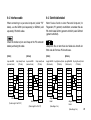
1
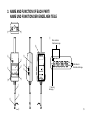
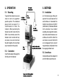
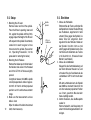
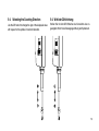
Digital Indicator / Digital Messuhr
U12B / U30B / U60B
Read all the instructions in the manual carefully before use and strictly follow them.
Keep the manual for future references.
Lesen Sie die ganze Anleitung vor dem Betrieb aufmerksam durch und folgen Sie beim Betrieb des Geräts den
Anweisungen. Bewahren Sie diese Bedienungsanleitung zum späteren Nachlesen griffbereit auf.
Instruction Manual / Bedienungsanleitung
Warning : This equipment has been tested and found to
comply with the limits for a Class A digital device, pursuant to
Part 15 of the FCC Rules. These limits are designed to provide
reasonable protection against harmful interference when the
equipment is operated in a commercial environment. This
equipment generates, uses, and can radiate radio frequency
energy and, if not installed and used in accordance with the
instruction manual, may cause harmful interference to radio
communications. Operation of this equipment in a residential
area is likely to cause harmful interference in which case the
user will be required to correct the interference at his own
expense.
You are cautioned that any changes or modifications not
expressly approved in this manual could void your authority to
operate this equipment.
Safety Precautions
Magnescale Co., Ltd. products are designed in full consideration of safety. However,
improper handling during operation or installation is dangerous and may lead to fire, electric
shock or other accidents resulting in serious injury or death. In addition, these actions may
also worsen machine performance.
Therefore, be sure to observe the following safety precautions in order to prevent these types
of accidents, and to read these "Safety Precautions" before operating, installing, maintaining,
inspecting, repairing or otherwise working on this unit.
Warning indication meanings
The following indications are used throughout this manual, and their contents should be
understood before reading the text.
Warning
Failure to observe these precautions may lead to fire, electric shock or other accidents
resulting in serious injury or death.
Caution
Failure to observe these precautions may lead to electric shock or other accidents resulting in (1)
injury or damage to surrounding objects.
Warning
• Do not damage, modify, excessively bend, pull on, place heavy objects on or heat the
cable, as this may damage the cable and result in fire or electric shock.
• Do not disassemble or modify the unit, as this may result in injury or electric shock.
These actions may also damage the internal circuitry.
Caution
• The unit does not have an explosion-proof structure. Therefore, do not use the unit in
an atmosphere charged with inflammable gases as this may result in fire.
• Do not use the unit in places where it may receive excessive shocks. Otherwise the
inside of the unit may be damaged or the unit may become unable to produce normal
output signals.
• Be sure to turn off the power before connecting or disconnecting connectors in oder to
prevent damage or misoperation.
(2)
Sicherheitsmaßnahmen
Bei dem Entwurf von Magnescale Co., Ltd. Produkten wird größter Wert auf die Sicherheit
gelegt. Unsachgemäße Handhabung während des Betriebs oder der Installation ist jedoch
gefährlich und kann zu Bränden, elektrischen Schlägen oder anderen Unfällen führen, die
schwere Verletzungen oder Tod zur Folge haben können. Darüber hinaus kann falsche
Anwendung die Leistung der Maschine verschlechtern.
Beachten Sie daher unbedingt die besonders hervorgehobenen Sicherheitshinweise in dieser
Bedienungsanleitung, um derartige Unfälle zu verhüten, und lesen Sie die folgenden
Sicherheitsmaßnahmen vor der Inbetriebnahme, Installation, Wartung, Inspektion oder
Reparatur dieses Gerätes oder der Durchführung anderer Arbeiten durch.
Bedeutung der Warnhinweise
Bei der Durchsicht dieses Handbuchs werden Sie auf die folgenden Hinweise und Symbole
stoßen. Machen Sie sich mit ihrer Bedeutung vertraut, bevor Sie den Text lesen.
Warnung
Eine Missachtung dieser Hinweise kann zu Bränden, elektrischen Schlägen oder anderen
Unfällen führen, die schwere Verletzungen oder Tod zur Folge haben können.
Vorsicht
Eine Missachtung dieser Hinweise kann zu elektrischen Schlägen oder anderen Unfällen führen,
die Verletzungen oder Sachbeschädigung der umliegenden Objekte zur Folge haben können.
(3)
Warnung
• Das Kabel nicht beschädigen, verändern, übermäßig knicken, daran ziehen, schwere
Objekte darauf stellen oder es erwärmen, da es hierdurch beschädigt und ein Feuer
oder ein elektrischer Schlag hervorgerufen werden kann.
• Das Gerät nicht zerlegen oder verändern, da dies zu Verbrennungen oder elektrischen
Schlägen führen kann. Durch derartige Maßnahmen können auch die internen
Stromkreise beschädigt werden.
Vorsicht
• Das Gerät ist nicht explosionsgeschützt. Es darf daher keinesfalls in einer Umgebung
verwendet werden, die brennabare Gase enthält, da hierdurch ein Feuer entstehen
könnte.
• Das Gerät an Stellen nicht verwenden, wo das starken Erschütterungen ausgesetzt ist,
da hierdurch das Innere des Geräts beschädigt werden könnte oder das Gerät normale
Ausgänge nicht ausgeben könnte.
• Unbedingt darauf achten, dass die Stromversorgung ausgeschaltet wird, ehe der
Steckverbinder abgetrennt wird, damit es nicht zu Schäden oder Fehlfunktionen
kommt.
(4)
TABLE OF CONTENTS
INHALTSVERZEICHNIS
1.
2.
3.
4.
1.
2.
3.
4.
5.
6.
7.
8.
9.
FEATURES ................................................................... 1
SPECIFICATIONS ........................................................ 2
NAME AND FUNCTION OF EACH PART .................... 3
PRECAUTIONS
4-1. General precautions ............................................. 7
4-2. Operating precautions .......................................... 8
OPERATION
5-1. Mounting ............................................................. 11
5-2. Connection ......................................................... 11
5-3. Setup .................................................................. 12
5-4. Selecting the Counting Direction ........................ 13
5-5. Measurement mode ........................................... 14
5-6. Alarm .................................................................. 14
5-7. Measuring the Runout ........................................ 15
5-8. Measuring Flatness ............................................ 18
INPUT/OUTPUT INTERFACE
6-1. Connector ........................................................... 21
6-2. Specifications of RS-232C Interface .................. 22
6-3. Command ........................................................... 23
6-4. Interface cable .................................................... 29
BEFORE YOU TAKE IT FOR FAILURE ..................... 30
ACCESSORIES (SOLD SEPARATELY) .................... 31
DIMENSIONS ............................................................. 32
5.
6.
7.
8.
9.
MERKMALE .................................................................. 1
TECHNISCHE DATEN .................................................. 2
NAME UND FUNKTION DER EINZELNEN TEILE ....... 3
ALLGEMEINE HINWEISE FÜR DEN BETRIEB
4-1. Allgemeine Hinweise ............................................ 7
4-2. Hinweise für den Betrieb ...................................... 8
BETRIEB
5-1. Installation .......................................................... 11
5-2. Anschluss ........................................................... 11
5-3. Einrichten ........................................................... 12
5-4. Wahl der Zählrichtung ........................................ 13
5-5. Messfunktionen .................................................. 14
5-6. Alarm .................................................................. 14
5-7. Messung der Unrundheit .................................... 15
5-8. Messung der Ebenheit ....................................... 18
E/A SCHNITTSTELLE
6-1. Steckverbinder ................................................... 21
6-2. Daten der RS-232C-Schnittstelle ....................... 22
6-3. Befehle ............................................................... 23
6-4. Schnittstellenkabel ............................................. 29
STÖRUNGSÜBERPRÜFUNGEN ............................... 30
SONDERZUBEHÖR ................................................... 31
ABESSUNGEN ........................................................... 32
i
ii
1. FEATURES
1. MERKMALE
• High accuracy: 0.002 mm/0.0001" (U12B, U30B)
0.003 mm/0.00015" (U60B)
• Provided with input/output interface (RC-232C) and, when
connected to the personal computer, capable of various
data processing.
• Memory function enables max., min., and peak-to-peak
value to be measured all at a time by one measuring.
• Easy-to-read, high-contrast LCD on a slant display panel.
• Resolution: 0.001 mm/0.00005"
• Hohe Genauigkeit: 0,002 mm (U12B, U30B)
0,003 mm (U60B)
• Die Messuhr ist mit einer V24-Schnittstelle (RS-232C)
ausgestattet, die bei Anschluss an einen Personal-Computer
eine Verarbeitung verschiedener Daten ermöglicht.
• Dank der Memory-Funktion können mit einem einzigen
Messvorgang gleichzeitig Höchst-, Mindest-, und
Spitzenwerte erfasst werden.
• Leicht abzulesende, kontrastreiche Flüssigkristallanzeige
auf einer schrägen Konsolenfläche.
• Auflösung: 0,001 mm
1
2. SPECIFICATIONS
2. TECHNISCHE DATEN
Item
U12B-F
U30B-F
U60B-F
Gegenstand
U12B-F
U30B-F
U60B-F
Measuring range
12 mm/0.5"
30 mm/1.2"
60 mm/2.4"
Messbereich
12 mm
30 mm
60 mm
Resolution
Accuracy
(at 20 ºC/68 ºF)
0.001 mm/0.00005"
0.002 mm/0.0001"
1.3 N or less
1.5 N or less
2.2 N or less
Luftabheber-Betätigungshub
At full-stroke
32 mm/1.26"
Feeler tipped with 3 mm dia. Carbide ball (DZ-123)
Detection method
Optical (Linear scale)
Display element
LCD (6 digits, “–” display)
0,001 mm
0,002 mm
0,003 mm
Umsetzfehler
±1 Zählimpuls
Messkraft (bei 20 ºC)
1,3 N oder weniger 1,5 N oder weniger 2,2 N oder weniger
bei vollem Hub
Ablesesystem
Optisch (Linearer Maßstab)
Anzeige-Element
Flüssigkristall (6 Stellen, „–“ Anzeige)
Höchste
Ansprechgeschwindigkeit
0,4 m/s
Max. response speed
0.4 m/s 15.7 inch/s
Betriebstemperatur
und -luftfeuchtigkeit
0 ~ 40ºC (keine Kondensation)
0 ~ 40ºC/32 ~ 104ºF (no condensation)
–10 ~ 50ºC/14 ~ 122ºF (no condensation)
Lagertemperatur
und -luftfeuchtigkeit
–10 ~ 50ºC (keine Kondensation)
Storage temperature
and humidity
Mass
Consumption current
Power supply
Accesories
Schaftdurchmesser
0
ø 8 –0.015 mm
190 g
0
0.315" –0.0006" dia.
230 g
300 g
100 mA or less
Masse
Stromverbrauch
Stromversorgung
• DC 6V ±10 % (With DC IN jack used)
• DC6 to 9V (With Data I/O connector used)
Lift Lever
Wrench ∗1
∗1: Used when removing and attaching the measuring feeler.
32 mm
Taster mit Hartmetallkugel von 3 mm Durchm. (DZ-123)
Operating temperature
and humidity
Stem diameter
2
Genauigkeit (bei 20 ºC)
Messtaster
Release - operated stroke
Measuring feeler
0.003 mm
0.00015"
Maximum ±1 count
Quantizing error
Measuring force
(at 20 ºC/68 ºF)
Auflösung
Zubehör
190 g
ø8 0
–0.015 mm
230 g
300 g
100 mA oder weniger
• 6 V Gleichstrom ±10 %
(bei Verwendung der Buchse DC IN)
• 6 bis 9 V Gleichstrom
(bei Verwendung der Daten-Ein-/Ausgabebuchse)
Hubhebel
Schlüssel ∗1
∗1: Wird zum Abnehmen und Anbringen des Messtasters verwendet.
3. NAME AND FUNCTION OF EACH PART/
NAME UND FUNKTION DER EINZELNEN TEILE
DC IN
!1
6V
DATA OUT
!0
t
!6
r
Mode indicator
Funktionsanzeige
!5
POWER
M
t
ON
OFF
MAX MIN P-P
in
u
y
!4
mm
mm
o
DIGITAL
MODE
Unit indicator
Maßeinheit-Anzeige
INDICATOR
RECALL
RESET
DIR
MEM.CL
i
!2
q
“–” indicator
Anzeige „–“
w
!3
e
3
0
0
q Stem: ø8 –0.015
mm/0.315" –0.0006"
dia
w Spindle: ø5 mm/0.2" dia
e Feeler
Using ø3 carbide ball. M2.5 set screw is used.
Can be interchangeably replaced with other makers’ feelers.
r Power switch: Used to turn on and off the power.
t LCD
6 digits, “–” and mode indicators.
:
Indicates the Memory mode.
MAX.: Indicates a maximum is displayed.
MIN.: Indicates a minimum is displayed.
P-P: Indicates a peak-to-peak value is displayed.
y Mode button [MODE]
Used to switch between the Standard mode and the Memory
mode.
Standard mode: Used for normal measurement. The
values in memory are not varied except
by a press of the reset button.
Memory mode: Used for measurements of peak values
(max. and min.) and peak-to-peak values.
4
0
q Schaft: ø8 –0,015
mm
w Spindel: ø5 mm
e Taster
Verwendung einer ø3-Hartmetallkugel. Gewinde M2,5.
Kann durch Taster anderer Hersteller ersetzt werden.
r Ein/Ausschalter: Zum Ein- und Ausschalten.
t Flüssigkristallanzeige
6 Stellen, „–“ & Vorzeichen Funktionsanzeige
:
Funktionsanzeige (Mode)
MAX.: Höchstwert wird angezeigt
MIN.: Mindestwert wird angezeigt
P-P: P.-P.-Wert wird angezeigt
y Funktionsumschalter [MODE]
Zum Umschalten zwischen Standard-und Speicherfunktionen.
Standardfunktion: Für normale Messungen. Die Werte
im Speicher werden nur bei Drücken
des „Reset“- Schalters gelöscht.
Speicherfunktion: Dient zur Messung der Spitzenwerte
(max. und min.) und der P.-P.-Werte
(Spannweite).
u Memory recall button [RECALL]
Used to switch the display between the present value,
max., min., and peak-to-peak value in this sequence.
i Reset/Memory clear button [RESET/MEM.CL]
Used for display zeroset and memory clearance.
[Mode] The function varies according to the measurement
mode selected by the mode button.
Standard mode: The value displayed and those in memory are all reset, displaying “0.000/
0.00000” as the present value.
Memory mode:
The values in memory are cleared.
The MAX and MIN memory stores the
present value and the peak-to-peak
memory stores “0.000/0.00000”
o DIR switch: Used to select the counting derection.
!0 Data I/O connector: Used for RS-232C interface.
!1 DC IN jack: Receives the AC adaptor plug.
u (Recall) Speicher-Aufruf-Schalter [RECALL]
Umschaltung der Anzeige vom vorliegenden Wert zum
Max.-/Min. Wert und P.-P.-Wert (Spannweite), in dieser
Reihenfolge.
i Reset/Memory Clear Schalter [RESET/MEM.CL]
Zur Rückstellung der An-zeige auf Null und Löschen des
Speichers
[Mode] Die Funktion wechselt entsprechend der mit dem
Funktionsschalter gewählten Messfunktionen.
Standardfunktion: Alle Werte einschließlich der Speicherwerte werden zurückgestellt, als gegenwärtiger Wert wird „0.000/0.00000“
angezeigt.
Speicherfunktion: Die Speicherwerte werden gelöscht. Der
MAX und MIN Speicher speichert den
augenblicklichen Wert, und der P.-P.Speicher speichert „0.000/0.00000“.
o DIR-Schalter:
Zur Wahl der Zählrichtung
!0 Daten E/A-Anschluss: Für RS-232C Schnittstelle
!1 DC IN-Anschluss: Zum Einstecken des Netz-AdapterSteckers
5
!2 Air Release mounting hole
The Air Release DZ173 (sold separately) may be mount-ed.
!3 Lift lever
Used to move the spindle without employing the release.
!4 in/mm selector
Used to switch between in/mm on dis-play.
!5 Cover
Please do not remove the cover.
!6 Identification plate
This displays the model name and serial number.
6
!2 Anschlussöffnung für Luftabheber
Hier kann der Luftabhe-ber DZ173 (Sonderzu-behör)
angeschlossen werden
!3 Hubhebel
Zur Bewegung der Spindel ohne Benützung des
Luftabhebers
!4 Zoll/mm-Wahlschalter
Zur Wahl zwischen Anzeige in Zoll (in) und mm.
!5 Akkuabdeckung
Bitte nicht entfernen.
!6 Typenschild
Auf diesem Schild sind Modellbezeichnung und
Seriennummer angegeben.
4. PRECAUTIONS
4-1. General precautions
• Before and/or during operations, be sure to check that our
products function normally.
• Provide sufficient safeguard to prevent extensive damages
in case our products should develop malfunction.
• If our products are used without regard to the specifications
and instructions, or if they are remodeled by yourself, their
functions and performance as specified will not be
guaranteed.
• If our products are used in combination with other devices
than those we recommend, they may not function satisfactorily depending on the operating conditions and environments. Make full study, therefore, of the compatibility
before use.
• Designs and appearances are subject to change without
prior notice.
4. ALLGEMEINE HINWEISE FÜR
DEN BETRIEB
4-1. Allgemeine Hinweise
• Überprüfen Sie vor oder während des Betriebs, ob die
Messuhr normal funktioniert.
• Sorgen Sie für geeignete Sicherheitsmaßnahmen zum
Schutz vor Schäden bei Gerätestörungen.
• Wenn das Produkt nicht entsprechend den Spezifikationen
und Anweisungen verwendet wird, oder wenn er vom
Anwender selbst umgebaut wird, ist Funktion und Leistung
gemäß den Angaben nicht gewährleistet.
• Wenn die Messuhr zusammen mit anderen, nicht von uns
empfohlenen Geräten eingesetzt wird, besteht die
Möglichkeit, dass sie nicht zufriedenstellend arbeitet, je
nach Betriebsbedingungen und Umfeld. Prüfen Sie deshalb
vor dem Gebrauch eingehend die Kompatibilität.
• Änderungen des Designs und der äußeren Aufmachung
vorbehalten.
7
ø8.5 oder
weniger
ø4
ø1.7
ø8.5/0.33" dia
or less
• Das für die Stromversorgung der Messuhr verwendete
Netzgerät muss den Ausgangs-Nennwerten und der
Steckerpolarität entsprechen, um eine mögliche
Funktionsstörung zu vermeiden.
Nennspannung: 6 V Gleichstrom ±10 % V Gleichstrom
Nennstromstärke: min. 100 mA
Steckerpolarität: GLEICHSTROMBUCHSE MIT
VEREINHEITLICHTER POLARITÄT
Steckerabmessungen:
ø4/0.16"
4-2. Hinweise für den Betrieb
• The AC adaptor used to power the Indicator should meet the
requirements of the output rating and the plug polarity to
avoid possible malfunction.
Rated power voltage : 6 VDC ±10 % VDC
Rated power current : 100 mA min.
Power plug polarity : UNIFIELD POLARITY TYPE DC
JACK
Power plug dimensions :
ø1.7/0.07"
4-2. Operating precautions
9.2 mm/0.36" or more
9.2 mm oder mehr
By connecting such adaptor to the dedicated printer, the
Indicator can also be powered.
• The Indicator is not dustproof or water-resistant.
8
Wenn ein derartiger Adapter an den dedizierten Drucker
angeschlossen wird, kann auch die Messuhr mit Strom
versorgt werden.
• Die Messuhr ist nicht staubdicht oder wassergeschützt.
• Do not use or leave the Indicator in environments at a
temperature of more than 40°C/104°F such as places
exposed to the direct sun rays, near a heater, etc.
• When pulling off the AC adaptor from the AC outlet, hold its
body. Pulling the cord may cause open connections. Remove
the AC adaptor from the AC outlet when it is not to be used
for a long time.
• Move the spindle slowly. When it is moved at a speed
exceeding the counter’s max. response speed, “Error” is
displayed and measurement becomes impossible.
Be careful not to fall the feeler as the measured object or the
table may be damaged.
• When using AC adaptor, do not use the same power source
as other units in use of high voltage or current.
• Die Messuhr sollte nicht in einer Umgebung eingesetzt oder
aufgestellt werden, wo Temperaturen von mehr als 40°C
auftreten, z.B. an Stellen, die der direkten Sonneneinstrahlung ausgesetzt sind, neben Heizkörpern usw.
• Zum Abtrennen des Netz-Adapters von der Steckdose
fassen Sie am Adapter selbst und ziehen niemals am Kabel,
um eine Beschädigung zu vermeiden. Bei längerer Nichtverwendung der Messuhr trennen Sie den Netz-Adapter
vom Netz ab.
• Bewegen Sie die Spindel langsam. Wenn die Geschwindigkeit der Spindelbewegung die maximale Ansprechgeschwindigkeit des Zählers übersteigt, wird „Error“
angezeigt, und es kann nicht mehr gemessen werden.
Lassen Sie den Fühler nicht fallen, da sonst das Messobjekt
oder der Messtisch beschädigt werden kann.
• Bei Verwendung eines Netz-Adapter schließen Sie diesen
nicht zusammen mit Geräten mit hoher Leistungsaufnahme
an ein gemeinsames Netz an.
9
• When attaching and removing the feeler, use the wrench
provided. Make sure that the torque applied to the spindle
is below 0.1 N · m, or damage may result.
Tighten the feeler with a tightening torque of about 0.05 to
0.06 N · m.
It is recommended to use a screw lock to prevent loosening
of the feeler.
• Verwenden Sie zum Anbringen und Abnehmen des
Masstasters nur den mitgelieferten Schlüssel. Achten Sie
darauf, dass das auf die Spindel einwirkende Moment unter
0,1 N · m liegt, da sie anderenfalls beschädigt wird.
Ziehen Sie den Masstaster mit einem Anzugsmoment von
etwa 0,05 bis 0,06 N · m fest.
Um eine Lockerung des Messtasters zu vermeiden wird
empfohlen, eine Schraubensicherung zu verwenden.
Spindel
Spindle
Stem
Feeler
Wrench
10
• Except when using a flat-face measuring feeler, using a
nominal 2.5 spring washer is recommended to prevent the
measuring feeler from becoming loose.
• Make sure the spindle surface is clean as dust and oil on it
may hinder its easy movement. Wipe the spindle surface
with alcohol-moistened cloth, when necessary.
• Wipe the dirt off the body and the display with gauze.
To remove heavy dirt, apply a small amount of neutral
detergent to the gauze. Do not use organic solvent.
Schalt
Messtaster
Schlüssel
• Die Verwendung eines Federrings mit einem Nennmaß von
2,5 wird, außer im Falle eines Flachkopf-Messtasters,
empfohlen, um Lockerung des Messtasters zu verhüten.
• Achten Sie darauf, dass die Spindeloberfläche sauber ist,
da Staub und Ölablagerung die Leichtgängigkeit behindern
können. Falls erforderlich, reinigen Sie die Spindeloberfläche
mit einem alkoholgetränkten Tuch.
• Das Gehäuse und die Anzeigefläche reinigen Sie mit Gaze.
Zur Entfernung stärkerer Verschmutzungen können Sie ein
neutrales Reinigungsmittel verwenden. Keine organischen
Lösungsmittel verwenden!
5. OPERATION
5. BETRIEB
5-1. Mounting
5-1. Installation
To position the Indicator, be sure to
chuck its stem at its uppermost
possible portion. The dedicated
gauge stand (see page 31) is
recommended to mount the
Indicator. When positioning the
Indicator by other means than the
DZ521, be extremely careful the
Indicator is not in contact with any
set screws. Use care not to chuck
the stem too tight as this may hinder
easy movement of the spindle.
Zur Positionierung der Messuhr
spannen Sie sie am obersten Teil
des Schaftes ein. Verwenden Sie
möglichst den Messtisch DZ521
(siehe Seite 31). Wird dieser Ständer
nicht verwendet, muss äußerst
sorgfältig darauf geachtet werden,
dass keine Justierschraube usw. an
die Messuhr anstößt. Achten Sie
auch darauf, dass der Schaft nicht
zu fest eingespannt wird, da sonst
mög-licherweise die Spindel in ihrer
Be-wegung behindert wird.
5-2. Connection
Insert the AC adaptor DC plug in the
DC-IN jack of the Indicator.
5-2. Anschluss
Verbinden Sie den Netz-Adapter mit
der DC IN-Buchse der Messuhr.
11
5-3. Setup
1. Mounting the Lift Lever
Remove feeler and hold the spindle.
Press the lift lever’s opening, lower end
first, against the spindle until they firmly
engage. Adjust the height of the lift lever
with respect to the spindle. Be extremely
careful not to exert too great a force
transverse to the spindle. (See section
4-2, “Operating Precautions”, for the
procedure for removing the feeler.)
2. Mounting the Air Release
Remove the rubber cap on the left side of
the Indicator and screw in the threaded
end of the DZ173 Air Release slightly
upward.
Using the air release, the U60B’s spindle
can only be operated a stroke of approx.
32 mm/1.26" from its farthest projected
position out of its whole measurement
range.
3. Make sure the measurement sur-face
table is clean
Wipe the table with alcohol-moistened
cloth,
when necessary.
12
5-3. Einrichten
Spindle
Spindel
Lift lever
Hubhebels
1. Anbau des Hubhebels
Entfernen Sie den Taster, und halten Sie
die Spindel fest. Drücken Sie die Öffnung
des Hubhebels, beginnend mit dem
unteren Ende, gegen die Spindel, bis
beide Teile fest eingreifen. Dann
regulieren Sie die Höhe des Hebels an
der Spindel. Vorsicht: nicht zu stark
seitlich gegen die Spindel drücken. (Das
Verfahren zum Abnehmen des Tasters
ist in Abschnitt 4-2, „Hinweise für den
Betrieb“, beschrieben.)
2. Anbau des Luftabhebers
Klappen Sie die Gummiabdeckung auf
der linken Seite der Messuhr auf, und
schrauben Sie das Gewindeende des
Luftabhebers DZ173 leicht nach oben
ein.
Mit dem Luftabheber kann die Spindel
des U60B nur um einem Hub von 32 mm
von ihrer weitesten projizierten Position
aus ihrem gesamten Messbereich
heraus betätigt werden.
3. Achten Sie darauf, dass die Messplatte
sauber ist
Wenn erforderlich, die Messplatte mit
einem mit Alkohol angefeuchteten Tuch
reinigen.
5-4. Selecting the Counting Direction
5-4. Wahl der Zählrichtung
Use the DIR switch to change the sign of the displayed value
with respect to the spindle’s movement direction.
Stellen Sie mit dem DIR-Schalter das Vorzeichen des angezeigten Werts für die Bewegungsrichtung der Spindel ein.
mm
mm
DIR
DIR
13
5-5. Measurement mode
5-5. Messfunktionen
1. Standard mode
Turning on the power sets the Indicator to the Standard
mode. Press the RESET button to zeroset the datum point
for normal measurements.
1. Normalfunktion
Mit Einschalten des Stroms stellt sich die Messuhr auf die
Standardfunktion ein. Drücken Sie den RESET-Schalter,
um den Ausgangspunkt für normale Messungen auf Null zu
stellen.
2. Memory mode
Press of the MODE button changes the Standard mode to
the Memory mode, with “ ” displayed at the uppermost left
in the LCD. In this mode, the peak values (max. and min.)
and the peak-to-peak value are stored in memory.
This function enables the runout, sag, surface flatness, etc.
to be measured. The max., and peak-to-peak value can be
taken into memory by allowing the feeler to follow the
surface just once.
5-6. Alarm
When the spindle is moved at a speed exceeding the max.
response speed, “Error” is displayed. In this case, press the
RESET button and perform the measuring operation from the
14 start again.
2. Speicherfunktion
Durch Drücken des MODE-Schalters wird von Standardfunktion auf Speicherfunktion umgeschaltet, wobei oben
links in der Flüssigkristallanzeige ein „ “ erscheint. Bei
dieser Funktion werden die Spitzenwerte (max. und min.)
sowie die P.-P.-Werte (Spannweite) festgehalten. Mittels
dieser Funktion können Unrundheit, Durchhang,
Oberflächen Ebenheit usw. gemessen werden. Die
Maximal-, Minimal- und P.-P.-Werte können mit einem
einzigen Abtastvortastvorgang der Oberfläche gespeichert
werden.
5-6. Alarm
Wenn die Spindelgeschwindigkeit die maximale Ansprechgeschwindigkeit überschreitet, wird „Error“ angezeigt. In diesem
Fall drücken Sie den RESET-Schalter und führen Sie die
Messung nochmals durch.
5-7. Measuring the Runout
5-7. Messung der Unrundheit
To measure the runout, follow the procedure below.
Zur Messung der Unrundheit gehen Sie wie unten beschrieben
vor.
Indicator
Messuhr
Object measured
Zu messendes Objekt
Runout
Unrundheit
The shaft is rotated.
Die Welle wird gedreht
15
Procedure
Vorgang
1. Position the Indicator feeler
with respect to the measured
object as shown.
1. Den Taster der Messuhr wie
gezeigt auf das zu messende
Objekt ansetzen.
Operating/Bedienung
Display/Anzeige
mm
2. Apply power to the Indicator.
2. Messuhr einschalten.
M
[ MODE ]
mm
3. Set the Indicator to the Memory
mode. Press the RECALL button three times to select the
peak-to-peak value display.
3. Messuhr auf Speicherfunktion
einstellen. RECALL-Schalter
dreimal drücken, um die Anzeige des P.-P.-Werts zu
erhalten.
[ RECALL ]
↓
[ RECALL ]
↓
[ RECALL ]
M
MAX
mm
M
MIN
mm
M
P-P
mm
4. Turn the shaft at least 360° to
measure the peak-to-peak
value.
16
4. Welle mindestens um 360°
drehen, um den P.-P.-Wert zu
messen (Spannweite).
M
P-P
B
mm
• To Renew Measuring
To check the measurements just obtained or measure
another object, follow the procedure below.
• Erneute Messung
Zur Überprüfung der soeben erhaltenen Messung oder zur
Messung eines anderen Objekts verfahren Sie wie folgt:
Procedure
Vorgang
Operating/Bedienung
5. Press the RESET button to
clear the memory. See Note
below.
5. RESET-Schalter drücken, um
den Speicher zu löschen.
Siehe Anmerkung unten.
[ RESET ]
6. Turn the shaft.
6. Welle drehen.
Display/Anzeige
M
P-P
mm
M
P-P
mm
Note: In the Memory mode, the press of the RESET button
only clears the memory and the datum point is preserved.
The press of the RESET button clears the values
stored in the memory, setting the present value in the
MAX/MIN memory and 0.000 in the peak-to-peak
memory.
Ex.: Present value = 12.345 mm
MAX 12.345
MIN 12.345
P–P
0.000
Anmerkung: In der Speicherfunktion wird bei Betätigung des
RESET-Schalters nur der Speicher gelöscht,
während der Ausgangspunkt erhalten bleibt.
Die Betätigung des RESET-Schalters löscht die
Werte im Speicher, wobei der augenblickliche
Wert im MAX/MIN-Speicher festgehalten und
der P.-P.-Speicher auf 0.000 gestellt wird.
Beispiel: Augenblicklicher Wert = 12,345 mm
MAX 12,345
MIN 12,345
P–P
0,000
17
5-8. Measuring Flatness
5-8. Messung der Ebenheit
To measure the max. height, min. height, and the flatness,
follow the procedure below.
Zur Messung der maximalen Höhe, minimalen Höhe und
Ebenheit gehen Sie wie folgt vor:
B
C
20.005
20.000
19.992
19.980
A
Object measured
Zu messendes Objekt
0.000
Measurement table
Massplatte
18
Procedure
Vorgang
Operating/Bedienung
1. Turn on the power of the Indicator, place the feeler on the
datum surface and press the
RESET button. (A)
2. Place the feeler on the surfac to
be measured and set the Indicator to the Memory mode. (B)
3. Move the object to be measured,
allowing the feeler to follow the
surface under measurement.
(B to C)
4. Press the RECALL button to
display the max.
5. Press the RECALL button to
display the min.
6. Press the RECALL button to
display the peak-to-peak value.
1. Messuhr einschalten, den Taster
auf die Messplatte setzen und
RESET-Schalter drücken. (A)
[ RESET ]
2. Taster auf die zu messende Oberfläche aufsetzen und Messuhr
auf Speicherfunktion stellen. (B)
3. Das zu messende Objekt bewegen, so dass der Taster der
Oberfläche folgt und sie misst.
(von B nach C)
4. RECALL-Schalter zur Anzeige
des Maximal-Werts drücken.
5. RECALL-Schalter zur Anzeige
des Minimal-Werts drücken.
6. RECALL-Schalter zur Anzeige
des P.-P.-Werts drücken.
[ MODE ]
Display/Anzeige
mm
M
mm
M
mm
M
B
MAX
[ RECALL ]
[ RECALL ]
mm
M
B
MIN
mm
[ RECALL ]
M
P-P
B
mm
Max. height/Max. Höhe/Max. Höhe: 20.005 mm
Min. height/Min. Höhe/Min Höhe : 19.980 mm
Flatness/Ebenheit
: 0.025 mm
19
• To Renew Measuring
To check the measurements just obtained or measure
another object, follow the procedure below.
Procedure
Vorgang
Operating/Bedienung
7. Press the RESET button to
clear the memory.
7. RESET-Schalter drücken, um
den Speicher zu löschen.
[ RESET ]
8. Move the object to be measured, allowing the feeler to follow the surface of the object.
(C→B)
8. Das zu messende Objekt bewegen, so dass der Abtaster der
Oberfläche folgt und sie misst.
(von B nach C)
9. Press the RECALL button two
times to display the max.
9. RECALL-Schalter zur Anzeige
des Maximalwerts zweimal
drücken.
10. RECALL-Schalter zur Anzeige
des Minimal-Werts drücken.
10.Press the RECALL button to
display the min.
Note: To stop the recording of data halfway, press the MODE
button to leave the Memory mode. In the Standard
mode, the spindle movement does not affect the data in
memory.
20
• Erneute Messung
Zur Überprüfung der soeben erhaltenen Messung oder zur
Messung eines anderen Objekts verfahren Sie wie folgt:
Display/Anzeige
M
P-P
mm
M
P-P
mm
[ RECALL ]
↓
[ RECALL ]
M
mm
M
MAX
mm
[ RECALL ]
M
MIN
B
mm
Anmerkung: Um die Aufzeichnung der Daten während des
Messvorgangs zu unterbrechen, drücken Sie
den MODE-Schalter, um die Speicherfunktion
abzuschalten. In der Standardfunktion werden
die Daten im Speicher von der Spindelbewegung
nicht beeinflusst.
6. INPUT/OUTPUT INTERFACE
6. E/A SCHNITTSTELLE
An RS-232C-compliant interface can be used to perform
measurement data reading, mode switching, and other
operations when connected from the data input/output connector
(8-pin) on top of the unit.
∗ An interface connection requires an interface cable (sold
separately) (DZ252, DZ253A). (See section 6-4.)
Select the cable that matches the specifications of the
connected equipment.
Bei Anschluss an die Daten-Ein-/Ausgabebuchse (8-polig) an
der Oberseite des Gerätes kann eine RS-232C-kompatible
Schnittstelle verwendet werden, um Messdatenausgabe,
Modusumschaltung und andere Operationen durchzuführen.
∗ Für den Schnittstellenanschluss wird ein Schnittstellenkabel
(getrennt erhältlich) (DZ252, DZ253A) benötigt. (Siehe
Abschnitt 6-4.)
Wählen Sie ein Kabel, das den Spezifikationen des
angeschlossenen Gerätes entspricht.
6-1. Connector
6-1. Steckverbinder
The specifications of the connector of the Indicator are shown
below.
Die Daten des Messuhr-Steckverbinders sind unten angegeben.
TCS 7580-01-101 (by Hosiden Corporation)
PinNo. Sign
Signaldirection
Signal name
1
Vin
←
Power supply ∗1
2
SG
↔
Signal grounding
3
RXD
←
Received data
4
TXD
→
Transmitted data
5
CTS
←
Clear to send
6
RTS
→
Reqiest to send
7
(+10V)
→
(+10 V output) ∗2
8
NC
—
—
∗1 It can be use when connecting with the electronic
equipment.
∗2 Although it outputs +10V, do not use it.
TCS 7580-01-101 (von Hosiden Corporation)
8
7
5
2
6
4
3
1
Pin. Nr. Zeichen Signaldirection Name des Signals
1
Vin
←
Spannungsversorgung ∗1
2
SG
↔
Signal-Erde
3
RXD
←
Empfan gene Daten
4
TXD
→
Übertragene Daten
5
CTS
←
Klar zum Senden
6
RTS
→
Anforderung zum Senden
7
(+10 V)
→
(+10 V Ausgabe) ∗2
8
NC
—
—
∗1 Kann bei Anschluss an Elektronikgeräte verwendet
werden.
21
∗2 Nicht verwenden, obwohl +10 V ausgegeben wird.
6-2. Daten der RS-232C-Schnittstelle
6-2. Specifications of RS-232C Interface
Signal
Flow control
Transfer rate
Data length
Parity
Stop bit
Cable length
: Asynchronous, start-stop, half duplex
: Hardware flow control(RTS, CTS)
: 2400 bps
: 8 bit
: No parity
: 1 bit
: 15 m Max.
Signal
Ablaufsteuerung
Übertragungsrate
Datenlänge
Parität
Stoppbit
Kabellänge
Start bit
Startbot
Transmission timing (1 character)
Übertragungszeit (1 Zeichen)
: Asynchron, Start-Stopp, Halbduplex
: Hardware-Ablaufsteuerung (RTS, CTS)
: 2.400 bps
: 8 Bit
: Keine Parität
: 1 Bit
: max. 15 m
Stop bit
Stoppbit
D0 D1 D2 D3 D4 D5 D6 D7
417 µs
4.17 ms ±5%
Next start bit
Nächstes Startbit
22
6-3. Command
6-3. Befehle
Command contents
Befehlserläuterung
Transmission command/
Übertragungsbefehl
Contents/Inhalt
Return/Rückgabe
R
Request for present value display
Anforderung für Gegenwartswert-Anzeige
R □□□□□□□□□□□
F
Request for constant output data
Anforderung für Konstant-Ausgabedaten
F □□□□□□□□□□□
MA
Request for maximum value
Anforderung für Maximalwert
M A □□□□□□□□□□
MI
Request for minimum value
Anforderung für Minimalwert
M I □□□□□□□□□□
MP
Request for peak to peak value
Anforderung für P.-P.-Wert
M P □□□□□□□□□□
MN
Request for present value
Anforderung für Gegenwartswert
M □□□□□□□□□□□
DN
Change standard mode and display present value
Standardmodus ändern und Gegenwartswert anzeigen
AD
DM
Change memory mode and display present value
Speichermodus ändern und Gegenwartswert anzeigen
AD
DA
Display maximum value
Maximalwert anzeigen
AD
DI
Display minimum value
Minimalwert anzeigen
AD
DP
Display peak to peak value
P.-P.-Wert anzeigen
AD
C
Reset/Memory clear
Rücksetzen/Speicher löschen
AC
23
Transmission command/
Übertragungsbefehl
Contents/Inhalt
Return/Rückgabe
P □□□□□□□
Set preset value
Voreinstellwert einstellen
AG
H □□□□□□□
Set comparator upper limit value
Komparator-Obergrenzwert einstellen
AG
L □□□□□□□
Set comparator lower limit value
Komparator-Untergrenzwert einstellen
AG
GO
Display “GO”
„GO“ anzeigen
AG
GU
Display “:” (Upper limit indicate)
„:“ anzeigen (Obergrenze anzeigen)
AG
GN
Display “;” (Lower limit indicate)
„;“ anzeigen (Untergrenze anzeigen)
AG
GC
Clear Upper/Lower limit display
Ober-/Untergrenzwertanzeige löschen
AG
KE
Comparator function ON
Komparatorfunktion EIN
AG
KD
Comparator function OFF
Komparatorfunktion AUS
AG
Note1 : To send a command, either CR (0DH) or LF (0AH) must
be added on as a delimiter.
Note2 : The Indicator returns the data which is added on CR
and LF as a delimiter at any time.
Note3 : The Indicator returns the command below at the time
of malfunction or when it received a command which
is unable to read.
EO : Speed alarm is displayed
EC : Unreadable command is received
24
EF : Indication of overflow is displayed
Hinweis1 : Um einen Befehl zu senden, muss entweder CR
(0DH) oder LF (0AH) als Begrenzungszeichen
hinzugefügt werden.
Hinweis2 : Die Messuhr gibt die als Begrenzungszeichen
hinzugefügten Daten für CR und LF jederzeit wieder.
Hinweis3 : Die Messuhr gibt den nachstehenden Befehl im
Falle einer Funktionsstörung oder bei Empfang
eines unlesbaren Befehls wieder.
EO : Geschwindigkeitsalarm wird angezeigt
EC : Unlesbarer Befehl wird empfangen
EF : Überlaufmeldung wird angezeigt.
Command explanation
Befehlserläuterung
q R (Displayed data readout)
Enables the readout of the current display.
w F (Constant output data)
Data is output constantly. In order to stop output data, press
the RESET/MEM. CL button or send “C” command to the
Indicator at the time of standard mode.
Only “C” command is valid during running “F” command.
Button operation is acceptable at any time.
q R (Ausgabe der angezeigten Daten)
Ermöglicht die Ausgabe der gegenwärtigen Anzeige.
w F (Konstant-Ausgabedaten)
Daten werden konstant ausgegeben. Um die
Datenausgabe zu stoppen, drücken Sie die Taste RESET/
MEM.CL, oder senden Sie im Standardmodus den Befehl
„C“ zur Messuhr.
Während der Ausführung des Befehls „F“ ist nur der Befehl
„C“ gültig.
Tastenbetätigung ist jederzeit akzeptabel.
e M (Ausgabe der Speicherwerte)
Ermöglicht die Ausgabe von Gegenwartswert,
Maximalwert, Minimalwert und P.-P.-Wert, ohne den
Anzeigeinhalt zu ändern.
r D (Wahl der Anzeige)
Ermöglicht die Wahl des Messmodus oder des
Anzeigeinhalts.
t C (Rücksetzen/Speicher löschen)
Anzeige-Nullrücksetzung und Speicherlöschung.
(Ermöglicht die Durchführung der gleichen Operation wie
beim Drücken der Taste RESET/MEM.CL.)
e M (Memory readout)
Enables the readout of the present value, maximum value,
minimum value and peak to peak value without changing
the display contents.
r D (Display select)
Selects the measuring mode or the display contents.
t C (Reset/Memory clear)
Display zero set and memory clear.
(Enables the same operation to be performed as does the
press of the RESET/MEM. CL button.)
25
y P (Preset value setting)
Set the preset value.
The preset value loads to present value to the press of the
RESET/MEM. CL button or send “C” command to the Indicator at standard mode.
u H (Comparator mode upper limit value setting)
Set comparator upper limit value at the time of comparator
mode.
i L (Comparator mode lower limit value setting)
Set comparator lower limit value at the time of comparator
mode.
o G (Comparator sign display)
Enables the indicate any one of “;”, “GO” or “:” on the
LCD of front panel.
!0 K (Comparator mode)
Go/No Go measuring is carried out by comparing data from
the current measuring data to the comparator upper and
lower limits.
The result is indicate any one of “;”, “GO” or “:” on the
LCD of front panel.
26
y P (Einstellung des Voreinstellwerts)
Voreinstellwert einstellen.
Wenn die Taste RESET/MEM.CL gedrückt oder der Befehl
„C“ im Standardmodus zur Messuhr gesendet wird, wird
für den Voreinstellwert der Gegenwartswert geladen.
u H (Komparatormodus-Obergrenzwert-Einstellung)
Der Komparator-Obergrenzwert wird im Komparatormodus
eingestellt.
i L (Komparatormodus-Untergrenzwert-Einstellung)
Der Komparator-Untergrenzwert wird im Komparatormodus
eingestellt.
o G (Komparatorzeichen-Anzeige)
Ermöglicht die Anzeige eines der Zeichen „;“, „GO“ oder
„:“ auf der Flüssigkristallanzeige der Frontplatte.
!0 K (Komparatormodus)
Gut/Schlecht-Messung wird ausgeführt, indem die
gegenwärtigen Messdaten mit dem Komparator-Ober- und
-Untergrenzwert verglichen werden.
Das Resultat ist die Anzeige eines der Zeichen „;“, „GO“
oder „:“ auf der Flüssigkristallanzeige der Frontplatte.
Output data format
Ausgabedatenformat
Return data format
Return data format of R, MA, MI, MP, MN and F
1st byte
: R (In case of sending R command)
M (In case of sending MA, MI, MP or MN
command)
F (In case of sending F command)
2nd byte
: N (In case of present value and standard
mode)
M (In case of present value and standard
mode)
A (In case of maximum value)
I (In case of minimum value)
P (In case of peak to peak value)
3rd byte
: M (Unit : mm)/I (Unit : inch)
4th byte
: Space (20H)
5th byte
: Space (In case of plus value)/– (In case of
minus value)
6 to 12th byte : Numerical data with decimal point
(3-digits integer + decimal point + 3-digits
after the decimal point e.g. 123.456)
• Position of decimal point is fixed at 9th
byte.
• In case that integer parts are 3-digits or
less, space code outputs at this parts
3.456
(20H) e.g.
13 to 14th byte : Delimiter CR LF
Rückgabedatenformat
Rückgabedatenformat von R, MA, MI, MP, MN und F
1. Byte
: R (Im Falle der Sendung des Befehls R)
M (Im Falle der Sendung des Befehls MA,
MI, MP oder MN)
F (Im Falle der Sendung des Befehls F)
2. Byte
: N (Im Falle von Gegenwartswert und
Standardmodus)
M (Im Falle von Gegenwartswert und
Standardmodus)
A (Im Falle des Maximalwerts)
I (Im Falle des Minimalwerts)
P (Im Falle des P.-P.-Werts)
3. Byte
: M (Einheit: mm)/I (Einheit: Zoll)
4. Byte
: Leerstelle (20H)
5. Byte
: Leerstelle (Im Falle eines Pluswerts)/– (Im
Falle eines Minuswerts)
6. bis 12. Byte : Numerische Daten mit Komma
(3-stellige Ganzzahl + Komma + 3 Stellen
nach dem Komma: z.B. 123,456)
• Die Position des Kommas ist auf das 9.
Byte fixiert.
• Für den Fall, dass der Ganzzahlteil 3stellig oder kleiner ist, wird an diesen
Teilen ein Leerstellencode ausgegeben
27
(20H): z.B.
3.456
13. bis 14. Byte : Begrenzungszeichen CR LF
Sending data format
Sending data format of P, H and L
Input numerical data that is signed 6-digits without decimal
point after P, H or L command.
• Setting range : –999999 to +999999
e.g. Preset –1.234mm = Input P–001234 CR
Set to zero
= Input P+000000 CR
• To replace the setting value, overwrite new value.
• When turns off the power, these setting value are lost and
turn on the power then the data set to zero.
• These values are not relation with unit select function.
Therefore, when you input
P+001000 data at inch unit mode and after that change to
mm unit mode, in this case, this value does not convert to
P+025400 but indicate P+001000.
28
Senden des Datenformats
Senden des Datenformats von P, H und L
Geben Sie numerische Daten in der Form von 6 Ziffern mit
Vorzeichen ohne Komma nach dem Befehl P, H oder L ein.
• Einstellbereich: –999999 bis +999999
z.B. Voreinstellung –1.234 mm = Eingabe P–001234 CR
Nullstellung
= Eingabe P+000000 CR
• Um den Einstellwert zu ersetzen, überschreiben Sie ihn
mit dem neuen Wert.
• Beim Ausschalten der Stromversorgung gehen diese
Einstellwerte verloren, und beim Einschalten werden die
Daten auf Null gesetzt.
• Diese Werte stehen nicht mit der Einheitswahlfunktion in
Beziehung. Wenn Sie daher die Daten P+001000 im
Zollmodus eingeben und danach auf den Millimetermodus
wechseln, wird dieser Wert nicht in P+025400
umgewandelt, sondern als P+001000 angezeigt.
6-4. Interface cable
6-4. Schnittstellenkabel
When connecting to a personal computer (called “PC”
below), use the DZ252 (sold separately) or DZ253A (sold
separately) RS-232C cables.
Wenn Sie das Gerät an einen Personal Computer (im
Folgenden „PC“ genannt) anschließen, verwenden Sie das
RS-232C-Kabel DZ252 (getrennt erhältlich) oder DZ253A
(getrennt erhältlich).
Check the number of pins and shape of the PC connector
before purchasing the cable.
[DZ252]
[DZ253A]
8-pin mini-DIN
(main unit side)
[DZ252]
25-pin (male) D-sub
(PC side)
Pin No.
1
2
3
4
5
6
7
8
9
Case
Pin No.
1
2
3
4
5
6
7
8
Case
Pin No.
1
2
3
4
5
6
7
Shielded wire
(Cable length: 2 m/78.74")
Shielded wire
25
Case
(Cable length: 2 m/78.74")
[DZ253A]
8-polig Mini-DIN
(Geräteseite)
9-polig (Buchse) D-Sub 8-polig Mini-DIN 25-polig (Stecker) D-Sub
(PC-Seite)
(PC-Seite)
(Geräteseite)
Stift-Nr.
1
2
3
4
5
6
7
8
Gehäuse
Abgeschirmtes
Kabel
Stift-Nr.
1
2
3
4
5
6
7
8
9
Gehäuse
(Kabellänge: 2 m)
Stift-Nr.
1
2
3
4
5
6
7
8
Gehäuse
Abgeschirmtes
Kabel
Stift-Nr.
1
2
3
4
5
6
7
~
8-pin mini-DIN
(main unit side)
~
9-pin (female) D-sub
(PC side)
Pin No.
1
2
3
4
5
6
7
8
Case
Überprüfen Sie vor dem Kauf des Kabels die Anzahl der
Stifte und die Form des PC-Anschlusses.
25
Gehäuse
(Kabellänge: 2 m)
29
30
7. BEFORE YOU TAKE IT FOR
FAILURE
7. STÖRUNGSÜBERPRÜFUNGEN
Before you conclude the product developed malfunction, check
the following:
Bei Auftreten von Problemen überprüfen Sie die folgenden
Punkte.
1. Failure to display
• Is the power switch set to ON?
• Is the AC adaptor connected fast?
• Is the AC adaptor used the one specified?
1. Keine Anzeige
• Ist der Ein-Schalter auf ON gestellt?
• Ist der Netz-Adapter fest eingesteckt?
• Wird der richtige Netz-Adapter verwendet?
2. Failure to count
• Is the memory display mode not selected?
(Is MAX, MIN, or P-P not displayed?)
• Is Error not displayed?
2. Gerät zählt nicht
• Ist die Speicher-Anzeigefunktion nicht eingestellt?
(Wird MAX, MIN oder P-P nicht angezeigt?)
• Wird Error nicht angezeigt?
3. Accuracy failure
• Is the feeler clean?
• Is the Indicator body fixed firmly?
• Is the feeler fit fast?
3. Fehler bei der Genauigkeit
• Ist der Taster sauber?
• Ist der Messuhr-Körper fest angebracht?
• Ist der Taster fest eingesetzt?
4. Spindle’s uneasy movement
• Is the spindle free from dirt or oil?
• Is the stem not clamped with an excessively great force?
4. Schlechter Lauf der Spindel
• Ist die Spindel frei von Schmutz- oder
Ölablagerungen?
• Ist der Schaft nicht zu fest eingespannt?
8. ACCESSORIES (SOLD
SEPARATELY)
Air Release
Interface cable
Gauge Stand
Feeler
: DZ173
: DZ252, DZ253A
: DZ521 (U12B, U30B)
∗
DZ-501 (U60B)
: DZ-5100
Air Release/Luftabheber
DZ173
Feeler/Taster
DZ-5100
∗ DZ-501 requires set bush DZ-811.
8. SONDERZUBEHÖR
Luftabheber
: DZ173
Schnittstellenkabel : DZ252, DZ253A
Messtisch
: DZ521 (U12B, U30B)
∗
DZ-501 (U60B)
Taster
: DZ-5100
Gauge Stand/Meßtisch
DZ521
size of surface plate/
Meßtischplattegröße
80 × 80 mm
3.15 × 3.15 inch
Gauge Stand/Messtisch
DZ-501
size of surface plate/
Messtischplattengröße
110 × 110 mm
4.33 × 4.33 inch
∗ Für den DZ-501 wird die Einrichtbuchse DZ-811 benötigt.
31
(46)/(1.8")
9. DIMENSIONS/ABMESSUNGEN
U12B
U30B
DC IN
6V
DATA OUT
(46)/(1.8")
60/2.36"
DC IN
6V
DATA OUT
ø12/ø0.47"
60/2.36"
POWER
POWER
MODE
INDICATOR
RECALL
RESET
DIR
mm
DIGITAL
MODE
INDICATOR
RECALL
RESET
DIR
MEM.CL
ø5
ø0.20"
16.4/0.65"
40
1.57"
45
1.77"
ø8
0"
ø0.32" –0.0005"
16
0.63"
6
0.24"
0
–0.015
94/3.7"
27
1.06"
6
0.24"
M12×1
43/1.7"
31
1.2"
MEM.CL
43/1.7"
31
1.2"
174/6.85"
245/9.65"
98/3.86"
98/3.86"
mm
DIGITAL
32
ON
OFF
ON
OFF
16/0.63"
M12×1
0
ø8 –0.015
0"
ø0.32" –0.0005"
40
1.57"
ø5
ø0.20"
Unit
: mm/inch
Maßeinheit
28.5/1.12"
ø12.5/ø0.49"
U60B
58
52 2.28"
2.05"
ON
OFF
mm
DIGITAL
MODE
INDICATOR
RECALL
RESET
DIR
31/1.2"
30
1.18"
MEM.CL
M12×1
0
ø8 –0.015
0"
ø0.32" –0.0005"
16/0.63"
16.4/0.65"
40/1.57"
75/2.95"
DATA OUT
POWER
6
0.24"
6V
124/4.88"
DC IN
365/14.4"
175/6.89"
98/3.86"
(46)/(1.8")
ø5
ø0.20"
Unit
: mm/inch
Maßeinheit
33
34
このマニュアルに記載されている事柄の著作権は当社にあ
り、説明内容は機器購入者の使用を目的としています。
したがって、当社の許可なしに無断で複写したり、説明内
容(操作、保守など)と異なる目的で本マニュアルを使用
することを禁止します。
The material contained in this manual consists of
information that is the property of Magnescale Co., Ltd. and
is intended solely for use by the purchasers of the
equipment described in this manual.
Magnescale Co., Ltd. expressly prohibits the duplication of
any portion of this manual or the use thereof for any
purpose other than the operation or maintenance of the
equipment described in this manual without the express
written permission of Magnescale Co., Ltd.
Le matériel contenu dans ce manuel consiste en
informations qui sont la propriété de Magnescale Co., Ltd.
et sont destinées exclusivement à l'usage des acquéreurs
de l'équipement décrit dans ce manuel.
Magnescale Co., Ltd. interdit formellement la copie de
quelque partie que ce soit de ce manuel ou son emploi pour
tout autre but que des opérations ou entretiens de
l'équipement à moins d'une permission écrite de
Magnescale Co., Ltd.
Die in dieser Anleitung enthaltenen Informationen sind
Eigentum von Magnescale Co., Ltd. und sind ausschließlich
für den Gebrauch durch den Käufer der in dieser Anleitung
beschriebenen Ausrüstung bestimmt.
Magnescale Co., Ltd. untersagt ausdrücklich die
Vervielfältigung jeglicher Teile dieser Anleitung oder den
Gebrauch derselben für irgendeinen anderen Zweck als die
Bedienung oder Wartung der in dieser Anleitung
beschriebenen Ausrüstung ohne ausdrückliche schriftliche
Erlaubnis von Magnescale Co., Ltd.
U12B / U30B / U60B
2-067-035-13
2010.4
Printed in Japan
©2004 Magnescale Co., Ltd.