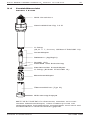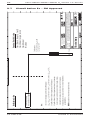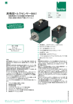
1
InPro® 6850 i, 6900 i & 6950 i Series O2 Sensors Instruction manual Bedienungsanleitung Instructions d’utilisation InPro 6850 i / 6900 i / 6950 i 52 206 349 2 InPro 6850 i / 6900 i / 6950 i O2 Sensor 12 / 25 mm English Page Deutsch Seite 40 Français Page 78 InPro 6850 i / 6900 i / 6950 i 52 206 349 3 © 04 / 13 Mettler-Toledo AG Printed in Switzerland InPro 6850 i / 6900 i / 6950 i O2 Sensor 12 / 25 mm 3 InPro® 6850 i, 6900 i & 6950 i Series O2 Sensors Instruction manual © 04 / 13 Mettler-Toledo AG Printed in Switzerland InPro 6850 i / 6900 i / 6950 i 52 206 349 4 InPro 6850 i / 6900 i / 6950 i O2 Sensor 12 / 25 mm Contents 1 Introduction 2 2.1 2.2 2.3 2.4 2.5 2.6 2.6.1 2.6.2 2.6.3 2.7 Important notes Notes on operating instructions Intended use Safety instructions Examples of some typical applications Use in Ex-zones (not for InPro 6950 i) Ex-classification ATEX (not for InPro 6950 i) Introduction Rated data Special conditions Ex-classification FM approved 6 6 6 7 8 8 9 9 9 10 11 3 3.1 3.2 3.3 3.4 Product description General information Principle Scope of delivery Equipment features 12 12 12 13 14 4 4.1 4.2 4.2.1 4.2.2 Installation Mounting the sensor Connection Connecting the sensor to a AK9 cable Connecting the AK9 cable to the transmitter 15 15 15 15 16 5 5.1 5.2 5.2.1 5.2.2 5.2.3 5.2.4 Operation Start-up and polarizing Calibration Purpose of calibration What you have to know for calibration Single point calibration Dual point calibration 17 17 18 18 18 19 19 6 6.1 6.1.1 6.1.2 6.1.3 6.1.4 6.2 Maintenance Inspection of the sensor Visual inspection Testing the METTLER TOLEDO O2 sensor master Testing the sensor via a transmitter ISM design Changing the electrolyte, the membrane body or the interior body 20 20 20 21 22 23 7 Storage 26 8 8.1 8.2 Product specification Certificates Specifications 27 27 28 9 9.1 9.2 9.3 9.4 9.5 Ordering information Sensors with ISM functionality Accessories Spare parts Recommended transmitters Recommended housings 29 29 29 30 30 31 10 10.1 10.2 10.3 10.4 10.5 10.6 10.7 Theory of the polarographic sensor Introduction Principle of the design of an oxygen electrode Parameters determining current Polarization voltage Temperature Dependence on flow Oxygen partial pressure – oxygen concentration 32 32 32 36 36 37 37 37 InPro 6850 i / 6900 i / 6950 i 52 206 349 5 23 © 04 / 13 Mettler-Toledo AG Printed in Switzerland InPro 6850 i / 6900 i / 6950 i O2 Sensor 12 / 25 mm 1 5 Introduction Thank you for buying the InPro 6850 i / 6900 i / 6950 i sensor from METTLER TOLEDO. The construction of the InPro series employs leading edge technology and complies with safety regulations currently in force. Notwithstanding this, improper use could lead to hazards for the user or a third-party, and/or adverse effects on the plant or other equipment. the operating instructions must be read a Therefore, and understood by the persons involved before work is started with the sensor. The instruction manual must always be stored close at hand, in a place accessible to all people working with the InPro sensor. If you have questions, which are not or insufficiently answered in this instruction manual, please contact your METTLER TOLEDO supplier. He will be glad to assist you. © 04 / 13 Mettler-Toledo AG Printed in Switzerland InPro 6850 i / 6900 i / 6950 i 52 206 349 6 InPro 6850 i / 6900 i / 6950 i O2 Sensor 12 / 25 mm 2 Important notes 2.1 Notes on operating instructions These operating instructions contain all the information needed for safe and proper use of the InPro 6850i / 6900i / 6950i sensor. The operating instructions are intended for personnel entrusted with the operation and maintenance of the sensors. It is assumed that these persons are familiar with the equipment in which the sensor is installed. Warning notices and symbols This instruction manual identifies safety instructions and additional information by means of the following symbols: symbol draws attention to safety instruca This tions and warnings of potential danger which, if neglected, could result in injury to persons and/or damage to property. symbol identifies additional information and h This instructions which, if neglected, could lead to defects, inefficient operation and possible loss of production. 2.2 Intended use METTLER TOLEDO InPro 6850 i / 6900 i / 6950 i sensors are intended solely for inline measurement of the oxygen partial pressure in liquids and gases, as described in this instruction manual. Any use of these sensors which differs from or exceeds the scope of use described in this instruction manual will be regarded as inappropriate and incompatible with the intended purpose. The manufacturer / supplier accepts no responsibility whatsoever for any damage resulting from such improper use. The risk is borne entirely by the user / operator. Other prerequisites for appropriate use include: – compliance with the instructions, notes and requirements set out in this instruction manual. – acceptance of responsibility for regular inspection, maintenance and functional testing of all associated components, also including compliance with local operational and plant safety regulations. – compliance with all information and warnings given in the documentation relating to the products used in conjunction with the sensor (housings, transmitters, etc). – observance of all safety regulations governing the equipment in which the sensor is installed. InPro 6850 i / 6900 i / 6950 i 52 206 349 © 04 / 13 Mettler-Toledo AG Printed in Switzerland InPro 6850 i / 6900 i / 6950 i O2 Sensor 12 / 25 mm 7 – correct equipment operation in conformance with the prescribed environmental and operational conditions, and admissible installation positions. – consultation with Mettler-Toledo Process Analytics in the event of any uncertainties. 2.3 Safety instructions a– The plant operator must be fully aware of the potential risks and hazards attached to operation of the particular process or plant. The operator is responsible for correct training of the workforce, for signs and markings indicating sources of possible danger, and for the selection of appropriate, state-of-the-art instrumentation. – It is essential that personnel involved in the commissioning, operation or maintenance of these sensors or of any of the associated equipment (e.g. housings, transmitters, etc.) be properly trained in the process itself, as well as in the use and handling of the associated equipment. This includes having read and understood this instruction manual. – The safety of personnel as well as of the plant itself is ultimately the responsibility of the plant operator. This applies in particular in the case of plants operating in hazardous zones. – The oxygen sensors and associated components have no effect on the process itself and cannot influence it in the sense of any form of control system. – Maintenance and service intervals and schedules depend on the application conditions, composition of the sample media, plant equipment and significance of the safety control features of the measuring system. Processes vary considerably, so that schedules, where such are specified, can only be regarded as tentative and must in any case be individually established and verified by the plant operator. – Where specific safeguards such as locks, labels, or redundant measuring systems are necessary, these must be provided by the plant operator. – A defective sensor must neither be installed nor put into service. – Only maintenance work described in this operating instruction may be performed on the sensors. – When changing faulty components, use only original spare parts obtainable from your METTLER TOLEDO supplier (see spare parts list, “Section 9.3”). – No modifications to the sensors and the accessories are allowed. The manufacturer accepts no responsibility for damages caused by unauthorised modifications. The risk is borne entirely by the user. © 04 / 13 Mettler-Toledo AG Printed in Switzerland InPro 6850 i / 6900 i / 6950 i 52 206 349 8 2.4 InPro 6850 i / 6900 i / 6950 i O2 Sensor 12 / 25 mm Examples of some typical applications Below is a list of examples of typical fields of application for the oxygen sensors. This list is not exhaustive. Measurement in liquids: – Biotech – Chemical applications – Brewing – Beverage filtration – Filling stations Measurement in gases: – CO2 recovery – CO2 purity – Product storage – Inert production 2.5 Use in Ex-zones (not for InPro 6950 i) For an installation in Ex-zones please a Attention! read the guidelines following hereafter: Ex-classification ATEX: x II 1/2G Ex ia IIC T6/T5/T4/T3 II 1/2D Ex iaD A20/21 x T 69 °C / T 81 °C / T 109 °C / T 161 °C Marking and number of the test certificate: SNCH 01 ATEX 3277 X f Ex-classification FM approved: IS / I, II, III / 1 / ABCDEFG / T6 Ta = 60 °C - 53 800 002; Entity InPro 6850 i / 6900 i / 6950 i 52 206 349 © 04 / 13 Mettler-Toledo AG Printed in Switzerland InPro 6850 i / 6900 i / 6950 i O2 Sensor 12 / 25 mm 2.6 9 Ex-classification ATEX (not for InPro 6950 i) 2.6.1 Introduction According to RL 94/9/EG (ATEX 95) Appendix l, lnPro 6XXX*/*/*/*/* oxygen sensors are devices group ll, category 1/2G and according to RL 99/92/ EG (ATEX 137) may be used in zones 0/1 or 0/2 and gas groups llA, llB and llC that are potentially explosive due to combustible substances in the temperatures classes T3 to T6. For use/installation, the requirements of EN 6007914 must be observed. According to RL 94/9/EG (ATEX 95) Appendix l, lnPro 6XXX*/*/*/*/* oxygen sensors are devices group ll, category 1/2D and according to RL 99/92/ EG (ATEX 137) may also be used in zones 20/21 that contain combustible dusts. For use / installation, the requirements of EN 6124114 must be observed. The digital sensor circuit is part of a common intrinsically safe system and is for operation connected to a separately certified transmitter. The digital sensor circuit as part of an intrinsically safe system is isolated from the not-intrinsically safe electric circuits up to a maximum rated voltage of 375 V and from grounded parts up to a maximum rated voltage of 30 V. 2.6.2 Rated data Measuring circuit: Fail-safe ignition protection class Ex ia IIC only for connection to a certified fail-safe circuit. Maximum values: Ui # 16 V, Ii # 30 mA, Pi # 50 mW Li = negligible Ci = negligible Note: The above maximum values are each the total of all individual circuits of the associated intrinsically safe power supply and transmitter. © 04 / 13 Mettler-Toledo AG Printed in Switzerland InPro 6850 i / 6900 i / 6950 i 52 206 349 10 InPro 6850 i / 6900 i / 6950 i O2 Sensor 12 / 25 mm 2.6.3 Special conditions – The maximum permissible environment resp. medium temperatures for the zone 0 (combustible gases or combustible liquids) are in accordance with the temperature classes shown in the table below: Temperature class T 6 T 5 T 4 T 3 Max. enviroment resp. media temperature 68 °C 80 °C 108 °C 160 °C – The maximum surface temperatures for the zone 20 (combustible dusts) are in accordance with the environment resp. medium temperatures shown in the table below: Surface temperature T 69 °C T 81°C T 109 °C T 161°C Max. enviroment resp. media temperature 68 °C 80 °C 108 °C 160 °C – The capacitance and inductance of the connecting cable must be taken into account in the design. – The oxygen sensors (O2 sensors) can be used in/with the housings InFit 76*-*** resp. InTrac 7**-*** or in/with other suitable housings in hazardous areas. – The metal body of the O2 sensors resp. the safety weld-in-sockets resp. the independent housing are, if necessary, to be included into the periodic pressure test of the unit. – The metal body of the O2 sensors resp. the safety weld-in-sockets resp. the independant housing must be electrically connected to the potential equalizing system of the installation. InPro 6850 i / 6900 i / 6950 i 52 206 349 © 04 / 13 Mettler-Toledo AG Printed in Switzerland © 04 / 13 Mettler-Toledo AG Printed in Switzerland Notes: WARNING: substitution of components may inpair intrinsic safety. 5. Installation must be in accordance with Article 500 of the NEC ® (ANSI/NFPA 70) and ANSI/ISA RP12.6. installed within the Hazardous (Classified) location for which it is approved. 1. No revision to this drawing is permitted without FMRC approval 2. V max > V t ; I max > I t ; (C i of all loops + C cable) < C a ; (L i of all loops + L cable) < L a ; P max or P i > P 0 3. Single Multi-Channel IS Barrier or Apparatus must be FMRC Approved 4. Single Multi-Channel IS Barrier or Apparatus manufacturer's control drawings must be followed when installing the System. IS Barrier or Equipment may be Hazardous (Classified) Location Probe FM control drawing Mettler-Toledo GmbH Wir behalten uns alle Rechte an diesem Dokument und an allen Beilagen vor. Der Empfänger anerkennt diese Rechte und wird die genannten Unterlagen nicht ohne unsere vorgängige schriftliche Ermächtigung Process Analytics Dritten zugänglich machen oder ausserhalb des Zweckes verwenden, zu dem sie ihm übergeben worden sind. CH-8902 Urdorf 11/12/2003 F. Kogelmann 15/07/2005 F. Trefz Entity Parameters: V t = 15V, I t = 30 mA, P max = 0.25W C i = 0.1 µF, L i = 0 mH Class I, Division 1, Groups A, B, C and D Class II, Division 1, Groups E, F and G Class III, Division 1 T6 Ta= 60 °C 2.7 Any FMRC Approved Single Multi-Channel Barrier or Apparatus Non-Hazardous Location InPro 6850 i / 6900 i / 6950 i O2 Sensor 12 / 25 mm 11 f Ex-classification FM approved InPro 6850 i / 6900 i / 6950 i 52 206 349 12 InPro 6850 i / 6900 i / 6950 i O2 Sensor 12 / 25 mm 3 Product description 3.1 General information The oxygen sensor series InPro 6850 i / 6900 i / 6950 i with integrated temperature probe are used for measurement of oxygen at low and medium concentrations. The sensors are sterilizable, and in the majority of cases autoclavable too and they are compatible with CIP (Cleaning-In-Place). InPro 6xxx i sensors with ISM functionality offer Plug and Measure as well as enhanced diagnostics features. 3.2 Principle Amperometric oxygen sensors: The amperometric oxygen sensors of METTLER TOLEDO base all on the same mearuring principle according to Clark. However different series are offered, which clearly differ in the number and arrangement of their electrodes and thus in their specifications: • The measurement system of the InPro sensors consists of a working electrode (cathode), a counter electrode (anode), a reference electrode and a guard ring electrode. The measurement system is separated from the process medium by an oxygen permeable membrane. • The measuring technique in principle is alike with all sensors. • The transmitter supplies a constant voltage between cathode and anode. • The electrolyte creates a conductive connection between the electrodes. • The oxygen molecules migrate from the measurement medium through the membrane to the cathode to which the voltage is supplied and are reduced. At the same time, oxidation takes place at the anode. • This causes a current to flow between the anode and cathode which is directly proportional to the partial pressure of oxygen (pO2) in the process medium. With digital ISM sensors, the sensor itself converts the current into oxygen concentration and communicates the value to the transmitter. • The guard ring electrode of the InPro 6900 i and 6950 i built into the sensor reduces the oxygen that migrates to the side of the cathode and can distort the measurement. The guard ring electrode therefore enables traces of oxygen to be precisely determined at even the lowest concentrations. Please refer to “Section 10 – Theory of the h Note: polarographic sensor” for further information. InPro 6850 i / 6900 i / 6950 i 52 206 349 © 04 / 13 Mettler-Toledo AG Printed in Switzerland InPro 6850 i / 6900 i / 6950 i O2 Sensor 12 / 25 mm 13 ISM Sensors: All oxygen sensors with the index “i” (6850 i, 6900 i, 6950 i) are equipped with ISM. Principle: In the sensor head a chip is integrated, which takes over the entire monitoring and control of the sensor and, beyond that, stores all sensor data. This chip is responsed via the transmitter. The following data are available permanently in the sensor: – type of sensor – serial no. – software version – hardware version – order no. – operating time – calibration time and calibration date – calibration table To check the system, the following indicators are supervised: – temperature – slope – zero current – air current – polarization voltage Based on these informations, the transmitter calculates a wear monitor and displays it depending upon transmitter type differently. (see the respective instruction manuals) ISM enables the connection of the digital sensor to the iSense™ Asset Suite. The user-friendly software allows to manage all sensor information and store it in a data base. Furthermore, the sensor can be calibrated via the iSense™ software. 3.3 Scope of delivery Each sensor is supplied fully assembled and factorytested for correct function together with: – an electrolyte bottle (52 206 111) – a quality control certificate – inspection certificates 3.1 (complying with EN 10204) Digital sensors must be filled with electrolyte before start-up. © 04 / 13 Mettler-Toledo AG Printed in Switzerland InPro 6850 i / 6900 i / 6950 i 52 206 349 14 3.4 InPro 6850 i / 6900 i / 6950 i O2 Sensor 12 / 25 mm Equipment features 12 mm sensor AK9 Connector Pg 13.5 Threaded Sleeve O-ring (9.0 1.0 mm, silicone FDA/USP VI) Interior Body Reference (Ag/AgCl) Anode (Pt) Cathode and Guard Ring Retainer Nut O-ring (silicone FDA/USP VI) Membrane Body Protection Cap Sleeve (N-type) Protection Cap METTLER TOLEDO DO sensors are supplied with fitted membrane body but without electrolyte and covered with the protection cap and have been checked for proper function. InPro 6850 i / 6900 i / 6950 i 52 206 349 © 04 / 13 Mettler-Toledo AG Printed in Switzerland InPro 6850 i / 6900 i / 6950 i O2 Sensor 12 / 25 mm 4 Installation 4.1 Mounting the sensor 15 Remove the protection cap before a Important! mounting the sensor. Mounting the sensor in a housing Please refer to the instruction manual of your housing explaining on how to mount the sensor in place. Mounting the sensor directly on a pipe or a vessel The 12 mm sensors can be mounted directly through a socket with inside thread Pg 13.5 and securely tightened via the Pg 13.5 threaded sleeve. Admissible mounting position Zulässige Einbaulage Positionement de montage admis 15° 15° 52910094ME Inadmissible angle Unzulässiger Winkel Angle non admissible 4.2 Connection 4.2.1 Connecting the sensor to a AK9 cable sensor is connected to the transmitter via a AK9 h The cable. The AK9 cable ensures a secure connection between the transmitter and the sensor under harsh industrial conditions. The robust watertight IP 68 connector housing guarantees maximum process safety. touch the sensor at the AK9 connector plug! a DoTightlynot screw the plug to fasten the two parts. © 04 / 13 Mettler-Toledo AG Printed in Switzerland InPro 6850 i / 6900 i / 6950 i 52 206 349 16 InPro 6850 i / 6900 i / 6950 i O2 Sensor 12 / 25 mm AK9 Cable for Standard Use Plug AK9 Connector ISM Sensor 4.2.2 Connecting the AK9 cable to the transmitter O2 Transmitter AK9 or VP Cable For connecting the AK9 cable to the terminals h Note: of the transmitter, please refer to the instructions given in the METTLER TOLEDO transmitter manual. InPro 6850 i / 6900 i / 6950 i 52 206 349 © 04 / 13 Mettler-Toledo AG Printed in Switzerland InPro 6850 i / 6900 i / 6950 i O2 Sensor 12 / 25 mm 5 17 Operation Before using the sensors for the first a Important! time, the electrolyte must be filled in (see “Chapter 6.2”). 5.1 Start-up and polarizing The protection cap must be removed a Important! before mounting the sensor in the process. When the system is operated for the first time or if the sensor has been disconnected from the voltage source (transmitter or O2 sensor master) for longer than 5 minutes, the sensor has to be polarized prior to calibration by connecting it to the operating O2 transmitter or to a sensor master. After 6 hours, the sensor is fully polarized and ready for operation. The InPro 6950 i should never be polarh Attention: ized at air! During this time, it is recommended to keep the protection cap filled with fresh conditioning solution on the sensor (see “Section 7 – Storage”), especially if the sensor is being polarized for longer than 6 hours. A shorter polarization period is sufficient if the sensor has been disconnected for only a few minutes. The following table serves to establish the correct polarization time in relation to the depolarization time. Depolarization time1 tdepol [Min.] tdepol > 30 Minimum required polarization time2 [Min.] 360 30 > tdepol > 15 6 3 tdepol 15 > tdepol > 5 4 3 tdepol tdepol < 5 2 3 tdepol 1 Depolarization time: Time span in which the polarization voltage is cut off from the sensor. This is the case: – during the time the cable is disconnected or no transmitter or sensor master is connected to the cable, or the transmitter has been disconnected from the current supply. – after changing the electrolyte or membrane body. In this case at least 6 hrs of polarization must follow. 2 Polarization time: Time span during which the sensor is under a polarization voltage. Setting of the polarization voltage on a Important! the transmitter for correct measurements: – Standard applications InPro 6850 i: – 675 mV © 04 / 13 Mettler-Toledo AG Printed in Switzerland InPro 6850 i / 6900 i / 6950 i 52 206 349 18 InPro 6850 i / 6900 i / 6950 i O2 Sensor 12 / 25 mm – Measurement of permanently low oxygen concentrations (< 500 ppb in liquids or < 10,000 ppm [vol.] in gases) in the presence of volatile acidic components (e.g. carbon dioxide during measurements in breweries) e.g. InPro 6900 i / 6950 i: – 500 mV To ensure the supply of the correct polari h Note: zation voltage the transmitter must be set accordingly. 5.2 Calibration 5.2.1 Purpose of calibration Each oxygen sensor has its own individual slope and own individual zero point. Both values are subject to change, for example, through electrolyte consumption or after exchange of electrolyte or membrane body. To ensure high measurement accuracy of the sensor, a calibration must be carried out regularly, but at least after each change of electrolyte or membrane. Prior to calibration, the sensor has to be polarized for at least 6 hours. remove the protection cap from the sensor, a Please rinse the sensor with water and dry it for at least 10 minutes before starting calibration. check if your sensor needs a recalibration, you h To may dry it and take it in the air to check that the reading is close to 100 %. If not, then the sensor needs a new calibration. With ISM sensors all calibration data are stored in the sensor. 5.2.2 What you have to know for calibration Calibration is generally carried out at the polarization voltage at which measurements are taken. Zero-point calibration is recommended: – when measuring less than 5 ppb in liquids – when measuring less than 125 ppm (by vol.) in gases remarks: h General – For calibration in air, the sensor membrane must be dry, since adhering water drops can falsify the measured oxygen value. – Make sure that the oxygen saturation index of the calibration medium is correct and remains constant during calibration. – In the event of calibration in water or sample medium, the calibration medium must be in equilibrium with the air. Oxygen exchange between water and air is only very slow. Therefore it takes quite long time until water is saturated with atmospheric oxygen. InPro 6850 i / 6900 i / 6950 i 52 206 349 © 04 / 13 Mettler-Toledo AG Printed in Switzerland InPro 6850 i / 6900 i / 6950 i O2 Sensor 12 / 25 mm 19 – For correct calibration, a minimum flow rate of the calibration medium is necessary. – Make sure that all other parameters, such as temperature and pressure, are constant. For continuous applications, we recommend periodic recalibration in line with your requirements on accuracy, the type of process in operation and your own experience. The frequency of the need for re-calibration depends very much on the specific application, and therefore appropriate intervals cannot be exactly defined here. 5.2.3 Single point calibration By carrying out a single point calibration, the factual slope of the sensor can be established. The calibration medium can be water with known oxygen saturation index (e.g. air-saturated water) or air with known water-vapor saturation (e.g. water-vapor saturated air). After the sensor signal has stabilized, the complete measuring system can then be calibrated to the 100 % value of the desired measurable variable, e.g.100 % air, 20.95 % O2, or 8.26 ppm at 25 °C (77 °F) and normal pressure (see instruction manual for the transmitter). 5.2.4 Dual point calibration By carrying out a dual point calibration both slope and zero point of the sensor can be established. In case of a dual point calibration, a Important! always start by the zero point calibration before calibrating the slope. As a rule, the zero point should be adjusted to zero manually, or it is automatically performed by the transmitter (see instruction manual for the transmitter). Zero-point calibration is recommended: – when measuring less than 5 ppb in liquids – when measuring less than 125 ppm (by vol.) in gases Incorrect zero point calibration is a a Attention! frequent source of measurement error. For correct calibration, we recommend the use of carbon dioxide gas with a level of purity of at least 99.9995 %. After the sensor signal has stabilized (after 6 … 12 hours), the sensor can be calibrated through the relevant transmitter to the zero % value of the desired measurable variable, e.g. 0 % air, 0.0 % O2, or 0.0 ppm (see instruction manual for the transmitter). © 04 / 13 Mettler-Toledo AG Printed in Switzerland InPro 6850 i / 6900 i / 6950 i 52 206 349 20 InPro 6850 i / 6900 i / 6950 i O2 Sensor 12 / 25 mm 6 Maintenance 6.1 Inspection of the sensor 6.1.1 Visual inspection To check your sensor, we recommend the following procedure: – The contacts of the connector must be dry. Moisture, corrosion and dirt in the connector can lead to false readings. – Check the cable for buckling, brittle areas or ruptures. – Before calibration always examine the membrane foil optically for signs of damage. The foil must be intact and clean. Dirty membranes should be wiped clean using a soft, moist tissue. An undulated membrane has no influence on h Note: the sensor performance, assuming the membrane is intact. – The membrane body must be replaced if the sensor has too long a response time, the reading is unstable or subject to drift, and if the sensor cannot be calibrated or the membrane shows sign of mechanical damage. – Check the cathode area for discoloration, conta mination or cracks in the glass. If necessary rinse with demineralized water and clean with a clean soft brush or soft paper tissue. Do not use any cleaning agents contai a Attention! ning alcohol. This could damage the sensor or lead to fault current. The glass body is fragile and sensitive a Attention! to vibration. InPro 6850 i / 6900 i / 6950 i 52 206 349 © 04 / 13 Mettler-Toledo AG Printed in Switzerland InPro 6850 i / 6900 i / 6950 i O2 Sensor 12 / 25 mm 21 6.1.2 Testing the METTLER TOLEDO O2 sensor master We recommend to use the METTLER TOLEDO O2 sensor master to check the quality of your sensor as follows: • Connect the sensor to the O2 sensor master. ER L ETT O LED TO r M r-Maste so Sen 00 3 O2 o 69 89 r 0 0 on InP 22 ncti lly, 5 fu tica o. tion ma d. riza auto necte pola ated con The activ or is tion s e n riza ons e b s l pola ncti wil en a or e fu g: wh ens th win e s eck llo r th ch s fo k Afte hould sor a Chec s en ry ck youf the s Batte r Che o 1. nso Se ok 2. t= ligh en re G er N Ord 2 ght 1 left ry tte Ba eck Ch dle mid . m to Aulariz. Po ri r so Seneck Ch LED Switch As soon as the sensor is connected to the O2 sensor master, the polarization function is automatically activated. Please note: if the sensor was disconnected from the transmitter for longer than 5 minutes, the sensor must be polarized first (polarizing time see “Section 5.1”) to get representative test results. • Battery Check: Push the switch to the left. If the battery is ok and the O2 sensor master is operational the green LED lights up. Otherwise, please consult the instruction manual of the O2 sensor master. • Sensor Check: For this test the O2 sensor must be fully polarized and the membrane of the sensor must be dry and clean. Expose the sensor (connected to O2 sensor master) to the air. By pushing the switch to the right to the position “2 – Sensor check”, the O2 sensor master checks wether the electrode current for air measurement delivered by the sensor is within the admissible range, i.e. 2500 to 6000 nA for InPro 6950. © 04 / 13 Mettler-Toledo AG Printed in Switzerland InPro 6850 i / 6900 i / 6950 i 52 206 349 22 InPro 6850 i / 6900 i / 6950 i O2 Sensor 12 / 25 mm If the green LED lights up the current for air measurement is within the admissible range. If the LED does not light up, you should check the battery of the O2 sensor master (see instruction manual “Accessories”). If the battery is working, than there is probably a problem with your sensor. You should change the electrolyte and/or the membrane body of your sensor. If after a membrane change the LED still does not light up, this means that there is maybe something wrong with the interior body of the sensor. You should then change it (see “Section 6.2”). The Sensor Check function only verifies a Important! the correctness of the electrode current for air easurement. In order to be absolutely sure of the m functionality of the sensor, the residual signal in an oxygen free medium should also be controlled (see “Section 6.1.3”). 6.1.3 Testing the sensor via a transmitter A periodic zero current measurement (no zero point calibration!) is recommended for verification of proper sensor function. At the time you carry out the zero current h Note: measurement, the sensor must be polarized. Zero current measurement can be done by using zeroing gel (order no. 34 100 1032) or nitrogen (N2) or carbon dioxide (CO2) calibration gases with a purity of at least 99.995 %, alternatively in a sample medium saturated with one of these gases. After 2 minutes in an oxygen-free sample medium, the reading on the transmitter should drop to below 10 % of the reading in ambient air, and within 10 minutes the value should have dropped to below 1 %. If the measured values are too high, this suggests a depleted electrolyte or a defective membrane. In the first instance replace the electrolyte, and in the second case exchange both the membrane body and the electrolyte accordingly. If after such procedures the above mentioned values are still not reached, replace the interior body. If this doesn’t solve the problem too send the sensor to your local METTLER TOLEDO representative for inspection. Many sample media contain volatile substances which, even at very low concentrations, have a clearly perceptible smell. Similarly to oxygen, these substances are able to invade the electrolyte through the gas-permeable membrane. Accordingly, they become noticeable when changing the electrolyte. In most cases, such substances have absolutely no InPro 6850 i / 6900 i / 6950 i 52 206 349 © 04 / 13 Mettler-Toledo AG Printed in Switzerland InPro 6850 i / 6900 i / 6950 i O2 Sensor 12 / 25 mm 23 influence on the measuring properties of the sensor. Slight discoloration of the electrolyte also has no effect on the measuring properties. 6.1.4 ISM design The integrated ISM functionality allows an extensive monitoring of the sensor. The following parameters are stored in the sensor: – serial no. – type of sensor – order no. – calibration data – CIP / SIP counter – slope – zero point When starting the following automatic test procedures are implemented: – dgital communication – plug & measure – pre-calibration – predictive maintenance 6.2 Changing the electrolyte, the membrane body or the interior body The InPro 6900 i and 6950 i use a special h Note: electrolyte which contains an oxygen scavenger. This electrolyte ensures fast response time and together with the guard ring increases the signal stability of the sensor. The electrolyte must be exchanged on a regular basis or when the sensor has been exposed to the air for more than 24 hours without a watering cap filled with conditioning solution. The content of the electrolyte bottle has to h Note: be used within 3 months after opening. If the membrane and / or the interior body exhibits signs of failure (long response time, increased current in an oxygen-free medium, mechanical damage, etc.) the membrane body and / or the interior body has to be replaced. The O electrolyte has an alkaline pH a Warning! value. Contact of electrolyte with mucous mem2 brane or eyes is to be avoided. Therefore protective gloves and safety glasses have to be worn for the following d ismantling works. If such contact occurs, the affected area should be well rinsed with water. In the case of accident, or should ever any adverse signs appear, get immediate medical attention. © 04 / 13 Mettler-Toledo AG Printed in Switzerland InPro 6850 i / 6900 i / 6950 i 52 206 349 24 InPro 6850 i / 6900 i / 6950 i O2 Sensor 12 / 25 mm When changing the electrolyte, the membrane body or the interior body, please observe the following instructions (see also the following illustration): Make sure that this maintenance step is a Attention! carried out in clean place. 1. Unscrew the cap sleeve from the sensor shaft and carefully pull it off the sensor. 2. Pull off the membrane body from the interior body. If it is tight-fitted, eject by pushing it with the flat finger tip. Before electrolyte is refilled, the membrane body must be removed from the cap sleeve! 3. Rinse the interior body with demineralized water and carefully dab it dry with a paper tissue. steps 4 to 7 may only be carried out when h Note: changing the interior body. 4. Unscrew the retainer nut of the interior body with an adjustable wrench or with a 9 mm wrench. 5. Remove the interior body by pulling it out of the sensor shaft. If necessary use a plier. Do not twist the interior body. Otherwise a Warning! the connection pins can be damaged. 6. Insert the new interior body in the sensor shaft. Turn the interior body in the shaft until the slit of the interior body is aligned with the pin placed in the shaft. 7. Press the body in the shaft and screw the new retainer nut in place. 8. Examine the O-rings visually for mechanical defects, and replace if necessary. 9. Half-fill the new membrane body with O2 electrolyte. The electrolyte bottle is equipped with h Note: a special pouring system. To ensure proper functioning, hold the bottle vertically, upsidedown. 1⁄ 2 1⁄2 O2 Electrolyte InPro 6850 i / 6900 i / 6950 i 52 206 349 © 04 / 13 Mettler-Toledo AG Printed in Switzerland InPro 6850 i / 6900 i / 6950 i O2 Sensor 12 / 25 mm 25 make sure that all air bubbles are removed h Note: from the membrane body. Air bubbles can be r emoved by carefully tapping on the membrane body. 10.Slip the membrane body over the interior body while holding the sensor in a vertical position. The excess electrolyte will be displaced and have to be removed with a paper tissue. No electrolyte, sample media or a Important! contamination may be present between the embrane body and the cap sleeve. Please check m carefully! 11.Carefully slip the cap sleeve over the fitted membrane body, holding the sensor in a vertical position and screw it tight. The cap sleeve must be clean and dry. 12.After each exchange of electrolyte or membrane body, the sensor has to be repolarized and recalibrated. Replacement of the interior body AK9 Connector Pg 13.5 Threaded Sleeve O-ring (9.0 1.0 mm, silicone FDA/USP VI) Interior Body Reference (Ag/AgCl) Anode (Pt) Cathode and Guard Ring Retainer Nut 3/8 " O-ring (silicone FDA/USP VI) Membrane Body © 04 / 13 Mettler-Toledo AG Printed in Switzerland Cap Sleeve (N-type) InPro 6850 i / 6900 i / 6950 i 52 206 349 Watering Cap 26 7 InPro 6850 i / 6900 i / 6950 i O2 Sensor 12 / 25 mm Storage For storage periods longer than 24 hours, we re commend you to use a protection cap filled with the same cleaning and conditioning solution as that used for our portable DO measurement system (order no. 52 200 255). This solution contains an oxygen scavenger which ensures that the electrolyte of the sensor does not come into contact with oxygen when not in use. When the sensor is stored without polarization for more than one week, the electrolyte has to be removed. Prepare the cleaning and conditioning solution as follows: Dissolve one tablet in 40 ml of deionized water and wait 5 minutes for the tablet to be completely dissolved. Fill the protection cap with this solution and place it over the tip of the sensor. This solution has some cleaning properties which will keep the membrane free of microorganisms. In case you do not have any cleaning and conditioning set, you may also use checking gel or deaerated water in the protection cap. Before mounting the sensor in the process, always remove the protection cap and rinse the tip of the sensor with water. If the storage period of the sensor witha Attention! out current supply (transmitter, sensor master) exceeds 1 week, the sensor should be stored dry, i.e. without any e lectrolyte in the membrane body. A sensor being stored dry (without electrolyte in the membrane body) may on no account be connected to the O2 sensor master or any other polarization module. InPro 6850 i / 6900 i / 6950 i 52 206 349 © 04 / 13 Mettler-Toledo AG Printed in Switzerland InPro 6850 i / 6900 i / 6950 i O2 Sensor 12 / 25 mm 8 Product specification 8.1 Certificates 27 Each sensor is delivered with a set of 3.1 certificates (complying with EN 10204). All wetted metal parts (sensor shaft, cap sleeve and membrane body) are identified with a engraved symbol corresponding to the heat number on the paper certificate delivered with the sensor. Each wetted metal part (sensor shaft, cap sleeve and membrane body) is polished in order to get a surface roughness lower than 0.4 µm (16 µin). This represents a roughness grade number of N5 (according to ISO 1320:1992). © 04 / 13 Mettler-Toledo AG Printed in Switzerland InPro 6850 i / 6900 i / 6950 i 52 206 349 28 8.2 InPro 6850 i / 6900 i / 6950 i O2 Sensor 12 / 25 mm Specifications InPro 6850 i / 6900 i / 6950 i Measurement principle Polarographic Clark electrode Working conditions Pressure resistance 6850 i: (measurement) 6900 i: 6950 i: 0.2 … 6 bar 0.2 … 6 bar (9 bar with T-6900 R) 0.2 … 6 bar Mechanical pressure resistance Max. 12 bar Temperature range (measurement) 0 … 80 °C [32 … 176 °F] Temperature range 6850 i: – 5 … 140 °C (mechanical) [23 … 284 °F] 6900 i: – 5 … 121 °C [23 … 249.8 °F] (sterilizable and autoclavable) 6950 i: – 5 … 121 °C [23 … 249.8 °F] (sterilizable) Construction Temperature compensation Automatic Cable connection AK9 O-ring material Silicone FDA and USP Class VI approved Membrane material PTFE / Silicone / PTFE (reinforced with steel mesh) Material sensor body (wetted parts) 316L stainless steel Surface roughness of wetted metal parts N5 (Ra = 0.4 µm [16 µin]) Quick disconnect interior body Standard Cathode Pt Anode 6850 i: Pt 6900 i: Ag 6950 i: Pt Guard ring 6850 i: – 6900 i: Pt 6950 i: Pt Reference Ag Dimensions Sensor diameter 6850 i: 12 / 25 mm 6900 i: 12 mm 6950 i: 12 mm Immersion length (a) 6850 i / 6900 i: for 12 mm sensor 70, 120, 220, 320, 420 mm [2.8, 4.7, 8.66, 12.6, 16.5 “] 6950 i: 70, 120, 220, 320 mm [2.8, 4.7, 8.66, 12.6 “] Immersion length (a) 6850 i: for 25 mm sensor 6900 i: 6950 i: 80, 160, 260, 360 mm [3.2, 6.3, 10.2, 14.2 “] – – Performance Detection limit 6850 i: 6 ppb to saturation 6900 i: 1 ppb to saturation 6950 i: 0.1 ppb to saturation Accuracy 6850 i: # ± [1 % + 6 ppb] 6900 i: # ± [1 % + 1 ppb] 6950 i: # ± [1 % + 0.1 ppb] Response time at 25 °C / 77 °F Sensor signal in ambient air at 25 °C / 77 °F InPro 6850 i / 6900 i / 6950 i 52 206 349 98 % of final value in < 90 s 6850 i: 50 … 110 nA 6900 i: 250 ... 500 nA 6950 i: 2500 ... 6000 nA © 04 / 13 Mettler-Toledo AG Printed in Switzerland InPro 6850 i / 6900 i / 6950 i O2 Sensor 12 / 25 mm Residual signal in oxygen-free medium 29 6850 i: < 0.1 % of the signal 6900 i: < 0.3 % of the signal 6950 i: < 0.025 % of the signal Certification EHEDG, 3A Yes 3.1 B (EN 10204.3 /1.B) Yes ATEX Certificate 6850 i / 6900 i: 6950 i: Yes No FM Approval 6850 i / 6900 i: 6950 i: Yes No FDA / USP VI Yes Quality Control Yes Compatibility with METTLER TOLEDO transmitters see “Section 9.4” with METTLER TOLEDO housings see “Section 9.5” 9 Ordering information For more detailed information refer to the technical data sheet. Ask your local distributor. 9.1 Sensors with ISM functionality Ordering Information – straight version 6850i 6900i 6950i 70 mm 52 206 118 52 206 316 52 206 127 120 mm 52 206 119 52 206 317 52 206 128 220 mm 52 206 120 52 206 318 52 206 129 320 mm 52 206 121 52 206 319 52 206 130 420 mm 52 206 122 – – 80 mm 52 206 123 – – 160 mm 52 206 124 – – 260 mm 52 206 125 – – 360 mm 52 206 126 – – – 25 mm version 9.2 Accessories Accessories Order No. O2 sensor master digital ISM 52 206 329 Cables AK9 coax cable with K8S connector 1 m 100000102IG AK9 coax cable with K8S connector 3 m 100000302IG AK9 coax cable with K8S connector 5 m 100000502IG AK9 coax cable with K8S connector 10 m 100001002IG AK9 coax cable with K8S connector 20 m 100000102IG © 04 / 13 Mettler-Toledo AG Printed in Switzerland InPro 6850 i / 6900 i / 6950 i 52 206 349 30 9.3 InPro 6850 i / 6900 i / 6950 i O2 Sensor 12 / 25 mm Spare parts Spare parts Order No. – InPro 6850 i Membrane body (single), T-96 52 200 071 Membrane kit T-96 (4 membranes, 1 O-ring set silicone, 25 ml of electrolyte, wetted parts SS 316L) 52 200 024 Membrane bodies (16 pcs), T-96 52 206 114 Electrolyte filling solution (25 ml) 34 100 2016 Interior body (replacement), InPro 6850 i 52 206 347 – InPro 6900 i Reinforced membrane body (single), InPro 6900 (T-6900R) 52 201 108 Reinforced membrane kit InPro 6900 (T-6900 R) 52 201 109 Electrolyte filling solution (5 ml) 52 201 005 Interior body (replacement), InPro 6900 52 200 943 – InPro 6950 i 9.4 Membrane body (single), 52 206 105 Membrane kit (4 membranes, 1 O-ring set, 2 x 5 ml of electrolyte) 52 206 106 Electrolyte filling solution (5 ml) 52 206 111 Interior body (replacement), InPro 6950 52 206 112 Recommended transmitters Transmitters M700 Order No. Transmitter base, coated, M700C 52 121 171 Transmitter base, coated, Ex, VPW, M700XC / VPW 52 121 172 Transmitter base, coated,Ex, 24V, M700XC / 24V 52 121 173 Transmitter base, stainless steel, M700S 52 121 174 Transmitter base, stainless steel, Ex, VPW M700XS / VPW 52 121 175 Transmitter base, stainless steel, Ex, 24V M700XS / 24V 52 121 176 Transmitter modules M700 Order No. ISM O2 module 4700 i 52 121 263 ISM O2 module, Ex, 4700 i X 52 121 263 ISM O2 module 4700 i ppb 52 121 265 ISM O2 module, Ex, 4700 i X ppb 52 121 266 ISM O2 module 4700 i traces 52 121 295 ISM O2 module, Ex, 4700 i X traces 52 121 294 Transmitters M300D Order No. M300 i, 4, single-channel, multi-para 52 121 354 M300 i, 1, single-channel, multi-para 52 121 355 M300 i, 4, dual-channel, multi-para 52 121 356 M300 i, 1, dual-channel, multi-para 52 121 357 Transmitters M400 Order No. M400, type 1 52 121 348 M400, type 2 52 121 349 M400, type 3 52 121 350 For more information consult the “Parameter Fit Guide” below. InPro 6850 i / 6900 i / 6950 i 52 206 349 © 04 / 13 Mettler-Toledo AG Printed in Switzerland InPro 6850 i / 6900 i / 6950 i O2 Sensor 12 / 25 mm 31 Parameter Fit Guide for Transmitter M400 M400 M400 M400 Conventional Sensors Type 1 Type 2 Type 3 pH / ORP • • • Cond 2-electrode • • • Cond 4-electrode • • • DO ppm – • • DO ppb – – • pH / ORP • • • Cond 2-electrode* • • • Cond 4-electrode* • • • DO ppm – • • DO ppm optical** – – • DO ppb – – • DO traces** – – • ISM sensors * Available as of Q4/2008 ** Available as of Q3/2008 9.5 Transmitters M420 Order No. M420 O2 H 52 121 415 M420 O2 H OUT2 52 121 416 M420 O2 XH 52 121 417 M420 O2 XH OUT2 52 121 418 Recommended housings Housing (12 mm [) Static housing InFit 761 CIP Retractable housings InTrac 777e InTrac 797e Immersion housing InDip 550 The housings are available in different h Note: versions. Please contact your local METTLER TOLEDO sales organization to get the right ordering information. © 04 / 13 Mettler-Toledo AG Printed in Switzerland InPro 6850 i / 6900 i / 6950 i 52 206 349 32 10 InPro 6850 i / 6900 i / 6950 i O2 Sensor 12 / 25 mm Theory of the polarographic sensor 10.1 Introduction Two types of electrodes are employed in analytical work: potentiometric and amperometric electrodes. – Potentiometric electrodes develop a voltage generated by the activity of a particular ion. Examples of such electrodes are glass electrodes (like pH electrodes) and most ion-selective electrodes. Their individual potentials cannot be determined. The measurable quantity is the difference of potential between the measuring electrode and an inert reference electrode. The potential of the reference electrode must be constant. All potentiometric electrodes are subject to Nernst’s law and for this reason electrodes and measuring instruments are in most cases interchangeable. An important requirement of potentiometric measurements is the virtually currentless determination of the electrode voltage. During measurement no chemical reaction occurs and the solution remains in equilibrium. – In the case of amperometric electrodes, such as the oxygen electrode, activity measurement is based on a current measurement. The conventional oxygen electrode consists of a cathode and an anode conductively connected by an electrolyte. A suitable polarization voltage between the anode and the cathode selectively reduces the oxygen at the cathode. Cathode reaction: – O2 + 2 H2O + 4e– 4 OH $ These chemical reactions result in an electric current which is proportional to the oxygen partial pressure (pO2). The oxygen electrode reduces constantly oxygen. Thereby, the concentration of dissolved oxygen is reduced. By diffusion this oxygen is replaced. The viscosity and flow rate of the solution are therefore important parameters. The electrode current of an oxygen electrode is determined not only by the oxygen partial pressure but by many other electrode parameters. The electrode currents of different electrode types may differ by several powers of ten. For this reason oxygen electrodes and amplifiers cannot be freely interchanged. 10.2 Principle of the design of an oxygen electrode There are two main types of oxygen electrodes: – Electrodes without membrane – Electrodes with gas-permeable membrane (Clark Principle) InPro 6850 i / 6900 i / 6950 i 52 206 349 © 04 / 13 Mettler-Toledo AG Printed in Switzerland InPro 6850 i / 6900 i / 6950 i O2 Sensor 12 / 25 mm 33 The membrane electrode according to Clark is today most widely used. As compared to the electrode without membrane it possesses the following advantages: – Oxygen measurement in gases and solutions – No mutual contamination of electrode and solution – No or little dependency on flow In the case of the Clark electrode, geometrical configuration is very important. In particular, the thickness of the electrolyte film between the cathode and the membrane must be within narrow tolerances so as to ensure good linearity and a low zero current (current in a nitrogen atmosphere). METTLER TOLEDO oxygen sensors are available in different designs: Type A, 2-electrodes system, InPro 6800 InPro 6800 for medium and high oxygen concentrations. Cathode and anode / reference. Anode and reference are united in a silver / silver chloride electrode. The following equilibration reaction takes place at the anode resp. reference: – Reaction: 4 Ag + 4 Cl 4 AgCl + 4 e– $ Polarization voltage Reference / Anode Cathode Electrolyte Glass insulator NTC 22 k Measurement liquid or gas O2 O2 Membrane O2 Type B, 3-electrodes, InPro 6850 i InPro 6850 i for medium and high oxygen concentrations. The reference corresponds the conventional silver / silver chloride anode. The anode is a platine electrode and separated from the reference. The following reaction takes place at the anode: – Reaction: 4 H2O + 4 e– 2 O2 + 4 OH $ The reference is a silver / silver chloride electrode. After polarization there is a stable equilibrium between electrode surface and electrolyte. No net-reaction takes place. Reference reaction in equilibrium: Reaction: No current © 04 / 13 Mettler-Toledo AG Printed in Switzerland InPro 6850 i / 6900 i / 6950 i 52 206 349 34 InPro 6850 i / 6900 i / 6950 i O2 Sensor 12 / 25 mm Polarization voltage Reference Cathode Anode Electrolyte Glass insulator NTC 22 k Measurement liquid or gas O2 O2 Membrane O2 Type C, 3-electrodes, InPro 6900(i) InPro 6900 and InPro 6900 i. For oxygen measurements in the lower ppb range. Here, the anode and reference are united in a silver / silver chloride electrode (as with type A). The sensors are equipped with an additional guard ring around the cathode. Like the cathode with the anode, this forms a closed electric circuit, which prevents that oxygen diffuses from the side to the cathode and falsifies the measurement result. Polarization voltage Reference / Anode Cathode Guard Electrolyte Glass insulator NTC 22 k Measurement liquid or gas O2 O2 Membrane O2 In all sensors the function of the cathode is identical. Between cathode and reference a constant voltage of – 500 resp. – 675 mV (polarization voltage) is – applied. Thereby a reduction of O2 into OH at the cathode takes place. – Cathode: O2 + 2 e– + 2 H2O H2O2 + 2 OH – and H2O2 + 2 e– 2 OH Anode: and $ $ $ $ $ $ 4 Ag 4 Ag+ + 4 e– – 4 Ag+ + 4 Cl 4 AgCl The total equation thus is: – O2 + 2 e– + 2 H2O + 4 Ag H2O2 + 2 OH + 4 Ag+ + 4 e– – – + – H2O2 + 2 e + 4 Ag + 4 Cl 4 AgCl + 2 OH $ InPro 6850 i / 6900 i / 6950 i 52 206 349 © 04 / 13 Mettler-Toledo AG Printed in Switzerland InPro 6850 i / 6900 i / 6950 i O2 Sensor 12 / 25 mm 35 Type D, 4-electrodes, InPro 6950(i) The InPro 6950(i) is intended for measuring permanent low oxygen level down to 0.1 ppb. In terms of measurement principle it is a combination of the InPro 6850 i and InPro 6900(i). It consists of 4 electrodes. The anode (platinum) and reference (silver / silver chloride) are separated in two electrodes. A guard ring is placed around the cathode. The cathode has the highest diameter from all amperometric oxygen sensors from METTLER TOLEDO The electrodes show the following reactions: – Cathode: O2 + 2 H2O + 4 e– 4 OH – Anode: 4 OH O2 + 2 H2O + 4 e– Reference: No current – Guard: O2 + 2 H2O + 4 e– 4 OH $ $ $ Due to the larger surface of the cathode a higher current appears during measurement. This allows for measurement of oxygen levels below 1 ppb. As a consequence of the reaction at the cathode and the anode, a current flows between cathode and anode (4 electrones per oxygen molecule), which is proportional to the oxygen partial pressure at the cathode. The amperage of the current flow depends on the surface of the cathode. Typical values are: Air current Zero current in % of the air current 6800 50 – 110 nA < 0.1 6850(i) 50 – 110 nA < 0.1 6900(i) 250 – 500 nA < 0.03 6950 i 2500 – 6000 nA < 0.025 This current is measured and converted and indicated in the transmitter into an oxygen value. In ISM sensors this computation takes place in the sensor and the transmitters displays this value. © 04 / 13 Mettler-Toledo AG Printed in Switzerland InPro 6850 i / 6900 i / 6950 i 52 206 349 36 InPro 6850 i / 6900 i / 6950 i O2 Sensor 12 / 25 mm 10.3 Parameters determining current The quantity of oxygen diffused in and the magnitude of the electrode current are influenced by the following parameters: – Oxygen partial pressure of the solution – Membrane material and thickness – Size of cathode – Polarization voltage – Temperature – Flow conditions in the solution Fick’s law gives the mathematical relationship between these parameters: I k D a A pO2 = = = = = = Electrode current Constant Coefficient of diffusion of O2 in the membrane Solubility of O2 in the membrane material Cathode surface Oxygen partial pressure in the solution X = Thickness of gas-permeable membrane 10.4 Polarization voltage The voltage between the anode and the cathode is so selected that the oxygen is fully (> A, see polarogram) reduced while other gases are unaffected (< D). The ideal voltage for the Pt / Ag / AgCl or Pt / Pt / Ag / AgCl system is between – 500 and – 750 mV. Typical current voltage curves in agitated 0.1 mol/l KCl No. 3 100 Current (relative) 90 No. 1 Nitrogen No. 2 21% Oxygen No. 3 100% Oxygen 80 70 60 50 40 No. 2 30 No. 1 20 10 0 «D» «A» 0.2 0.4 0.6 0.8 1.0 1.2 – E (Volts) The polarization voltage should remain as constant as possible. Besides a constant source of voltage the following prerequisites must be met: The electrical resistance of electrolyte film must not exceed a particular value so as to avoid a voltage drop. The anode must have a large surface so as to prevent polarization of the anode by the electrode current. InPro 6850 i / 6900 i / 6950 i 52 206 349 © 04 / 13 Mettler-Toledo AG Printed in Switzerland InPro 6850 i / 6900 i / 6950 i O2 Sensor 12 / 25 mm 37 10.5 Temperature The temperature dependence of the current passing through an oxygen electrode when referred to a constant O2 partial pressure is determined mainly by the properties of the gas-permeable membrane. 10.6 Dependence on flow With most oxygen electrodes the electrode current is smaller in stagnant solutions than in agitated ones. In consequence of the oxygen consumption of the electrode, a reduction of oxygen takes place outside the membrane in close proximity to the cathode. The missing oxygen is replaced by diffusion. If the electrode current is strong, the solution cannot fully restore the reduced oxygen by diffusion. This results in an electrode current weaker than would correspond to conditions in the solution. In agitated solutions the oxygen is conveyed to the surface of the membrane not only by diffusion but additionally by the flow (convection). In that case no oxygen impoverishment occurs at the membrane surface. A high degree of flow dependence occurs mainly with large cathodes, thin and highly permeable membranes, i.e. where electrode currents are large. The problem of flow dependence is often solved by prescribing a minimum flow rate. In METTLER TOLEDO InPro 6950 electrodes, the thin PTFE membrane determining the electrode current (i.e. the actual measuring signal) is separated from the sample solution by a relatively thick silicone membrane. This latter is highly permeable to oxygen molecules and thus acts as an oxygen reservoir. The diffusion of oxygen out of the sample solution into the silicone membrane is spread over a wide area. Since this results in less oxygen being extracted from the sample solution per unit area, the double PTFE/ silicone membrane forms an effective buffer against disturbances due to hydrodynamic flow. This membrane coupled with the guard ring and the special electrolyte ensures excellent signal stability even when the hydrodynamic flow stops (as on a beer filling line for example). 10.7 Oxygen partial pressure – oxygen concentration The electrode current is dependent on the partial pressure of oxygen nad the oxygen permeability of the membrane. Conversion of partial pressure into concentration of oxygen depends on the measurement medium (measurement in liquids or gases). Measurement in liquids When measuring in liquids, the concentration of oxygen also depends on the solubility of the oxygen in © 04 / 13 Mettler-Toledo AG Printed in Switzerland InPro 6850 i / 6900 i / 6950 i 52 206 349 38 InPro 6850 i / 6900 i / 6950 i O2 Sensor 12 / 25 mm the measurement medium. However, since this is not measured by the sensor current, the concentration of oxygen must be calculated in the transmitter. To do this, Henry’s law is applied which states that the concentration of oxygen is proportional to the partial pressure of oxygen (pO2). a = Solubility factor If “a” is constant, the oxygen concentration can be determined by means of the electrode. This applies at constant temperature and with dilute aqueous solutions such as drinking-water. The solubility factor is strongly influenced not only by the temperature but also by the composition of the solution: Medium, saturated with air Solubility at 20 °C (68 °F) and 760 mm Hg Water 9.2 mg O2 / l 4 mol / l KCI 2 mg O2 / l 50 % Methanol-water 21.9 mg O2 / l Although the solubilities vary widely, the oxygen electrode gives the same reading in all three solutions. Thus, determination of the oxygen concentration is only possible with constant and known solubility factors “a”. Solubility may be determined by a Winkler titration or the method developed by Käppeli and Fiechter. Measurement in gases The concentration of oxygen when measuring in gases is always given as a proportion by volume of the gas composition. Common units are % (by vol.) ppm (by vol.). They can simply be converted from one unit of measurement to the other. Example: The percent by volume of the composition of air is generally known. For example, air contains 20.95 % oxygen. This corresponds to 209,500 ppm (by vol.). (Conversion: ppm value = 10,000 3 value in %) References – W.M. Krebs, I.A. Haddad Develp. Ind. Microbio., 13, 113 (1972) – H. Bühler, W. Ingold GIT 20, 977 (1976) – W.M. Krebs, MBAA Techn. Quart. 16, 176 (1975) – D.P. Lucero, Ana. Chem. 40, 707 (1968) InPro 6850 i / 6900 i / 6950 i 52 206 349 © 04 / 13 Mettler-Toledo AG Printed in Switzerland InPro 6850 i / 6900 i / 6950 i O2 Sensor 12 / 25 mm 39 Notes © 04 / 13 Mettler-Toledo AG Printed in Switzerland InPro 6850 i / 6900 i / 6950 i 52 206 349 40 InPro 6850 i / 6900 i / 6950 i O2 Sensor 12 / 25 mm O2-Sensoren InPro® 6850 i, 6900 i & 6950 i Bedienungsanleitung InPro 6850 i / 6900 i / 6950 i 52 206 349 © 04 / 13 Mettler-Toledo AG Printed in Switzerland InPro 6850 i / 6900 i / 6950 i O2 Sensor 12 / 25 mm 41 Inhalt 1 Einleitung 42 2 2.1 2.2 2.3 2.4 2.5 2.6 2.6.1 2.6.2 2.6.3 2.7 Wichtige Hinweise Hinweise zur Bedienungsanleitung Bestimmungsgemässe Verwendung Sicherheitshinweise Einige typische Applikationsbeispiele Einsatz im Ex-Bereich (nicht für den InPro 6950 i) Ex-Klassifikation ATEX (nicht für den InPro 6950 i) Einleitung Nenndaten Besondere Bedingungen Ex-classification FM approved 43 43 43 44 45 45 46 46 46 47 48 3 3.1 3.2 3.3 3.4 Produktbeschreibung Allgemein Funktionsprinzip Lieferumfang Produktübersicht 49 49 49 50 51 4 4.1 4.2 4.2.1 4.2.2 Installation Einbau des Sensors Sensor anschliessen AK9-Kabel an den Sensor anschliessen Anschluss des AK9-Kabels am Transmitter 52 52 52 52 53 5 5.1 5.2 5.2.1 5.2.2 5.2.3 5.2.4 Betrieb Inbetriebnahme und Polarisation Kalibrierung Zweck der Kalibrierung Was müssen Sie bei der Kalibrierung beachten Einpunktkalibrierung Zweipunktkalibrierung 54 54 55 55 55 56 56 6 6.1 6.1.1 6.1.2 Wartung Kontrolle des Sensors Visuelle Kontrolle Kontrolle des Sensors mit dem METTLER TOLEDO O2 Sensor-Master 6.1.3 Kontrolle des Sensors mit dem Transmitter 6.1.4 ISM-Ausführung 6.2 Ersetzen des Elektrolyten, des Membrankörpers oder des Innenkörpers 57 57 57 7 Lagerung 64 8 Produktspezifikationen 64 8.1 8.2 Zertifikate Technische Daten 64 65 9 9.1 9.2 9.3 9.4 9.5 Bestellinformationen Sensoren mit ISM-Funktionalität Zubehör Ersatzteile Empfohlene Transmitter Empfohlene Armaturen 66 66 66 67 67 68 10 10.1 10.2 10.3 10.4 10.5 10.6 10.7 Theorie der polarographischen Sensoren Einführung Prinzipieller Aufbau von Sauerstoffelektroden Einflussgrössen auf den Elektrodenstrom Polarisationsspannung Temperatur Strömungsabhängigkeit Sauerstoffpartialdruck – Sauerstoffkonzentration 68 68 69 73 73 74 74 75 © 04 / 13 Mettler-Toledo AG Printed in Switzerland 58 59 60 60 InPro 6850 i / 6900 i / 6950 i 52 206 349 42 1 InPro 6850 i / 6900 i / 6950 i O2 Sensor 12 / 25 mm Einleitung Wir danken Ihnen, dass Sie einen InPro 6850 i / 6900 i / 6950 i Sensor von METTLER TOLEDO erworben haben. Die Sensoren der InPro-Serie sind nach dem heutigen Stand der Technik und den zur Zeit anerkannten sicherheitstechnischen Regeln gebaut. Dennoch können bei unsachgemässer Anwendung Gefahren für den Anwender oder Dritte und / oder Beeinträchtigungen der Anlage und anderer Sachwerte entstehen. vorliegende Bedienungsanleitung muss desa Die halb vor Beginn von Arbeiten an den Sensoren von den betreffenden Personen gelesen und verstanden werden. Bitte bewahren Sie die Bedienungsanleitung an einem sicheren Ort auf, wo sie für jeden Anwender jederzeit zur Hand ist. Wenn Sie Fragen haben, die in dieser Bedienungsanleitung nicht oder nicht ausreichend beantwortet werden, nehmen Sie bitte mit Ihrem METTLER TOLEDO Vertreter Kontakt auf. Er wird Ihnen gerne weiterhelfen. InPro 6850 i / 6900 i / 6950 i 52 206 349 © 04 / 13 Mettler-Toledo AG Printed in Switzerland InPro 6850 i / 6900 i / 6950 i O2 Sensor 12 / 25 mm 2 Wichtige Hinweise 2.1 Hinweise zur Bedienungsanleitung 43 Die vorliegende Bedienungsanleitung enthält alle Angaben, um den Sensor InPro 6850 i / 6900 i / 6950 i sicher, sachgerecht und bestimmungsgemäss einzusetzen. Die Bedienungsanleitung richtet sich an das mit der Bedienung und der Instandhaltung der Sensoren betraute Personal. Es wird vorausgesetzt, dass diese Personen Kenntnisse der Anlage besitzen, in der die Sensoren eingebaut sind. Warnhinweise und Symbole In dieser Bedienungsanleitung werden Sicherheitshinweise und Zusatzinformationen mit folgenden Piktogrammen gekennzeichnet: Piktogramm kennzeichnet Sicherheits- und a Dieses Gefahrenhinweise, deren Missachtung zu Personen und/oder Sachschäden führen kann. Piktogramm kennzeichnet Zusatzinformah Dieses tionen und Anweisungen, deren Missachtung zu Defekten, ineffizientem Betrieb oder zum Ausfall der Produktion führen kann. 2.2 Bestimmungsgemässe Verwendung METTLER TOLEDO InPro 6850 i / 6900 i / 6950 i Sensoren dienen zur Inline-Messung des Sauerstoffpartialdrucks in Flüssigkeiten und Gasen gemäss den Angaben in dieser Bedienungsanleitung. Eine andere oder darüber hinausgehende Benutzung, als in dieser Bedienungsanleitung beschrieben, gilt als nicht bestimmungsgemäss. Für hieraus resultierende Schäden haftet der Hersteller / Lieferant nicht. Das Risiko trägt allein der Anwender. Zur bestimmungsgemässen Verwendung gehören des Weiteren: – Die Beachtung der Anweisungen, Vorschriften und Hinweise in der vorliegenden Bedienungs anleitung. – Die regelmässige Inspektion, Wartung und Funktionsprüfung der eingesetzten Komponenten liegt in der Verantwortung des Anwenders. Die Beachtung der lokalen Vorschriften zur Arbeitsund Anlagensicherheit sind dabei einzuhalten. – Die Einhaltung aller Hinweise und Warnvermerke in den Publikationen zu den Produkten, die zusammen mit dem Sensor verwendet werden (Armaturen, Transmitter etc.). – Die Einhaltung aller Sicherheitsvorschriften der Anlage, in die der Sensor eingebaut wird. – Der korrekte Betrieb unter Beachtung der vorge- © 04 / 13 Mettler-Toledo AG Printed in Switzerland InPro 6850 i / 6900 i / 6950 i 52 206 349 44 InPro 6850 i / 6900 i / 6950 i O2 Sensor 12 / 25 mm schriebenen Umwelt- und Betriebsbedingungen und der zulässigen Einbaulagen. – Bei Unklarheiten soll unbedingt Rücksprache mit Mettler-Toledo Process Analytics genommen werden. 2.3 Sicherheitshinweise a– Der Anlagenbetreiber muss sich über eventuelle Risiken und Gefahren seines Prozesses bzw. Anlage bewusst sein. Der Anlagenbetreiber ist verantwortlich für die Ausbildung des Betriebspersonals, für die Kennzeichnung möglicher Gefahren und für die Auswahl geeigneter Instrumentierung anhand des Stands der Technik. – Das Betriebspersonal, welches an der Inbetriebsetzung, Bedienung oder Wartung dieses Sensors oder eines seiner Zusatzprodukte (Armaturen, Transmitter etc.) beteiligt ist, muss zwingend in den Produktionsprozess und die Produkte eingewiesen sein. Dazu gehört auch das Lesen und Verstehen dieser Betriebsanleitung. – Die Sicherheit von Betriebspersonal und Anlagen liegt schlussendlich in der Verantwortung des Anlagenbetreibers. Dies gilt insbesondere für Anlagen in explosionsgefährdeten Bereichen. – Der eingesetzte Sauerstoffsensor und zugehörige Komponenten haben keinen Einfluss auf den Prozess und können diesen nicht im Sinne einer Regelung oder Steuerung beeinflussen. – Wartungs- und Serviceintervalle hängen von den Einsatzbedingungen, der umgebenen Substanzen, der Anlage und der Sicherheitsrelevanz des Messsystems ab. Kundenprozesse variieren stark, so dass Angaben, soweit diese vorgegeben sind, nur als Richtwerte dienen und in jedem Fall durch den Anlagenbetreiber verifiziert werden müssen. – Werden bestimmte Schutzmassnahmen wie Schlösser, Beschriftungen oder redundante Messsysteme gefordert, müssen diese vom Anlagenbetreiber vorgesehen werden. – Ein defekter Sensor darf weder montiert noch in Betrieb genommen werden. – Am Sensor dürfen nur Wartungsarbeiten durchgeführt werden, die in dieser Bedienungsanleitung beschrieben sind. – Verwenden Sie für den Austausch von defekten Komponenten ausschliesslich METTLER TOLEDO Originalersatzteile (siehe «Kapitel 9.3, Ersatzteile»). – An den Sensoren und den Zubehörteilen dürfen keine Änderungen vorgenommen werden. Für Schäden aufgrund von unerlaubten Änderungen haftet der Hersteller/Lieferant nicht. Das Risiko trägt allein der Anwender. InPro 6850 i / 6900 i / 6950 i 52 206 349 © 04 / 13 Mettler-Toledo AG Printed in Switzerland InPro 6850 i / 6900 i / 6950 i O2 Sensor 12 / 25 mm 2.4 45 Einige typische Applikationsbeispiele Die folgende Aufzählung zeigt einige typische, nicht abschliessende, Applikationsbeispiele für den Einsatz des Sauerstoffsensors. Messung in Flüssigkeiten: – Biotechnologie – chemische Applikationen – Brauereien – Getränkefiltration – Getränkeabfüllung Messung in Gasen: – CO2-Rückgewinnung – CO2-Reinheit – Produktschutz bei Lagerung – sauerstofffreie Produktion 2.5 Einsatz im Ex-Bereich (nicht für den InPro 6950 i) a Vorsicht! Für eine Installation im Ex-Bereich beachten Sie bitte die nachfolgenden Richtlinien: Ex-Klassifikation ATEX: x II 1/2G Ex ia IIC T6/T5/T4/T3 Ex iaD A20/21 x IIT 1/2D 69 °C / T 81 °C / T 109 °C / T 161 °C Kennzeichnung und Nummer der Bescheinigung: SNCH 01 ATEX 3277 X f Ex-Klassifikation FM Approved: IS / I, II, III / 1 / ABCDEFG / T6 Ta = 60 °C - 53 800 002; Entity © 04 / 13 Mettler-Toledo AG Printed in Switzerland InPro 6850 i / 6900 i / 6950 i 52 206 349 46 2.6 InPro 6850 i / 6900 i / 6950 i O2 Sensor 12 / 25 mm Ex-Klassifikation ATEX (nicht für den InPro 6950 i) 2.6.1 Einleitung Die Sauerstoffsensoren InPro 6XXX */*/*/*/* sind nach RL 94/9/EG (ATEX 95) Anhang I Geräte der Gerätegruppe II Kategorie 1/2G, welche nach RL 99/92/EG (ATEX 137) in den Zonen 0/1 sowie den Gasgruppen IIA, IIB und IIC, die durch brennbare Stoffe im Bereich der Temperaturklassen T3 bis T6 explosionsgefährdet sind, eingesetzt werden dürfen. Bei der Verwendung/Installation sind die Anforderungen nach EN 60079-14 einzuhalten. Die Sauerstoffsensoren InPro 6XXX */*/*/*/* sind nach RL 94/9/EG (ATEX 95) Anhang I auch Geräte der Gerätegruppe II Kategorie 1/2D die nach RL 99/92/EG (ATEX 137) in den Zonen 20/21 von brennbaren Stäuben eingesetzt werden dürfen. Bei der Verwendung/Installation sind die Anforderungen nach EN 61241-14 einzuhalten. Der Stromkreis des digitalen Sensors ist Teil eines gemeinsamen eigensicheren Systems und wird an einen gesondert bescheinigten Transmitter angeschlossen und betrieben. Der Stromkreis des digitalen Sensors als Teil eines eigensicheren Systems ist von den nichteigensicheren Stromkreisen bis zu einem Scheitelwert der Nennspannung von 375 V und von geerdeten Teilen bis zu einem Scheitelwert der Nennspannung von 30 V sicher galvanisch getrennt. 2.6.2 Nenndaten Messstromkreis: In Zündschutzart Eigensicherheit Ex ia IIC nur zum Anschluss an einen zertifizierten eigensicheren Stromkreis. Höchstwerte: Ui # 16 V, Ii # 30 mA, Pi # 50 mW Li = vernachlässigbar klein Ci = vernachlässigbar klein Bemerkung: Die oben stehenden Werte gelten jeweils als Summe aller einzelner Stromkreise des zugehörigen eigensicheren Versorgungs- und Auswertegerätes. InPro 6850 i / 6900 i / 6950 i 52 206 349 © 04 / 13 Mettler-Toledo AG Printed in Switzerland InPro 6850 i / 6900 i / 6950 i O2 Sensor 12 / 25 mm 47 2.6.3 Besondere Bedingungen – Die maximal zulässigen Umgebungs- bzw. Mediumstemperaturen für die Zone 0 (brennbare Gase oder brennbare Flüssigkeiten) entsprechend der Temperaturklasse sind der folgenden Tabelle zu entnehmen: Temperaturklasse Max. Umgebungs- bzw. Mediumstemperatur T 6 68 °C T 5 80 °C T 4 108 °C T 3 160 °C – Die maximalen Oberflächentemperaturen für die Zone 20 (brennbare Stäube) entsprechend der Umgebungs- bzw. Mediumstemperatur, sind der folgenden Tabelle zu entnehmen: Oberflächen- temperatur Max. Umgebungs- bzw. Mediumstemperatur T 69 °C 68 °C T 81 °C 80 °C T 109 °C 108 °C T 161 °C 160 °C – Die Kapazität und Induktivität des Verbindungskabels ist bei der Auslegung zu berücksichtigen. – Die Sauerstoffsensoren (O2-Sensoren) können in / mit den Armaturen InFit 76*-*** bzw. InTrac 7**-*** oder in / mit anderen geeigneten Armaturen im explosionsgefährdeten Bereich eingesetzt werden. – Der Metallkörper der O2-Sensoren bzw. der Sicherheits-Einschweissstutzen bzw. die unabhängige Armatur sind gegebenenfalls in die wiederkehrende Druckprüfung der Anlage einzubeziehen. – Der Metallkörper der O2-Sensoren bzw. der Sicherheits-Einschweissstutzen bzw. die unabhängige Armatur muss mit dem Potentialausgleichsystem der Anlage leitend verbunden sein. © 04 / 13 Mettler-Toledo AG Printed in Switzerland InPro 6850 i / 6900 i / 6950 i 52 206 349 InPro 6850 i / 6900 i / 6950 i 52 206 349 Notes: WARNING: substitution of components may inpair intrinsic safety. 5. Installation must be in accordance with Article 500 of the NEC ® (ANSI/NFPA 70) and ANSI/ISA RP12.6. 1. No revision to this drawing is permitted without FMRC approval 2. V max > V t ; I max > I t ; (C i of all loops + C cable) < C a ; (L i of all loops + L cable) < L a ; P max or P i > P 0 3. Single Multi-Channel IS Barrier or Apparatus must be FMRC Approved 4. Single Multi-Channel IS Barrier or Apparatus manufacturer's control drawings must be followed when installing the System. IS Barrier or Equipment may be installed within the Hazardous (Classified) location for which it is approved. Hazardous (Classified) Location Probe FM control drawing Mettler-Toledo GmbH Wir behalten uns alle Rechte an diesem Dokument und an allen Beilagen vor. Der Empfänger anerkennt diese Rechte und wird die genannten Unterlagen nicht ohne unsere vorgängige schriftliche Ermächtigung Process Analytics Dritten zugänglich machen oder ausserhalb des Zweckes verwenden, zu dem sie ihm übergeben worden sind. CH-8902 Urdorf 11/12/2003 F. Kogelmann 15/07/2005 F. Trefz Entity Parameters: V t = 15V, I t = 30 mA, P max = 0.25W C i = 0.1 µF, L i = 0 mH Class I, Division 1, Groups A, B, C and D Class II, Division 1, Groups E, F and G Class III, Division 1 T6 Ta = 60 °C 2.7 Any FMRC Approved Single Multi-Channel Barrier or Apparatus Non-Hazardous Location 48 InPro 6850 i / 6900 i / 6950 i O2 Sensor 12 / 25 mm f Ex-classification FM approved © 04 / 13 Mettler-Toledo AG Printed in Switzerland InPro 6850 i / 6900 i / 6950 i O2 Sensor 12 / 25 mm 3 Produktbeschreibung 3.1 Allgemein 49 Die O2 Sensoren der InPro 6850 i / 6900 i / 6950 iSerie mit integriertem Temperaturfühler dienen zur Bestimmung von Sauerstoff bei niedrigen und mittleren Konzentrationen. Sie können sterilisiert und in den meisten Fällen auch autoklaviert werden und sind kompatibel mit CIP-Systemen («Cleaning In Place» = Reinigung im eingebauten Zustand). Die InPro 6xxx i-Sensoren mit ISM-Funktionalität ermöglichen «Plug and Measure» und bieten eine erweiterte Diagnose. 3.2 Funktionsprinzip Amperometrische Sauerstoffsensoren: Die amperometrischen Sauerstoffsensoren von METTLER TOLEDO basieren alle auf dem gleichen Messprinzip nach Clark. Es werden aber verschiedene Baureihen angeboten, die sich in der Anzahl und Anordnung ihrer Elektroden und damit in ihren Spezifikationen deutlich unterscheiden: • Das Messsystem der InPro-Sensoren besteht aus Arbeitselektrode (Kathode), Gegenelektrode (Anode), Referenzelektrode und einer Schutzringelektrode. Das Messsystem ist durch eine sauerstoffdurchlässige Membran vom Prozessmedium getrennt. • Die prinzipielle Messtechnik ist bei allen Sensoren gleich. • Über den Transmitter wird eine konstante Spannung zwischen Kathode und Anode angelegt. • Durch den Elektrolyt wird eine leitende Verbindung zwischen den Elektroden geschaffen. • Die Sauerstoffmoleküle diffundieren vom Mess medium durch die Membran zu den Elektroden und werden an der Kathode reduziert. Gleichzeitig findet an der Anode eine Oxidation statt. • Der erzeugte Strom wird gemessen und ist proportional zum Sauerstoffpartialdruck (pO2) im Messmedium. In der Ausführung mit digitalem ISM wird der Strom im Sensor selbst in eine Sauerstoffkonzentration umgerechnet und dieser Wert wird an den Transmitter übermittelt. • Die Schutzringelektrode des InPro 6900 i und des InPro 6950 i reduziert den Sauerstoff, welcher seitlich zur Kathode diffundiert und die Messung verfälschen kann. Die Schutzringelektrode ermöglicht es daher, Sauerstoffspuren auch in tiefsten Konzentrationen genau zu bestimmen. © 04 / 13 Mettler-Toledo AG Printed in Switzerland InPro 6850 i / 6900 i / 6950 i 52 206 349 50 InPro 6850 i / 6900 i / 6950 i O2 Sensor 12 / 25 mm Das 4-Elektroden-System des InPro 6900 i und des InPro 6950 i Sensors garantiert hohe Genauigkeit, schnelles Ansprechen und eine tiefe Nachweisgrenze. Weitergehende Informationen zur polaro h Hinweis: graphischen O -Messung findet sich in Kapitel 10 2 – «Theorie zu den polarographischen Sensoren». ISM-Sensoren: Alle Sauerstoffsensoren mit dem Index «i» (6850 i, 6900 i, 6950 i) sind mit ISM ausgestattet. Prinzip: Im Sensorkopf ist ein Chip integriert, der die gesamte Steuerung und Kontrolle des Sensors übernimmt und darüber hinaus sämtliche Sensordaten speichert. Dieser Chip wird über den Transmitter angesprochen. Folgende Daten stehen permanent im Sensor zur Verfügung: – Art des Sensors – Seriennummer – Software-Version – Hardware-Version – Bestellnummer – Betriebsdauer – Kalibrationszeit und -datum – Kalibrationstabelle Zur Kontrolle des Systems werden folgende Messgrössen überwacht: – Temperatur – Steilheit – Nullstrom – Luftstrom – Polarisationsspannung Aus diesen Informationen wird im Transmitter ein Verschleissmonitor errechnet und je nach Transmittertyp unterschiedlich dargestellt. (Siehe hierzu die jeweiligen Bedienungsanleitungen) ISM ermöglicht die Anbindung des Sensors an die iSense Software. In dieser Software werden alle Informationen über den Sensor verwaltet und in einer Datenbank abgelegt. Der Sensor kann über diese Software auch kalibriert werden. 3.3 Lieferumfang Jeder Sensor wird komplett zusammengebaut und geprüft ausgeliefert mit: – einer Flasche Elektrolyt (52 206 111) – einem Qualitäts-Kontrollzertifikat – Materialzertifikaten 3.1 (entsprechend EN 10204) Bei digitalen Sensoren muss vor der Inbetriebnahme Elektrolyt eingefüllt werden. InPro 6850 i / 6900 i / 6950 i 52 206 349 © 04 / 13 Mettler-Toledo AG Printed in Switzerland InPro 6850 i / 6900 i / 6950 i O2 Sensor 12 / 25 mm 3.4 51 Produktübersicht Sensor 12 mm AK9-Anschluss Gewindehülse Pg 13.5 O-Ring (9,0 1,0 mm, Silikon FDA/USP VI) Innenkörper Referenz (Ag/AgCl) Anode (Pt) Kathode und Schutzring Kontermutter Innenkörper O-Ring (Silikon FDA/USP VI) Membrankörper Überwurfhülse (Typ N) Wässerungskappe METTLER TOLEDO O2-Sensoren werden mit montiertem Membrankörper, ohne Elektrolyt und mit aufgesteckter Schutzkappe ausgeliefert und sind auf einwandfreie Funktionsweise geprüft. © 04 / 13 Mettler-Toledo AG Printed in Switzerland InPro 6850 i / 6900 i / 6950 i 52 206 349 52 InPro 6850 i / 6900 i / 6950 i O2 Sensor 12 / 25 mm 4 Installation 4.1 Einbau des Sensors Vor dem Einbau des Sensors muss die a Wichtig! Schutzkappe entfernt werden. Einbau des Sensors in eine Armatur Für den Einbau des Sensors in eine Armatur beachten Sie bitte die Angaben in der entsprechenden Anleitung zur Armatur. Direkter Einbau der Sensoren in ein Rohr / einen Kessel Die 12 mm Sauerstoffsensoren können direkt in einen Gewindestutzen Pg 13.5 eingeschraubt und mit der Gewindehülse festgezogen werden. Admissible mounting position Zulässige Einbaulage Positionement de montage admis 15° 15° 52910094ME Inadmissible angle Unzulässiger Winkel Angle non admissible 4.2 Sensor anschliessen 4.2.1 AK9-Kabel an den Sensor anschliessen Sensor wird über ein AK9-Kabel an den Trans h Der mitter angeschlossen. Das AK9-Kabel garantiert eine sichere Verbindung zwischen Sensor und Transmitter, auch unter harten industriellen Bedingungen. Der robuste, wasserdichte Stecker entspricht der Schutzklasse IP 68 und garantiert maximale Prozesssicherheit. Sie den Sensor nicht am AK9-Anschlussa Berühren stecker! Schieben Sie die Buchse auf den Stecker und schrauben Sie sie fest. InPro 6850 i / 6900 i / 6950 i 52 206 349 © 04 / 13 Mettler-Toledo AG Printed in Switzerland InPro 6850 i / 6900 i / 6950 i O2 Sensor 12 / 25 mm 53 AK9- oder VP-Kabel als Standard Steckerbuchse AK9-Anschlussstecker 4.2.2 Anschluss des AK9-Kabels am Transmitter O2-Transmitter AK9-Kabel Um das AK9-Kabel mit dem Transmitter h Hinweis: zu verbinden, beachten Sie die Anweisungen in der METTLER TOLEDO Transmitter Bedienungsanleitung. © 04 / 13 Mettler-Toledo AG Printed in Switzerland InPro 6850 i / 6900 i / 6950 i 52 206 349 54 5 InPro 6850 i / 6900 i / 6950 i O2 Sensor 12 / 25 mm Betrieb Vor der ersten Inbetriebnahme muss der a Wichtig! Elektrolyt eingefüllt werden (siehe «Kapitel 6.2»). 5.1 Inbetriebnahme und Polarisation Vor dem Einbau / der Inbetriebnahme des a Wichtig! Sensors muss die Schutzkappe entfernt werden. Bei der ersten Inbetriebnahme oder nach einer Trennung des Sensors von der Spannungsquelle (Transmitter oder O2 Sensor-Master) von mehr als 5 Minuten, muss der Sensor vor der Kalibrierung zur Polarisation an den eingeschalteten O2-Transmitter oder an den O2 Sensor-Master angeschlossen werden. Nach sechs Stunden ist der Sensor polarisiert und betriebsbereit. Achtung: Der InPro 6950 i sollte niemals an Luft polarisiert werden! Während der Polarisationszeit empfehlen wir, die mit Reinigungs- und Konditionierlösung gefüllte Schutzkappe auf dem Sensor aufgesteckt zu lassen (siehe «Kapitel 7 – Lagerung»), speziell dann, wenn der Sensor mehr als 6 Stunden polarisiert wird. Falls der Sensor nur für wenige Minuten von der Spannungsquelle getrennt wurde, ist eine kürzere Polarisationszeit ausreichend. Folgende Tabelle dient zur Ermittlung der korrekten Polarisationszeit in Abhängigkeit von der Depolarisationszeit. Depolarisationszeit1 tdepol [Min.] tdepol > 30 Minimal notwendige polarisationszeit2 [Min.] 360 30 > tdepol > 15 6 3 tdepol 15 > tdepol > 5 4 3 tdepol tdepol < 5 2 3 tdepol 1 Depolarisationszeit: Zeitspanne, während der die Polarisationsspannung nicht anliegt. Dies ist der Fall: – wenn das Kabel abgekoppelt ist, kein Transmitter oder Polarisationsmodul am Kabel angeschlossen ist oder der Transmitter von der Stromversorgung getrennt wurde. – nach Elektrolyt- bzw. Membrankörperwechsel, nach denen mindestens 6 Std. polarisiert werden muss. 2 Polarisationszeit: Zeitspanne, während der der Sensor mit einer Polarisationsspannung beaufschlagt ist. Die Einstellung der Polarisationsspanh Wichtig: nung am Transmitter für korrekte Messungen: – Standardapplikationen InPro 6850 i: – 675 mV – Messungen von permanent niedrigen SauerstoffInPro 6850 i / 6900 i / 6950 i 52 206 349 © 04 / 13 Mettler-Toledo AG Printed in Switzerland InPro 6850 i / 6900 i / 6950 i O2 Sensor 12 / 25 mm 55 konzentrationen (< 500 ppb in Flüssigkeiten oder < 10’000 ppm [Vol.] in Gasen) in Gegenwart von sauren, flüchtigen Komponenten (z.B. Kohlendioxid bei Messung in Brauerei) z.B. InPro 6900 i / 6950 i: – 500 mV Der Transmitter ist so einzustellen, dass h Hinweis: er die korrekte Polarisationsspannung liefert. 5.2 Kalibrierung 5.2.1 Zweck der Kalibrierung Jeder Sauerstoffsensor hat eine individuelle Steilheit und einen individuellen Nullpunkt. Beide Werte ändern sich z.B. durch Elektrolytverbrauch oder nach Austausch des Elektrolyten oder des Membrankörpers. Um eine hohe Messgenauigkeit des Sensors zu erzielen, muss deshalb regelmässig, zumindest aber nach einem Elektrolyt- oder Membranwechsel eine Kalibrierung durchgeführt werden. Vor der Kalibrierung muss der Sensor mindestens 6 Stunden polarisiert werden. der Kalibrierung ist die Schutzkappe zu enta Vor fernen und der Sensor mit Wasser zu spülen und zu trocknen. Lassen Sie den Sensor anschliessend mindestens 10 Minuten an der Luft. zu prüfen, ob der Sensor kalibriert werden h Um muss, trocknen Sie den Sensor ab und halten Sie ihn in die Luft. Der Transmitter sollte jetzt einen Wert von nahezu 100 % anzeigen. Ist dies nicht der Fall, muss der Sensor nachkalibriert werden. Bei ISM-Sensoren werden alle Kalibrationsdaten im Sensor selbst gespeichert. 5.2.2 Was müssen Sie bei der Kalibrierung beachten Die Kalibrierung wird generell bei der Polarisations spannung durchgeführt, bei der auch gemessen wird. Eine Nullpunktkalibrierung wird empfohlen: – wenn in Flüssigkeit unter 5 ppb gemessen wird – wenn in Gasen unter 125 ppm (Vol.) gemessen wird. Die im M700 Transmitter verfügbare automatische Kalibrierroutine (SW700-011 «CO2-Kompensation») ist für InPro 6900 i Sensoren nicht geeignet. h Generelle Hinweise: – Für die Kalibrierung an Luft muss die Membran des Sensors trocken sein, da anhaftende Wassertropfen den Sauerstoffmesswert verfälschen. – Stellen Sie sicher, dass der Sauerstoff-Sättigungsindex des Kalibriermediums stimmt und während der Kalibrierung konstant bleibt. – Falls die Kalibrierung in Wasser oder Messmedium erfolgt, muss sich das Kalibriermedium mit © 04 / 13 Mettler-Toledo AG Printed in Switzerland InPro 6850 i / 6900 i / 6950 i 52 206 349 56 InPro 6850 i / 6900 i / 6950 i O2 Sensor 12 / 25 mm Luft im Gleichgewichtszustand befinden. Der Sauerstoffaustausch zwischen Wasser und Luft läuft nur sehr langsam ab. Es dauert daher relativ lange, bis Wasser mit Luft gesättigt ist. – Eine gewisse Mindestanströmung des Sensors mit dem Kalibriermedium muss gewährleistet sein. – Achten Sie darauf, dass alle anderen Parameter, (wie Temperatur und Druck) während der Kalibrierung konstant bleiben. Bei Dauerbetrieb empfehlen wir eine periodische Nachkalibrierung entsprechend der gewünschten Genauigkeit, der Art des Prozesses und Ihrer Erfahrung. Die Häufigkeit der notwendigen Nachkalibrierung ist stark applikationsspezifisch und kann daher an dieser Stelle nicht genau definiert werden. 5.2.3 Einpunktkalibrierung Durch die Einpunktkalibrierung wird die aktuelle Steilheit des Sensors ermittelt. Als Kalibriermedium dient Wasser mit bekannter Sauerstoffsättigung (z.B. luftgesättigtes Wasser) oder Luft mit bekannter Wasserdampfsättigung (wasserdampfgesättigte Luft). Nach Erreichen eines stabilen Signals wird der Sensor mit dem jeweiligen Transmitter auf den 100 %-Wert der gewünschten Messgrösse kalibriert, z.B. 100 % Luft, 20,95 % O2 oder 8,26 ppm – bei 25 °C und Normaldruck (siehe Anleitung zum Transmitter). 5.2.4 Zweipunktkalibrierung Durch die Zweipunktkalibrierung werden Steilheit und Nullpunkt des Sensors ermittelt. Bei einer Zweipunktkalibrierung muss ima Wichtig! mer zuerst die Nullpunktkalibrierung durchgeführt werden, bevor die Steilheit ermittelt wird. In der Regel sollte der Nullpunkt auf Null gesetzt werden bzw. wird automatisch vom Transmitter auf Null gesetzt (siehe Bedienungsanleitung des Transmitters). Eine Nullpunktkalibrierung wird empfohlen: – wenn in Flüssigkeiten unter 5 ppb gemessen wird – wenn in Gasen unter 125 ppm (Vol.) gemessen wird. Eine unkorrekte Nullpunktkalibrierung a Vorsicht! ist eine häufige Fehlerquelle. Für eine korrekte Durchführung empfehlen wir als Nullpunktmedium Kohlendioxid Gas mit einem Reinheitsgrad von mindestens 99,9995 %. Nach Erreichen eines stabilen Sensorsignals (nach 6 – 12 Stunden) wird der Sensor mit dem jeweiligen Transmitter auf den Nullwert der gewünschten Messgrösse kalibriert, z.B. 0 % Luft, 0,0 % O2 oder 0,0 ppm (siehe Bedienungsanleitung des Transmitters). InPro 6850 i / 6900 i / 6950 i 52 206 349 © 04 / 13 Mettler-Toledo AG Printed in Switzerland InPro 6850 i / 6900 i / 6950 i O2 Sensor 12 / 25 mm 6 Wartung 6.1 Kontrolle des Sensors 57 6.1.1 Visuelle Kontrolle Zur Überprüfung des Sensors empfehlen wir folgende Vorgehensweise: – Die Kontakte am Anschlussstecker müssen trocken sein. Feuchtigkeit, Korrosion und Schmutz im Anschlussstecker können zu Fehlanzeigen führen. – Kabel auf Knickstellen, spröde Stellen oder Brüche überprüfen. – Vor jeder Kalibrierung sollte die Membranfolie optisch auf Beschädigung geprüft werden. Sie muss unverletzt und sauber sein. Bei verschmutzter Membran ist sie mit einem feuchten, weichen Lappen abzureiben. Eine verformte Membrane hat keinen h Hinweis: Einfluss auf die Messgenauigkeit, sofern Sie nicht beschädigt ist. – Der Membrankörper muss ersetzt werden, wenn der Sensor eine zu lange Ansprechzeit aufweist, der Anzeigewert nicht stabil bleibt oder wegdriftet, der Sensor nicht kalibriert werden kann oder die Membran mechanisch beschädigt ist. – Kathodenbereich auf Verfärbungen, Beläge und Glassprünge überprüfen. Gegebenenfalls mit demineralisiertem Wasser spülen und mit weichem, sauberen Pinsel oder weichem Papiertuch reinigen. Keinerlei Reinigungsmittel oder Alkohol a Vorsicht! verwenden. Diese können den Sensor beschädigen oder zu Fehlströmen führen. Der Innenkörper aus Glas ist zerbrechlich a Vorsicht! und empfindlich gegen Erschütterungen. © 04 / 13 Mettler-Toledo AG Printed in Switzerland InPro 6850 i / 6900 i / 6950 i 52 206 349 58 InPro 6850 i / 6900 i / 6950 i O2 Sensor 12 / 25 mm 6.1.2 Kontrolle des Sensors mit dem METTLER TOLEDO O2 Sensor-Master Zur einfachen Überprüfung der Funktionstüchtigkeit des Sensors empfehlen wir den als Zubehör erhältlichen O2 Sensor-Master. Um den Sensor zu kontrollieren, gehen Sie wie folgt vor: • Sensor an den O2 Sensor-Master anschliessen. ER TTL O LED TO r ME r-Maste so Sen 00 O2 o 69 93 8 r 00 on InP 22 ncti lly, 5 fu tica o. tion ma d. riza auto necte pola ated con The activ or is tion s e n riza ons e b s l pola ncti wil en a or e fu g: wh ens th win e s eck llo r th ch s fo k Afte hould sor a Chec s en ry ck youf the s Batte r Che o 1. nso Se ok 2. t= ligh en Gre er N Ord 2 ght 1 left ry tte Ba eck Ch dle mid . m to Aulariz. Po ri r so Seneck Ch LED Schalter Sobald der Sensor am O2 Sensor-Master angeschlossen ist, wird automatisch die Polarisierfunktion aktiviert und der Sensor mit der richtigen Polarisationsspannung versorgt. Falls der Sensor für mehr als 5 Minuten vom Transmitter getrennt war, muss er zuerst polarisiert (Polarisationszeiten siehe «Kapitel 5.1») werden, bevor aussagekräftige Testresultate erzielt werden. • Kontrolle der Batterie: Schalter nach links drücken. Ist der Ladezustand der Batterie ok, leuchtet die grüne LED. Andernfalls konsultieren Sie die Bedienungsanleitung zum O2 Sensor-Master. • Sensor Check: Für diesen Test müssen der O2-Sensor vollständig polarisiert und die Membran des Sensors trocken und sauber sein. Halten Sie den am O2 Sensor-Master angeschlossenen Sensor in die Luft. Drücken Sie anschliessend den Schalter nach rechts auf die Position «2 – Sensor check». Der O2 Sensor-Master prüft, ob der Elektrodenstrom für Luft, den der Sensor InPro 6850 i / 6900 i / 6950 i 52 206 349 © 04 / 13 Mettler-Toledo AG Printed in Switzerland InPro 6850 i / 6900 i / 6950 i O2 Sensor 12 / 25 mm 59 liefert, im zulässigen Bereich liegt, z.B. 2500 – 6000 nA für den InPro 6950 i. Leuchtet die grüne LED, liegt der Elektrodenstrom im zulässigen Bereich. Leuchtet die LED nicht, prüfen Sie die Batterie des O2 Sensor-Master (siehe Bedienungsanleitung «Zubehör»). Ist die Batterie ok, liegt der Fehler möglicherweise beim Sensor. Ersetzen Sie den Elektrolyten und / oder den Membrankörper des Sensors. Leuchtet die LED auch nach dem Austausch des Membrankörpers nicht, ersetzen Sie auch noch den Innenkörper des Sensors (siehe «Kapitel 6.2»). Mit der Sensor Check-Funktion wird nur a Wichtig! die Korrektheit des Elektrodenstromes an Luft überprüft. Um sicher zu gehen, dass der Sensor korrekt arbeitet, muss auch der Nullstrom mit einer Messung in sauerstofffreiem Medium überprüft werden (siehe «Kapitel 6.1.3»). 6.1.3 Kontrolle des Sensors mit dem Transmitter Zur Überprüfung der korrekten Sensorfunktion ist eine periodische Nullstrommessung (keine Nullpunkt kalibrierung!) empfehlenswert. Für die Nullstrommessung muss der Senh Wichtig! sor polarisiert sein. Die Nullstrommessung wird mit Hilfe eines Nullstrom-Gels (Art.-Nr. 34 100 1032) durchgeführt, kann aber auch in Stickstoff- (N2) oder Kohlendioxid- (CO2) Kalibriergasen (Reinheit von mindestens 99,995 %) oder in einem mit diesen Gasen gesättigten Messmedium erfolgen. Nach 2 Minuten in einem sauerstofffreien Mess medium sollte der Sensor weniger als 10 % und nach 10 Minuten weniger als 1 % des Luftmesswertes liefern. Zu hohe Messwerte deuten auf einen erschöpften Elektrolyten oder eine defekte Membran hin. Im ersten Fall ist der Elektrolyt und im zweiten Fall der Mem brankörper mit Elektrolyt zu wechseln. Sollten die oben erwähnten Werte nach dem Austausch des Elektrolyten und des Membrankörpers nicht erreicht werden, ersetzen Sie den Innenkörper des Sensors. Hilft auch diese Massnahme nichts, senden Sie den Sensor zur Inspektion an Ihre METTLER TOLEDO Vertretung. In vielen Messmedien befinden sich leicht flüchtige Substanzen, die bereits in sehr geringen Konzentrationen einen deutlich wahrnehmbaren Geruch besitzen. Diese Substanzen können wie Sauerstoff durch die gasdurchlässige Membran in den Elektrolyten eindringen und sind beim Austausch des Elektrolyten entsprechend wahrnehmbar. Solche Substanzen, wie © 04 / 13 Mettler-Toledo AG Printed in Switzerland InPro 6850 i / 6900 i / 6950 i 52 206 349 60 InPro 6850 i / 6900 i / 6950 i O2 Sensor 12 / 25 mm auch eine leichte Verfärbung des Elektrolyten haben in den meisten Fällen absolut keinen Einfluss auf die Messeigenschaften des Sensors. 6.1.4 ISM-Ausführung Die integrierten ISM-Funktionen erlauben eine umfangreiche Überwachung des Sensors. Folgende Parameter werden im Sensor gespeichert: – Serien-Nr. – Sensor-Typ – Bestellnummer – Kalibrationsdaten – CIP / SIP-Zähler – Steigung – Nullpunkt Beim Start werden folgende automatische Prüfprozeduren ausgeführt: – Digitale Kommunikation – «Plug & Measure™» – Vorkalibrierung – Predictive Maintenance 6.2 Ersetzen des Elektrolyten, des Membrankörpers oder des Innenkörpers In den Sensoren InPro 6900 i und h Hinweis: InPro 6950 i wird ein spezieller Elektrolyt verwendet, der einen Oxydationshemmer enthält. Dieser Elektrolyt gewährleistet eine schnelle Ansprechzeit und erhöht zusammen mit dem Schutzring die Signalstabilität des Sensors. Der Elektrolyt muss in regelmässigen Abständen ersetzt werden, sicher jedoch dann, wenn der Sensor mehr als 24 Stunden ohne Schutzkappe mit Konditionierungslösung der Luft ausgesetzt wurde. Nach der ersten Öffnung der Elektrolyt h Hinweis: flasche soll der Elektrolyt innerhalb von 3 Monaten aufgebraucht werden. Arbeitet die Membran und / oder der Innenkörper nicht mehr einwandfrei (zu lange Ansprechzeiten, hoher Nullstrom in sauerstofffreiem Medium, mechanische Beschädigung etc.) muss der Membrankörper und / oder der Innenkörper ausgetauscht werden. Der O -Elektrolyt ist alkalisch. Vermeiden a Achtung! Sie deshalb den Kontakt des Elektrolyten mit der 2 Haut, insbesondere mit den Schleimhäuten und den Augen. Tragen Sie deshalb für die nachfolgend beschriebenen Austauscharbeiten immer Schutzhandschuhe und eine Schutzbrille. Sollten Sie trotzdem mit dem Elektrolyten in Berührung kommen, spülen Sie den betroffenen Körperteil sofort mit viel Wasser ab. Bei Unwohlsein ist sofort ein Arzt hinzuzuziehen. InPro 6850 i / 6900 i / 6950 i 52 206 349 © 04 / 13 Mettler-Toledo AG Printed in Switzerland InPro 6850 i / 6900 i / 6950 i O2 Sensor 12 / 25 mm 61 Für den Austausch des Elektrolyten, des Membrankörpers oder des Innenkörpers gehen Sie wie folgt vor (siehe auch nachfolgende Abbildung): Führen Sie die nachfolgenden Arbeitsa Vorsicht! schritte nur an einem sauberen Arbeitsplatz aus. 1. Überwurfhülse vom Sensorschaft abschrauben und vorsichtig vom Sensor ziehen. 2. Membrankörper vom Innenkörper abziehen. Ist der Membrankörper in der Überwurfhülse festgeklemmt, sollte er mit der flachen Seite der Fingerspitzen aus dieser herausgedrückt werden. Vor einem Elektrolytwechsel muss der Membrankörper unbedingt aus der Überwurfhülse entfernt werden! 3. Den Innenkörper mit destilliertem Wasser abspülen und sorgfältig mit einem Papiertuch trocknen. Die Schritte 4 bis 7 müssen nur für den h Hinweis: Austausch des Innenkörpers ausgeführt werden. 4. Kontermutter mit einem Rollgabelschlüssel oder Gabelschlüssel 9 mm lösen. 5. Innenkörper aus dem Sensorschaft ziehen. Falls nötig Zange verwenden. Innenkörper beim Herausziehen nicht a Achtung! drehen, sonst können die Kontaktstifte abbrechen. 6. Neuen Innenkörper in den Sensorschaft einsetzen und so weit drehen, bis die Nut im Innenkörper im Nocken des Sensorschaftes einrastet 7. Innenkörper bis zum Anschlag in den Sensorschaft hineindrücken. Anschliessend Kontermutter anbringen und festziehen. 8. Alle O-Ringe auf Beschädigungen prüfen und falls nötig ersetzen. 9. Den neuen Membrankörper bis zur Hälfte mit O2Elektrolyt füllen. Die Elektrolytflasche ist mit einem speh Hinweis: ziellen Ausguss-System ausgerüstet. Zur Gewährleistung der korrekten Funktion muss die Flasche zum Füllen vertikal nach unten gehalten werden. 1⁄ 2 1⁄2 O2-Elektrolyt © 04 / 13 Mettler-Toledo AG Printed in Switzerland InPro 6850 i / 6900 i / 6950 i 52 206 349 62 InPro 6850 i / 6900 i / 6950 i O2 Sensor 12 / 25 mm Darauf achten, dass im gefüllten Memh Hinweis: brankörper keine Luftblasen vorhanden sind. Luftblasen können durch vorsichtiges Klopfen an den Membrankörper entfernt werden. 10.Den Membrankörper in senkrechter Position auf den Innenkörper schieben und überschüssigen Elektrolyt mit einem Papiertuch entfernen. Zwischen Membrankörper und Überwurfa Wichtig! hülse dürfen sich weder Elektrolyt noch Messmedium oder andere Verunreinigungen befinden. Bitte genau prüfen! 11.Die Überwurfhülse vorsichtig über den montierten Membrankörper schieben (den Sensor dabei in vertikaler Position halten) und festschrauben. Die Überwurfhülse muss sauber und trocken sein. 12.Nach einem Austausch des Elektrolyten oder des Membrankörpers oder des Innenkörpers ist der Sensor zu polarisieren und zu kalibrieren. InPro 6850 i / 6900 i / 6950 i 52 206 349 © 04 / 13 Mettler-Toledo AG Printed in Switzerland InPro 6850 i / 6900 i / 6950 i O2 Sensor 12 / 25 mm 63 Ersetzen des Innenkörpers AK9-Anschluss Gewindehülse Pg 13.5 O-Ring (9,0 1,0 mm, Silikon FDA/USP VI) Innenkörper Referenz (Ag/AgCl) Anode (Pt) Kathode und Schutzring Kontermutter Innenkörper 9m m Membrankörper O-Ring (Silikon FDA/USP VI) Überwurfhülse (Typ N) Schutzkappe © 04 / 13 Mettler-Toledo AG Printed in Switzerland InPro 6850 i / 6900 i / 6950 i 52 206 349 64 7 InPro 6850 i / 6900 i / 6950 i O2 Sensor 12 / 25 mm Lagerung Für die Lagerung der Sensoren über eine Dauer von mehr als 24 Stunden empfehlen wir, die Schutzkappe, gefüllt mit der Reinigungs- und Konditionierlösung (Bestell-Nr. 52 200 255), wie sie für unsere portablen O2-Messsysteme verwendet wird, aufzusetzen. Diese Lösung besitzt einen Oxydationshemmer, der verhindert, dass der Sensor mit Sauerstoff in Kontakt kommt, wenn er nicht benutzt wird. Wenn der Sensor ohne Polarisierung über eine Woche gelagert wird, muss der Elektrolyt entfernt werden. Um die Reinigungs- und Konditionierlösung herzustellen, gehen Sie wie folgt vor: Eine Tablette in 40 ml destilliertes Wasser geben und 5 Minuten warten, bis sie sich aufgelöst hat. Schutzkappe mit dieser Lösung füllen und Schutzkappe auf das Sensorende aufstecken. Die Reinigungs- und Konditionierlösung hat Reinigungseigenschaften, die die Membran freihält von Mikroorganismen. Falls Sie kein Reinigungs- und Konditionierset haben, können Sie die Schutzkappe auch mit Prüfgel oder entgastem Wasser füllen. Vor dem Einbau des Sensors ist die Schutzkappe zu entfernen und der Sensor mit Wasser zu spülen. Bei einer Lagerung des Sensors ohne a Vorsicht! Spannungsversorgung (Transmitter, SensorMaster) von mehr als 1 Woche sollte der Sensor trocken, d.h. ohne Elektrolyt im Membrankörper gelagert werden. Ein trocken gelagerter Sensor (ohne Elektrolyt im Membrankörper) darf auf keinen Fall an den O2 Sensor-Master oder an ein anderes Polarisationsmodul angeschlossen werden. 8 Produktspezifikationen 8.1 Zertifikate Jeder Sensor wird mit einem Set von 3.1 Zertifikaten (entsprechend EN 10204) ausgeliefert. Alle mit dem Prozessmedium in Berührung kommenden Metallteile (Sensorschaft, Überwurfhülse und Membrankörper) sind mit einem Symbol gekennzeichnet, das auf die Schmelznummer auf dem mitgelieferten Zertifikat verweist. Alle mit dem Prozessmedium in Berührung kommenden Metallteile (Sensorschaft, Überwurfhülse und Membrankörper) sind poliert, damit Sie eine Ober flächenrauheit von weniger als 0,4 µm aufweisen. Dies entspricht einer Oberflächenrauheit von N5 (entsprechend ISO 1320:1992). InPro 6850 i / 6900 i / 6950 i 52 206 349 © 04 / 13 Mettler-Toledo AG Printed in Switzerland InPro 6850 i / 6900 i / 6950 i O2 Sensor 12 / 25 mm 8.2 65 Technische Daten InPro 6850 i / 6900 i / 6950 i Messprinzip Polarografische Clark-Elektrode Betriebsbedingungen Zulässiger Druckbereich 6850 i: 0,2 … 6 bar (Messung) 6900 i: 0,2 … 6 bar (9 bar mit T-6900R) 6950 i: 0,2 … 6 bar Mechanische Druckfestigkeit Max. 12 bar Temperaturbereich (Messung) 0 … 80 °C Temperaturbereich (Umgebung) 6850 i: – 5 … 140 °C 6900 i: – 5 … 121 °C (sterilisierbar und autoklavierbar) 6950 i: – 5 … 121 °C (sterilisierbar) Konstruktionsmerkmale Temperaturkompensation Automatisch Kabelanschluss AK9 O-Ring-Material Silikon FDA und USP Class VI geprüft Material Membrane PTFE / Silikon / PTFE (verstärkt mit Stahlnetz) Material Sensorkörper (medienberührt) 316L rostfreier Stahl Oberflächenrauheit medien- berührte Metallteile N5 (Ra = 0,4 µm) Quick Disconnect-Innenkörper Standard Kathode Pt Anode 6850 i: Pt 6900 i: Ag 6950 i: Pt Schutzring 6850 i: – 6900 i: Pt 6950 i: Pt Referenzelement Ag Abmessungen Sensordurchmesser 6850 i: 12 / 25 mm 6900 i: 12 mm 6950 i: 12 mm Eintauchlänge (a) für 12 mm Sensor 6850 i / 6900 i: 70, 120, 220, 320, 420 mm 6950 i: 70, 120, 220, 320 mm Eintauchlänge (a) für 25 mm Sensor 6850 i: 80, 160, 260, 360 mm 6900 i: – 6950 i: – Sensorleistung Nachweisgrenze 6850 i: 6 ppb bis Sättigung 6900 i: 1 ppb bis Sättigung 6950 i: 0.1 ppb bis Sättigung Genauigkeit 6850 i: # ± [1 % + 6 ppb] 6900 i: # ± [1 % + 1 ppb] 6950 i: # ± [1 % + 0.1 ppb] Ansprechzeit bei 25 °C 98 % des Endwertes in < 90 s Sensorsignal in Umgebungsluft 6850 i: 50 … 110 nA bei 25 °C 6900 i: 250 ... 500 nA 6950 i: 2500 ... 6000 nA Restsignal in sauerstofffreiem Medium © 04 / 13 Mettler-Toledo AG Printed in Switzerland 6850 i: < 0,1 % des Signals 6900 i: < 0,3 % des Signals 6950 i: < 0,025 % des Signals InPro 6850 i / 6900 i / 6950 i 52 206 349 66 InPro 6850 i / 6900 i / 6950 i O2 Sensor 12 / 25 mm Zertifikate EHEDG, 3A Ja 3.1 B (EN 10204.3 /1.B) Ja ATEX-Zertifikat 6850 i / 6900 i: 6950 i Ja Nein FM-Zulassung 6850 i / 6900 i: 6950 i Ja Nein FDA / USP VI Ja Qualitäts- / Endkontrolle Ja Kompatibilität mit METTLER TOLEDO Transmitter siehe «Kapitel 9.4» mit METTLER TOLEDO Armaturen siehe «Kapitel 9.5» 9 Bestellinformationen Weitere, detaillierte Informationen finden Sie im technischen Datenblatt. Fragen Sie Ihren Lieferanten. 9.1 Sensoren mit ISM-Funktionalität Bestellinformationen – Version gerade 6850 i 6900 i 6950 i 70 mm 52 206 118 52 206 316 52 206 127 120 mm 52 206 119 52 206 317 52 206 128 220 mm 52 206 120 52 206 318 52 206 129 320 mm 52 206 121 52 206 319 52 206 130 420 mm 52 206 122 – – 80 mm 52 206 123 – – 160 mm 52 206 124 – – 260 mm 52 206 125 – – 360 mm 52 206 126 – – – 25 mm-Version 9.2 Zubehör Zubehör Bestell-Nr. O2 Sensor-Master «Digital ISM» Kabel 52 206 329 AK9 Koax-Kabel mit K8S-Steckkopf 1 m 100000102IG AK9 Koax-Kabel mit K8S-Steckkopf 3 m 100000302IG AK9 Koax-Kabel mit K8S-Steckkopf 5 m 100000502IG AK9 Koax-Kabel mit K8S-Steckkopf 10 m 100001002IG AK9 Koax-Kabel mit K8S-Steckkopf 20 m 100000102IG InPro 6850 i / 6900 i / 6950 i 52 206 349 © 04 / 13 Mettler-Toledo AG Printed in Switzerland InPro 6850 i / 6900 i / 6950 i O2 Sensor 12 / 25 mm 9.3 67 Ersatzteile Ersatzteil Bestell-Nr. – InPro 6850 i Membrankörper (einzeln), T-96 52 200 071 Membran-Kit T-96 (4 Membrankörper, 1 O-Ring-Set (Silikon), 25 ml Elektrolyt, medienberührte Teile SS 316L) 52 200 024 Membrankörper (16 Stück), T-96 52 206 114 Elektrolyt-Nachfülllösung (25 ml) 34 100 2016 Innenkörper (Ersatz), InPro 6850 i 52 206 347 – InPro 6900 i Verstärkter Membrankörper (single), InPro 6900 (T-6900R) 52 201 108 Verstärktes Membran-Kit InPro 6900 (T-6900 R) 52 201 109 Elektrolyt-Nachfülllösung (5 ml) 52 201 005 Innenkörper (Ersatz), InPro 6900 52 200 943 – InPro 6950 i 9.4 Membrankörper (einzeln), 52 206 105 Membran-Kit(4 Membrankörper, 1 O-Ring-Set, 2 x 5 ml Elektrolyt) 52 206 106 Elektrolyt-Nachfülllösung (5 ml) 52 206 111 Innenkörper (Ersatz), InPro 6950 52 206 112 Empfohlene Transmitter Transmitter M700 Bestell-Nr. Grundgerät, beschichtet, M700C 52 121 171 Grundgerät, beschichtet, Ex, VPW, M700XC / VPW 52 121 172 Grundgerät, beschichtet,Ex, 24V, M700XC / 24V 52 121 173 Grundgerät, rostfreier Stahl, M700S 52 121 174 Grundgerät, rostfreier Stahl, Ex, VPW M700XS / VPW 52 121 175 Grundgerät, rostfreier Stahl, Ex, 24V M700XS / 24V 52 121 176 Transmitter-Messmodule M700 Bestell-Nr. ISM O2-Messmodul 4700 i 52 121 263 ISM O2-Messmodul, Ex, 4700 i X 52 121 263 ISM O2-Messmodul 4700 i ppb 52 121 265 ISM O2-Messmodul, Ex, 4700 i X ppb 52 121 266 ISM O2-Messmodul 4700 i Spuren 52 121 295 ISM O2-Messmodul, Ex, 4700 i X Spuren 52 121 294 Transmitter M300D Bestell-Nr. M300 i, 4, 1-Kanal, Multi-Parameter 52 121 354 M300 i, 1, 1-Kanal, Multi-Parameter 52 121 355 M300 i, 4, 2-Kanal, Multi-Parameter 52 121 356 M300 i, 1, 2-Kanal, Multi-Parameter 52 121 357 Transmitter M400 Bestell-Nr. M400, Typ 1 52 121 348 M400, Typ 2 52 121 349 M400, Typ 3 52 121 350 Mehr Informationen zu den einzelnen Typen finden Sie im unten aufgeführten «Parameter-Leitfaden für M400 Transmitter». © 04 / 13 Mettler-Toledo AG Printed in Switzerland InPro 6850 i / 6900 i / 6950 i 52 206 349 68 InPro 6850 i / 6900 i / 6950 i O2 Sensor 12 / 25 mm Parameter-Leitfade für M400 Transmitter M400 M400 M400 Analoge Sensoren Typ 1 Typ 2 Typ 3 pH / Redox • • • Leitfähigkeit 2-Pol Elektrode • • • Leitfähigkeit 4-Pol Elektrode • • • O2 ppm – • • O2 ppb – – • ISM-Sensoren pH / Redox • • • Leitfähigkeit 2-Pol Elektrode* • • • Leitfähigkeit 4-Pol Elektrode* • • • O2 ppm – • • O2 ppm optisch** – – • O2 ppb – – • O2 Spuren** – – • * Erhältlich ab Q4 / 2008 ** Erhältlich ab Q3 / 2008 9.5 Transmitter M420 Bestell-Nr. M420 O2 H 52 121 415 M420 O2 H OUT2 52 121 416 M420 O2 XH 52 121 417 M420 O2 XH OUT2 52 121 418 Empfohlene Armaturen Armatur (12 mm [) Statische Armatur InFit 761 CIP Wechselarmatur InTrac 777e InTrac 797e Eintaucharmatur InDip 550 Die Armaturen sind in verschiedenen h Hinweis: Versionen erhältlich. Um sicherzustellen, dass die Bestellnummer mit der gewünschten Version übereinstimmt, nehmen Sie bitte mit Ihrer METTLER TOLEDO Verkaufsorganisation Kontakt auf. 10 Theorie der polarographischen Sensoren 10.1 Einführung In der analytischen Messung werden zwei verschiedene Typen von Elektroden verwendet: Die potentiometrischen und die amperometrischen. – Die potentiometrischen Elektroden entwickeln eine Spannung, die durch die Aktivität eines spezifischen Ions erzeugt wird. Beispiele solcher Elektroden sind: Glaselektroden (z.B. pH-Elektroden) und die meisten ionenselektiven Elektroden. Ihre individuellen Spannungswerte können jedoch nicht bestimmt werden. Der messbare Wert ist InPro 6850 i / 6900 i / 6950 i 52 206 349 © 04 / 13 Mettler-Toledo AG Printed in Switzerland InPro 6850 i / 6900 i / 6950 i O2 Sensor 12 / 25 mm 69 die Potentialdifferenz zwischen der Messelektrode und einer fixen Referenzelektrode. Der Spannungswert der Referenzelektrode muss dabei konstant sein. Alle potentiometrischen Elektroden unterliegen den Gesetzen nach Nernst. Aus diesem Grund können die Elektroden und die Messinstrumente in den meisten Fällen untereinander ausgetauscht werden. Eine wichtige Eigenschaft der potentio metrischen Messungen ist die praktisch stromlose Bestimmung der Elektrodenspannung. Dadurch entstehen im Messmedium keine chemischen Reaktionen und das Messmedium bleibt im Gleichgewicht. – Bei den amperometrischen Elektroden, wie zum Beispiel den Sauerstoffelektroden, basiert die Messung auf einer Strommessung. Die herkömmlichen Sauerstoffelektoden bestehen aus einer Kathode und einer Anode, die über einen Elektrolyten miteinander leitend verbunden sind. Eine geeignete Polarisationsspannung zwischen Anode und Kathode reduziert den Sauerstoff an der Kathode. Reaktion an der Kathode: – O2 + 2 H2O + 4e– 4 OH $ Aus diesen chemischen Reaktionen resultiert ein Strom, der proportional zum Sauerstoffpartialdruck (pO2) ist. Die Sauerstoffelektrode reduziert laufend Sauerstoff. Hierdurch wird die Konzentration an gelöstem O2 geringer. Durch Diffusion wird dieser O2 ersetzt. Aus diesem Grund sind die Viskosität und der Durchsatz der Messlösung wichtige Einflussgrössen. Der Elektrodenstrom einer Sauerstoffelektrode ist nicht nur durch den Sauerstoffpartialdruck, sondern durch weitere Elektrodenparameter bestimmt. Der Elektrodenstrom unterschiedlicher Elektroden kann in mehreren Zehnerpotenzen voneinander abweichen. Aus diesem Grund können Sauerstoffelektroden und Transmitter nicht frei ausgetauscht werden. 10.2 Prinzipieller Aufbau von Sauerstoffelektroden Es gibt zwei Arten von Sauerstoffelektroden: – Elektroden ohne Membran – Elektroden mit gasdurchlässiger Membran (Clark-Prinzip). Die Membranelektrode nach Clark ist die heute am meisten verwendete Elektrode. Im Vergleich zu den Elektroden ohne Membran weisen Sie folgende Vorteile auf: – Sauerstoffmessung in Gasen und Lösungen – Keine gegenseitige Verunreinigung von Elektrode und Messmedium © 04 / 13 Mettler-Toledo AG Printed in Switzerland InPro 6850 i / 6900 i / 6950 i 52 206 349 70 InPro 6850 i / 6900 i / 6950 i O2 Sensor 12 / 25 mm – Keine oder sehr geringe Abhängigkeit von den Strömungsbedingungen im Medium Bei den Clark-Elektroden ist die konstruktive Aus legung sehr wichtig. Speziell die Dicke des Elektrolytfilms zwischen der Kathode und der Membrane muss in sehr engen Grenzen gehalten werden, um eine gute Linearität und einen tiefen Nullstrom (Strom in reinem Stickstoff) zu gewährleisten. Die Sauerstoffsensoren von METTLER TOLEDO werden in verschiedenen Bauweisen angeboten: Typ A, 2 Elektroden System, InPro 6800 InPro 6800 für mittlere und höhere Sauerstoffkonzentrationen. Kathode und Anode / Referenz. Anode und Referenz sind in einer Silber / Silberchloridelektrode vereinigt. An der Anode bzw. Referenz findet folgende Gleich gewichtsreaktion statt: – Reaktion: 4 Ag + 4 Cl 4 AgCl + 4 e– $ Polarisationsspannung Referenz / Anode Kathode Elektrolyt Glasisolator NTC 22 k Messung in Flüs- O2 sigkeit oder Gas O2 Membrane O2 Typ B, 3 Elektroden, InPro 6850 i InPro 6850 i für mittlere und höhere Sauerstoffkonzentrationen. Die Referenz entspricht der herkömmlichen Silber / Silberchloridanode. Die Anode ist eine Platinelektrode und von der Referenz getrennt. An der Anode findet folgende Reaktion statt: – Reaktion: 4 H2O + 4 e– 2 O2 + 4 OH $ Die Referenz ist eine Silber / Silberchloridelektrode. Nach der Polarisierung besteht ein stabiles Gleichgewicht zwischen Elektrodenoberfläche und Elektrolyt. Es findet keine messbare Reaktion statt. Referenzreaktion im Gleichgewicht: Reaktion: kein Strom InPro 6850 i / 6900 i / 6950 i 52 206 349 © 04 / 13 Mettler-Toledo AG Printed in Switzerland InPro 6850 i / 6900 i / 6950 i O2 Sensor 12 / 25 mm 71 Polarisationsspannung Referenz Kathode Anode Elektrolyt Glasisolator NTC 22 k Messung in Flüs- O2 sigkeit oder Gas O2 Membrane O2 Typ C, 3 Elektroden, InPro 6900 (i) InPro 6900 und InPro 6900 i. Für Sauerstoffmessungen im unteren ppb-Bereich. Anode und Referenz sind hier in einer Silber / Silberchloridelektrode vereinigt (wie bei Typ A). Die Sensoren verfügen über einen zusätzlichen Guard-Ring um die Kathode. Dieser bildet wie die Kathode mit der Anode einen geschlossenen Stromkreis, welcher verhindert, dass Sauerstoff von der Seite zu der Kathode diffundiert und somit das Messergebnis verfälscht. Polarisationsspannung Referenz / Anode Kathode Schutzring Elektrolyt Glasisolator NTC 22 k Messung in Flüs- O2 sigkeit oder Gas O2 Membrane O2 Die Funktion der Kathode ist in allen Sensoren identisch. Zwischen Kathode und Referenz wird eine konstante Spannung von 500 bzw. 675 mV (Polarisationsspannung) angelegt. Hierdurch kommt es an der – Kathode zu einer Reduktion von O2 zu OH . – Kathode: O2 + 2 e– + 2 H2O H2O2 + 2 OH – und H2O2 + 2 e– 2 OH Anode: und $ $ $ $ $ $ 4 Ag 4 Ag+ + 4 e– – 4 Ag+ + 4 Cl 4 AgCl Die Gesamtgleichung lautet somit: – O2 + 2 e– + 2 H2O + 4 Ag H2O2 + 2 OH + 4 Ag+ + 4 e– – – H2O2 + 2 e– + 4 Ag+ + 4 Cl 4 AgCl + 2 OH $ © 04 / 13 Mettler-Toledo AG Printed in Switzerland InPro 6850 i / 6900 i / 6950 i 52 206 349 72 InPro 6850 i / 6900 i / 6950 i O2 Sensor 12 / 25 mm Typ D, 4 Elektroden, InPro 6950 (i) Der InPro 6950 (i) ist vorgesehen zur Messung von permanent niedrigem Sauerstoff bis zu 0.1ppb. In Hinsicht auf das Messprinzip ist er eine Kombination aus dem InPro6850 i und 6900 (i). Er besitzt 4 Elektroden. Anode und Referenz sind separiert in 2 Elektroden. Eine Platin Anode und eine Silber / Silberchlorid Referenz. Eine Schuzringelektrode um die Kathode, wie beim InPro6900 i ist ebenfalls vorhanden. Die Kathode besitzt den grössten Durchmesser von allen amperometrischen Sensoren von METTLER TOLEDO An der Elektrode finden folgende Reaktionen statt: Kathode: Anode: Referenz: Schutzring: – O2 + 2 H2O + 4 e– 4 OH – 4 OH O2 + 2 H2O + 4 e– kein Strom – O2 + 2 H2O + 4 e– 4 OH $ $ $ Aufgrund der grösseren Oberfläche der Kathode entstehen grössere Ströme während der Messung. Dies ermöglicht die Messung von Sauerstoffkonzentrationen unterhalb von 1 ppb. Polarisationsspannung Strom Referenz Kathode Schutzring Anode Elektrolyt Glasisolator NTC 22 k Membrane Messung in Flüssigkeit oder Gas Als Folge davon fliesst zwischen Kathode und Anode ein Strom (4 Elektronen pro O2-Molekül), der proportional zum O2-Partialdruck an der Kathode ist. Die Stärke des Stromflusses hängt von der Fläche der Kathode ab. Typische Werte sind: Luftstrom Nullstrom in % des Luftstroms 6800 50 – 110 nA < 0,1 6850(i) 50 – 110 nA < 0,1 6900(i) 250 – 500 nA < 0,03 6950(i) 2500 – 6000 nA < 0.025 Dieser Strom wird gemessen und im Transmitter in einen Sauerstoffwert umgerechnet und angezeigt. Bei ISM-Sensoren findet diese Berechnung im Sensor statt und der Transmitter zeigt diesen Wert an. InPro 6850 i / 6900 i / 6950 i 52 206 349 © 04 / 13 Mettler-Toledo AG Printed in Switzerland InPro 6850 i / 6900 i / 6950 i O2 Sensor 12 / 25 mm 73 10.3 Einflussgrössen auf den Elektrodenstrom Die Menge des diffundierten Sauerstoffs und die Grösse des Elektrodenstromes werden von folgenden Einflussgrössen bestimmt: – Sauerstoffpartialdruck im Messmedium – Membranmaterial und -dicke – Grösse der Kathode – Polarisationsspannung – Temperatur – Strömungsbedingungen im Messmedium Das Gesetz nach Fick zeigt den mathematischen Zusammenhang dieser Einflussgrössen auf: I k D a A pO2 = = = = = = Electrodenstrom Konstante O2-Durchdringungskoeffizient der Membran Sauerstofflöslichkeit des Membranmaterials Kathodenoberfläche Sauertoffpartialdruck im Messmedium X = Dicke der gasdurchlässigen Membran 10.4 Polarisationsspannung Die Spannung zwischen Anode und Kathode ist so festgelegt, dass der Sauerstoff an der Kathode voll reduziert wird (> A, siehe Polarogramm), während die anderen Gase nicht angegriffen werden (< D). Die ideale Polarisationsspannung für Pt / Ag / AgCl Systeme oder Pt / Pt / Ag / AgCl Systeme liegt zwischen –500 und –750 mV. Typische Strom/Spannungs-Kurve in bewegter 0.1 mol/l KCl Lösung No. 3 100 Strom (relativ) 90 No. 1 Stickstoff No. 2 21% Sauerstoff No. 3 100% Sauerstoff 80 70 60 50 40 No. 2 30 No. 1 20 10 0 «D» «A» 0.2 0.4 0.6 0.8 1.0 1.2 – E (Volt) Die Polarisationsspannung sollte so konstant wie möglich sein. Neben einer konstanten Spannungsquelle müssen folgende Voraussetzungen erfüllt werden: Der elektrische Widerstand des Elektrolytfilms darf einen spezifischen Wert nicht überschreiten, damit ein Spannungsabfall verhindert wird. © 04 / 13 Mettler-Toledo AG Printed in Switzerland InPro 6850 i / 6900 i / 6950 i 52 206 349 74 InPro 6850 i / 6900 i / 6950 i O2 Sensor 12 / 25 mm Die Anode muss eine grosse Oberfläche aufweisen, damit sie nicht vom Elektrodenstrom polarisiert wird. 10.5 Temperatur Die Temperaturabhängigkeit des Elektrodenstroms bezogen auf einen konstanten Sauerstoffpartialdruck ist überwiegend durch die Eigenschaften der gasdurchlässigen Membran bestimmt. 10.6 Strömungsabhängigkeit Bei den meisten Sauerstoffelektroden ist der Elektrodenstrom in ruhigen Messmedien kleiner als in bewegten Medien. Durch den Sauerstoffverbrauch der Elektrode wird ausserhalb der Membran in unmittelbarer Nähe der Kathode Sauerstoff aus dem Messmedium zu H2O reduziert. Der fehlende Sauerstoff wird durch Diffusion innerhalb des Messmediums wieder ersetzt. Ist der Elektrodenstrom sehr hoch, kann der reduzierte Sauerstoff durch die Diffusion nicht mehr vollständig ersetzt werden. Dadurch resultiert ein Elektrodenstrom der tiefer ist als der, der tatsächlich dem Messmedium entsprechen würde. In bewegten Messmedien wird der verbrauchte Sauerstoff nicht nur durch Diffusion innerhalb der Flüssigkeit zugeführt, sondern zusätzlich durch die vorbeiströmende Flüssigkeit (Konvektion). Dadurch wird eine Abnahme des Sauerstoffgehaltes an der Membranoberfläche verhindert. Stark abhängig von den Strömungsbedingungen sind Elektroden mit grossen Kathoden und dünnen hochdurchlässigen Membranen (Elektroden mit hohem Elektrodenstrom). Das Problem der Strömumgsabhängigkeit kann meistens durch eine geringe Strömung im Messmedium gelöst werden. In METTLER TOLEDO InPro 6950 i Sensoren ist die PTFE-Membran, die den Elektrodenstrom (d.h. das aktuelle Messsignal) bestimmt, durch eine relativ dicke Silikonmembran vom Messmedium getrennt. Die Silikonmembran ist hochdurchlässig für Sauerstoffmoleküle und dient damit als Sauerstoffreservoir. Die Diffusion des Sauerstoffs vom Messmedium in die Silikonmembran wird über einen grossen Bereich verteilt. Dadurch wird weniger Sauerstoff pro Flächeneinheit reduziert. Die PTFE / Silikonmembran agiert somit als Puffer gegen hydrodynamische Störungen. Diese Membran zusammen mit dem Schutzring und dem speziellen Elektrolyten gewährleisten eine exzellente Signalstabilität, auch wenn die hydrodynamische Strömung ausfällt (wie zum Beispiel in einer Bierabfülllinie). InPro 6850 i / 6900 i / 6950 i 52 206 349 © 04 / 13 Mettler-Toledo AG Printed in Switzerland InPro 6850 i / 6900 i / 6950 i O2 Sensor 12 / 25 mm 75 10.7 Sauerstoffpartialdruck – Sauerstoffkonzentration Der Elektrodenstrom ist abhängig vom Sauerstoffpartialdruck und der Sauerstoffdurchlässigkeit der Membran. Die Umrechnung von Partialdruck in Sauerstoffkonzentration hängt vom Messmedium (Messung in Flüssigkeiten oder Gasen) ab. Messung in Flüssigkeiten Wird in Flüssigkeiten gemessen, hängt die Sauerstoffkonzentration zusätzlich von der Löslichkeit des Sauerstoffs im Messmedium ab. Da diese aber vom Sensorstrom nicht erfasst wird, muss die Sauerstoffkonzentration im Transmitter berechnet werden. Dazu wird das Gesetz nach Henry angewendet welches besagt, dass die Sauerstoffkonzentration proportional zum Sauerstoffpartialdruck (pO2) ist. a = Löslichkeitsfaktor Wenn «a» konstant ist, kann die Sauerstoffkonzentration mit der Elektrode bestimmt werden. Dies stimmt jedoch nur bei konstanter Temperatur und für verdünnte wässerige Lösungen, wie zum Beispiel Trinkwasser. Der Löslichkeitsfaktor ist nicht nur im starken Masse von der Temperatur abhängig, sondern auch von der Zusammensetzung des Messmediums: Medium, gesättigt mit Luft Löslichkeit bei 20 °C und 760 mm Hg Wasser 9.2 mg O2 / l 4 mol / l KCI 2 mg O2 / l 50 % Methanol-Wasser 21.9 mg O2 / l Obwohl die Löslichkeit sehr stark variiert, ergeben die Messungen mit der Sauerstoffelektrode für alle Messmedien den gleichen Wert. Folglich ist die Bestimmung der Sauerstoffkonzentration nur möglich, wenn der Löslichkeitsfaktor «a» bekannt und konstant ist. Die Löslichkeit kann mit einer Winkler-Titration oder der durch Käppeli und Fiechter entwickelten Methode bestimmt werden. Messung in Gasen Die Sauerstoffkonzentration bei der Messung in Gasen wird immer als Volumenanteil der Gaszusammensetzung angegeben. Gängige Einheiten sind % (Vol.) und ppm (Vol.). Sie lassen sich einfach von der einen in die andere Masseinheit umrechnen. © 04 / 13 Mettler-Toledo AG Printed in Switzerland InPro 6850 i / 6900 i / 6950 i 52 206 349 76 InPro 6850 i / 6900 i / 6950 i O2 Sensor 12 / 25 mm Beispiel: Allgemein bekannt sind die Volumenprozent Angaben bei der Zusammensetzung der Luft. So enthält Luft beispielsweise 20,95 % Sauerstoff. Dies entspricht 209’500 ppm (Vol.). (Umrechnung: Wert ppm = 10’000 3 Wert in %) Referenzen – W.M. Krebs, I.A. Haddad Develp. Ind. Microbio., 13, 113 (1972) – H. Bühler, W. Ingold GIT 20, 977 (1976) – W.M. Krebs, MBAA Techn. Quart. 16, 176 (1975) – D.P. Lucero, Ana. Chem. 40, 707 (1968) InPro 6850 i / 6900 i / 6950 i 52 206 349 © 04 / 13 Mettler-Toledo AG Printed in Switzerland InPro 6850 i / 6900 i / 6950 i O2 Sensor 12 / 25 mm 77 Notizen © 04 / 13 Mettler-Toledo AG Printed in Switzerland InPro 6850 i / 6900 i / 6950 i 52 206 349 78 InPro 6850 i / 6900 i / 6950 i O2 Sensor 12 / 25 mm Sondes O2 InPro® 6850 i, 6900 i & 6950 i Instructions d’utilisation InPro 6850 i / 6900 i / 6950 i 52 206 349 © 04 / 13 Mettler-Toledo AG Printed in Switzerland InPro 6850 i / 6900 i / 6950 i O2 Sensor 12 / 25 mm 79 Table des matières 1 Introduction 80 2 2.1 2.2 2.3 2.4 2.5 2.6 2.6.1 2.6.2 2.6.3 2.7 Remarques importantes Remarques concernant les instructions d’utilisation Emploi approprié Consignes de sécurité Quelques exemples typiques d’application Utilisation dans les zones Ex (pas pour l´InPro 6950 i) Classification Ex selon ATEX (pas pour l´InPro 6950 i) Introduction Caractéristiques nominales Conditions particulières Classification Ex – FM Approved 81 81 81 82 83 83 84 84 84 85 86 3 3.1 3.2 3.3 3.4 Description du produit Informations générales Principe de fonctionnement Livraison Pièces de l’appareil 87 87 87 88 89 4 4.1 4.2 4.2.1 4.2.2 Installation Montage de la sonde Connexion Connexion de la sonde à un câble AK9 Connexion du câble AK9 au transmetteur 90 90 90 90 91 5 5.1 5.2 5.2.1 5.2.2 5.2.3 5.2.4 Fonctionnement Mise en service et polarisation Etalonnage L’effet de l’étalonnage A quoi faut-il veiller pendant l’étalonnage Etalonnage à un point Etalonnage à deux points 92 92 93 93 93 94 94 Entretien Contrôle de la sonde Examen visuel Test de la sonde avec le O2 Sensor-Master de METTLER TOLEDO 6.1.3 Test de la sonde à l’aide d’un transmetteur 6.1.4 Version ISM 6.2 Remplacer l’électrolyte ou le module à membrane ou le corps interne 95 95 95 6 6.1 6.1.1 6.1.2 96 97 98 98 7 Conservation 102 8 8.1 8.2 Caractéristiques du produit Certificats Spécifications 103 103 104 9 9.1 Informations pour la commande Sondes avec fonctionalité ISM 105 105 9.2 Accessoires 105 9.3 9.4 9.5 Pièces de rechange Transmetteurs recommandés Supports recommandés 106 106 107 10 10.1 Théorie de la sonde polarographique Introduction 107 107 10.2 10.3 10.4 10.5 10.6 10.7 Principe de conception d’une sonde à oxygène 108 Paramètres déterminant le courant La tension de polarisation La température Dépendance relative à l’écoulement Pression partielle d’oxygène – concentration en oxygène © 04 / 13 Mettler-Toledo AG Printed in Switzerland 112 112 113 113 114 InPro 6850 i / 6900 i / 6950 i 52 206 349 80 1 InPro 6850 i / 6900 i / 6950 i O2 Sensor 12 / 25 mm Introduction Nous vous remercions d’avoir acheté la sonde O2 InPro 6850 i / 6900 i / 6950 i de METTLER TOLEDO. Les sondes de la série InPro sont construites selon l’état actuel de la technique et correspondent aux règles techniques de sécurité reconnues. Cela n’empêche, qu’en cas de fausse manipulation, elles puissent présenter des dangers pour l’opérateur ou pour des tiers, ou encore pour l’installation elle-même ou d’autre biens corporels. pourquoi les personnes concernées doivent a C’est d’abord lire et comprendre les Instructions d’utilisation. Les instructions d’utilisation doivent être conservées à portée de main, dans un endroit accessible à toutes les personnes utilisant la sonde. Pour toute question non exposée exhaustivement ou ne figurant pas dans les présentes instructions d’utilisation, veuillez prendre contact avec votre représentant METTLER TOLEDO. Nous sommes volontiers à votre disposition. InPro 6850 i / 6900 i / 6950 i 52 206 349 © 04 / 13 Mettler-Toledo AG Printed in Switzerland InPro 6850 i / 6900 i / 6950 i O2 Sensor 12 / 25 mm 2 Remarques importantes 2.1 Remarques concernant les instructions d’utilisation 81 Les instructions d’utilisation vous expliquent comment utiliser la sonde InPro 6850 i / 6900 i / 6950 i de manière efficace et tel qu’il se doit. Ces instructions d’utilisation s’adressent au personnel en charge de l’utilisation et de la maintenance des sondes, personnel qui est supposé connaître l’installation dans laquelle la sonde est intégrée. Notes et symboles d’avertissement Dans ce mode d’emploi, les consignes de sécurité et autres informations sont signalées par les symboles suivants : symbole a pour but d’attirer l’attention sur les a Ceconsignes de sécurité et avertissements relatifs à des dangers potentiels qui, s’ils ne sont pas pris en considération, pourraient être à l’origine de blessures et / ou de dommages. symbole signale des informations ou instruch Ce tions complémentaires qui, si elles ne sont pas prises en compte, pourraient occasionner des défauts, un fonctionnement inefficace ou une éventuelle diminution de la production. 2.2 Emploi approprié Les capteurs METTLER TOLEDO InPro 6850 i / 6900 i / 6950 i servent à la mesure en ligne de la pression partielle d’oxygène dans les liquides et les gaz, conformément aux indications de cette notice d’emploi. Un emploi différent ou dépassant celui décrit dans cette notice d’emploi n’est pas considéré comme approprié. Le fabricant/fournisseur décline toute responsabilité en cas de dommages résultant d’un tel emploi, dont seul l’utilisateur assume le risque. L’emploi approprié suppose de plus : – Le respect des instructions, consignes et remarques de la présente notice d’emploi. – L’inspection, l’entretien et le contrôle de fonctionnement périodiques des composants utilisés incombent à l’utilisateur qui doit, en outre, respecter les prescriptions locales de sécurité du travail et des installations. – Le respect de toutes les remarques et mises en garde dans les publications concernant les produits utilisés en combinaison avec le capteur (supports, transmetteurs, etc.). – Le respect des consignes de sécurité de l’installation sur laquelle le capteur est monté. © 04 / 13 Mettler-Toledo AG Printed in Switzerland InPro 6850 i / 6900 i / 6950 i 52 206 349 82 InPro 6850 i / 6900 i / 6950 i O2 Sensor 12 / 25 mm – L’utilisation correcte en respectant les conditions d’exploitation et de protection de l’environnement prescrites ainsi que les installations accessoires autorisées. – En cas d’incertitude, s’informer impérativement auprès de METTLER TOLEDO. 2.3 Consignes de sécurité a– L’exploitant de l’installation doit être conscient des éventuels risques et dangers de son procédé ou installation. Il est responsable de la formation du personnel servant, de la signalisation des dangers potentiels et du choix de l’instrumentation appropriée en fonction de l’état de la technique. – Le personnel servant impliqué dans la mise en service, l’utilisation et l’entretien de ce capteur ou d’un de ses produits auxiliaires (supports, transmetteurs, etc.) doit nécessairement être instruit du procédé de production et des produits. Ceci inclut la lecture et la compréhension de la présente notice d’emploi. – La sécurité du personnel servant et des installations incombe en dernier ressort à l’exploitant de l’installation. Ceci s’applique notamment aux installations se trouvant dans des zones à danger d’explosion. – Le capteur d’oxygène et ses composants n’ont pas d’effet sur le procédé et ne peuvent l’influencer dans le sens d’une régulation ou d’un pilotage. – Les intervalles d’entretien et de maintenance dépendent des conditions d’exploitation, des substances présentes, de l’installation et de la signification du système de mesure en matière de sécurité. Les procédés des clients varient fortement, de sorte que les indications données ne peuvent être qu’indicatives et doivent, dans chaque cas, être vérifiées par l’exploitant de l’installation. – Si des mesures de protection particulières sont exigées, telles que des serrures, inscriptions ou systèmes de mesure redondants, l’exploitant est chargé de les prévoir. – Un capteur défectueux ne doit ni être monté ni mis en service. – Des travaux d’entretien autres que ceux décrits dans cette notice d’emploi ne doivent pas être effectués sur le capteur. – N’utilisez que des pièces d’origine METTLER TOLEDO pour le remplacement de composants défectueux (voir « Chapitre 9.3, Pièces de rechange »). InPro 6850 i / 6900 i / 6950 i 52 206 349 © 04 / 13 Mettler-Toledo AG Printed in Switzerland InPro 6850 i / 6900 i / 6950 i O2 Sensor 12 / 25 mm 83 – Ne pas apporter de modifications aux capteurs et aux accessoires. Le fabricant/fournisseur décline toute responsabilité en cas de modifications non autorisées, dont seul l’utilisateur assume le risque. 2.4 Quelques exemples typiques d’application La liste suivante énumère quelques exemples d’application typiques, non limitatifs, du capteur d’oxygène. Mesure dans des liquides : – Biotechnologie – Applications chimiques – Brasseries – Filtration de boissons – Conditionnement de boissons Mesure dans des gaz : – Récupération de CO2 – Pureté du CO2 – Protection du produit lors du stockage – Production exempte d’oxygène 2.5 Utilisation dans les zones Ex (pas pour l´InPro 6950 i) ! a Prudence Pour une installation dans les zones Ex veuillezvous référer aux indications suivantes : x II 1/2G Ex ia IIC T6/T5/T4/T3 II 1/2D Ex iaD A20/21 x T 69 °C / T 81 °C / T 109 °C / T 161 °C Marqué et numéro : SNCH 01 ATEX 3277 X f Classification Ex FM Approved : IS / I, II, III / 1 / ABCDEFG / T6 Ta = 60 °C – 53 800 002; Entity © 04 / 13 Mettler-Toledo AG Printed in Switzerland InPro 6850 i / 6900 i / 6950 i 52 206 349 84 2.6 InPro 6850 i / 6900 i / 6950 i O2 Sensor 12 / 25 mm Classification Ex selon ATEX (pas pour l´InPro 6950 i) 2.6.1 Introduction Conformément à l’annexe I de RL 94/9/EC (ATEX 95) des dispositifs du groupe de matériels II Categorie 1/2G conformément à RL 99/92/EC (ATEX 137), les sondes O2 InPro 6XXX*/*/*/*/* peuvent être utilisées dans les zones 0/1 ou 0/2, ainsi que les groupes de gaz IIA, IIB et IIC, soumis au danger d’explosion par des matériaux combustibles dans la plage des classes de température T3 à T6. Dans le cadre du montage et de l’utilisation, les exigences doivent être conformes à la norme EN 60079-14. Conformément à l’annexe I de RL 94/9/EC (ATEX 95) des dispositifs du groupe de matériels II Categorie 1/2D conformément à RL 99/92/EC (ATEX 137), les sondes O2 InPro 6XXX*/*/*/*/* peuvent aussi être utilisées dans les zones 20/21, soumis au danger par des poussières combustibles. Dans le cadre du montage et de l’utilisation, les exigences doivent être conformes à la norme EN 61241-14. Le circuit de la sonde numérique fait partie commune d’un système intrinsèquement sans danger et est conjointement raccordé et exploité grâce à une unité de transmetteur spécialement certifiée. Le circuit de la sonde numérique fait partie d’un système intrinsèquement sans danger et est galvaniquement isolé des circuits électriques non-intrinsèquement sans danger jusqu’à un voltage évalué maximum de 375 V et des éléments mis à terre jusqu’à un voltage évalué maximum de 30 V. 2.6.2 Caractéristiques nominales Circuit de mesure : En mode de protection contre l’allumage à sécurité intrinsèque Ex ia IIC seulement pour la connexion à un circuit de sécurité à sécurité intrinsèque certifié. Valeurs maximales : Ui # 16 V, Ii # 30 mA, Pi # 50 mW Li = négligeable Ci = négligeable Indication : Les valeurs mentionnées ci-dessus doivent dans chaque cas être considérées comme la somme de tous les circuits électriques particuliers associés à l’alimentation électrique et à l’unité d’analyse intrinsèquement sans danger. InPro 6850 i / 6900 i / 6950 i 52 206 349 © 04 / 13 Mettler-Toledo AG Printed in Switzerland InPro 6850 i / 6900 i / 6950 i O2 Sensor 12 / 25 mm 85 2.6.3 Conditions particulières – Les températures ambiantes resp. médias permises maximum pour la zone 0 (les gaz combustibles ou les liquides combustibles) sont conformes aux classes de la température montrées dans la table ci-dessous : Classe de température Température ambiante resp. média max. T 6 68 °C T 5 80 °C T 4 108 °C T 3 160 °C – Les températures de surface maximum pour la zone 20 (les poussières combustibles) sont conformes aux températures ambiantes resp. aux médias dans la table ci-dessous : Température de surface Température ambiante resp. média max. T 69 °C 68 °C T 81 °C 80 °C T 109 °C 108 °C T 161 °C 160 °C – Il faut prendre en considération la capacité et l’inductance du câble de connexion lors du dimensionnement – Les sondes d’oxygène (sondes O2) peuvent être utilisée dans / avec les supports InFit 76*-*** resp. InTrac 7**-*** ou dans / avec d’autres supports appropriés dans les domaines exposés à des risques d’explosion. – Le corps en métal des sondes de O2 resp. le manchon à souder de sécurité resp. le support indépendant doivent, si nécessaire, être inclus dans le test reproduisant de pression de l’unité. – Le corps en métal des sondes de O2 resp. le manchon à souder de sécurité resp. le support indépendant doivent être reliés de manière conductrice avec le système d’équilibrage de potentiel. © 04 / 13 Mettler-Toledo AG Printed in Switzerland InPro 6850 i / 6900 i / 6950 i 52 206 349 InPro 6850 i / 6900 i / 6950 i 52 206 349 Notes: WARNING: substitution of components may inpair intrinsic safety. 5. Installation must be in accordance with Article 500 of the NEC ® (ANSI/NFPA 70) and ANSI/ISA RP12.6. 1. No revision to this drawing is permitted without FMRC approval 2. V max > V t ; I max > I t ; (C i of all loops + C cable) < C a ; (L i of all loops + L cable) < L a ; P max or P i > P 0 3. Single Multi-Channel IS Barrier or Apparatus must be FMRC Approved 4. Single Multi-Channel IS Barrier or Apparatus manufacturer's control drawings must be followed when installing the System. IS Barrier or Equipment may be installed within the Hazardous (Classified) location for which it is approved. Hazardous (Classified) Location Probe FM control drawing Mettler-Toledo GmbH Wir behalten uns alle Rechte an diesem Dokument und an allen Beilagen vor. Der Empfänger anerkennt diese Rechte und wird die genannten Unterlagen nicht ohne unsere vorgängige schriftliche Ermächtigung Process Analytics Dritten zugänglich machen oder ausserhalb des Zweckes verwenden, zu dem sie ihm übergeben worden sind. CH-8902 Urdorf 11/12/2003 F. Kogelmann 15/07/2005 F. Trefz Entity Parameters: V t = 15V, I t = 30 mA, P max = 0.25W C i = 0.1 µF, L i = 0 mH Class I, Division 1, Groups A, B, C and D Class II, Division 1, Groups E, F and G Class III, Division 1 T6 Ta= 60 °C 2.7 Any FMRC Approved Single Multi-Channel Barrier or Apparatus Non-Hazardous Location 86 InPro 6850 i / 6900 i / 6950 i O2 Sensor 12 / 25 mm Classification Ex – FM Approved © 04 / 13 Mettler-Toledo AG Printed in Switzerland InPro 6850 i / 6900 i / 6950 i O2 Sensor 12 / 25 mm 3 Description du produit 3.1 Informations générales 87 Les sondes de la série InPro 6850 i / 6900 i / 6950 i avec sonde de température intégrée sont utilisées pour la mesure précise de faibles et moyennes concentrations d’oxygène. Les sondes sont stérilisables et la plupart sont autoclavables. Les sondes sont compatible NEP (Nettoyage-En-Place). Les sondes InPro 6xxx i avec fonctionnalité ISM permettent le « Plug & Measure » et offrent des fonctionnalités de diagnostic étendues. 3.2 Principe de fonctionnement Sondes d’oxygène polarographiques : Le système de mesure de toutes les sondes d’oxygène polarographiques repose sur la configuration de Clark. Il existe toutefois différents modèles dont les spécifications varient nettement en fonction du nombre et de l’implantation des électrodes : • Le système de mesure des sondes InPro se compose d’une électrode de travail (cathode), d’une contre-électrode (anode), d’une électrode de référence et d’un anneau de garde. Le système de mesure est séparé du milieu du procédé par une membrane perméable à l’oxygène. • Toutes les sondes utilisent le même principe de mesure. • Le transmetteur génère une tension constante entre la cathode et l’anode. • L’électrolyte sert à établir une liaison conductrice entre les électrodes. • Les molécules d’oxygène se diffusent du milieu de mesure, à travers le diaphragme, en direction de la cathode alimentée en tension, et sont réduites. Simultanément, une oxydation se produit au niveau de l’anode lors de l’arrivée de l’oxygène et de l’eau dans l’électrolyte. • Ainsi, un courant circule entre l’anode et la cathode ; il est directement proportionnel à la pression partielle de l’oxygène (pO2) dans le milieu du procédé. Dans le cas des versions avec ISM numérique, l’intensité du courant à l’intérieur de la sonde est convertie en une concentration en oxygène, dont la valeur est communiquée au transmetteur. • L’anneau de garde intégré à la sonde InPro 6900 i et à l’InPro 6950 i réduit l’oxygène, qui peut se diffuser latéralement vers la cathode et falsifier la mesure. L’anneau de garde permet donc d’identifier précisément des traces d’oxygène, même dans les concentrations les plus faibles. © 04 / 13 Mettler-Toledo AG Printed in Switzerland InPro 6850 i / 6900 i / 6950 i 52 206 349 88 InPro 6850 i / 6900 i / 6950 i O2 Sensor 12 / 25 mm Le système à 4 électrodes de la sonde InPro 6950 garantit une grande justesse, une réponse rapide et une limite de détection basse. : pour de plus amples informations, h Indication reportez-vous au « Chapitre 10 – Théorie de la sonde polarographique ». Sondes ISM : Toutes les sondes à oxygène avec suffixe « i » (6850 i, 6900 i, 6950 i) sont équipées de l’ISM. Principe : la tête de la sonde est équipée d’une puce. Celle-ci sert non seulement à commander et contrôler la sonde, mais aussi à enregistrer l’ensemble des données. Cette puce communique avec le transmetteur. Les données de la sonde disponibles en permanence sont les suivantes : – Type de sonde – Numéro de série – Version logicielle – Version matérielle – Numéro de commande – Durée de service – Date et heure d’étalonnage – Table d’étalonnage Les grandeurs surveillées à des fins de contrôle sont les suivantes : – Température – Pente – Courant résiduel – Courant de l’air – Tension de polarisation C’est sur ces informations que le moniteur d’usure du transmetteur se fonde. La représentation des informations varie selon le type de transmetteur. (Reportez-vous aux instructions d’utilisation afférentes.) L’ISM forme une interface entre la sonde et le logiciel iSense. Ce logiciel gère toutes les informations relatives à la sonde, lesquelles sont consignées dans une base de données. Il permet également d’étalonner la sonde. 3.3 Livraison Chaque sonde est complètement montée et testée en usine afin de garantir un fonctionnement correct. La sonde est livrée avec : – une bouteille d’électrolyte (52 206 111) – un certificat de contrôle de la qualité – des certificats d’examen 3.1 (en conformité avec la norme EN 10204) InPro 6850 i / 6900 i / 6950 i 52 206 349 © 04 / 13 Mettler-Toledo AG Printed in Switzerland InPro 6850 i / 6900 i / 6950 i O2 Sensor 12 / 25 mm 89 Dans le cas des sondes numériques, il est nécessaire de faire un appoint d’électrolyte avant la mise en service. 3.4 Pièces de l’appareil Sonde 12 mm Connecteur AK9 Douille filetée Pg 13.5 Joint torique (9,0 1,0 mm, silicone FDA/USP VI) Corps interne Référence (Ag/AgCl) Anode (Pt) Cathode et anneau de garde (« Guard ring ») Ecrou de maintien Joint torique (silicone FDA/USP VI) Module à membrane Gaine (type N) Capuchon à liquide Les sondes O2 METTLER TOLEDO sont livrées avec module à membrane monté, sans électrolyte et avec capuchon de protection placé. Leur fonctionnement a été testé. © 04 / 13 Mettler-Toledo AG Printed in Switzerland InPro 6850 i / 6900 i / 6950 i 52 206 349 90 InPro 6850 i / 6900 i / 6950 i O2 Sensor 12 / 25 mm 4 Installation 4.1 Montage de la sonde ! Avant de monter la sonde, enlevez le a Important capuchon de protection. Montage de la sonde dans un support Veuillez vous reporter au manuel du support afin de savoir comment monter la sonde à cet endroit. Montage de la sonde, directement sur un tuyau ou une cuve Les sondes O2 12 mm peuvent être montées directement sur un manchon avec un filet femelle Pg 13.5 et fixés en place au moyen le manchon fileté Pg 13.5. Admissible mounting position Zulässige Einbaulage Positionement de montage admis 15° 15° 52910094ME Inadmissible angle Unzulässiger Winkel Angle non admissible 4.2 Connexion 4.2.1 Connexion de la sonde à un câble AK9 sonde est connectée à un transmetteur à l’aide h La d’un câble AK9. Dans des conditions d’utilisation industrielles lourdes, le câble AK9 garantit une connexion fiable entre le transmetteur et la sonde. La robuste fiche de connexion IP 68 étanche garantit une sécurité maximale lors de l’utilisation de l’appareil. d’entrer en contact avec le connecteur AK9 a Evitez de la sonde ! Serrez fermement la fiche pour assembler les deux parties. InPro 6850 i / 6900 i / 6950 i 52 206 349 © 04 / 13 Mettler-Toledo AG Printed in Switzerland InPro 6850 i / 6900 i / 6950 i O2 Sensor 12 / 25 mm 91 Câble AK9 en standard Fiche Connecteur AK9 4.2.2 Connexion du câble AK9 au transmetteur Transmetteur O2 Câble AK9 : pour relier le câble AK9 au transmeth Indication teur veuillez suivre les instructions de la notice d’emploi du transmetteur METTLER TOLEDO. © 04 / 13 Mettler-Toledo AG Printed in Switzerland InPro 6850 i / 6900 i / 6950 i 52 206 349 92 5 InPro 6850 i / 6900 i / 6950 i O2 Sensor 12 / 25 mm Fonctionnement ! Il faut verser l’électrolyte avant la a Important première mise en service (voir « Chapitre 6.2 »). 5.1 Mise en service et polarisation Important ! Avant le montage / la mise en service de la sonde, enlevez le capuchon de protection. Lors de la première mise en service de la sonde, ou si la sonde a été déconnectée de sa source de tension (transmetteur ou module de polarisation) pendant plus de 5 minutes, la sonde doit être polarisée, avant étalonnage, en la reliant au transmetteur O2 en marche ou à un module de polarisation. La sonde est polarisée et prête à fonctionner au bout de six heures. L’InPro 6950 i ne doit jamais être polarisé à l’air! Durant le processus de polarisation, nous vous conseillons de laisser sur la sonde le capuchon de protection rempli de solution de nettoyage et de conditionnement nouvelle (reportez-vous au « Chapitre 7 – Conservation »), surtout lorsque la polarisation dure plus de 6 heures. Une durée de polarisation plus courte suffit si l’interruption a été brève (quelques minutes). Le tableau suivant sert à déterminer la durée de polarisation correcte en fonction de la durée de dépolarisation. Durée de polarisation1 tdepol [Min.] tdepol > 30 Durée minimal de polarisation requise2 [Min.] 360 30 > tdepol > 15 6 3 tdepol 15 > tdepol > 5 4 3 tdepol tdepol < 5 2 3 tdepol 1 Durée de dépolarisation : Durée pendant laquelle la tension de polarisation n’est pas appliquée, ce qui est le cas : – si le câble est détaché ou si le transmetteur ou le module de polarisation n’est pas relié au câble, ou si le transmetteur a été separé de l’alimentation, – après le remplacement de l’électrolyte et / ou du module à membrane, après lesquels on doit polariser au moins pendant 6 h. 2 Durée de polarisation : Durée pendant laquelle la tension de polarisation est appliquée à la sonde. ! Réglage de la tension de polarisation a Important pour une mesure correcte : – Applications standard InPro 6850 i : – 675 mV – Mesures de concentrations d’oxygène constamment faibles (< 500 ppb en liquide ou < 10’000 ppm [vol.] en gaz) en présence de InPro 6850 i / 6900 i / 6950 i 52 206 349 © 04 / 13 Mettler-Toledo AG Printed in Switzerland InPro 6850 i / 6900 i / 6950 i O2 Sensor 12 / 25 mm 93 composants acides volatils (par exemple dioxyde de carbone pour les mesures en brasserie) p. ex. InPro 6900 i / 6950 i : – 500 mV : Le transmetteur doit être réglé de fah Indication çon à délivrer la tension de polarisation correcte. 5.2 Etalonnage 5.2.1 L’effet de l’étalonnage Chaque sonde d’oxygène a une pente et un zéro caractéristiques. Les deux valeurs changent, par exemple, par épuisement de l’électrolyte ou après remplacement de l’électrolyte ou du module à membrane. Afin que la sonde mesure avec une haute exactitude, il faut par conséquent effectuer un étalonnage régulièrement, au moins toutefois après remplacement de l’électrolyte ou de la membrane. Avant l’étalonnage, il faut polariser la sonde pendant au moins 6 heures. l’étalonnage, ôtez le capuchon de protection a Avant et rincez la sonde à l’eau. Ensuite, laissez sécher cette dernière durant 10 minutes au moins. de savoir si votre sonde a besoin d’être étah Afin lonnée, vous pouvez la sécher, la soulever dans l’air et vous assurer qu’elle affiche près de 100 %. Dans le cas contraire, votre sonde nécessite un nouvel étalonnage. Avec les versions ISM, toutes les données d’étalonnage sont enregistrées à l’intérieur même de la sonde. 5.2.2 A quoi faut-il veiller pendant l’étalonnage Le calibrage s’effectue généralement avec la tension de polarisation, qui le mesure également. Un calibrage de point zéro est recommandé : – en cas de mesure inférieure à 5 ppb dans un liquide, – en cas de mesure inférieure à 125 ppm (vol.) dans des gaz. Le programme de calibrage disponible automatiquement dans le transmetteur M700 (SW700-011 « compensation de CO2 ») ne convient pas aux sondes InPro 6900 i / 6950 i . h Indications générales : – En cas d’étalonnage par l’air, la membrane de la sonde doit être sèche, car des gouttes d’eau adhérant à la membrane faussent la valeur de mesure de l’oxygène. – Assurez-vous que l’indice de saturation en oxygène du milieu d’étalonnage est juste et reste constant pendant l’étalonnage. © 04 / 13 Mettler-Toledo AG Printed in Switzerland InPro 6850 i / 6900 i / 6950 i 52 206 349 94 InPro 6850 i / 6900 i / 6950 i O2 Sensor 12 / 25 mm – Si l’étalonnage a lieu dans l’eau ou dans un milieu de mesure, le milieu d’étalonnage doit être en état d’équilibre avec l’air. L’échange d’oxygène entre l’eau et l’air est très lent. Il faut par conséquent relativement longtemps pour saturer l’eau en air. – Un minimum de circulation est nécessaire dans le milieu qui baigne la sonde. – Veiller à maintenir constants tous les autres paramètres comme la température et la pression. En fonctionnement continu nous recommandons un reétalonnage périodique dépendant de l’exactitude souhaitée, de la nature du procédé et de votre expérience. La fréquence de reétalonnage requise dépend fortement de l’application et ne peut donc pas être indiquée avec exactitude à cet endroit. 5.2.3 Etalonnage à un point L’étalonnage à un point détermine la pente de la sonde. Le milieu d’étalonnage est de l’eau avec une saturation en oxygène connue (par exemple eau saturée d’air) ou de l’air avec une saturation en vapeur d’eau connue (air saturé en vapeur d’eau). Lorsque le signal de la sonde est stable, la grandeur de mesure voulue est amenée à 100 % sur le transmetteur, par exemple 100 % air, 20,95 % O2 ou 8,26 ppm – à 25 °C (77 °F), pression normale (voir mode d’emploi du transmetteur). 5.2.4 Etalonnage à deux points L’étalonnage à deux points détermine la pente et le zéro de la sonde. ! En cas d’étalonnage à deux points, a Important commencez toujours par le point d’étalonnage zéro avant de procéder à l’étalonnage de la pente. En règle générale le zéro devrait être réglé sur zéro ou il est automatiquement posé à zéro par le transmetteur (voir mode d’emploi du transmetteur). Un calibrage de point zéro est recommandé : – en cas de mesure inférieure à 5 ppb dans des liquides, – en cas de mesure inférieure à 125 ppm (vol.) dans des gaz. ! Un étalonnage incorrect du zéro constia Prudence tue une fréquente source d’erreur. Pour le réaliser correctement nous recommandons d’utiliser de dioxide de carbone comme milieu de mesure du zéro ou un autre milieu exempt d’oxygène et d’un degré de pureté d’au moins 99,9995 %. Lorsque le signal de la sonde est stable (après 6 à 12 heures), la grandeur de mesure voulue est amenée à zéro sur le transmetteur, par exemple 0 % air, 0,0 % O2 ou 0,0 ppm (voir mode d’emploi du transmetteur). InPro 6850 i / 6900 i / 6950 i 52 206 349 © 04 / 13 Mettler-Toledo AG Printed in Switzerland InPro 6850 i / 6900 i / 6950 i O2 Sensor 12 / 25 mm 6 Entretien 6.1 Contrôle de la sonde 95 6.1.1 Examen visuel Pour contrôler la sonde, nous recommandons de procéder comme suit : – Les contacts du connecteur doivent être secs. La présence d’humidité, de traces de corrosion et de saletés sur les contacts peut causer de fausses valeurs de mesure. – Vérifier que le câble ne présente pas de pliures, de points fragiles ou de ruptures. – Avant chaque étalonnage vérifier visuellement le bon état de la membrane. Elle doit être intacte et propre. Si elle est sale, nettoyer la membrane avec un chiffon doux et humide. pour autant qu’elle soit intacte, une h Indication: membrane qui ondule n’a aucun impact sur les performances de la sonde. – Il faut remplacer le module à membrane lorsque la sonde a un temps de réponse trop long, lorsque la valeur de mesure est instable ou dérive, lorsque la sonde ne peut plus être étalonnée ou lorsque la membrane est endommagée. – Vérifier l’absence de décolorations, de dépôts et de fissures du verre autour de la cathode. Le cas échéant, rincer à l’eau déminéralisée et nettoyer à l’aide d’un pinceau propre et doux ou d’un mouchoir en papier doux. ! Ne pas utiliser de produits de neta Prudence toyage ou de l’alcool. Ils peuvent endommager la sonde ou entraîner des signaux parasites. ! Le corps en verre est fragile et sena Prudence sible aux chocs. © 04 / 13 Mettler-Toledo AG Printed in Switzerland InPro 6850 i / 6900 i / 6950 i 52 206 349 96 InPro 6850 i / 6900 i / 6950 i O2 Sensor 12 / 25 mm 6.1.2 Test de la sonde avec le O2 Sensor-Master de METTLER TOLEDO Nous vous recommandons d’utiliser le O2 SensorMaster de METTLER TOLEDO afin de vérifier la qualité de votre sonde. Pour ce faire, procédez comme suit : • Connectez la sonde au O2 Sensor-Master. LER TT ME O LED TO r aste M sorSen 00 O2 69 93 ro 08 on 20 InP ncti ally, 52 fu tic o. tion ma d. er N riza auto necte pola ated con The activ or is tion s riza ns l be sen ola nctio p wil en a or e fu g: wh ens th win e s eck llo r th ch s fo k Afte hould sor a Chec s en ry ck youf the s Batte r Che o 1. nso Se ok 2. t= ligh en Gre Ord 2 ght 1 left ry tte Ba eck Ch dle mid . m to Aulariz. Po ri r so Seneck Ch Voyant lumineux Interrupteur La fonction de polarisation est activée dès la connexion de la sonde au O2 Sensor-Master. Si la sonde a été débranchée du transmetteur pendant plus de 5 minutes, polarisez la sonde (temps de polarisation, voir « Chapitre 5.1 ») afin d’obtenir des résultats de test représentatifs. • Vérification de la pile : Poussez l’interrupteur vers la gauche. Si la pile est en bon état et que le O2 Sensor-Master est opérationnel, un voyant lumineux vert s’allume. Si tel n’est pas le cas, consultez le mode d’emploi du O2 Sensor-Master. • Vérification de la sonde : Avant d’effectuer ce test, la sonde doit être polarisée et la membrane de la sonde doit être propre et sèche. Tenir la sonde connectée au O2 Sensor-Master dans l’air et pousser l’interrupteur vers la droite en position « 2 – Sensor check ». Le O2 SensorMaster contrôle alors le courant de la sonde dans l’air ambiant. Ce dernier doit se trouver dans un domaine de valeurs prédéterminé p. ex. 2500 à 6000 nA pour l’InPro 6950 i. Si la diode verte s’allume, le courant se trouve dans ce domaine. InPro 6850 i / 6900 i / 6950 i 52 206 349 © 04 / 13 Mettler-Toledo AG Printed in Switzerland InPro 6850 i / 6900 i / 6950 i O2 Sensor 12 / 25 mm 97 Si le voyant lumineux ne s’allume pas, vous devez vérifier la pile du O2 Sensor-Master (voir instructions d’utilisation « Accessoires »). Si la pile fonctionne, cela signifie qu’il y a probablement un problème au niveau de votre sonde. Vous devez, dans ce cas, changer l’électrolyte et / ou la cartouche à membrane de la sonde. Si, une fois la membrane remplacée, le voyant ne s’allume toujours pas, cela signifie qu’il y a peut-être un problème au niveau du corps interne. Vous devez alors le remplacer (voir « Chapitre 6.2 »). ! Cette fonction ne vérifie que le courant a Important dans l’air de la sonde. Pour avoir une garantie totale du bon fonctionnement de la sonde, un contrôle du courant résiduel dans un milieu sans oxygène doit être effectué (voir « Chapitre 6.1.3 »). 6.1.3 Test de la sonde à l’aide d’un transmetteur Pour contrôler le bon fonctionnement de la sonde, une mesure périodique du courant de zéro est recommandée (pas d’étalonnage du zéro !). : La sonde doit être polarisée au moh Indication ment du contrôle. Elle se fait à l’aide du gel de courant zéro (n° de cmde. 34 100 1032) mais peut aussi se faire dans des gaz d’étalonnage (azote ou dioxyde de carbone, pureté d’au moins 99,995 %) ou dans un milieu saturé par ces gaz. Après 2 minutes dans un milieu exempt d’oxygène, la sonde doit indiquer moins de 10 % de la valeur de mesure dans l’air et, après 10 minutes, moins de 1 % de cette valeur. Des valeurs trop élevées signalent un épuisement de l’électrolyte ou une membrane défectueuse. Dans le premier cas, il faut remplacer l’électrolyte et, dans le second, le module à membrane et l’électrolyte. Si les valeurs indiquées ci-dessus ne sont pas atteintes après remplacement de l’électrolyte et du module à membrane, vous devez alors remplacer le corps interne. Si cette mesure ne corrige toujours pas le resultat, renvoyez la sonde pour inspection à votre agence METTLER TOLEDO. Beaucoup de milieux de mesure contiennent des substances volatiles qui ont une odeur clairement perceptible, même à très faible concentration. Comme l’oxygène, ces substances peuvent s’introduire dans l’électrolyte à travers la membrane perméable aux gaz ; elles sont perceptibles au remplacement de l’électrolyte. Ces substances, ainsi qu’une légère coloration de l’électrolyte n’affectent pas, dans la plus part de cas, les propriétés de mesure de la sonde. © 04 / 13 Mettler-Toledo AG Printed in Switzerland InPro 6850 i / 6900 i / 6950 i 52 206 349 98 InPro 6850 i / 6900 i / 6950 i O2 Sensor 12 / 25 mm 6.1.4 Version ISM Les fonctions ISM intégrées offrent des possibilités étendues de surveillance des sondes. Les paramètres enregistrés dans les sondes sont les suivants : – N° de série – Type de sonde – N° de commande – Données d’étalonnage – Compteur NEP / SEP – Pente – Point de zéro Les procédures de contrôle automatique au démarrage sont les suivantes : – Communication numérique – « Plug & Measure™ » – Pré-étalonnage – Maintenance prédictive 6.2 Remplacer l’électrolyte ou le module à membrane ou le corps interne : L’InPro 6900 i et 6950 i utilisent un h Indication électrolyte spécial contenant un anti-oxydant. Il garantit un temps de réaction court et augmente, grâce à la « guard ring », la stabilité du signal de la sonde. L’électrolyte doit être remplacé à intervalles réguliers et à coup sûr si la sonde a été exposée à l’air durant plus de 24 heures sans capuchon de mouillage rempli de solution de conditionement . : Consommer l’électrolyte dans les 3 h Indication mois après la première ouverture du flacon d’électrolyte. Si la membrane et / ou le corps interne ne fonctionne plus parfaitement (temps de réponse trop long, courant de zéro important en milieu exempt d’oxygène, dommage mécanique, etc.), il faut remplacer le module à membrane et / ou le corps interne. ! L’électrolyte O est alcalin. Eviter le a Attention contact de l’électrolyte avec la peau, en particu2 lier avec les muqueuses et les yeux. Pour cette raison, il faut porter des gants de protection et des lunettes de protection pour les travails de remplacement suivantes. En cas de contamination, rincer abondamment la partie du corps touchée avec de l’eau. En cas de malaise consulter un médecin. Pour remplacer l’électrolyte ou le module à membrane ou le corps interne, respecter strictement la démarche suivante (voir aussi l’illustration ci-après) : ! Assurez-vous que les étapes de travail a Prudence suivantes sont effectuées dans un environnement propre. InPro 6850 i / 6900 i / 6950 i 52 206 349 © 04 / 13 Mettler-Toledo AG Printed in Switzerland InPro 6850 i / 6900 i / 6950 i O2 Sensor 12 / 25 mm 99 1. Dévisser la gaine de la tige de sonde et la retirer avec précaution. 2. Retirer le module à membrane du corps interne. Si le module à membrane est coincée dans la gaine, l’en extraire en pressant avec la pulpe du doigt. Avant de remplacer l’électrolyte il faut impérativement extraire le module à membrane de la gaine ! 3. Rincer le corps interne à l’eau déminéralisée et le sécher soigneusement avec un mouchoir en papier. : Il faut uniquement excécuter les h Indication étapes 4 à 7 pour remplacer le corps interne. 4. Dévissez l’écrou de maintien du corps interne au moyen d’une clé réglable ou d’une clé 9 mm. 5. Enlevez le corps interne en l’ôtant de l’axe de la sonde. Si nécessaire, utilisez une pince. ! Ne faites pas tourner le corps interne a Attention en l’extrayant. Vous risqueriez d’endommager les tiges de connexion. 6. Insérez le nouveau corps interne dans l’axe de la sonde. Tournez le corps interne dans l’axe jusqu’à ce que la rainure du corps interne soit aligné avec la tige placée dans l’axe. 7. Enfoncez le corps interne dans l’axe et vissez le nouvel écrou de maintien en place. 8. Vérifier visuellement le bon état des joints toriques et, si nécessaire, les remplacer. 9. Remplir à moitié le module à membrane neuf d’électrolyte O2. : le flacon d’électrolyte est équipé d’un h Indication verseur spécial. Pour qu’il fonctionne correctement, le flacon doit être tenu verticalement, tête en bas, lors du remplissage. 1⁄ 2 1⁄2 Électrolyte O2 : vérifier que le module à membrane h Indication rempli soit exempt de bulles d’air. Secouer avec précaution le module à membrane pour chasser les bulles d’air. © 04 / 13 Mettler-Toledo AG Printed in Switzerland InPro 6850 i / 6900 i / 6950 i 52 206 349 100 InPro 6850 i / 6900 i / 6950 i O2 Sensor 12 / 25 mm 10.Engager le module à membrane en position verticale sur le corps interne. Enlever l’excédent d’électrolyte à l’aide d’un mouchoir en papier. ! Entre le module à membrane et la a Important gaine il ne doit pas y avoir d’électrolyte ni de milieu de mesure ou des saletés. Vérifier la propreté ! 11.Glisser la gaine avec précaution sur le module à membrane, maintenir la sonde en position verticale et la visser. La gaine doit être propre et sèche. 12.Après chaque remplacement de l’électrolyte ou du module à membrane ou du corps interne, il faut polariser la sonde et la reétalonner. InPro 6850 i / 6900 i / 6950 i 52 206 349 © 04 / 13 Mettler-Toledo AG Printed in Switzerland InPro 6850 i / 6900 i / 6950 i O2 Sensor 12 / 25 mm 101 Remplacer le corps interne Connecteur AK9 Douille filetée Pg 13.5 Joint torique (9,0 1,0 mm, silicone FDA/USP VI) Corps interne Référence (Ag/AgCl) Anode (Pt) Cathode et anneau de garde (« Guard ring ») Ecrou de maintien 9m m Module à membrane Joint torique (silicone FDA/USP VI) Gaine (type N) Capuchon de protection © 04 / 13 Mettler-Toledo AG Printed in Switzerland InPro 6850 i / 6900 i / 6950 i 52 206 349 102 7 InPro 6850 i / 6900 i / 6950 i O2 Sensor 12 / 25 mm Conservation Pour entreposer les sondes durant plus de 24 heures, nous recommandons d’utiliser le capuchon de protection rempli de solution de nettoyage et de conditionnement (N° de commande 52 200 255), comme pour nos systèmes portables de mesure de O2. Cette solution contient un anti-oxydant qui empêche que la sonde soit en contact avec l’oxygène lorsqu’il ne sert pas. Lorsque la sonde est stockée sans polarisation pendant plus d’une semaine, l’électrolyte doit être retiré. Pour fabriquer la solution de nettoyage et de conditionnement, procédez comme suit : déposez une tablette dans 40 ml d’eau distillée et patientez 5 minutes jusqu’à ce qu’elle soit dissoute. Remplissez le capuchon de protection de cette solution et placez-le sur l’extrémité de la sonde. La solution de nettoyage et de conditionnement possède des propriétés nettoyantes qui protègent la membrane des microorganismes. Si vous n’avez plus de set de nettoyage et conditionnement, vous pouvez remplir le capuchon de protection de gel d’essai ou d’eau désaérée. Avant de monter la sonde, ôtez le capuchon de protection et rincez la sonde dans un courant d’eau. ! En cas de stockage de la sonde sans a Prudence alimentation en courant (transmetteur, SensorMaster) de plus de une semaine, la sonde devrait être conservée à l’état sec, c’est-à-dire sans électrolyte dans le module à membrane. Une sonde conservée à sec (sans électrolyte dans le module à membrane) ne doit pas être raccordée au O2 Sensor-Master ou au niveau d’un autre module de polarisation. InPro 6850 i / 6900 i / 6950 i 52 206 349 © 04 / 13 Mettler-Toledo AG Printed in Switzerland InPro 6850 i / 6900 i / 6950 i O2 Sensor 12 / 25 mm 8 Caractéristiques du produit 8.1 Certificats 103 Chaque sonde est livré avec un jeu de certificats 3.1 (en conformité avec la norme EN 10204). Toutes les pièces métalliques en contact avec le milieu (axe de la sonde, gaine et module à membrane) sont identifiées à l’aide d’un symbole correspondant au numéro de coulée. Le symbole gravé sur la sonde correspond au numéro de coulée qui figure sur le certificat papier délivré avec la sonde. Chaque pièce métallique en contact avec le milieu (axe de la sonde, gaine et module à membrane) est polie de manière à obtenir une rugosité de surface inférieure à 0,4 µm. Cela équivaut à un niveau de rugosité de N5 (selon la norme ISO 1320 : 1992). © 04 / 13 Mettler-Toledo AG Printed in Switzerland InPro 6850 i / 6900 i / 6950 i 52 206 349 104 8.2 InPro 6850 i / 6900 i / 6950 i O2 Sensor 12 / 25 mm Spécifications InPro 6850 i / 6900 i / 6950 i Principe de mesure Électrode Clark, polarographique Conditions d’utilisation Domaine de pression admissible 6850 i: 0,2 … 6 bar (mesure) 6900 i: 0,2 … 6 bar (9 bar avec T-6900R) 6950 i: 0,2 … 6 bar Domaine de pression (résistance mécanique) Max. 12 bar Domaine de température (mesure) 0 … 80 °C Domaine de température 6850 i: – 5 … 140 °C (résistance mécanique) 6900 i: – 5 … 121 °C (stérilisable et autoclavable) 6950 i: – 5 … 121 °C (stérilisable) Construction Compensation de la température Automatique Connexion du câble AK9 Matériaux des joints toriques Silicone FDA et USP Class VI approuvé Matériaux de la membrane PTFE / Silicone / PTFE (renforcé par un treillis métallique en acier) Matériaux du corps de la sonde 316L acier inoxydable (en contact avec le milieu) Rugosité de surface des pièces N5 (Ra = 0,4 µm) métalliques en contact avec le milieu Corps interne « quick disconnect » Cathode Standard Pt Anode 6850 i: Pt 6900 i: Ag 6950 i: Pt Cathode annulaire auxiliaire de garde (« Guard ring ») 6850 i: – 6900 i: Pt 6950 i: Pt Référence Ag Dimensions Diamètre de la sonde 6850 i: 12 / 25 mm 6900 i: 12 mm 6900 i: 12 mm Longueur d’immersion (a) pour sonde de diamètre 12 mm 6850 i / 6900 i: 70, 120, 220, 320, 420 mm 6950 i: 70, 120, 220, 320 mm Longueur d’immersion (a) pour sonde de diamètre 25 mm 6850 i: 80, 160, 260, 360 mm 6900 i: – 6950 i: – Performance Limite de détection 6850 i: 6 ppb (saturation) 6900 i: 1 ppb (saturation) 6950 i: 0.1 ppb (saturation) Précision 6850 i: # ± [1 % + 6 ppb] 6900 i: # ± [1 % + 1 ppb] 6950 i: # ± [1 % + 0.1 ppb] Temps de réponse à 25 °C 98 % de la valeur finale < 90 s Signal de la sonde dans l’air ambiant (25 °C) 6850 i: 50 … 110 nA 6900 i: 250 ... 500 nA 6950 i: 2500 ... 6000 nA Signal résidual dans un milieu 6850 i: < 0,1 % du signal exempt d’oxygène 6900 i: < 0,3 % du signal 6950 i: < 0,025 % du signal InPro 6850 i / 6900 i / 6950 i 52 206 349 © 04 / 13 Mettler-Toledo AG Printed in Switzerland InPro 6850 i / 6900 i / 6950 i O2 Sensor 12 / 25 mm 105 Certification EHEDG, 3A Oui 3.1 B (EN 10204.3 /1.B) Oui Certificate ATEX 6850 i / 6900 i: 6950 i: Oui Non FM Approval 6850 i / 6900 i: 6950 i: Oui Non FDA / USP VI Oui Contrôle qualité Oui Compatibilité avec les transmetteurs METTLER TOLEDO voir « Chapitre 9.4 » avec les supports METTLER TOLEDO 9 voir « Chapitre 9.5 » Informations pour la commande Pour de plus amples informations consultez la fiche technique. Veuillez la demander à votre fournisseur. 9.1 Sondes avec fonctionalité ISM Informations pour la commande – Connect. droit 6850i 6900i 6950i 70 mm 52 206 118 52 206 316 52 206 127 120 mm 52 206 119 52 206 317 52 206 128 220 mm 52 206 120 52 206 318 52 206 129 320 mm 52 206 121 52 206 319 52 206 130 420 mm 52 206 122 – – 80 mm 52 206 123 – – 160 mm 52 206 124 – – 260 mm 52 206 125 – – 360 mm 52 206 126 – – – Version 25 mm 9.2 Accessoires Accessoires N° de commande O2 Sensor-Master « Digital ISM » 52 206 329 (polarisateur pour sonde à oxygène) Câbles AK9 câble coaxial avec tête K8S 1 m 100000102IG AK9 câble coaxial avec tête K8S 3 m 100000302IG AK9 câble coaxial avec tête K8S 5 m 100000502IG AK9 câble coaxial avec tête K8S 10 m 100001002IG AK9 câble coaxial avec tête K8S 20 m 100000102IG © 04 / 13 Mettler-Toledo AG Printed in Switzerland InPro 6850 i / 6900 i / 6950 i 52 206 349 106 9.3 InPro 6850 i / 6900 i / 6950 i O2 Sensor 12 / 25 mm Pièces de rechange Pièces détachées N° de commande – InPro 6850 i Module à membrane (seul), T-96 52 200 071 Kit modules à membrane T-96 (4 membr., 52 200 024 1 kit de joints toriques, 25 ml d’électrolyte, matériaux en contact avec le milieu en acier SS 316L) Module à membrane (16 pcs), T-96 52 206 114 Electrolyte (25 ml) 34 100 2016 Elément sensible (interchang.), InPro 6850 i 52 206 347 – InPro 6900 i Module à membrane (seul), renforcée, 52 201 108 InPro 6900 (T-6900R) Kit modules à membrane, renforcée, 52 201 109 InPro 6900 (T-6900 R) Electrolyte (5 ml) 52 201 005 Elément sensible (interchang.), InPro 6900 52 200 943 – InPro 6950 i Module à membrane (seul) 52 206 105 Kit à membrane (4 membranes, 52 206 106 1 kit de joints toriques, 2 x 5 ml d’électrolyte) Electrolyte (5 ml) 52 206 111 Elément sensible (interchang.), InPro 6950 52 206 112 9.4 Transmetteurs recommandés Transmetteurs M700 N° de commande Unité de base, revêtue, M700C 52 121 171 Unité de base, revêtue, Ex, VPW, 52 121 172 M700XC / VPW Unité de base, revêtue,Ex, 24V, 52 121 173 M700XC / 24V Unité de base, acier inoxydable, M700S 52 121 174 Unité de base, acier inoxydable, Ex, VPW 52 121 175 M700XS / VPW Unité de base, acier inoxydable, Ex, 24V 52 121 176 M700XS / 24V Transmitter modules M700 N° de commande ISM module de O2 4700 i 52 121 263 ISM module de O2, Ex, 4700 i X 52 121 263 ISM module de O2 4700 i ppb 52 121 265 ISM module de O2, Ex, 4700 i X ppb 52 121 266 ISM module de O2 4700 i traces 52 121 295 ISM module de O2, Ex, 4700 i X traces 52 121 294 Transmetteurs M300D N° de commande M300 i, 4, 1 canal, multi-paramètre 52 121 354 M300 i, 1, 1 canal multi-paramètre 52 121 355 M300 i, 4, 2 canal, multi-paramètre 52 121 356 M300 i, 1, 2 canal, multi-paramètre 52 121 357 Transmetteurs M400 N° de commande M400, type 1 52 121 348 M400, type 2 52 121 349 M400, type 3 52 121 350 Pour plus d’informations sur les types différents, consultez s.v.p. le « Guide paramètre » ci-dessous. InPro 6850 i / 6900 i / 6950 i 52 206 349 © 04 / 13 Mettler-Toledo AG Printed in Switzerland InPro 6850 i / 6900 i / 6950 i O2 Sensor 12 / 25 mm 107 Guide paramètre pour transmetteurs M400 M400 M400 M400 Sondes analogues type 1 type 2 type 3 pH / rédox • • • Conductivité, sonde à 2 électr. • • • Conductivité, sonde à 4 électr. • • • O2 ppm – • • O2 ppb – – • Sondes ISM • • • Conductivité, sonde à 2 électr.* • pH / rédox • • Conductivité, sonde à 4 électr.* • • • O2 ppm – • • O2 ppm optique** – – • O2 ppb – – • O2 traces** – – • * disponible à partir du 4ème trimestre 2008 ** disponible à partir du 3ème trimestre 2008 Transmetteurs M420 N° de commande M420 O2 H 52 121 415 M420 O2 H OUT2 52 121 416 M420 O2 XH 52 121 417 M420 O2 XH OUT2 52 121 418 9.5 Supports recommandés Support (12 mm [) Support fixe InFit 761 CIP Support rétractable InTrac 777e InTrac 797e Support à immersion InDip 550 : Les supports étant disponible dans h Indication différentes finitions, veuillez prendre contact avec votre organisation de vente METTLER TOLEDO pour vous assurez que les numéros de commande correspondent bien avec la finition désirée. 10 Théorie de la sonde polarographique 10.1 Introduction Deux types d’électrodes sont employés dans le cadre du travail d’analyse : les électrodes potentiométriques et ampérométriques. – Les électrodes potentiométriques développent une tension générée par l’activité d’un ion particulier. Exemples : les électrodes de verre (telles que les électrodes de mesure du pH) et la plupart des électrodes sélectives pour ions. Leurs potentiels individuels ne peuvent pas être déterminés. La quantité mesurable est la diffé- © 04 / 13 Mettler-Toledo AG Printed in Switzerland InPro 6850 i / 6900 i / 6950 i 52 206 349 108 InPro 6850 i / 6900 i / 6950 i O2 Sensor 12 / 25 mm rence de potentiel entre l’électrode de mesure et une électrode de référence inerte. Le potentiel de la sonde de référence doit être constant. Toutes les électrodes potentiométriques sont soumises à la loi de Nernst. C’est pour cette raison que, dans la plupart des cas, les électrodes et instruments de mesure ne sont pas interchangeables. La détermination de la tension d’électrode sans courant constitue l’une des exigences en matière de mesures potentiométriques. Pendant la mesure, aucune réaction chimique ne se produit et la solution reste en équilibre. – Dans le cas d’électrodes ampérométriques, telles que les sondes à oxygène, la mesure de l’activité est basée sur la mesure du courant. La sonde à oxygène traditionnelle se compose d’une cathode et d’une anode connectées de manière conductive par un électrolyte. Une tension de polarisation adaptée entre l’anode et la cathode réduit de manière sélective l’oxygène au niveau de la cathode. Réaction cathodique : – O2 + 2 H2O + 4e– 4 OH $ Ces réactions chimiques génèrent un courant électrique qui est proportionnel à la pression partielle d’oxygène (pO2). La sonde à oxygène réduit l’oxygène en permanence. La concentration en oxygène dissous se fait donc moindre. L’oxygène se résorbe par diffusion. Pour cette raison, la viscosité et le taux d’écoulement de la solution constituent deux paramètres importants. Le courant d’électrode d’une sonde à oxygène est non seulement déterminé par la pression partielle d’oxygène mais également par de nombreux autres paramètres relatifs aux électrodes. Les courants d’électrode de différents types de sondes peuvent varier de plusieurs puissances de dix. C’est pour cette raison que les électrodes à oxygène et les amplificateurs ne peuvent pas être interchangés. 10.2 Principe de conception d’une sonde à oxygène Il existe deux principaux types d’électrodes à oxygène : – Les électrodes sans membrane – Les électrodes avec membrane perméable au gaz (Principe de Clark) Selon Clark, l’électrode à membrane constitue le type d’électrode le plus utilisé actuellement. En comparaison avec les électrodes sans membrane, ce type d’électrode présente les avantages suivants : – Mesure de l’oxygène dans des gaz et solutions – Pas de contamination mutuelle de la sonde et de la solution InPro 6850 i / 6900 i / 6950 i 52 206 349 © 04 / 13 Mettler-Toledo AG Printed in Switzerland InPro 6850 i / 6900 i / 6950 i O2 Sensor 12 / 25 mm 109 – Peu ou pas de dépendance relative à l’écoulement Dans le cas de l’électrode de Clark, la configuration géométrique est très importante. L’épaisseur du film d’électrolyte situé entre la cathode et la membrane doit satisfaire des tolérances très strictes, de manière à garantir une bonne linéarité et un courant de zéro faible (courant dans une atmosphère d’azote). Les sondes à oxygène METTLER TOLEDO se déclinent en différents modèles : Type A, sonde à 2 électrodes, InPro 6800 InPro 6800 pour concentrations en oxygène moyennes et élevées. Cathode et anode / référence. Anode et référence réunies dans une électrode argent / chlorure d’argent. La réaction d’équilibre au niveau de l’anode/référence est la suivante : – Réaction : 4 Ag + 4 Cl 4 AgCl + 4 e– $ Tension de polarisation Référence / Anode Cathode Électrolyte Isolant NTC 22 k Mesure dans liquides ou gaz O2 O2 Membrane O2 Type B, sonde à 3 électrodes, InPro 6850 i InPro 6850 i pour concentrations en oxygène moyennes et élevées. La référence est comparable à une anode argent / chlorure d’argent classique. L’anode est une électrode en platine distincte de la référence. La réaction au niveau de l’anode est la suivante : – Réaction : 4 H2O + 4 e– 2 O2 + 4 OH $ La référence est une anode argent/chlorure électrode. Après polarisation, une équilibre stable est atteint entre le surface de l’électrode et l’électrolyte. Aucune réaction-bilan ne se passe. Elle est en situation d’équilibre avec l’électrolyte. Il n’y a pas de réaction mesurable. Réaction d’équilibre au niveau de la référence : Réaction : pas de courant © 04 / 13 Mettler-Toledo AG Printed in Switzerland InPro 6850 i / 6900 i / 6950 i 52 206 349 110 InPro 6850 i / 6900 i / 6950 i O2 Sensor 12 / 25 mm Tension de polarisation Référence Cathode Anode Électrolyte Isolant NTC 22 k Mesure dans liquides ou gaz O2 O2 Membrane O2 Type C, sonde à 3 électrodes, InPro 6900 (i) InPro 6900 et InPro 6900 i. Pour mesures de l’oxygène de l’ordre du ppb. Anode et référence réunies dans une électrode argent / chlorure d’argent (comme avec le type A). Sondes munies d’un anneau de garde supplémentaire autour de la cathode. Cet anneau forme, tout comme la cathode avec l’anode, un circuit électrique fermé qui évite que l’oxygène ne se diffuse vers la cathode sur le côté, au risque de fausser les résultats. Tension de polarisation Référence / Anode Cathode Anneau de garde « Guard ring » Électrolyte Isolant NTC 22 k Mesures dans liquides ou gaz O2 O2 Membrane O2 Le fonctionnement de la cathode est toujours le même, quelle que soit la sonde. La tension constante appliquée entre la cathode et la référence (tension de polarisation) s’élève à 500 ou 675 mV. Au niveau de la cathode, l’O2 subit une – réduction sous forme d’ OH . – Cathode: O2 + 2 e– + 2 H2O H2O2 + 2 OH – et H2O2 + 2 e– 2 OH Anode: et $ $ $ $ $ 4 Ag 4 Ag+ + 4 e– – 4 Ag+ + 4 Cl 4 AgCl L’équation globale est donc la suivante : – O2 + 2 e– + 2 H2O + 4 Ag H2O2 + 2 OH + 4 Ag+ + 4 e– – – H2O2 + 2 e– + 4 Ag+ + 4 Cl 4 AgCl + 2 OH $ InPro 6850 i / 6900 i / 6950 i 52 206 349 $ © 04 / 13 Mettler-Toledo AG Printed in Switzerland InPro 6850 i / 6900 i / 6950 i O2 Sensor 12 / 25 mm 111 Type D, sonde à 4 électrodes, InPro 6950 (i) L’InPro 6950 i est detinée à la mesure de taux d’oxygène dissous constamment bas, jusqu’au niveau de 0,1 ppb. Du pint de vue technologique, il s’agit d’une combinaison de l’InPro 6850 i et de l’InPro 6900 i. La sonde est composée de 4 électrodes. L’anode (platine) et la référence (Ag / AgCl) sont divisées en deux électrodes distinctés. L’anneau de guarde est placé autour de la cathode. La cathode possède le diamètre le plus élevé de toutes les sondes oxygène METTLER TOLEDO Les réactions sont les suivantes: – Cathode: O2 + 2 H2O + 4 e– 4 OH Anode: 4 OH O2 + 2 H2O + 4 e– Référence: pas de courant Guarde: O2 + 2 H2O + 4 e– 4 OH – $ $ – $ De par la surface plus grand de la cathode, un courant plus élevé est généré. Ceci permet la mesure de l’oxygène jusgu’à 0.1 ppb. Tension de polarisation Courant Référence Cathode Anneau de garde « Guard ring » Anode Électrolyte Isolant NTC 22 k Membrane Mesures dans liquides ou gaz Un courant proportionnel à la pression partielle d’O2 au niveau de la cathode circule donc entre la cathode et l’anode (à raison de 4 électrons pour chaque molécule d’O2). L’intensité de ce courant est fonction de la superficie de la cathode. Les valeurs types sont les suivantes : Courant de l’air Courant résiduel en % du courant de l’air 6800 50 – 110 nA < 0,1 6850 (i) 50 – 110 nA < 0,1 6900 (i) 250 – 500 nA < 0,03 Ce courant mesuré est converti en une valeur d’oxygène, puis affiché par le transmetteur. Dans le cas des sondes ISM, ce calcul est effectué à l’intérieur de la sonde. Le résultat est affiché par le transmetteur. © 04 / 13 Mettler-Toledo AG Printed in Switzerland InPro 6850 i / 6900 i / 6950 i 52 206 349 112 InPro 6850 i / 6900 i / 6950 i O2 Sensor 12 / 25 mm 10.3 Paramètres déterminant le courant La quantité d’oxygène diffusée et l’intensité du courant d’électrode sont influencés par les paramètres suivants : – La pression partielle d’oxygène de la solution – L’épaisseur et le matériau constituant la membrane – La taille de la cathode – La tension de polarisation – La température – Les conditions d’écoulement de la solution La loi de Fick établit la relation mathématique entre ces paramètres : I k D a A pO2 = = = = = = Courant d’électrode Constante Coefficient de diffusion d’O2 dans la membrane Solubilité de O2 dans le matériau de la membrane Surface de la cathode Pression partielle d’oxygène de la solution X = Épaisseur de la membrane perméable au gaz 10.4 La tension de polarisation La tension entre l’anode et la cathode est sélectionnée de telle sorte que l’oxygène soit totalement (> A, voir polarogramme) réduit tandis que les autres gaz ne sont pas affectés (< D). La tension idéale pour le système Pt/Ag/AgCl ou Pt / Pt / Ag / AgCl se situe entre – 500 et – 750 mV. Courbes courant-tension typiques dans solution agité 0.1 mol/l KCl No. 3 100 Courant (relatif) 90 No. 1 Azote No. 2 21% Oxygène No. 3 100% Oxygène 80 70 60 50 40 No. 2 30 No. 1 20 10 0 «D» «A» 0.2 0.4 0.6 0.8 1.0 1.2 – E (Volts) La tension de polarisation doit rester aussi constante que possible. Outre une source de tension constante, les conditions suivantes doivent également être remplies : La résistance électrique du film d’électrolyte ne doit pas dépasser une certaine valeur afin d’éviter une chute de tension. InPro 6850 i / 6900 i / 6950 i 52 206 349 © 04 / 13 Mettler-Toledo AG Printed in Switzerland InPro 6850 i / 6900 i / 6950 i O2 Sensor 12 / 25 mm 113 L’anode doit présenter une grande surface de manière à éviter la polarisation de l’anode par le courant d’électrode. 10.5 La température La dépendance à la température d’un courant traversant une électrode à oxygène, avec une pression partielle d’O2 constante, est principalement déterminée par les propriétés de la membrane perméable au gaz. 10.6 Dépendance relative à l’écoulement Avec la plupart des électrodes à oxygène, le courant d’électrode est plus bas dans les solutions stagnantes que dans les solutions agitées. L’oxygène consommé par l’électrode entraîne une réduction de l’oxygène du milieu de mesure (sous la forme H2O) à proximité immédiate de la cathode, hors de la membrane. L’oxygène manquant est remplacé par diffusion. Si le courant d’électrode est fort, la solution n’est pas capable de régénérer totalement l’oxygène réduite par diffusion. De ce fait, le courant d’électrode est plus faible que le courant qui devrait correspondre aux conditions dans la solution. Dans les solutions agitées, l’oxygène est transporté vers la surface de la membrane par diffusion mais également par le flux (convection). Dans ce cas, il ne se produit aucun appauvrissement en oxygène à la surface de la membrane. Un niveau élevé de dépendance à l’écoulement intervient généralement lors de l’utilisation de grandes 4 cathodes et de membranes fines et très perméables, c’est-à-dire lorsque le courant d’électrode est plus grand. Le problème de la dépendance à l’écoulement est souvent résolu en prescrivant un taux d’écoulement minimum. Dans les sondes InPro 6950 de METTLER TOLEDO, la fine membrane en PTFE qui détermine le courant d’électrode (c-à-d. le véritable signal de mesure) est séparée de la solution à analyser par une membrane en silicone relativement épaisse. Cette dernière est hautement perméable aux molécules d’oxygène et agit donc comme un réservoir à oxygène. La diffusion de l’oxygène hors de la solution à analyser dans la membrane en silicone se fait sur une grande surface. Etant donné que ce processus a pour effet de réduire la quantité d’oxygène extraite de la solution à analyser par unité de surface, la double membrane en PTFE/silicone forme un tampon efficace contre les perturbations dues à l’écoulement hydrodynamique. Cette membrane, associée à la « guard ring » et à l’électrolyte spécial, garantit une excellente stabilité © 04 / 13 Mettler-Toledo AG Printed in Switzerland InPro 6850 i / 6900 i / 6950 i 52 206 349 114 InPro 6850 i / 6900 i / 6950 i O2 Sensor 12 / 25 mm de signal, même en cas de chute du flux hydrodynamique (par exemple, sur une ligne de soutirage de bière). 10.7 Pression partielle d’oxygène – concentration en oxygène Le courant d’électrode dépend de la pression partielle de l’oxygène et de la perméabilité à l’oxygène de la membrane. La conversion de la pression partielle en concentration en oxygène dépend du milieu de mesure (liquides ou gaz). Mesure dans des liquides En cas de mesure dans des liquides, la concentration en oxygène dépend en plus de la solubilité de l’oxygène dans le milieu de mesure. Comme ce point n’est pas détecté par le courant de la sonde, la concentration en oxygène doit être calculée au niveau du transmetteur. De plus, la loi de Henry est appliquée, c’est-à-dire que la concentration en oxygène est proportionnelle à la pression partielle de l’oxygène (pO2). a = Facteur de solubilité Si « a » est une constante, la concentration en oxygène peut être déterminée au moyen d’une électrode. Ce principe s’applique à une température constante et dans le cas de solutions aqueuses diluées telles que l’eau potable. Le facteur de solubilité est fortement influencé par la température mais également par la composition de la solution : Milieu, saturé avec air Solubilité à 20 °C et 760 mm Hg Eau 9.2 mg O2 / l 4 mol / l KCI 2 mg O2 / l 50 % Méthanol-eau 21.9 mg O2 / l Bien que leurs solubilités soient totalement différentes, la sonde à oxygène donne le même résultat dans les 3 solutions. Ainsi donc, la détermination de la concentration en oxygène n’est possible qu’avec des facteurs de solubilité « a » connus et constants. La solubilité peut être déterminée par un titrage Winkler ou suivant la méthode décrite par Käppeli et Fiechter. Mesures dans des gaz La concentration en oxygène lors de mesure dans des gaz est toujours indiquée en part de volume de la constitution des gaz. Les unités courantes sont les suivantes : % (vol.) et ppm (vol.). InPro 6850 i / 6900 i / 6950 i 52 206 349 © 04 / 13 Mettler-Toledo AG Printed in Switzerland InPro 6850 i / 6900 i / 6950 i O2 Sensor 12 / 25 mm 115 La conversion d’une unité à une autre est simple. Exemple : En règle générale, les pourcentages volumétriques sont utilisés pour la composition de l’air. Ainsi, l’air comporte par exemple 20,95 % d’oxygène, ce qui correspond à 209’500 ppm (vol.). (Conversion : valeur ppm = 10’000 3 valeur en %) Références – W.M. Krebs, I.A. Haddad Develp. Ind. Microbio., 13, 113 (1972) – H. Bühler, W. Ingold GIT 20, 977 (1976) – W.M. Krebs, MBAA Techn. Quart. 16, 176 (1975) © 04 / 13 Mettler-Toledo AG Printed in Switzerland InPro 6850 i / 6900 i / 6950 i 52 206 349 BR Mettler-Toledo Ind. e Com. Ltda., Avenida Tamboré, 418, Tamboré, BR - 06460-000 Barueri / SP, Phone +55 11 4166 7400, Fax +55 11 4166 7401 CH Mettler-Toledo (Schweiz) GmbH, Im Langacher, Postfach, CH - 8606 Greifensee Phone +41 44 944 45 45, Fax +41 44 944 45 10 D Mettler-Toledo GmbH, Prozeßanalytik, Ockerweg 3, D - 35396 Gießen Phone +49 641 507 333, Fax +49 641 507 397 F Mettler-Toledo, Analyse Industrielle S.A.S., 30, Boulevard Douaumont, F - 75017 Paris Phone +33 1 47 37 06 00, Fax +33 1 47 37 46 26 USA Mettler-Toledo, Process Analytics, Inc., 36 Middlesex Turnpike, Bedford, MA 01730, USA Phone +1 781 301 8800, Freephone +1 800 352 8763, Fax +1 781 271 0681 Subject to technical changes © Mettler-Toledo AG 04 / 2013 Printed in Switzerland 52 206 349 Mettler-Toledo AG, Process Analytics Im Hackacker 15, CH-8902 Urdorf, Switzerland Phone +41 44 729 62 11 Fax +41 44 729 66 36 www.mt.com / pro